Summary
In the previous post I talked about my process for assembling the Pinball PCB. In this post I will take you through all of the steps that I took while testing the Eagle PCB functionality. I have not yet written the full Pinball game firmware, so I used a small test program, an Oscilloscope and a multimeter to test each of the subsystems. In order these are the systems that i tested:
- Power Supply
- I2C OLED LCD Screen
- CapSense (creator bug)
- Buzzers
- Motor Driver
- LEDs
- Switches
- Accelerometer
- Bluetooth
Test the Power Supply
My first step was to plug in the Eagle PCB and see what happens. There was no smoke, but when I measured the power supply I got this:
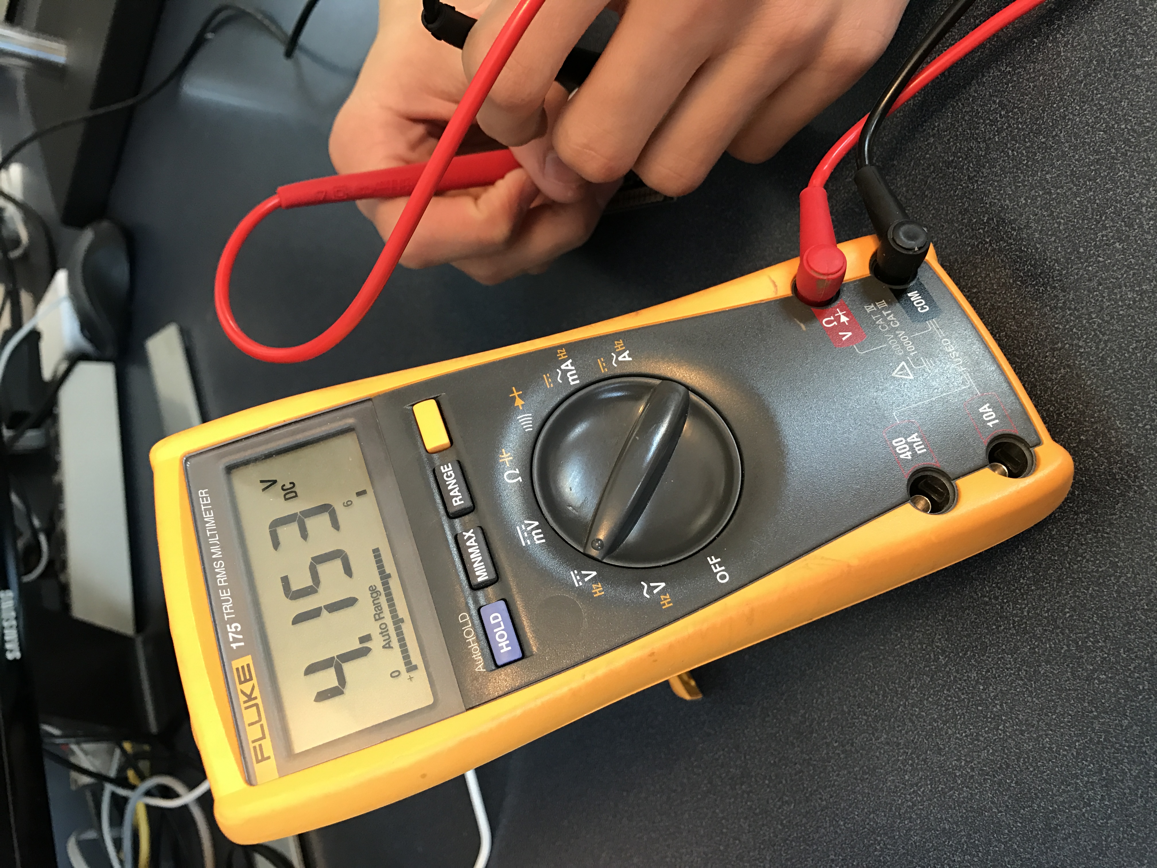
Not perfect and I wondered why I got 4.1v instead of 3.3v. But, the system will work at 4.1v so I deferred solving the problem until later. [Edit: It turns out that I did something really stupid and then got lucky. I will post soon about exactly what happened and how I fixed it.]
Test the OLED LCD Screen
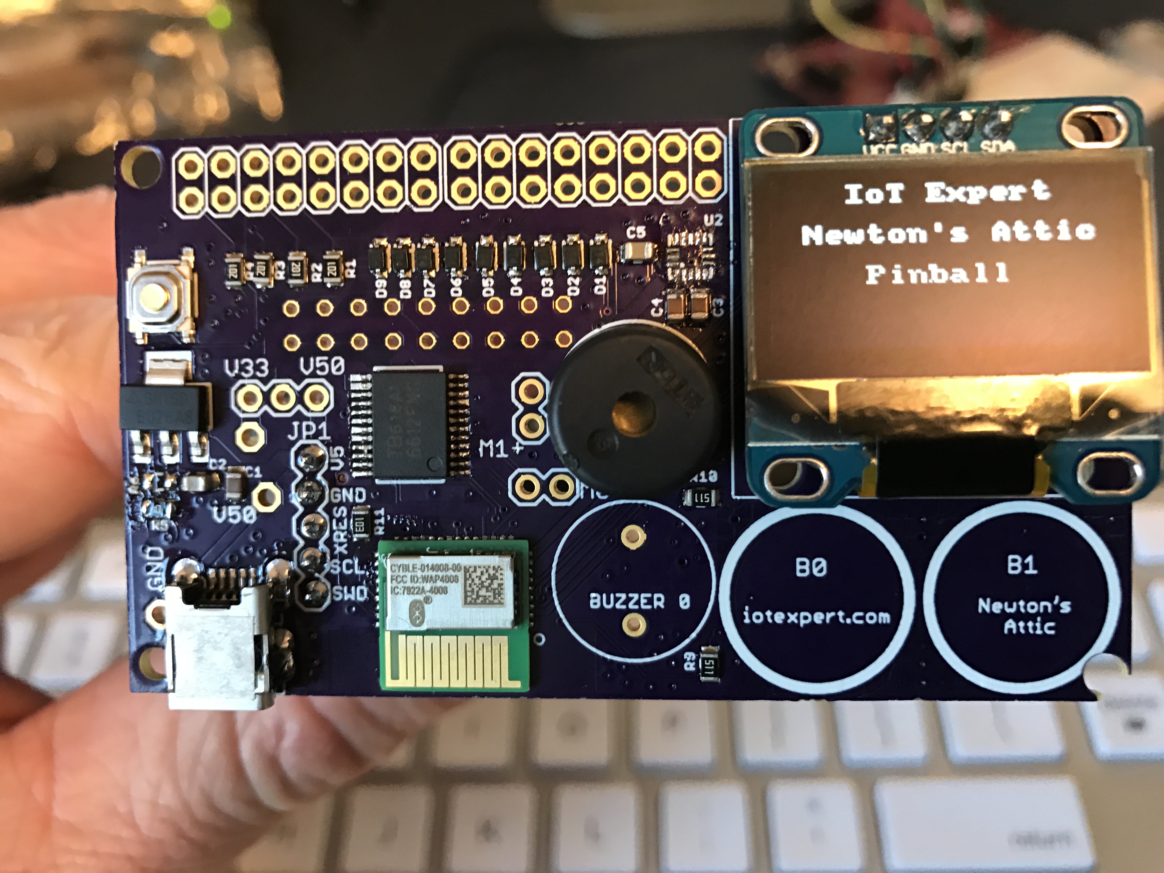
Before I soldered in the LCD display, I decided to measure the I2C pins to make sure they were what I was expecting. Unfortunately, when I measured them, I had about 800 ohms of resistance between the VCC and Ground which didn’t make a bit of sense. To make matters worse the SDA and SCL were essentially shorted to ground. After thinking about it for a while, I decided that the most likely culprit was the QFN accelerometer (which is also attached to the I2C bus). That tiny little chip, with no-visible leads and 0.5mm pitch pads is an absolute beast to solder (more on this problem in a future post). The accelerometer looked “OK”, but I decided to remove it anyway using my hot air tool. As soon as I got it off the board I could see a big blob of solder on the pads. After I cleaned up the blob of solder with a copper braid and soldering iron, I retested all of the pins. They were now fine. So I went ahead and soldered the display into the board (which also turned out to be a bad idea). You can see the (unpopulated) accelerometer footprint just to the left of the display.
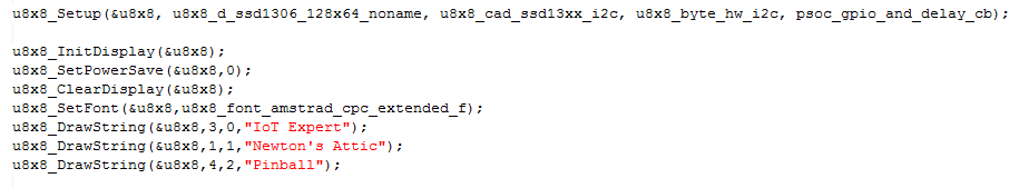
To test the display I ported Oliver Kraus’ U8G2 library to the PSoC. This library lets you use an I2C to interface with a bunch of different small OLEDs. You can read more about using the display in a future post. Here is the block of code that makes the display work:
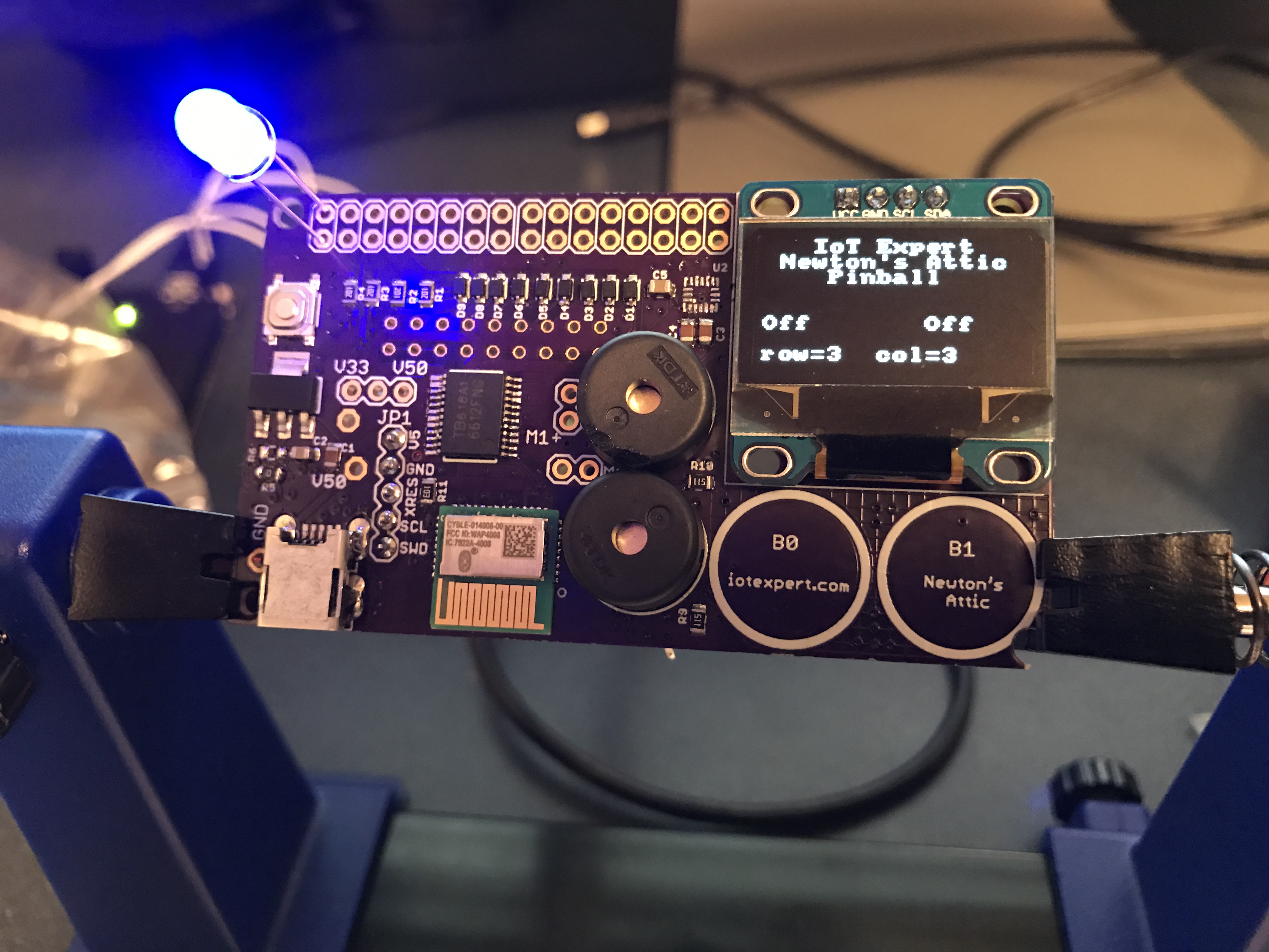
Test the CapSense
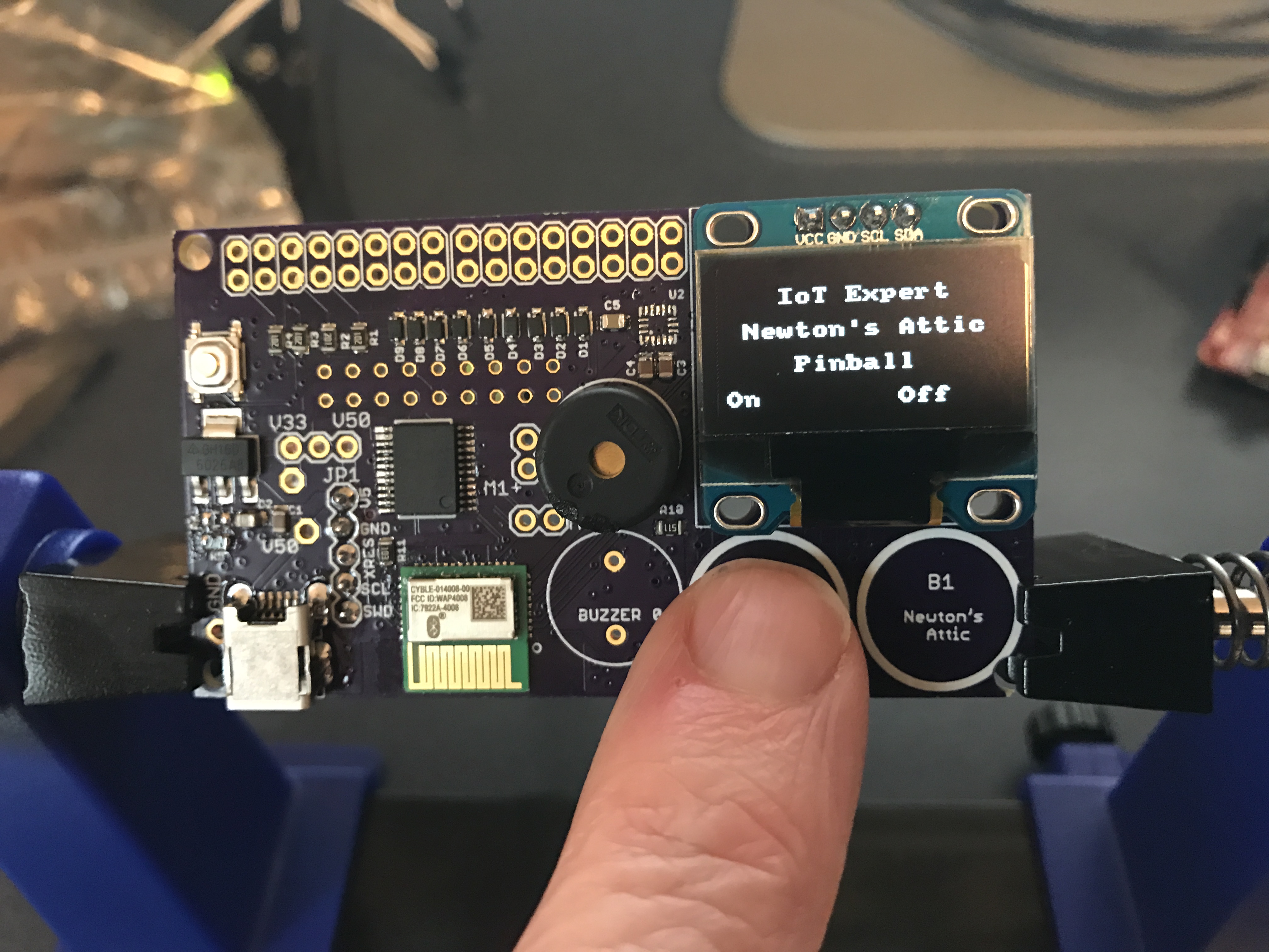
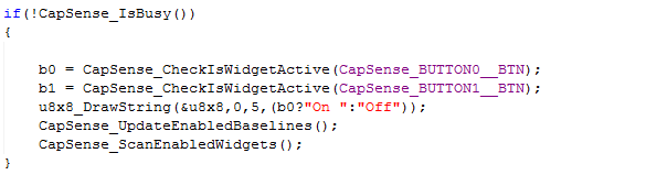
In order to test the CapSense buttons I wrote a simple block of firmware to read the state of the buttons and display that state on the screen:
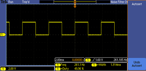
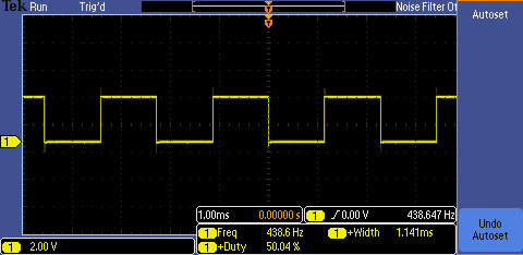
Test the Buzzers
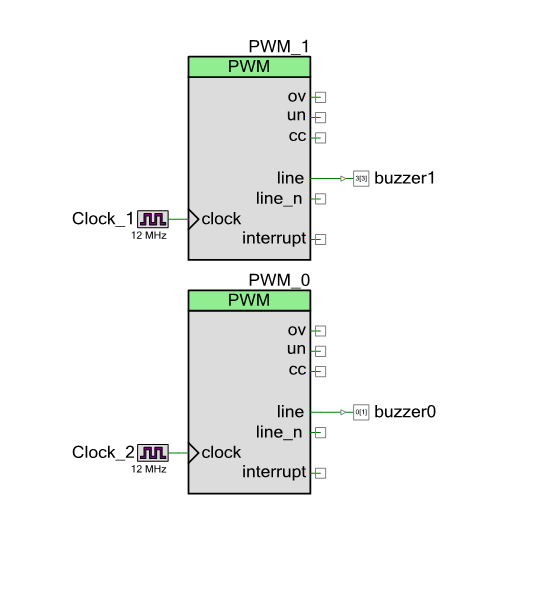
In order to test the buzzers, I just connected them to the PWMs and drove a square wave of 262Hz and 440Hz.
Here is the schematic for that circuit:
Test the Motor Driver
In order to test the motor drivers, I used a PWM to drive a 50Hz Square wave onto the output. Unfortunately, I got this:
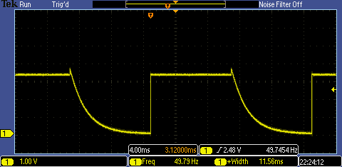
Something is wrong. When I first saw this waveform I wasn’t too happy. But after doing some digging I figured out how to fix it. This will be the subject of an upcoming post. The good thing about this waveform is that my daughter, Anna, is studying exponentials functions in Calculus right now. She recently asked me if there was an useful application of f(x) = e^x. This was a perfect way to show her a practical application of a differential equation.
Test the LEDs
To test the LEDs I used the switching LED matrix component program that I showed in an earlier post. To make things easier, I just stuck an LED in each pair of holes to make sure that they were working. Here is a picture:
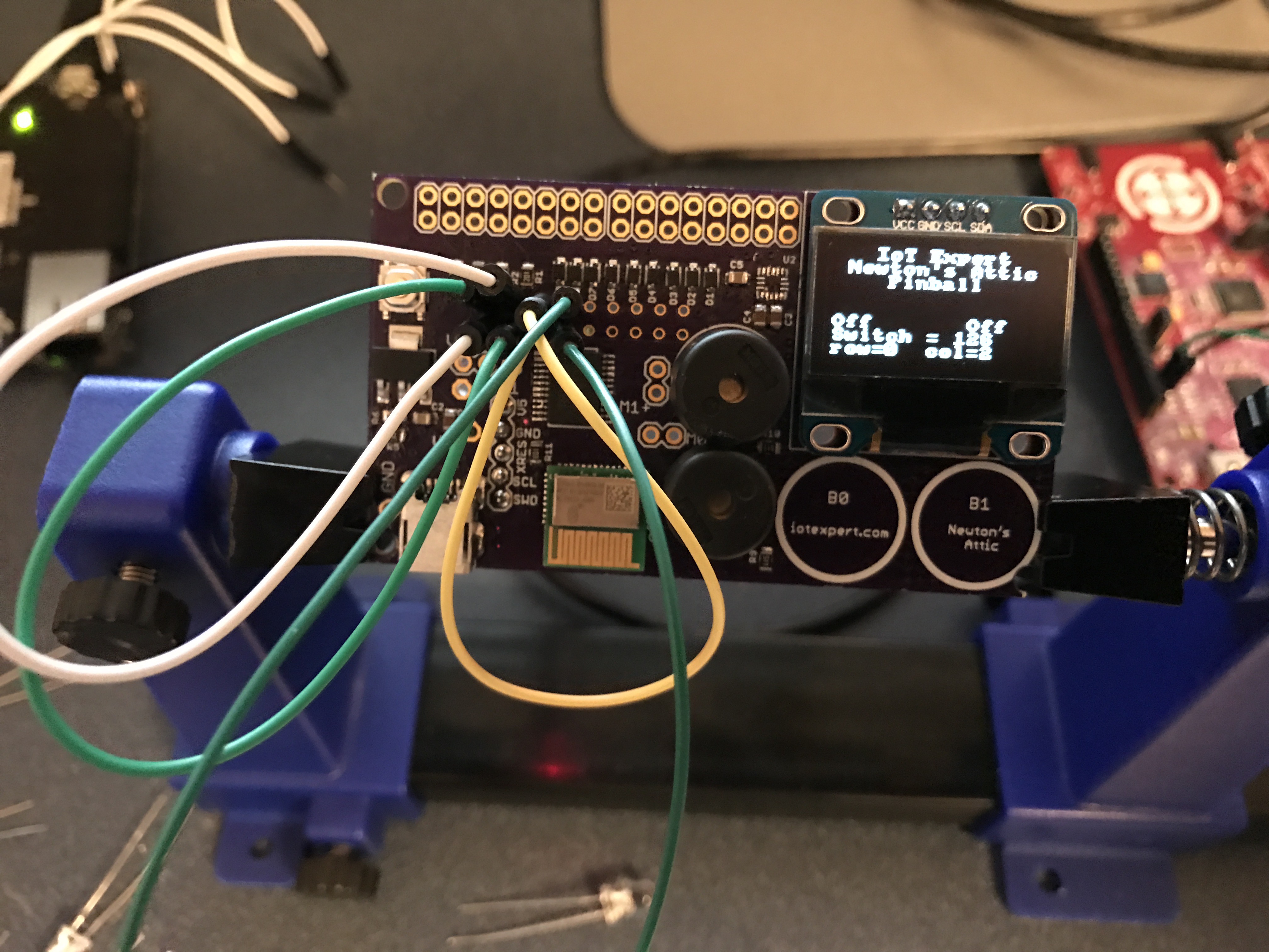
Test the Switches
To test the switches, I used the Switch Matrix Component that I talked about in detail in a previous post. In order to see the switches in their on state, I just plugged in a wire. Here is a picture of a few of them being tested.
Test the Accelerometer
As I mentioned earlier in this post, the accelerometer had a big nasty blob of solder under it which shorted SDA/SCL to ground. I am going to dedicate an entire post to fixing this problem.
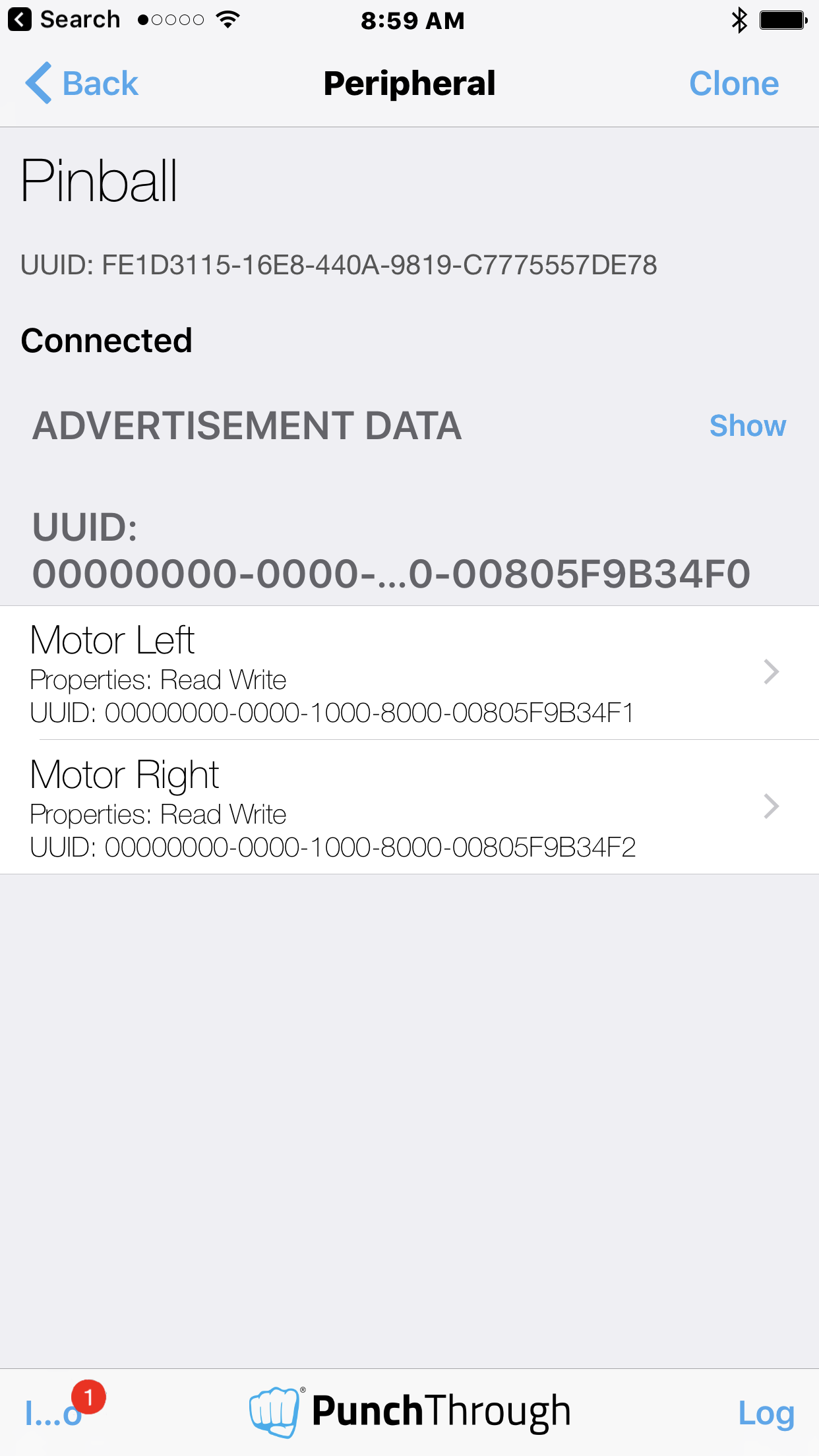
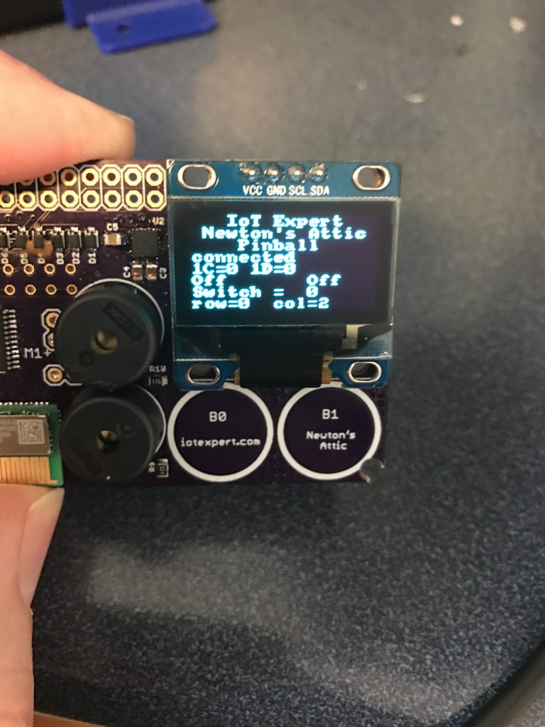
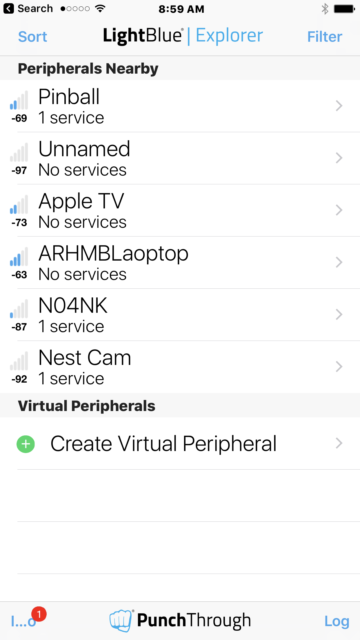
Test the Bluetooth
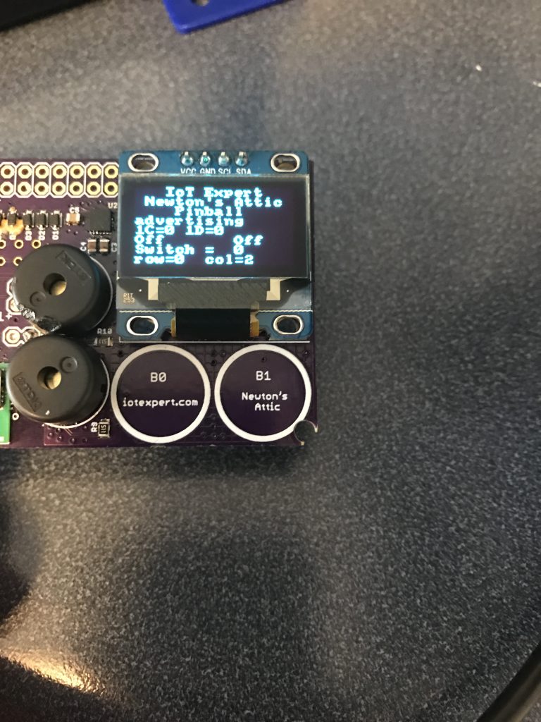
The very last sub-system to test is the Bluetooth. I decided to put in enough firmware that the device could:
- Advertise
- Disconnect
- Restart advertising
And display all of that on the OLED. Here is a picture:
You can find all of the source code and files at the IOTEXPERT site on github.
Index
Description
Pinball: Newton's Attic Pinball
An introduction to the project and the goals
Pinball: Lotsa Blinking LEDs
Everyone needs a bunch of LEDs on their Pinball Machine
Pinball: Matrix LEDs (Part 1)
Saving PSoC pins by using a matrix scheme
Pinball: Matrix LEDs (Part 2)
Solving some problems with the matrix
Pinball: Matrix LEDs Component
How to turn the Matrix LED into a component
Pinball: A Switch Matrix
Implementing a bunch of switches
Pinball: Switch Matrix Component (Part 1)
The switch matrix component implementation
Pinball: Switch Matrix Component (Part 2)
The firmware for matrix component
Pinball: Switch Matrix Component (Part 3)
Test firmware for the matrix component
Pinball: The Music Player (Part 1)
The schematic and symbol for a Music Player component
Pinball: The Music Player (Part 2)
The Public API for the Music Player component
Pinball: The Music Player (Part 3)
The firmware to make the sweet sweet music
Pinball: The Music Player (Part 4)
The test program for the music player
Pinball: The Motors + HBridge
Using an Bridge to control DC Motors
Pinball: The Eagle Schematic
All of the circuits into an Eagle schematic
Pinball: The Printed Circuit Board 1.0
The first Eagle PCB layout of the printed circuit board
Pinball: The PCB Version 1.0 Fail
Problems with the first version of the Eagle PCB layout
Pinball: PCB Layout 1.2 Updates using Eagle
Fixing the errors on the first two versions of the Eagle PCB
Pinball: Assemble and Reflow the 1.2 PCB
Assembling the Eagle PCB
Pinball: Testing the Eagle PCB
Firmware to test the newly built Pinball printed circuit board
Pinball: Debugging the Motor Driver
Fixing the motor driver PSoC project
Pinball: Hot-Air Reworking the Accelerometer Solder
Using a Hot-Air Rework tool to reflow a QFN
Pinball: Debugging the LM317 Power Supply- A Tale of Getting Lucky
Debugging the LM317/LM117 power supply
No comment yet, add your voice below!