In the post entitled “Pinball: Matrix LEDs Component” I took you through the steps to create an LED Component. In this post I will take you through the steps to do the same thing, create a component, for the Switch Matrix that I talked about in the last post. Since I did the LED component I figured out how to embed the pins into the component and have a variable number. I am going to go back and fix the LED component.
The first step to create the Switch Matrix Component is to click on the “Component” tab so that you can create a new component in the “Pinball Components” library.
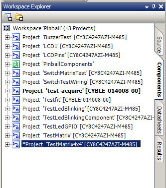
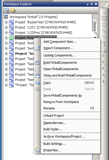
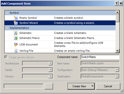
Now, add a new component to the library by right clicking the “Pinball Components” library and selecting “Add Component Item…”
Start by creating a Symbol for the “SwitchMatrix” component. If you don’t want to draw all of the parts of the symbol then just use the automatic “Symbol Wizard”.
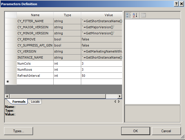
Next, add three component parameters, which will be editable by the user of the component. Do this by right clicking on the blank canvas part of the symbol editor and select “Symbol Parameters…”. Add NumCols, NumRows, and RefreshInterval. These will be usable in your source code as $NumCols, $NumRows and $RefreshInterval.
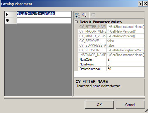
Then, put the component into the right place in the component catalog by right clicking on the blank canvas in the symbol editor and selecting “Properties”
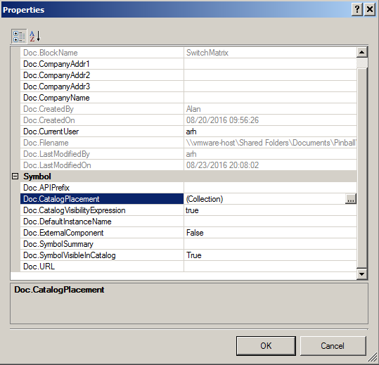
Select the “Doc.CatalogPlacement” and type in the place where you want the component to show up in the Component browser. In this case we want it in the “Pinball” tab, in the “Switch” category. The name of the component will be “SwitchMatrix”
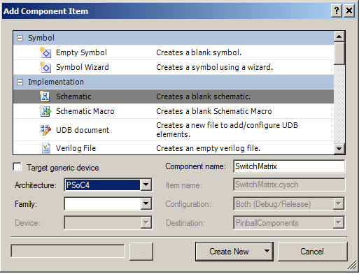
For this component I want the user to be able to change the number of rows and columns. I will do this by embedding the row and col digital input/output pins inside of the component. And, the row,col pin components will be busses so that I can change the number. First, you need to add a schematic to your component to hold the pins.
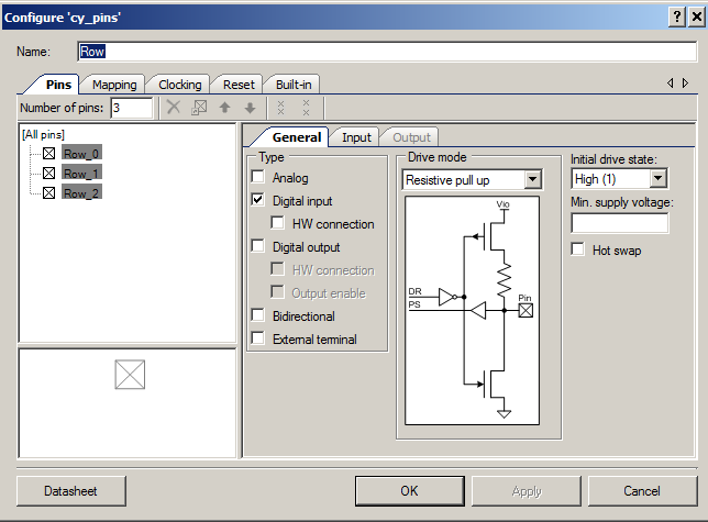
I need to place a digital input pin (for the rows). I select the number of pins to be 3 (this parameter will be changed by our customizer). Also turn on the pull up resistors.
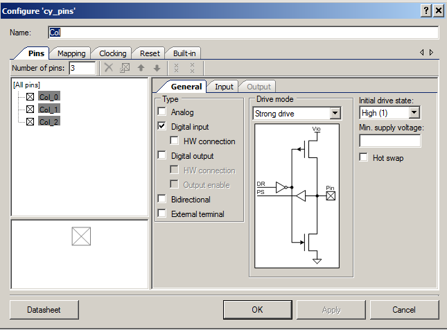
Then I place a digital output pin for the columns.
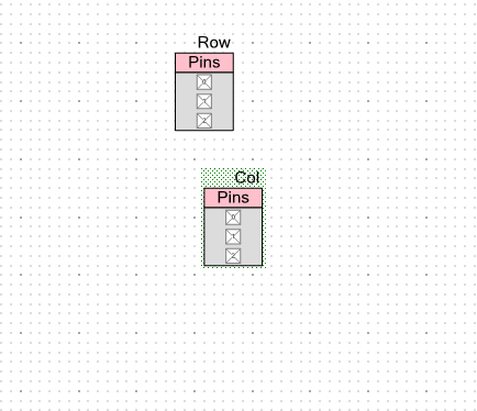
When I am done I will have a schematic that looks like this:
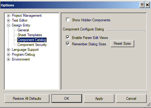
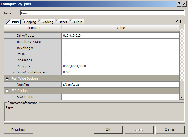
Now I need to fix things up so that the user of the component can edit the number of pins. To do this, I need to be able to edit the hidden parameter on the Cypress pins component which has the property of the number of pins in the bus. To do this I first need to enable the secret menu which lets me edit the raw parameter. This is on the Tools->options->design entry->component catalog menu. You can see the “Enable Param Edit Views”. By selecting this option you will be able to edit the raw parameter values on the components.
Once you have enabled the menu you will be able to right click on the “Pins” tab of the component and show the “Show Expression View”
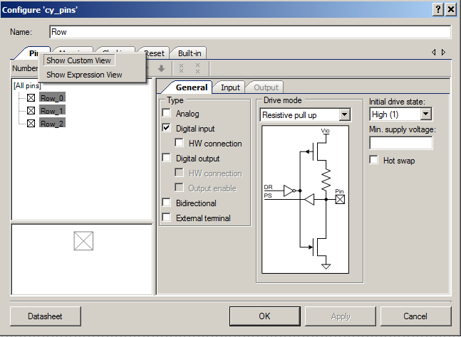
Instead of the graphical interface to the component (shown above) you will have a list of the raw parameters (shown below) Scroll down to “NumPins” and change it to the parameter that I put onto the symbol, “$NumRows”
Lastly, do exactly the same thing for another pin for the Columns. In the next post I will show and explain the source code for the component.
You can find all of the source code and files at the IOTEXPERT site on github.
Index
Description
Pinball: Newton's Attic Pinball
An introduction to the project and the goals
Pinball: Lotsa Blinking LEDs
Everyone needs a bunch of LEDs on their Pinball Machine
Pinball: Matrix LEDs (Part 1)
Saving PSoC pins by using a matrix scheme
Pinball: Matrix LEDs (Part 2)
Solving some problems with the matrix
Pinball: Matrix LEDs Component
How to turn the Matrix LED into a component
Pinball: A Switch Matrix
Implementing a bunch of switches
Pinball: Switch Matrix Component (Part 1)
The switch matrix component implementation
Pinball: Switch Matrix Component (Part 2)
The firmware for matrix component
Pinball: Switch Matrix Component (Part 3)
Test firmware for the matrix component
Pinball: The Music Player (Part 1)
The schematic and symbol for a Music Player component
Pinball: The Music Player (Part 2)
The Public API for the Music Player component
Pinball: The Music Player (Part 3)
The firmware to make the sweet sweet music
Pinball: The Music Player (Part 4)
The test program for the music player
Pinball: The Motors + HBridge
Using an Bridge to control DC Motors
Pinball: The Eagle Schematic
All of the circuits into an Eagle schematic
Pinball: The Printed Circuit Board 1.0
The first Eagle PCB layout of the printed circuit board
Pinball: The PCB Version 1.0 Fail
Problems with the first version of the Eagle PCB layout
Pinball: PCB Layout 1.2 Updates using Eagle
Fixing the errors on the first two versions of the Eagle PCB
Pinball: Assemble and Reflow the 1.2 PCB
Assembling the Eagle PCB
Pinball: Testing the Eagle PCB
Firmware to test the newly built Pinball printed circuit board
Pinball: Debugging the Motor Driver
Fixing the motor driver PSoC project
Pinball: Hot-Air Reworking the Accelerometer Solder
Using a Hot-Air Rework tool to reflow a QFN
Pinball: Debugging the LM317 Power Supply- A Tale of Getting Lucky
Debugging the LM317/LM117 power supply

No comment yet, add your voice below!