WICED Bluetooth Using the CYW20719
#
Title
Comment
0
A Two Hour WICED Bluetooth Class
WICED Bluetooth Using the CYW20719 in all its glory
1
Resources
Links to all of the Cypress WICED information including videos, application notes etc.
2
Your First Project
Making Hello World & the Blinky LED
3
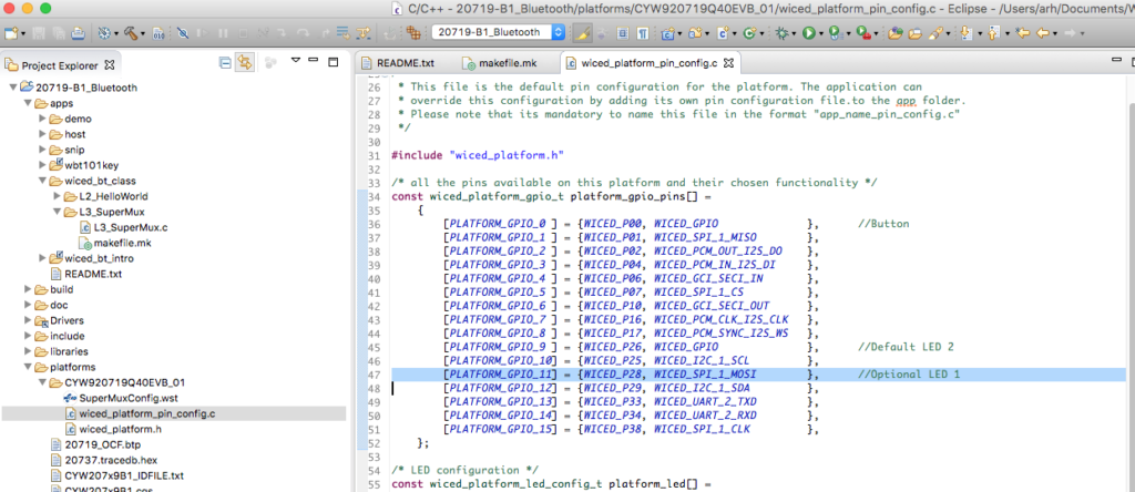
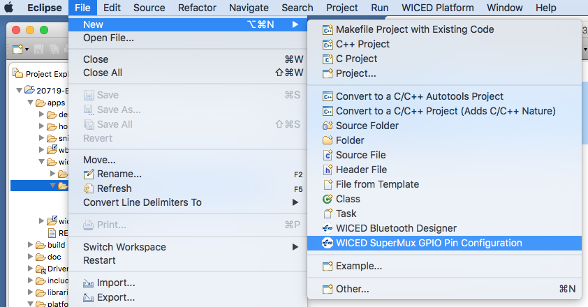
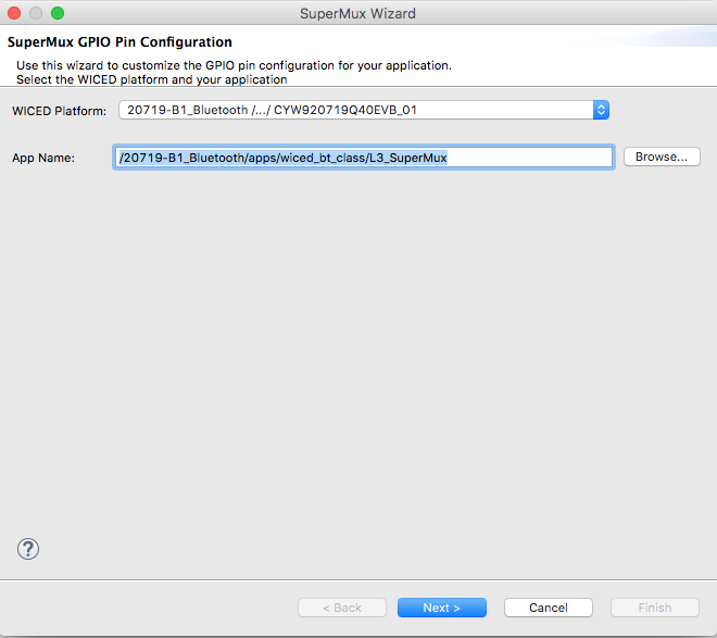
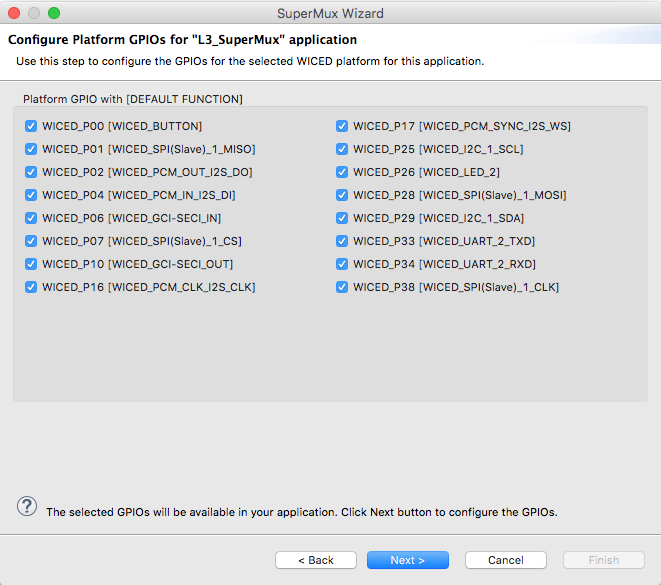
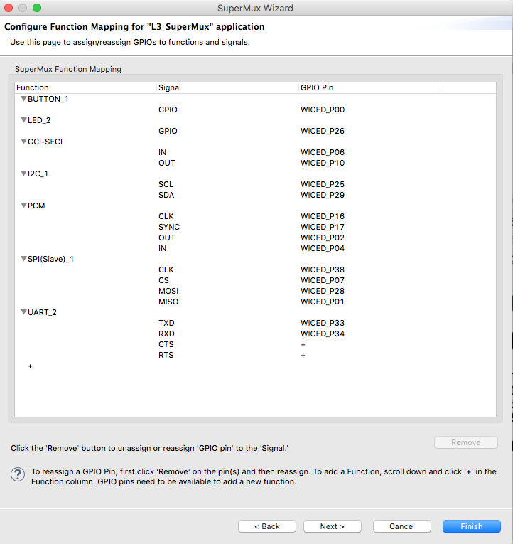
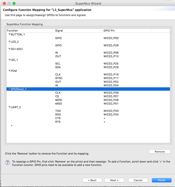
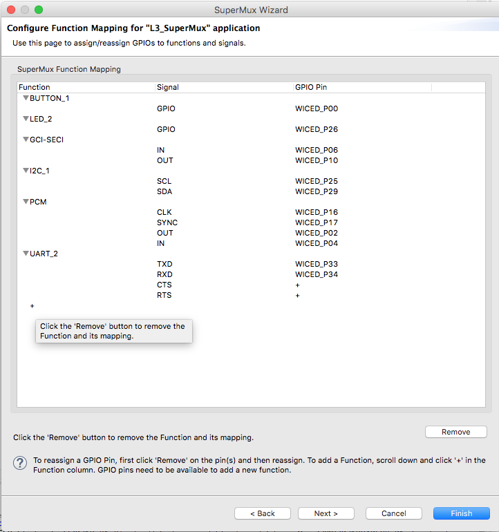
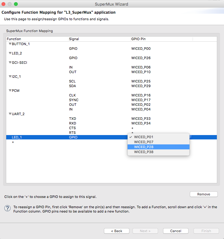
The Super Mux Tool
Learning about platforms and the Super Mux Tool
4
Snips
Using the example projects to learn Bluetooth
5
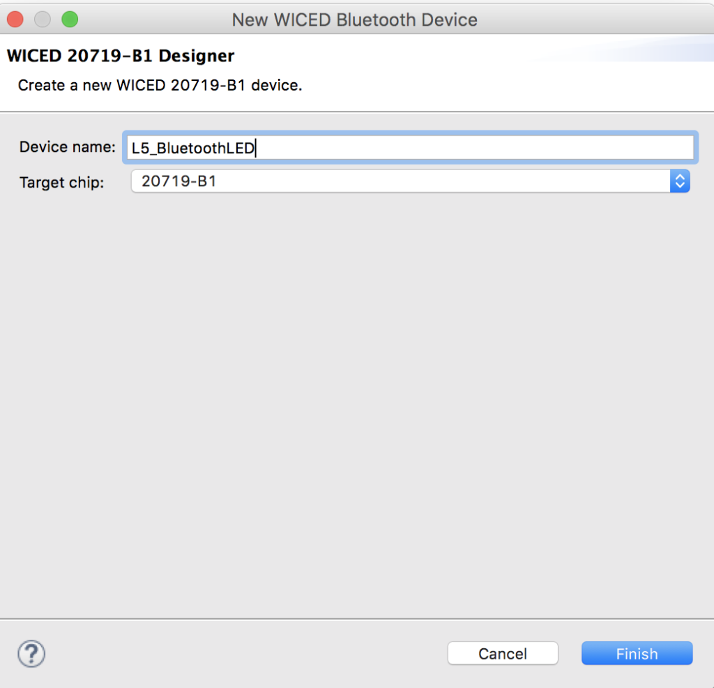
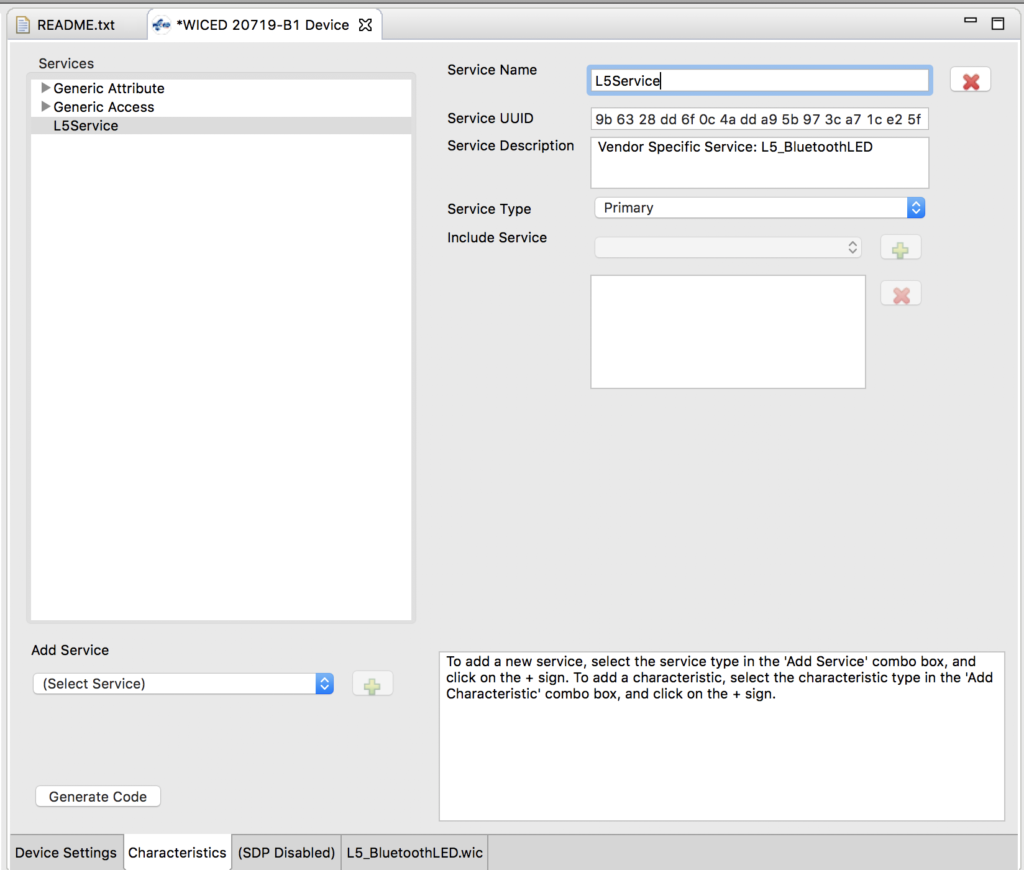
Bluetooth Designer
Using the tool to customize a project and get going fast
6
The CCCD & Notification
Writing back to the Central
7
Advertising Beacon
Building a beacon project to advertise your custom information
8
Scanner
Viewing the world around you
9
Bluetooth Classic SPP
Using the Serial Port Profile to Transmit Lots of Data
Source code:
- git@github.com:iotexpert/wiced_bt_intro.git
- https://github.com/iotexpert/wiced_bt_intro
Summary
In the last lesson we built our first Bluetooth design using BT Designer. In that lesson I showed you how to
- Build a project using BT Designer
- Start Advertising
- Get connected Central –> Peripheral
- Read & Write the data from the Central to the Peripheral
In this lesson we are going to answer the question how does the Peripheral write data back to the Central by adding a button to our last project. When the button is pressed it will send the state of the button (0 or 1) back to Central.
The important concepts in this lesson are
- BLE Notifications
- BLE Client Configuration Characteristic Descriptor
- How to manually modify the Gatt DB
I will follow these steps:
- Copy the project L5_BluetoothLED into L6_BluetoothLEDButton
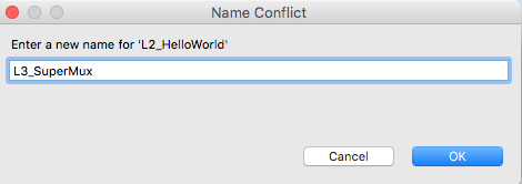
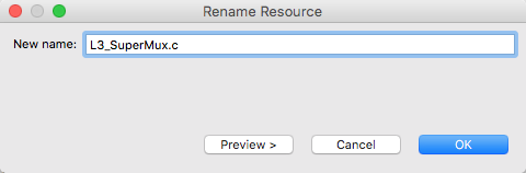
- Rename all of the files to be L6_BluetoothLEDButton….
- Fix the makefile
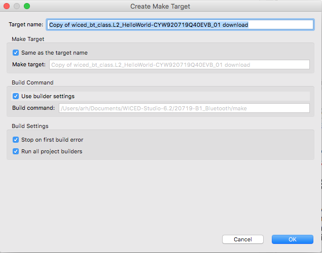
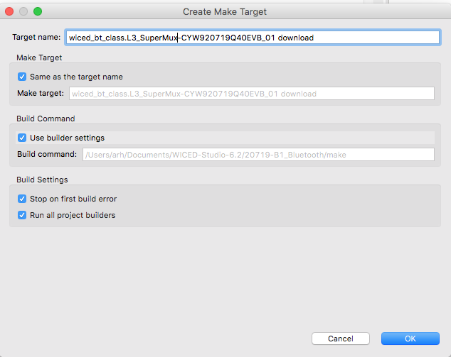
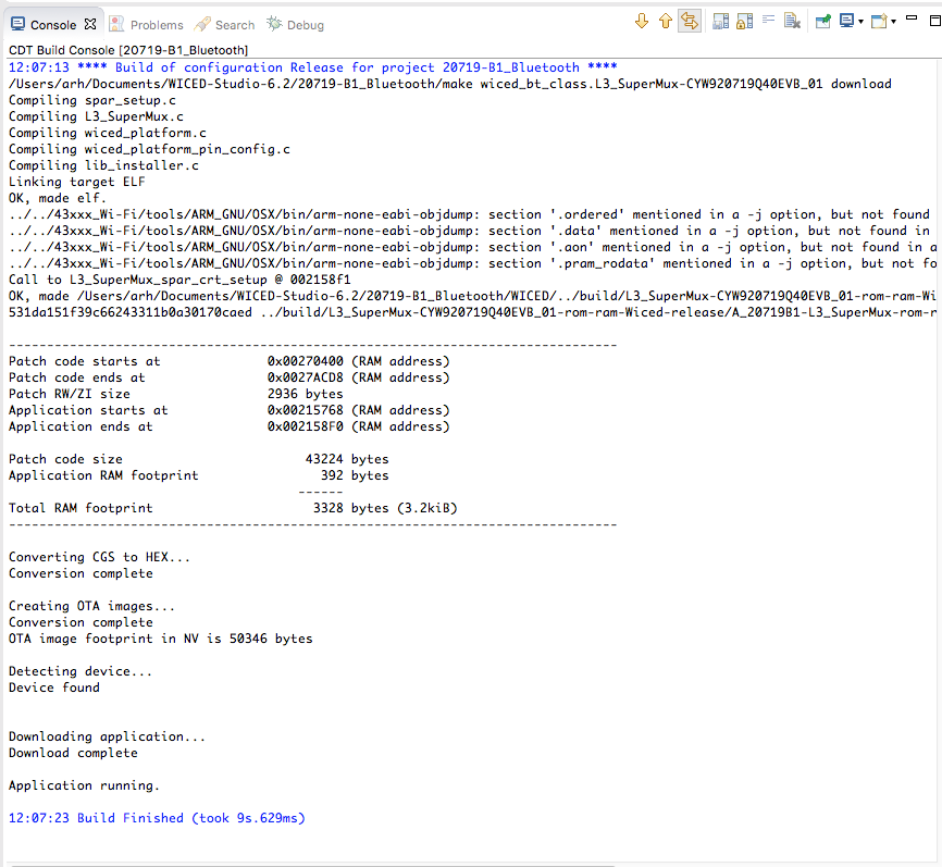
- Create a make target and make sure that it still works
- Modify L6_BluetoothLEDButton_db.h to add UUID and Handles for the new Button characteristic
- Modify L6_BluetoothLEDButton_db.c to add the Button characteristic to the GATT Database
- Add initial value arrays for the Button characteristic, CCCD and User Description
- Add the Button values to the GATT lookup table
- Add connection id uint16_t connection_id
- Modify the connection handler l5_bluetoothled_connect_callback
- Create a button callback function
- Register the button callback
BLE Concepts
A Bluetooth Peripheral is allowed to send Notifications to a Central that a value in the GATT Database has changed. However, it is only allowed to do this when the Client Characteristic Configuration Descriptor (CCCD) is set. In other words a Central can register with a Peripheral that it is interested in seeing changes of Characteristics by writing a 0x01 into the CCCD. The CCCD is just another value in the attribute database.
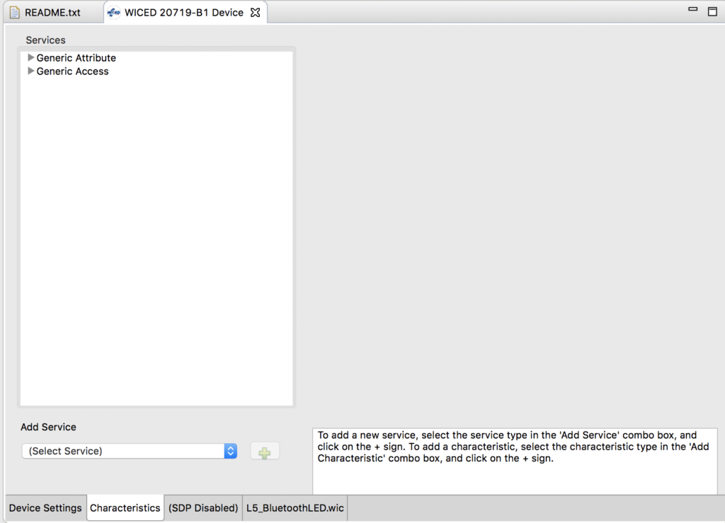
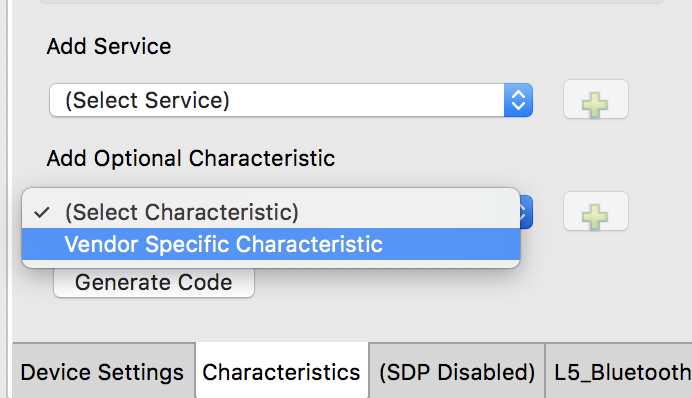
To setup a Characteristic for Notifications you need to modify the GATT Database by
- Adding the notification property to the Characteristic in the GATT Database
- Adding the CCCD to the GATT database
In the your program, when a value is changed, you should check to see if the CCCD is set, then send a notification if it is set.
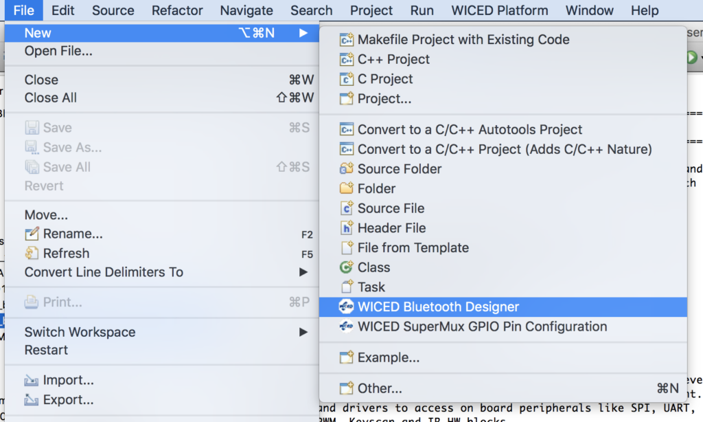
Implement the Project
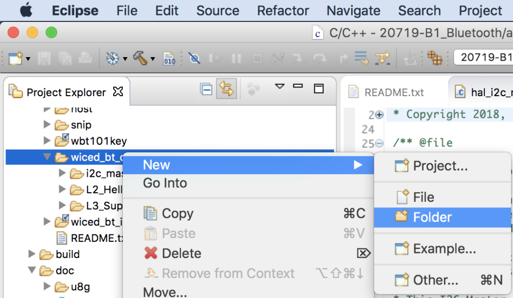
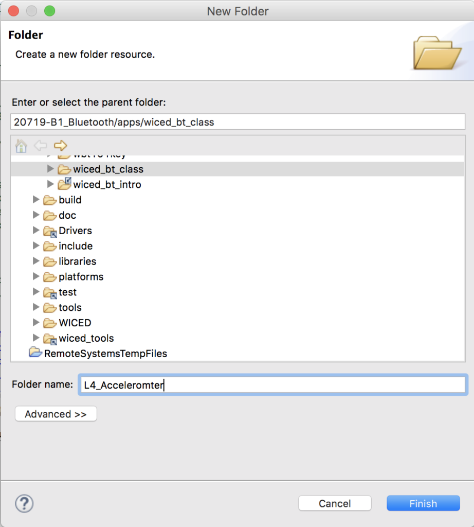
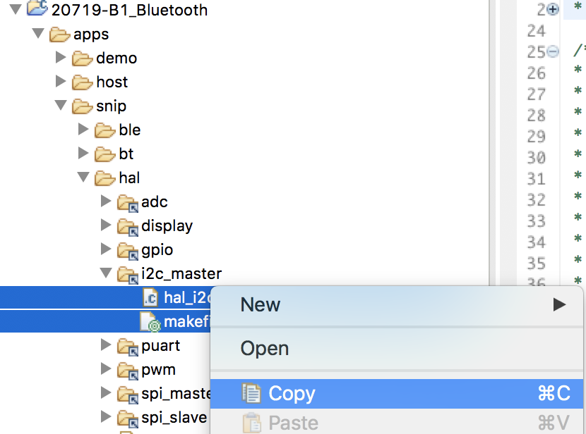
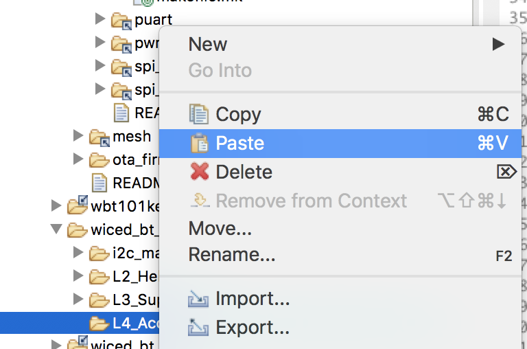
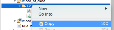
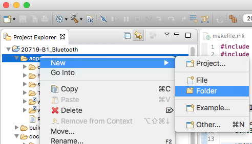
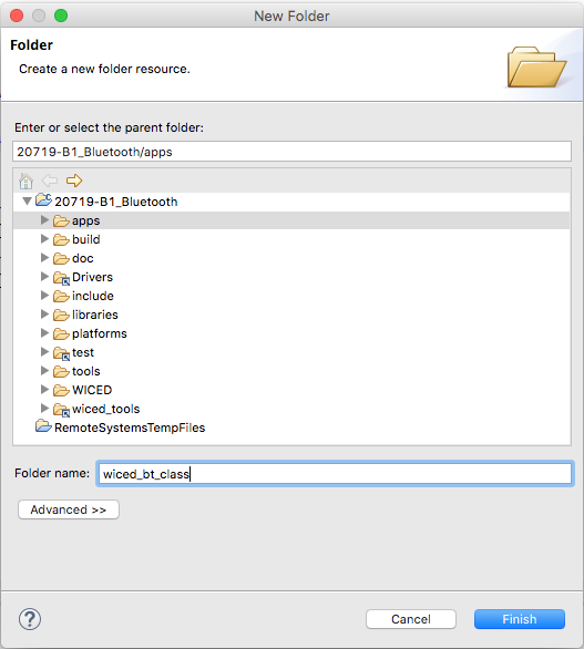
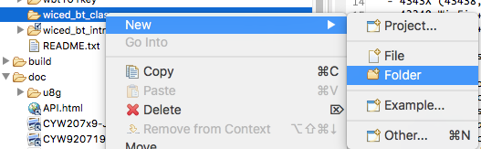
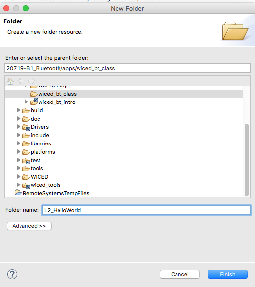
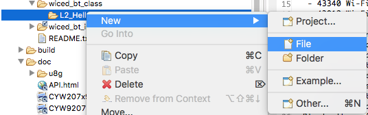
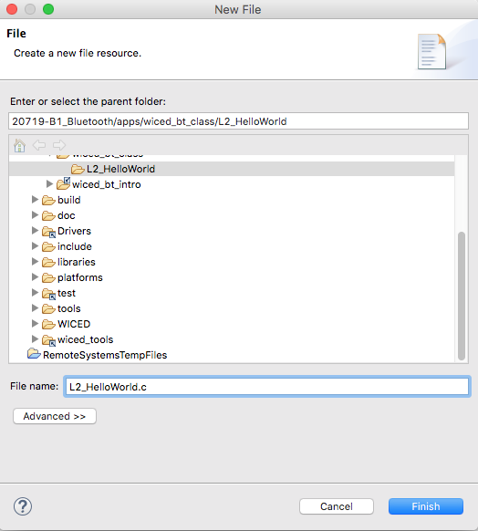
I am going to build this project on top of the code from L5_BluetoothLED. So, start this project by copying the project L5_BluetoothLED into L6_BluetoothLEDButton by doing copy/paste
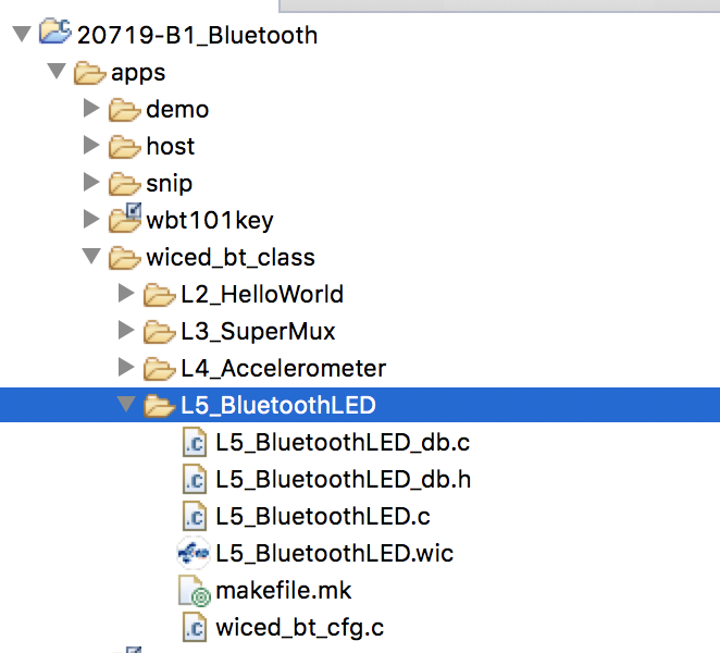
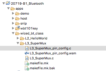
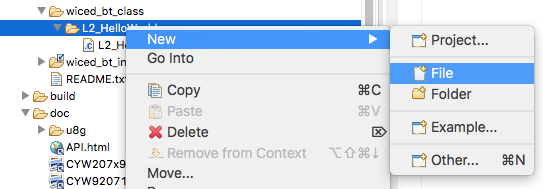
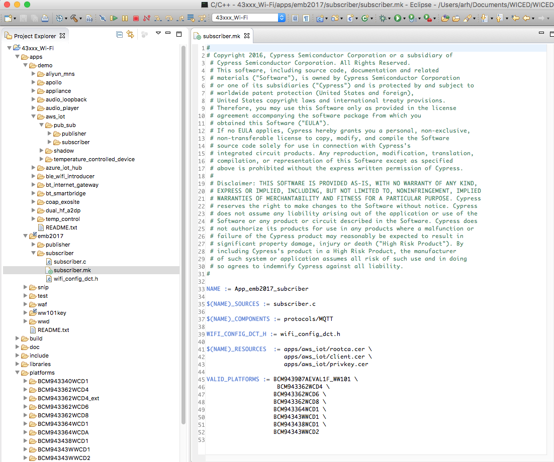
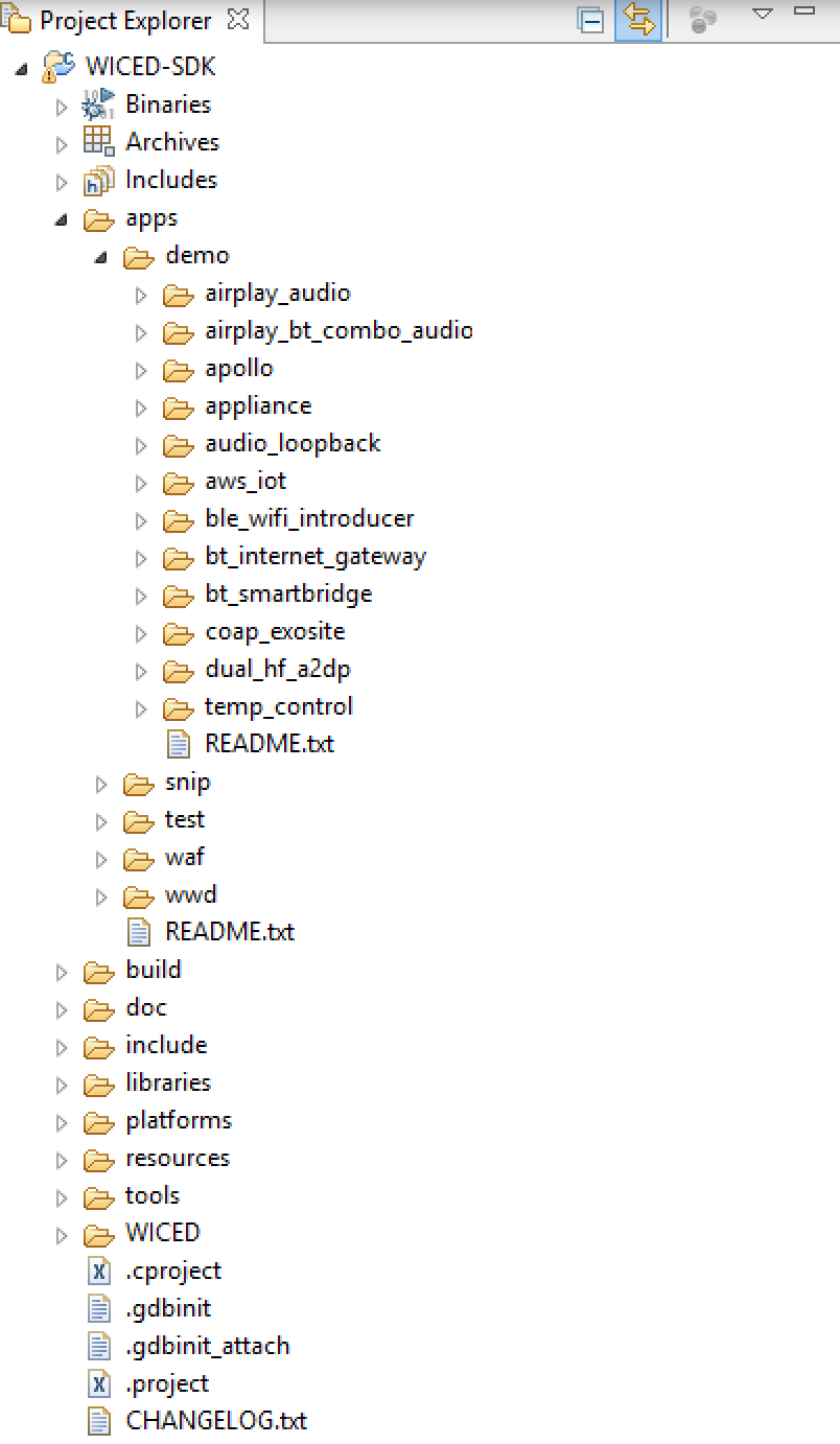
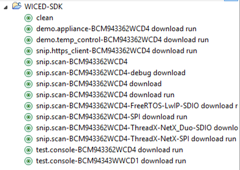
Rename all of the files to be L6_BluetoothLEDButton…. your project should look like this.
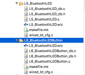
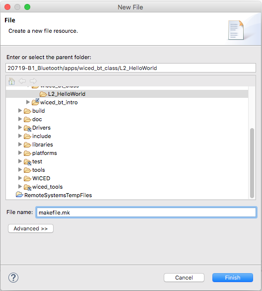
Fix the makefile.mk (because the file names have changed)
#
# This file has been automatically generated by the WICED 20719-B1 Designer.
#

APP_SRC = L6_BluetoothLEDButton.c
APP_SRC += L6_BluetoothLEDButton_db.c
APP_SRC += wiced_bt_cfg.c

C_FLAGS += -DWICED_BT_TRACE_ENABLE

# If defined, HCI traces are sent over transport/WICED HCI interface
C_FLAGS += -DHCI_TRACE_OVER_TRANSPORT
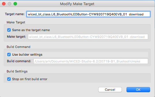
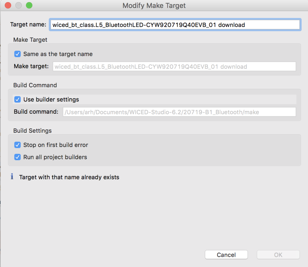
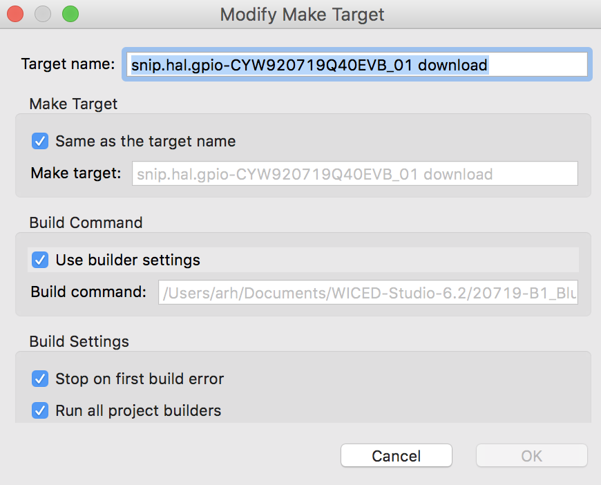
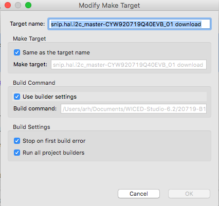
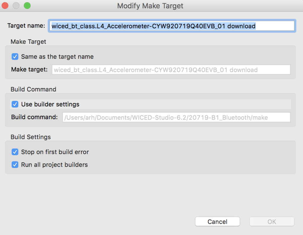
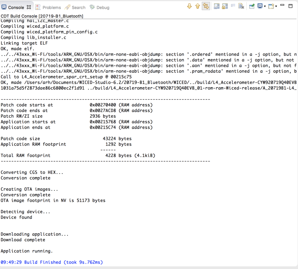
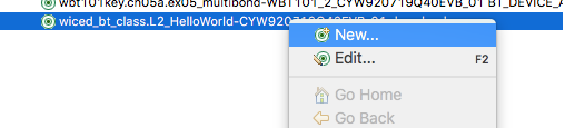
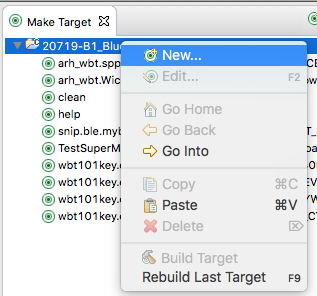
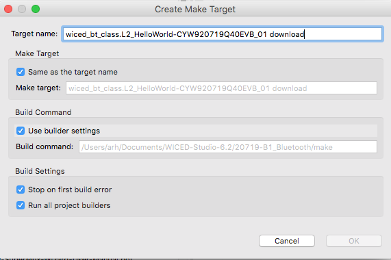
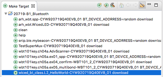
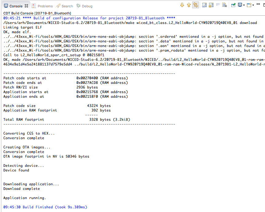
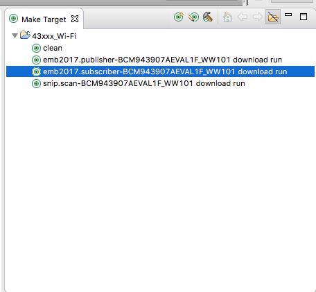
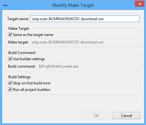
Create a make target and make sure that it still works
Modify L6_BluetoothLEDButton_db.h to create a UUID for the new Button characteristic
#define __UUID_L5SERVICE_BUTTON 0x2A, 0xbf, 0x86, 0xa6, 0xc8, 0x6c, 0x4e, 0xa5, 0xaa, 0x56, 0xbd, 0xac, 0x72, 0x80, 0x93, 0xa9
Modify L6_BluetoothLEDButton_db.h to add Handles for the new Button characteristic
#define HDLC_L5SERVICE_BUTTON                      0x0030
#define HDLC_L5SERVICE_BUTTON_VALUE                0x0031
#define HDLD_L5SERVICE_BUTTON_USER_DESCRIPTION     0x0032
#define HDLD_L5SERVICE_BUTTON_CLIENT_CONFIGURATION 0x0033
Modify L6_BluetoothLEDButton_db.c to add the Button characteristic to the GATT Database
/* Characteristic 'BUTTON' */
CHARACTERISTIC_UUID128(HDLC_L5SERVICE_BUTTON, HDLC_L5SERVICE_BUTTON_VALUE,
__UUID_L5SERVICE_BUTTON, LEGATTDB_CHAR_PROP_READ | LEGATTDB_CHAR_PROP_NOTIFY,
LEGATTDB_PERM_READABLE ),
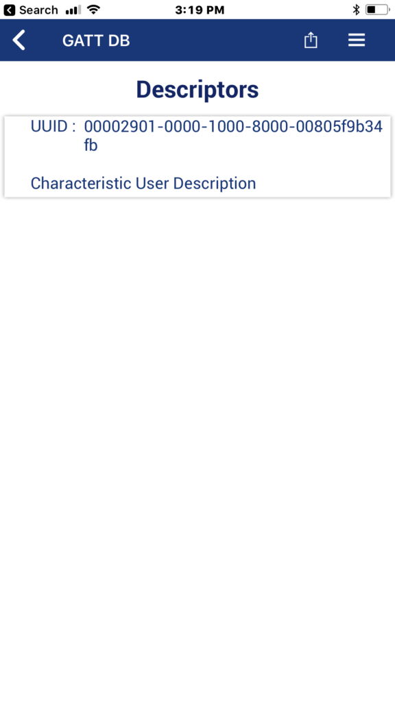
/* Descriptor 'Characteristic User Description' */
CHAR_DESCRIPTOR_UUID16 (HDLD_L5SERVICE_BUTTON_USER_DESCRIPTION,
UUID_DESCRIPTOR_CHARACTERISTIC_USER_DESCRIPTION, LEGATTDB_PERM_READABLE),
/* Descriptor CCCD */
CHAR_DESCRIPTOR_UUID16_WRITABLE(HDLD_L5SERVICE_BUTTON_CLIENT_CONFIGURATION,
UUID_DESCRIPTOR_CLIENT_CHARACTERISTIC_CONFIGURATION,
LEGATTDB_PERM_READABLE | LEGATTDB_PERM_WRITE_REQ ),
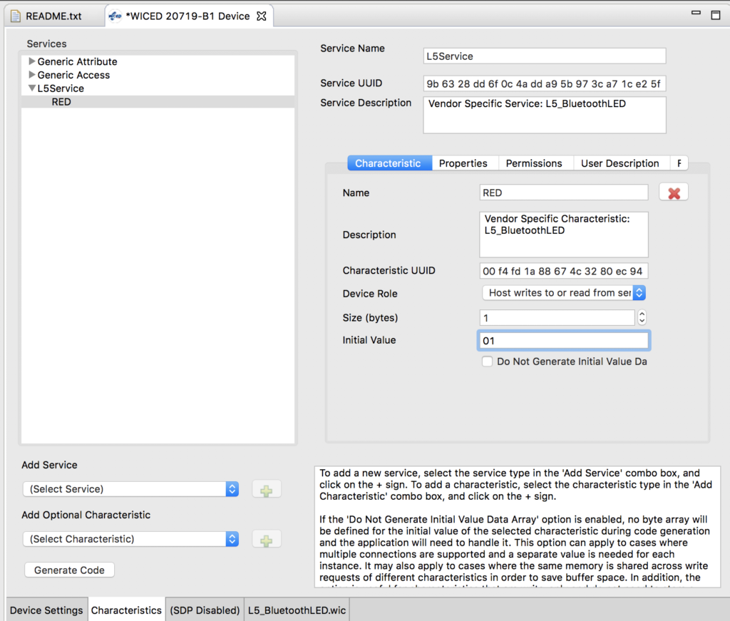
Add initial value arrays for the Button characteristic, CCCD and User Description into L6_ButtonLED.c
uint8_t l5_bluetoothled_l5service_button[] = {0x01};
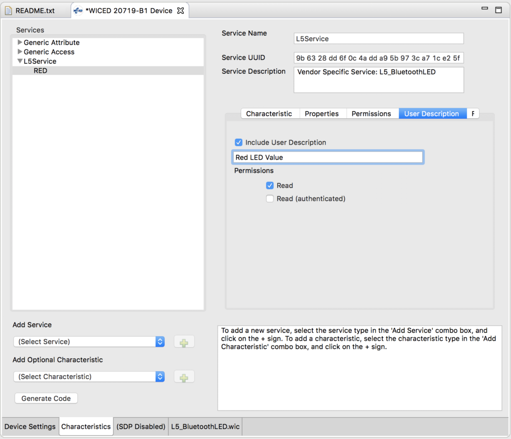
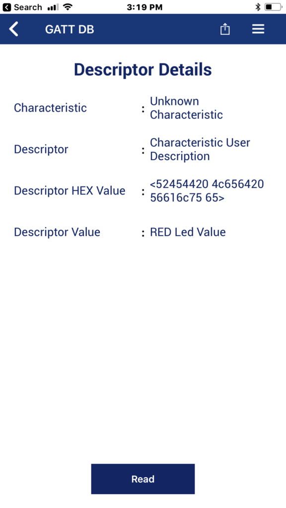
uint8_t l5_bluetoothled_l5service_button_user_description[] = "Button Value";
uint8_t l5_bluetoothled_l5service_button_cccd[] = {0x00,0x00};
Add the Button values to the GATT lookup table
    {HDLC_L5SERVICE_BUTTON_VALUE,              1,                                                      1,                                                      l5_bluetoothled_l5service_button},
    {HDLD_L5SERVICE_BUTTON_USER_DESCRIPTION,   sizeof(l5_bluetoothled_l5service_button_user_description)-1, sizeof(l5_bluetoothled_l5service_button_user_description)-1, l5_bluetoothled_l5service_button_user_description},
    {HDLD_L5SERVICE_BUTTON_CLIENT_CONFIGURATION, 2,      2,      l5_bluetoothled_l5service_button_cccd},
Add connection id uint16_t connection_id
uint16_t connection_id=0;
Modify the connection handler l5_bluetoothled_connect_callback. When you get a connection save it.
connection_id = p_conn_status->conn_id;
and when you get a disconnect put it back to 0
connection_id = 0;
Here is what the whole handler looks like now
/* GATT Connection Status Callback */
wiced_bt_gatt_status_t l5_bluetoothled_connect_callback( wiced_bt_gatt_connection_status_t *p_conn_status )
{
wiced_bt_gatt_status_t status = WICED_BT_GATT_ERROR;
if ( NULL != p_conn_status )
{
if ( p_conn_status->connected )
{
// Device has connected
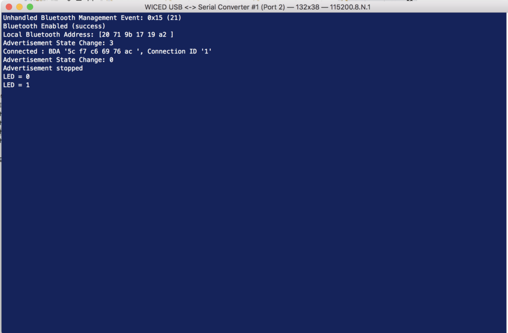
WICED_BT_TRACE("Connected : BDA '%B', Connection ID '%d'\n", p_conn_status->bd_addr, p_conn_status->conn_id );
/* TODO: Handle the connection */
connection_id = p_conn_status->conn_id;
}
else
{
// Device has disconnected
WICED_BT_TRACE("Disconnected : BDA '%B', Connection ID '%d', Reason '%d'\n", p_conn_status->bd_addr, p_conn_status->conn_id, p_conn_status->reason );
/* TODO: Handle the disconnection */
connection_id = 0;
/* restart the advertisements */
wiced_bt_start_advertisements(BTM_BLE_ADVERT_UNDIRECTED_HIGH, 0, NULL);
}
status = WICED_BT_GATT_SUCCESS;
}
return status;
}
Create a button callback function
void buttonISR(void *data, uint8_t port_pin )
{
l5_bluetoothled_l5service_button[0] = wiced_hal_gpio_get_pin_input_status(WICED_PLATFORM_BUTTON_1);
if(l5_bluetoothled_l5service_button_cccd[0] & GATT_CLIENT_CONFIG_NOTIFICATION)
{
wiced_bt_gatt_send_notification(connection_id, HDLC_L5SERVICE_BUTTON_VALUE, sizeof(l5_bluetoothled_l5service_button), l5_bluetoothled_l5service_button );
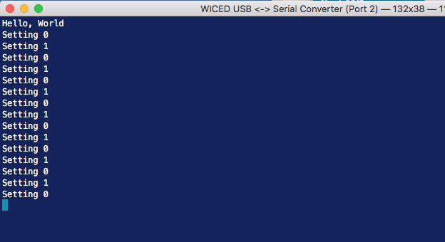
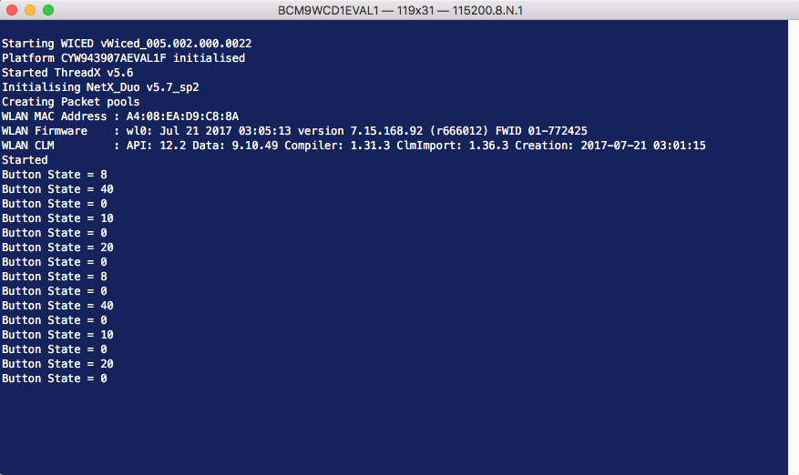
WICED_BT_TRACE( "Sent Button %d\n",l5_bluetoothled_l5service_button[0]);
}
}
In the function l5_bluetoothled_app_init you need to register the button callback to trigger when the button is pressed
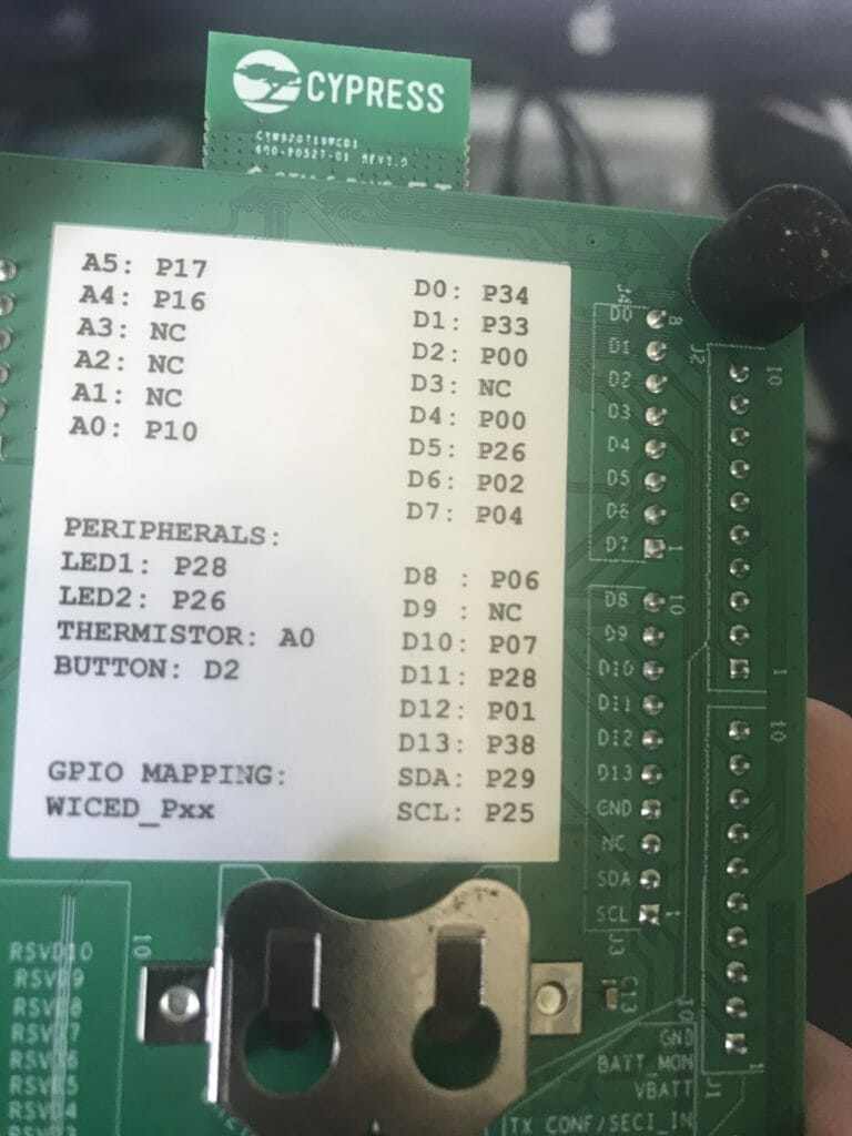
    wiced_hal_gpio_register_pin_for_interrupt( WICED_GPIO_PIN_BUTTON_1, buttonISR, NULL );
    wiced_hal_gpio_configure_pin( WICED_GPIO_PIN_BUTTON_1, ( GPIO_INPUT_ENABLE | GPIO_PULL_UP | GPIO_EN_INT_BOTH_EDGE ), GPIO_PIN_OUTPUT_HIGH );
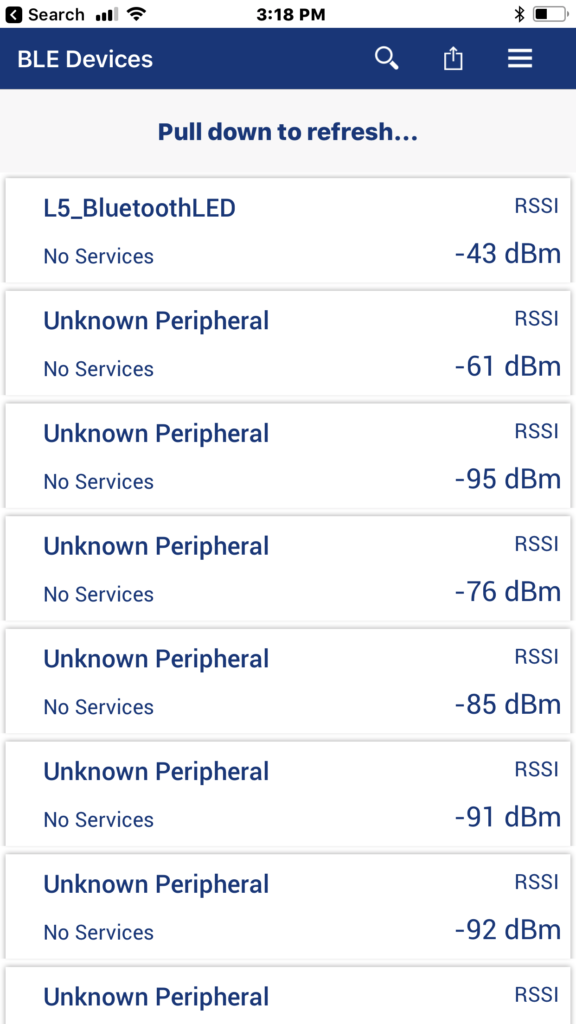
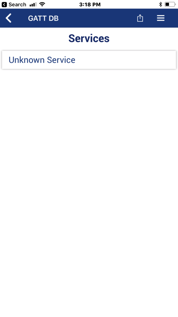
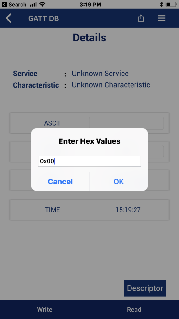
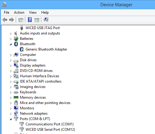
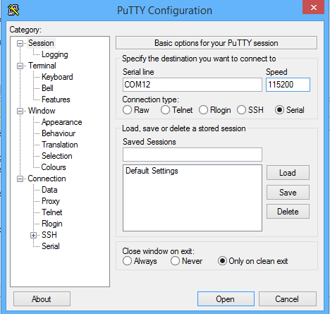
Test using CySmart
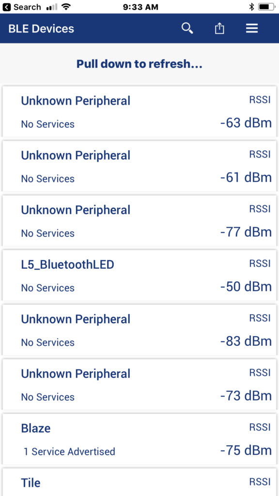

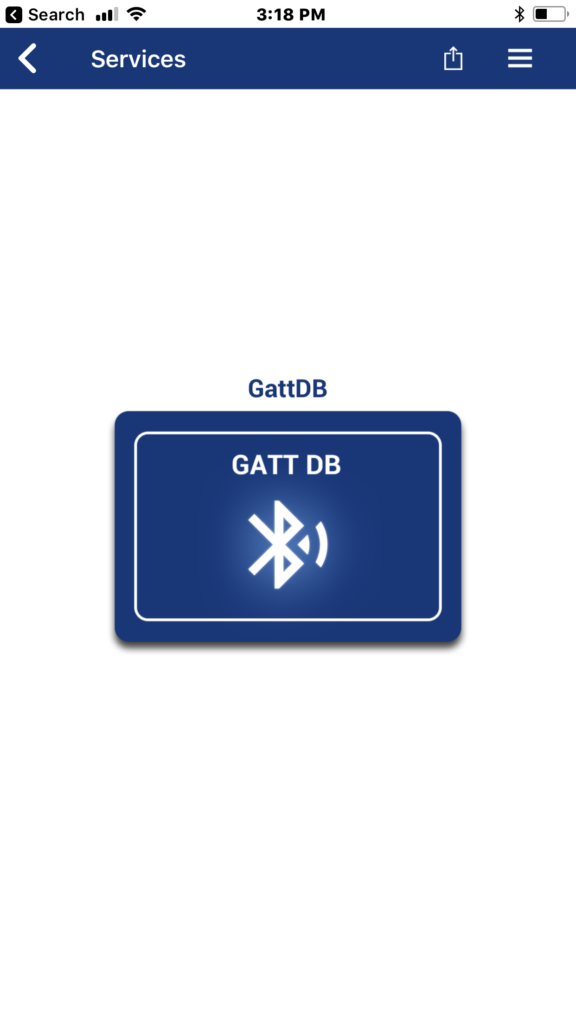
Click on the “Unknown Service”
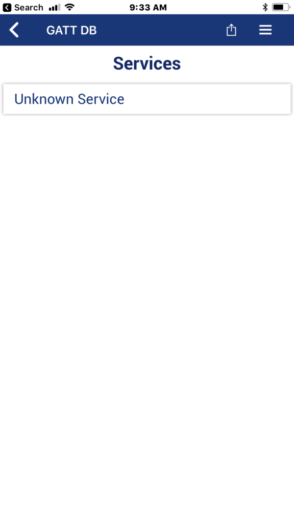
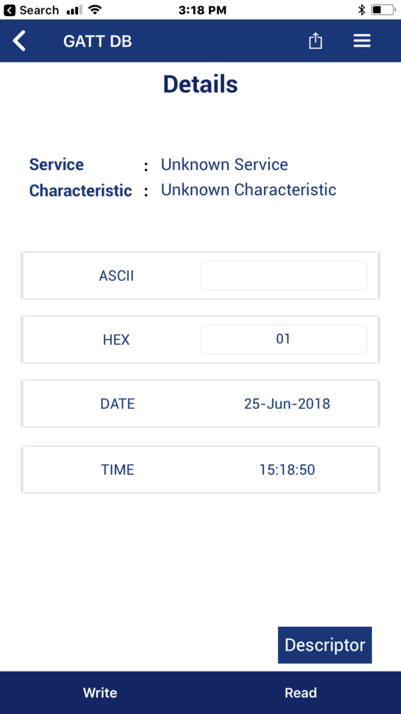
Click on the second characteristic. (we know that is the one because it is Read and Notify)
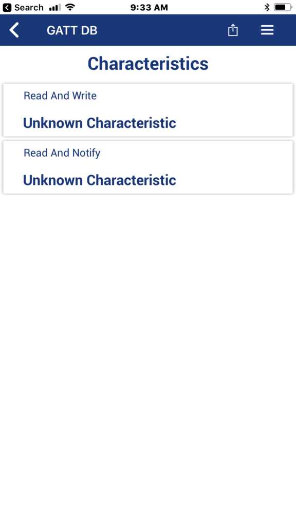
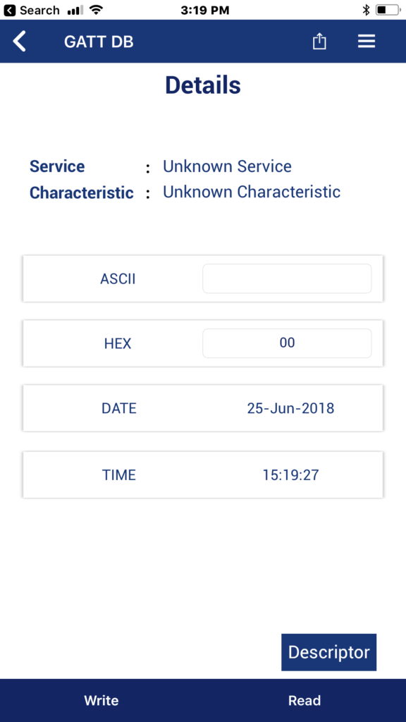
Now you can press “Read”
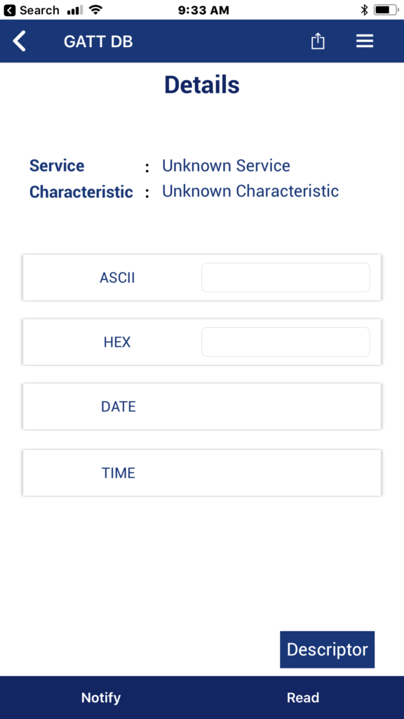
After clicking the read button and you can see that the value is 0x01 (because you are not pressing the button). If you were pressing it you would see 0x00
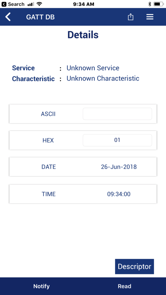
Now press Notify and you should see the value change each time you press the button


