WICED Bluetooth Using the CYW20719
#
Title
Comment
0
A Two Hour WICED Bluetooth Class
WICED Bluetooth Using the CYW20719 in all its glory
1
Resources
Links to all of the Cypress WICED information including videos, application notes etc.
2
Your First Project
Making Hello World & the Blinky LED
3
The Super Mux Tool
Learning about platforms and the Super Mux Tool
4
Snips
Using the example projects to learn Bluetooth
5
Bluetooth Designer
Using the tool to customize a project and get going fast
6
The CCCD & Notification
Writing back to the Central
7
Advertising Beacon
Building a beacon project to advertise your custom information
8
Scanner
Viewing the world around you
9
Bluetooth Classic SPP
Using the Serial Port Profile to Transmit Lots of Data
Source code:
- git@github.com:iotexpert/wiced_bt_intro.git
- https://github.com/iotexpert/wiced_bt_intro
Summary
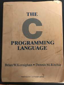
For our first project, I am going to stand on the shoulder of giants. In 1978, Brian Kernighan and Dennis Ritchie published “The C Programming Language”. Here are pictures of my copy.
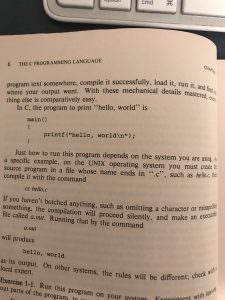
The reason you do “Hello, World” is that you want to make sure that your compiler chain, programmer etc are all working correctly with something that is super simple. The only change that I will make to their classic program is to add the “Blinking LED” which is the embedded developers version of “Hello, World”.
The concepts that I want to show in this lesson are.
- How to make a new project – makefile.mk, <appname>.c
- How NOT to make a new project
- How to create a “Make Target”
- CYW920719Q40EVB01 Development Kit
- WICED PUART and WICED HCI UART
- How to start the bootloader
- Where the documentation resides for the WICED 20719 hardware abstraction layer
- WICED uses ThreadX RTOS
To make this first project the steps are:
- Make a new folder called wiced_bt_class in the Apps Folder
- Make a new folder called L2_HelloWorld in the wiced_bt_intro Folder
- Create a new file called L2_HelloWorld.c
- Create a new file called makefile.mk
- Add the code to print HelloWorld & blink the LED to L2_HelloWorld.c
- Add the secret incantation to makefile.mk to build the project
- Create a “Make Target”
- Connect the development kit to your computer
- Attach a serial terminal to the PUART
- Run the Make Target to Build and Program
Lets do this!
DO NOT DO File->New Project
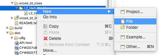
I always hate to start with a negative statement… but DO NOT make a file project by doing File->New Project. This is used for creating a new Eclipse project, not a new WICED Studio project. In WICED Studio we use the make external build system. If you do File->New Project all hell is going to break loose. So don’t do any of the things on this menu:

Hello World & Blinking LED
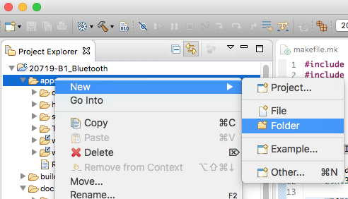
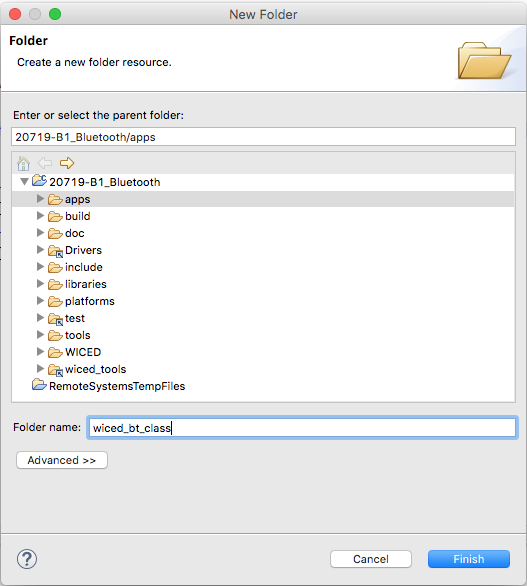
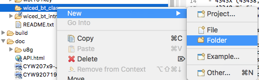
Now lets get on with making a WICED Studio Project. First create a new folder to hold the projects for the Class in the “Apps” folder by right-clicking and selecting New->Folder
Give it the name “wiced_bt_class”
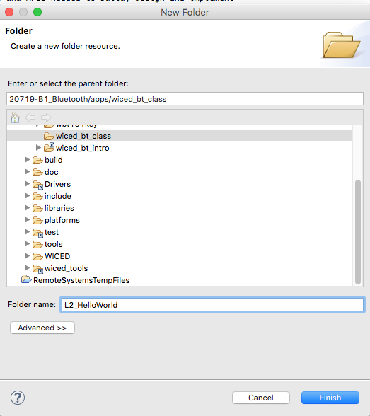
Create a folder to hold the first project called L2_HelloWorld
Call the folder L2_HelloWorld
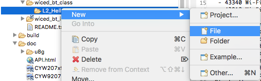
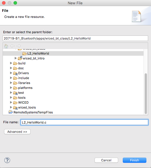
Make a new file called L2_HelloWorld.c by right clicking on the L2_HelloWorld folder and selecting New–>File
Give it the name L2_HelloWorld.c
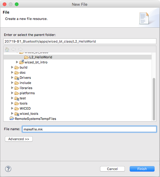
Make a new file called makefile.mk by right clicking on the L2_HelloWorld directory and selecting New->File
and giving it the name makefile.mk
Add some code to the L2_HelloWorld.c
#include "wiced.h"
#include "sparcommon.h"
#include "wiced_platform.h"
#include "wiced_rtos.h"
#include "wiced_hal_gpio.h"
#include "wiced_bt_trace.h"

APPLICATION_START()
{
    wiced_set_debug_uart(WICED_ROUTE_DEBUG_TO_PUART);

    WICED_BT_TRACE("Hello, World\n");
    while(1)
    {

        WICED_BT_TRACE("Setting 0\n");
        wiced_hal_gpio_set_pin_output(WICED_GPIO_PIN_LED_2,0);
        wiced_rtos_delay_milliseconds(500,KEEP_THREAD_ACTIVE );
        WICED_BT_TRACE("Setting 1\n");
        wiced_hal_gpio_set_pin_output(WICED_GPIO_PIN_LED_2,1);
        wiced_rtos_delay_milliseconds(500,KEEP_THREAD_ACTIVE );
    }
}
Add the secret incantation to the makefile.mk
#
# Lesson 2 - Hello, World
#
APP_SRC +=  L2_HelloWorld.c

C_FLAGS += -DWICED_BT_TRACE_ENABLE
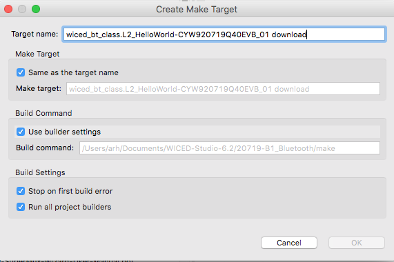
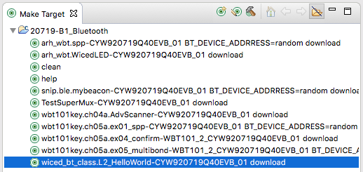
Create a make target
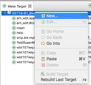
The make target has a VERY specific format. It is:
directory.directory.appname-platform download
In our case we have all of our projects in a directory called “wiced_bt_class”. Then we have a directory called “L2_HelloWorld” which holds the exact project. And our platform name is “CYW920719Q40EVB_01”
Connect the Development Kit To Your Computer
When you plug in your development kit, it will USB enumerate a TWO serial ports. One of the serial ports (the first one) is called the “WICED HCI UART”. The second serial port is called the “WICED Peripheral UART” (this is often abbreviated “PUART”)
One of the key things that the WICED HCI UART is used as is a UART to download new code to the bootloader.
The PUART is used as a general purpose serial port. When we call this function it causes all of our “WICED_BT_TRACE” outputs to go to the the PUART.
wiced_set_debug_uart(WICED_ROUTE_DEBUG_TO_PUART);
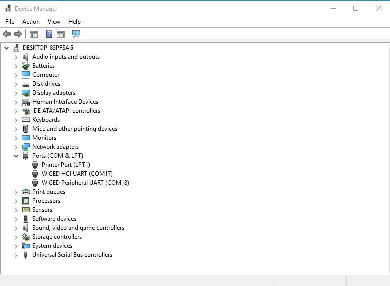
You can see these two UARTs on a PC by running the device manager.
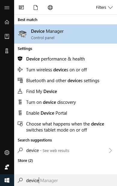
You can see COM17 is the “WICED HCI UART” and COM18 is the “WICED Peripheral UART”
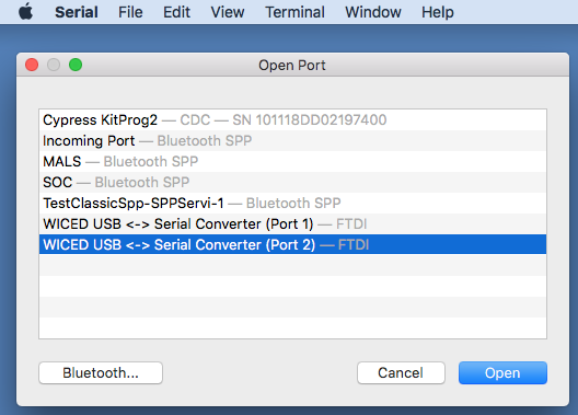
On my Mac I use the program “Serial” which I downloaded from the App Store.
When I run Serial and then to open a Port
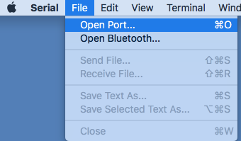
You can see the two UARTs.
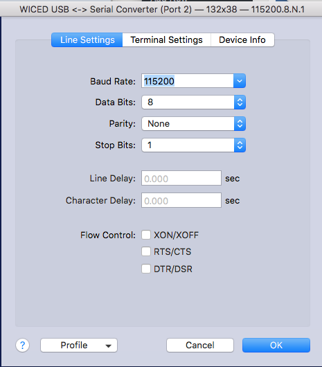
In order to see the output I will connect to the port with the settings
- 115200 Baud
- 8-n-1 (Data bits, Parity, Stop Bits)
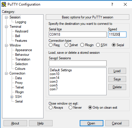
With my PC I typically use Putty (remember it was COM18 from the screen above)
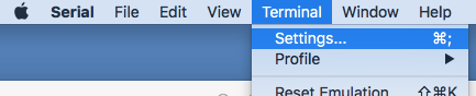
On the Mac program serial you can configure it with Terminal->Settings
Program your Development Kit
In the Make Target window you should see a bunch of “targets”. You probably have a bunch more targets, which came in your installation of WICED Studio by default, but I deleted a bunch of them so I could just see the ones that I created.
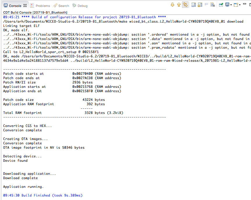
To build and program your project, double click the make target we made before.
When you look in the console you should see something like this:
And when you look at your serial terminal you will see this:
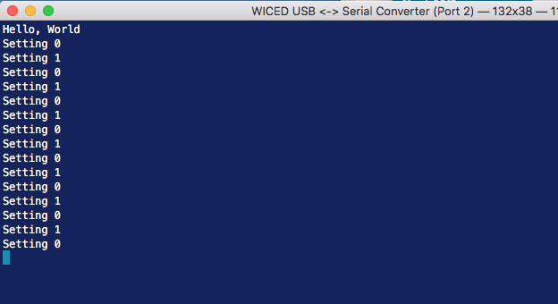
And you should also see the blinking LED!!!
Start the Bootloader
If you get this message there are three posibilites
- The kit isn’t plugged in
- The driver didn’t install properly
- The bootloader wont start
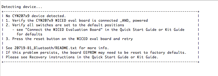
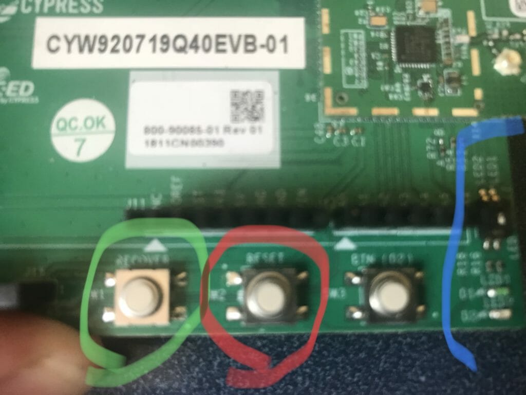
Check the first two… and if that doesnt work then what this means is that the bootloader is not listening on the WICED HCI UART. In order to fix this you need to press reset and hold down the button called “Recover”. Then release the reset, then release the recover button. What does this do? Simple, when the chip comes out of reset, if the recover button is pressed, the chip starts the bootloader instead of the main application.
Here is a picture of the bottom corner of the board. The button circled in Green is the “Recover”. The button in Red is “Reset” and the Blue surrounds the LED circuit.
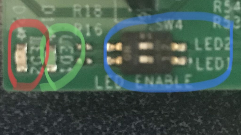
The two LEDs are labeled LED1 and LED2. LED2 is the Red one, LED1 is the Green one. The dip switches circled in Blue connect or disconnect the LEDs from the CYW20719. In my case you can see (barely) that the switch is set to On. Both of these LEDs are active LOW (0 turns them on)
10 Comments
Well done! These lessons for WICED Ble are very useful. It helps the transitions from PSoC 4 BLE to this new toolchain.
Could I utilize CYBT-343026-EVAL kit to follow through or is the specified evaluation kit a requirement?
That module has the 20706 … the bluetooth is very similar and should work fine…. the peripherals are a bit different and you will need to sort that out.
I followed all the steps but when I tried to make the target, the following error showed up “:0:16: error: invalid suffix “_spar_crt_setup” on integer constant”. Any suggestions? Thanks for the course!
I dont know. Can you please post on the Cypress community.
Very good job done, Alan!
Would be quite helpful if you can add some lesson for manipulating GPIOs direct from registers / memory as neither memory map is available for CYW20719 nor API has enough functionality to perform some of very common GPIO tasks.
OK… I could do that… do you have some specific things that you are interested in?
Couple ideas as per your request:
The functionality I’m missing (guess others too) is the batch check / set couple GPIOs. For example I could check just with a simple operation (I0_values_register & IOs_of_interst_mask ) if any of the multiple buttons (represented in IOs_of_interst_mask ) are pressed/released – instead of coding multiple wiced_hal_gpio_get_pin_input_status ().
Also with same approach to enable/disable interrupts or certain IOs trough config registries
And the last functionality that comes in my mind right now – config/ (read config) of IOs as outputs, because currently there is a bug in WICED – wiced_hal_gpio_configure_pin or maybe in wiced_hal_gpio_get_pin_config and when try to configure a pin as output , next check with wiced_hal_gpio_get_pin_config return it as input. https://community.cypress.com/thread/47164
Regards
Yes… all of that code is in the ROM and probably isn’t going to change. But I understand you pain.
Alan
Congrats for the good tutorials. Could you, please, consider to add some additional information regarding memory map/registers of CYW20719 as such information is not available neither in the spec sheets nor in the tutorials published so far. I am interested currently on the GPIO registers ….
Thanks
Thanks for the nice words….
For the chips which came from Broadcomm we have not generally released the register maps… unfortunately. All of the PSoCs + all of the new wireless chips will have that data. I know that this isn’t a very satisfactory answer but that is the deal.
Alan