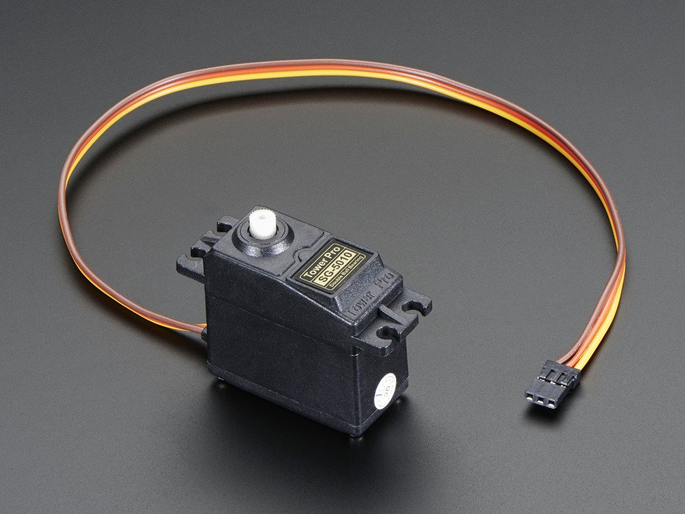
As I talked about in my previous post I am going to use a PSoC as a servo motor controller as well as a CapSense UI. The problem is that I wanted a really easy way to plug the servo motors into the PSoC. It seems like all of the servos have a 3 wire interface, Power, Ground and PWM. Here is a picture that I got from Adafruit’s website.
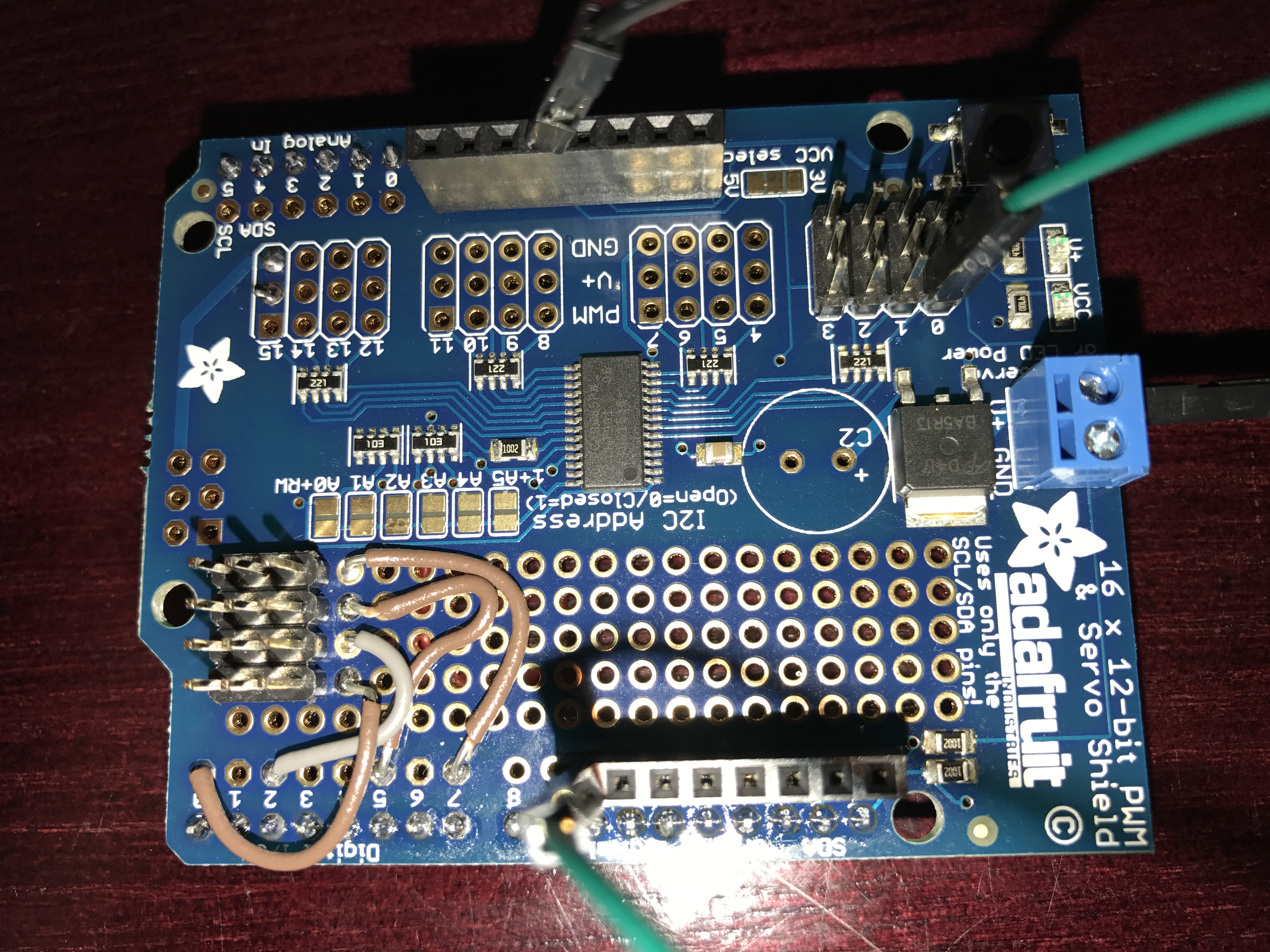
I was originally hoping that I could connect that servo directly to the PSoC, drive a ‘1’ to the power and a ‘0’ to the ground and PWM to the third input. But, it turns out that these things suck some serious juice (100+ma?) so driving the power with the PSoC isn’t in the cards. Given them amount of time that I had left, there was not time for a custom board, so I was in the situation of using a breadboard with wires all over the place which is ugly and a bit of a pain. However, on Thursday I thought that I might find a “Servo Shield” and sure enough there are a number of them out there including this one which I got from Adafruit. The problem is this shield uses a 16 channel I2C –> PWM driver from NXP. I am not a fan of doing things with peripheral chips that PSoC can do for itself. But, when I got the shield this morning in the mail there was a cool prototyping area on the shield. So, I made my own header for connecting to the PSoC. Here is the front:
And here is the back:
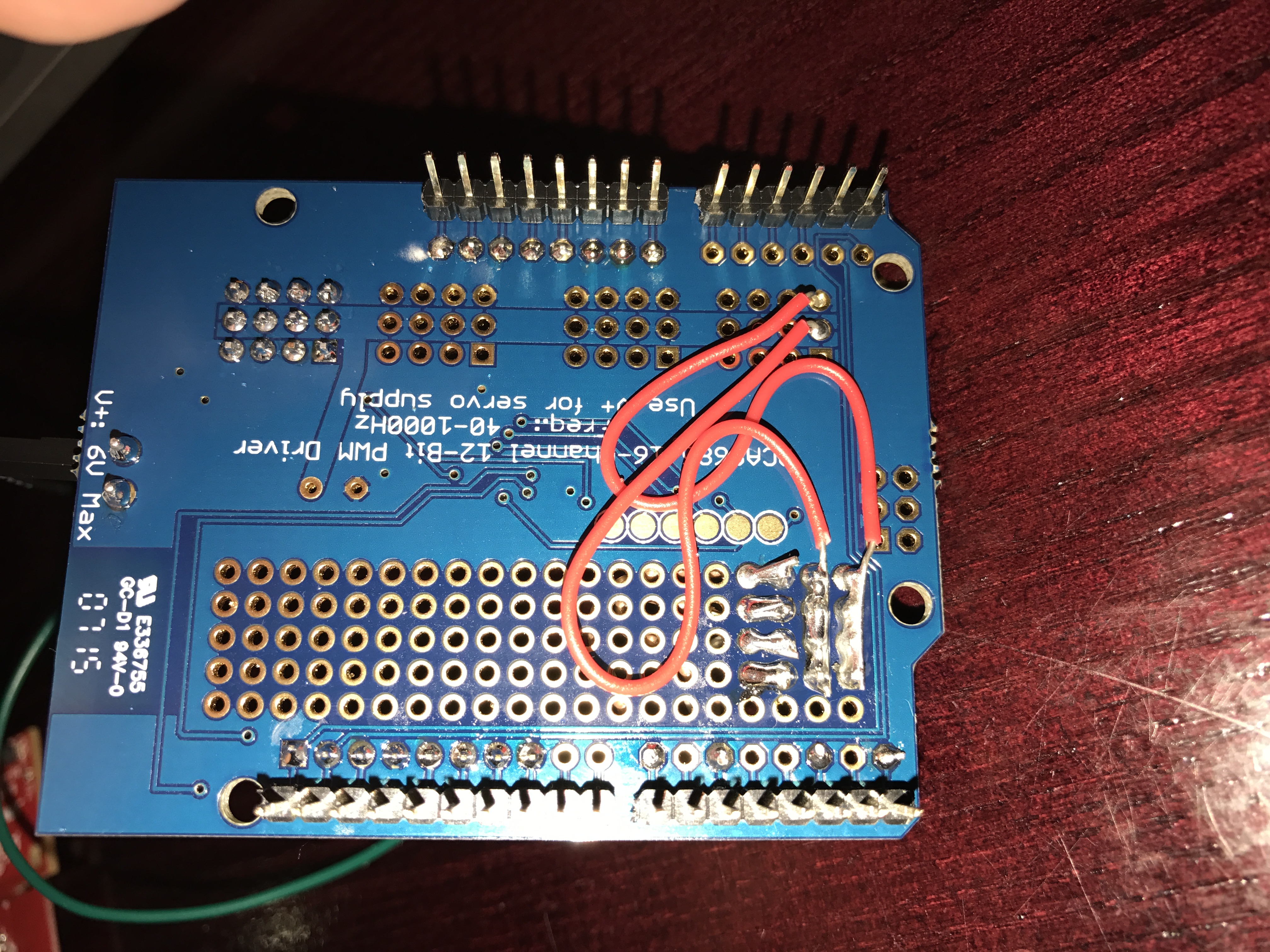
You can see that I shorted the whole row of ground together with a big blog of solder and wire. I did the same thing with the power (the middle row). Then I made a wire from each of the 4 PWMs pins to a good place on the PSoC (which I could drive the pins directly from one of the TCPWMs)

The board worked great on my bench. The only thing that I have done which is VERY questionable is that I wired the power supply for the system directly to the V5.0 aka VBUS… which I suppose will get me through the conference, but is probably a bad idea (the green wire in the top picture)
As I was flying to Detroit I thought that I might try to see how the I2C->PWM worked… so I read the data sheet for the NXP PCA9685. It turns out that the chip is pretty cool. You can set the output frequency by setting a divider value in one of the registers (oxFE). The number you set is val=round(25e6/(4096*rate)) – 1. That means for me to get 50hz to drive the motors I need to set the divider to 121. Then to set the duty cycle each output has a 12-bit PWM where you can set “LED ON” and a “LED Off” count. For instance to get a 25% duty cycle you can set the On to 0 and the off to 1024.
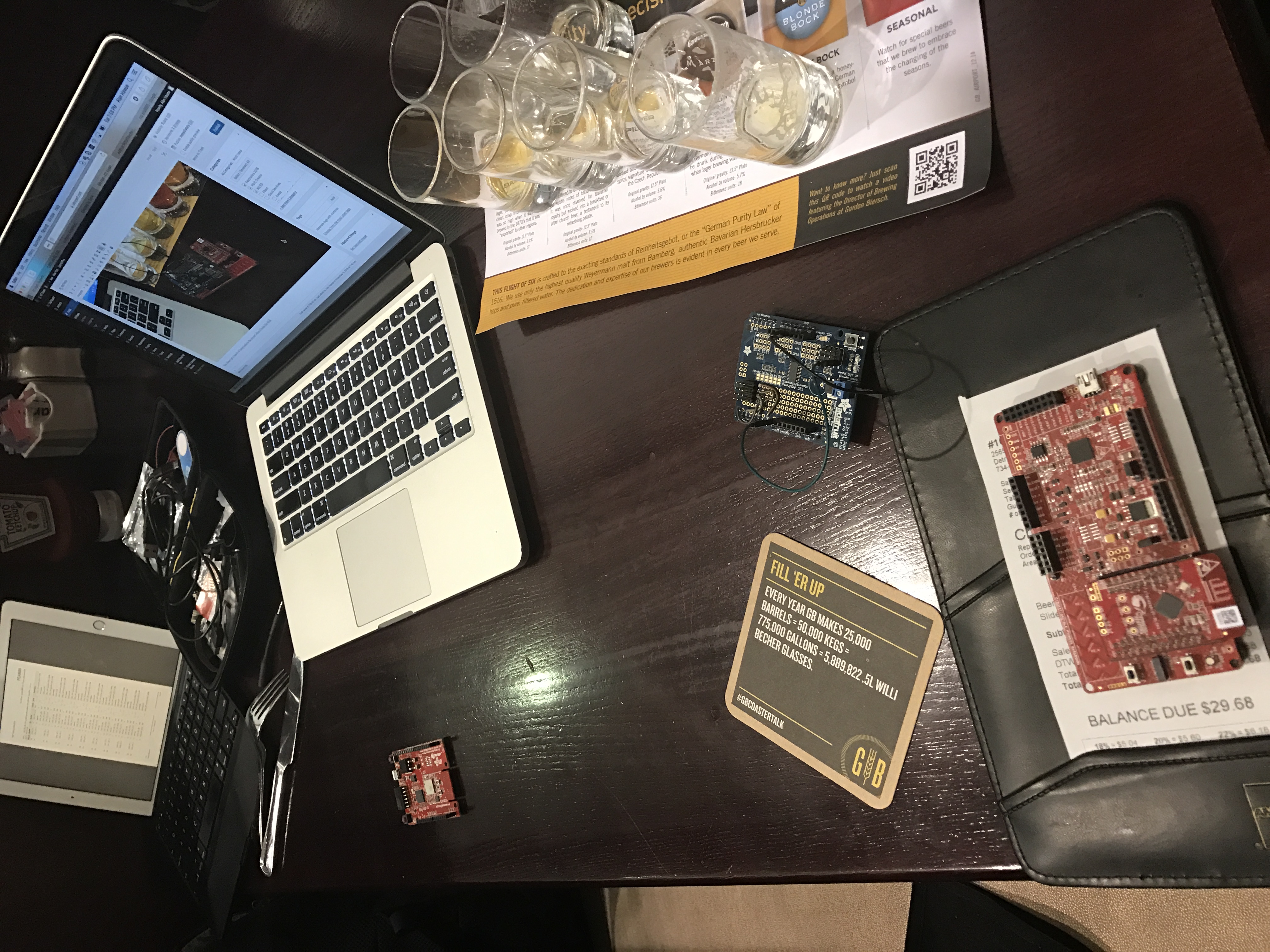
After I got off the airplane in Detroit I went to get some “dinner” and I wanted to try out the shield so I hooked it up:
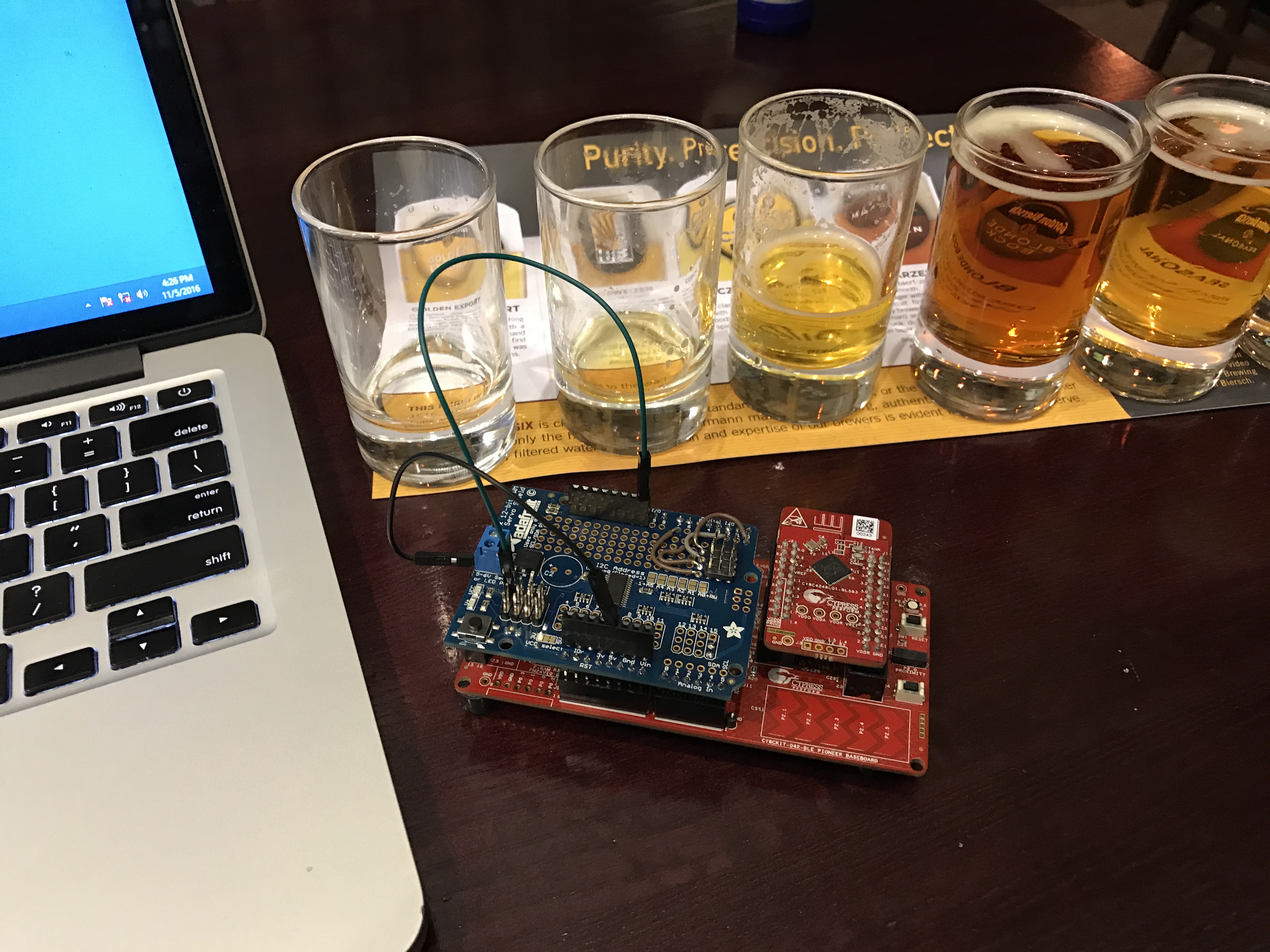
You always get a bunch of funny looks in the airport when your table looks like this:
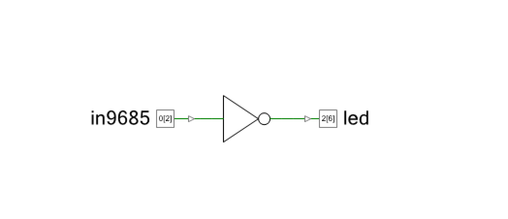
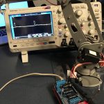
 This left me with only one problem. How to drive the shield PWMs onto something that I could see… I didnt pack my Tek in my carry on (though I suppose I could have used one of those little scopes). But, I digress. What I decided to do is make the PSoC echo an input onto on output pin that was connected to an LED. So, I drew this schematic. This can only be done in with a PSoC because I used a logic gate in the UDB to flip the 9685 PWM from Low to High so that my active low LED would work right.
Next I fly to Charles De Gaul, the suckiest airport in the first world. What will I do on the airplane there? I don’t, but given those empty beer glasses I may sleep. More to follow when I get to Germany.
No comment yet, add your voice below!