Summary
In the last Article I talked about the GE Megahackathon. One of the groups at the event got interested in using a CY3280 MBR3 to send signals via a WICED CYW943907 to the Particle IO server which was connected to a Particle Photon. I helped them with the implementation and thought that it would be useful to show here.
Cypress CY3280 MBR3
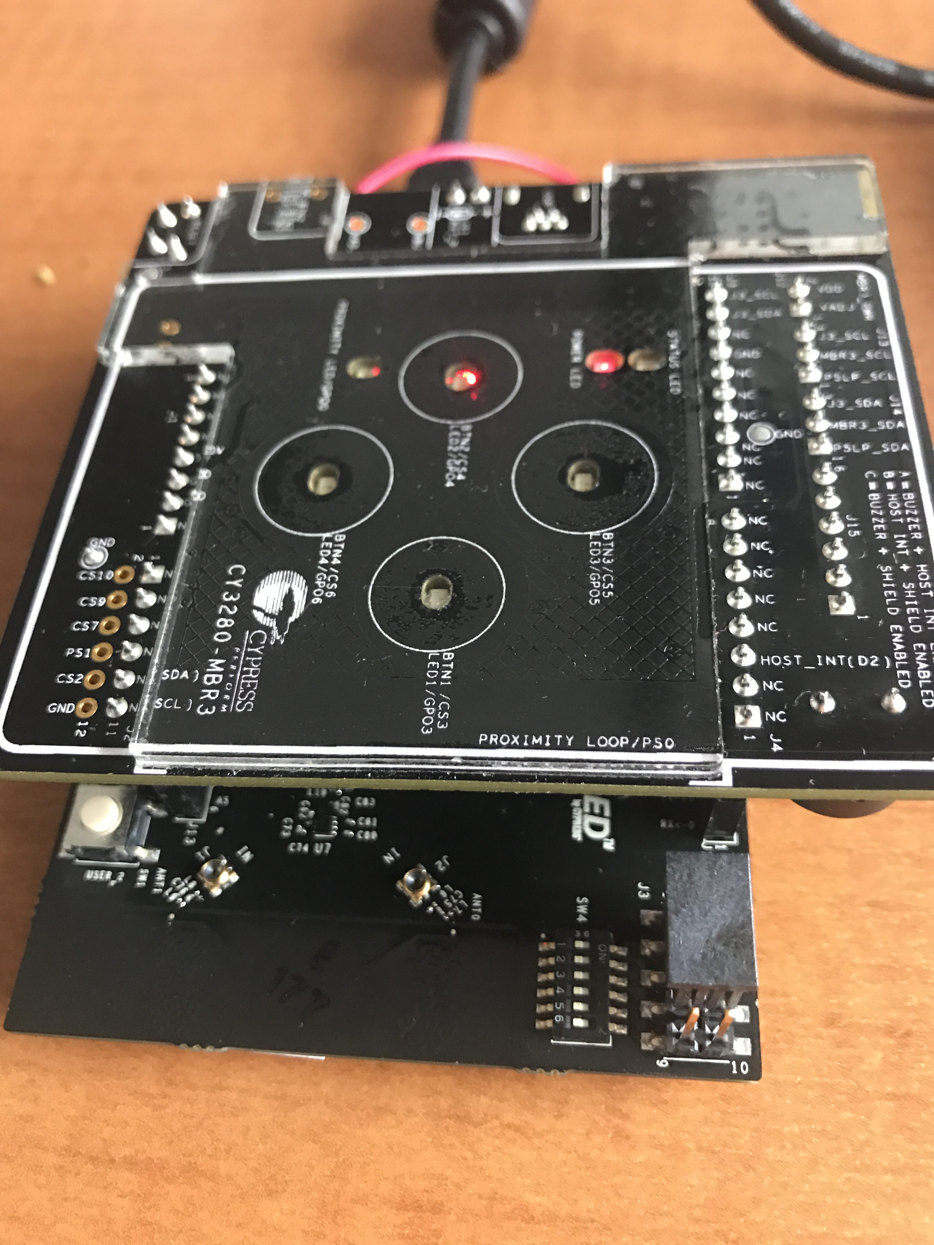
The CY3280 MBR development kit is a CapSense demonstration kit that shows the Mechanical Button Replacement 3 chip. It features 4 CapSense buttons with LEDs, a proximity sensor, and a buzzer. It is connected to another MCU via the Arduino pins. of the WICED CYW943907. The device sits on the I2C bus and acts as an I2C Slave. You configure it using EZ Click.
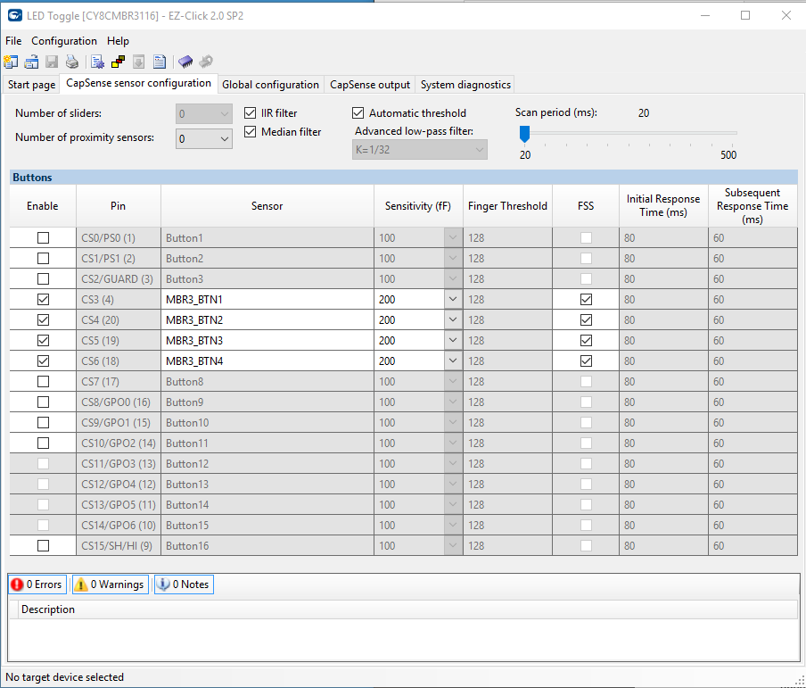
When you run EZ Click you can setup the configure the internal registers of the MBR3 to make the board act like a bunch of different things. In this case I turned on
- The MBR buttons 1-4 (you can see them in the picture above)
- The Flanking Sensor rejection which makes it so that you can only press one button at a time.
- All of the automatic tuning features.
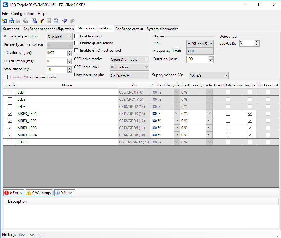
Once the main CapSense is configured, I moved to the other part of the configuration where I setup
- The 4 LEDs to toggle and be full brightness when on
- The buzzer to buzz for 100ms at 4kHz when something happens
- The host interrupt pin as CS15/SH/HI. This made the Arduino pin D2 be an interrupt when something happened so that WICED would poll the MBR3
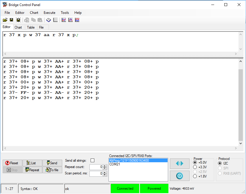
Once these settings were all done, I downloaded the firmware configuration via the KitProg USB connector. Then I tested it using the bridge control panel which I have shown you a bunch of different times in the past. The MBR3 acts as an I2C slave. To find out what the state of the buttons are you need to read register 0xAA. The only little trick is that the chip goes to sleep to save power. In order to wake it up you need to send an I2C transaction, which ends up getting NAK’d. But the next transaction you send will be ACKd. In the screenshot below you can see that I tried two of the buttons (0x08 and 0x20)
One problem that I had is that the power system of this board is setup to take 5V from the Arduino base board but the WICED development kit gives only 3.3v. Here is a picture of the power system from the MBR3 schematic.

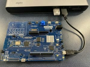
The MBR3 can run on 3.3Vs. In fact it can run all the way down to 1.7v and up to 5.5v, but for some reason (which I can’t remember) we made the board only work with 5.0v. To fix this problem I removed J12 and then wired a wire from the 3.3V Arduino pin. The wire is soldered onto the 3.3v pin, but has a female connector on the other side so that it can be plugged into J12. Here is a picture:

The last thing that I needed to do was move the jumpers to position “A” which made the host interrupt pin be connected to D2, and move the I2C jumpers so that the MBR3 was connected to the Arduino instead of the P5LP kitprog. You can see that in the J3_scl and J3_sda in the picture above.
WICED CYW943907
The CYW934907AEVAL1F is an development kit for the Cypress 43907 MCU+WiFi module. The WICED CYW943907 board can do dual band (2.4 and 5Ghz), 802.11 a/b/g/n, Ethernet and a whole bunch of other stuff.

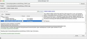
The first firmware that I wrote in WICED Studio:
- Sets up an ISR to unlock a semaphore when the interrupt occurs
- Initialized WICED_GPIO_9 to be an input and connected to an ISR … this is also known as Arduino D2
- Setup the I2C Master Hardware in the 43907
- Wait for a semaphore (from the ISR)
- Read the I2C register 0xAA from the MBR
The only trick in the firmware is that I read the I2C with a “do” loop until I get a valid result, meaning that the MBR3 has woken up.
#include "wiced.h"
#define I2C_ADDRESS (0x37)
#define BUTTON_REG (0xAA)
wiced_semaphore_t buttonPress;
/* Interrupt service routine for the button */
void button_isr(void* arg)
{
wiced_rtos_set_semaphore(&buttonPress);
}
/* Main application */
void application_start( )
{
wiced_init(); /* Initialize the WICED device */
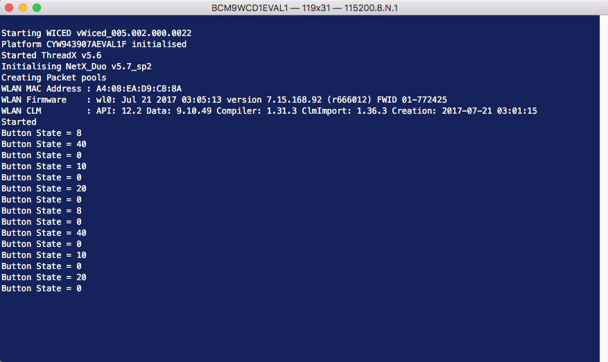
WPRINT_APP_INFO(("Started\n"));
wiced_result_t result;
wiced_rtos_init_semaphore(&buttonPress);
// WICED_GPIO_9 is the MBR3 Interrupt Pin
wiced_gpio_init(WICED_GPIO_9,INPUT_PULL_UP);
wiced_gpio_input_irq_enable(WICED_GPIO_9, IRQ_TRIGGER_FALLING_EDGE, button_isr, NULL); /* Setup interrupt */
/* Setup I2C master */
const wiced_i2c_device_t i2cDevice = {
.port = WICED_I2C_2,
.address = I2C_ADDRESS,
.address_width = I2C_ADDRESS_WIDTH_7BIT,
.speed_mode = I2C_STANDARD_SPEED_MODE
};
wiced_i2c_init(&i2cDevice);
/* Tx buffer is used to set the offset */
uint8_t tx_buffer[] = {BUTTON_REG};
uint8_t buttonStatus;
while ( 1 )
{
wiced_rtos_get_semaphore(&buttonPress,WICED_WAIT_FOREVER);
// Do this until the MBR3 is alive. It goes into deep sleep and wakes when you
// send the first command.
do {
result = wiced_i2c_write(&i2cDevice, WICED_I2C_START_FLAG | WICED_I2C_STOP_FLAG, tx_buffer, sizeof(tx_buffer));
}
while(result != WICED_SUCCESS);
result=wiced_i2c_read(&i2cDevice, WICED_I2C_START_FLAG | WICED_I2C_STOP_FLAG, &buttonStatus, sizeof(buttonStatus));
WPRINT_APP_INFO(("Button State = %X\n", buttonStatus)); /* Print data to terminal */
}
}
Once that is programmed I program and test the firmware.
In the next article I will modify all of this firmware and make the WICED CYW943907 send data via HTTP to the Cloud.

No comment yet, add your voice below!