WICED Bluetooth Using the CYW20719
#
Title
Comment
0
A Two Hour WICED Bluetooth Class
WICED Bluetooth Using the CYW20719 in all its glory
1
Resources
Links to all of the Cypress WICED information including videos, application notes etc.
2
Your First Project
Making Hello World & the Blinky LED
3
The Super Mux Tool
Learning about platforms and the Super Mux Tool
4
Snips
Using the example projects to learn Bluetooth
5
Bluetooth Designer
Using the tool to customize a project and get going fast
6
The CCCD & Notification
Writing back to the Central
7
Advertising Beacon
Building a beacon project to advertise your custom information
8
Scanner
Viewing the world around you
9
Bluetooth Classic SPP
Using the Serial Port Profile to Transmit Lots of Data
Source code:
- git@github.com:iotexpert/wiced_bt_intro.git
- https://github.com/iotexpert/wiced_bt_intro
Summary
You probably noticed and wondered “Why did he use WICED_LED_2 instead of WICED_LED_1”? The answer to that question is that by default the CYW920719Q40EVB_01 is setup with WICED_LED_2 enabled as a GPIO and WICED_LED_1 used for another purpose. But to what purpose? In this lesson we will answer the questions:
- What are the default pins?
- How do you use the SuperMux tool?
- How do you use a PWM?
To do this we are going to copy the L2_HelloWorld project and add a PWM to drive the Green LED also known as WICED_LED_1.
The steps we are going to follow are
- Copy the L2_HelloWorld to start a new project called L3_SuperMux
- Rename L2_HelloWorld.c
- Fix the makefile.mk for the updated source file
- Create a new make target
- Program to make sure everything is still working
- Look at the platform files for CYW920719Q40EVB_01
- Run the SuperMux Tool
- Delete the SPI Slave_1 From the SuperMux
- Add an LED to the SuperMux
- Configure the LED to P28
- Apply the SuperMux configuration
- Look at the new files added to the project
- Look a the makefile.mk
- Look L3_SuperMux_pin_config.c
- Update L3_SuperMux.c to have correct includes
- Update L3_SuperMux.c to start the clock, pin and PWM
- Program the project
- Look at the Hardware Abstraction Layer Documentation
Copy L2_HelloWorld –> L3_SuperMux
Instead of starting from a blank project. Lets make a copy of the L2_HelloWorld project. If you right click on the L2_HelloWorld folder and select copy
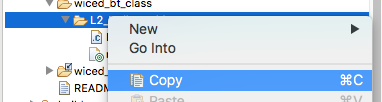
Then click on the “wiced_bt_class” folder and select paste.

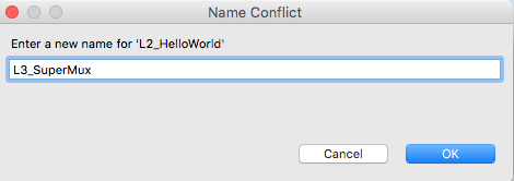
WICED Studio will then complain that you already have a directory called “L2_HelloWord” and give you the opportunity to rename it. Call the new project “L3_SuperMux”
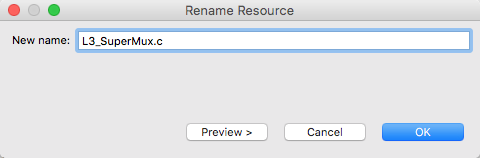
Now you need to rename the L2_HelloWorld.c to be L3_SuperMux.c. Right click on the L2_HelloWorld.c and select rename

Then give it a new file name… like L3_SuperMux.c
Double click makefile.mk and edit it. You need to change the comment, and the name of the APP_SRC source file.
#
# Lesson 3 - SuperMux
#
APP_SRC +=  L3_SuperMux.c

C_FLAGS += -DWICED_BT_TRACE_ENABLE
Create a make target for this project by right clicking the L2_HelloWorld Make Target, then selecting “New”
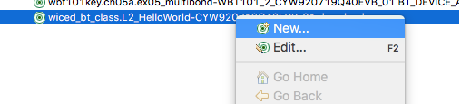
That will make a new target… and it will bring up this dialog box. Notice that it named the target “Copy of …”
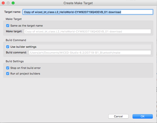
Fix it to be “L3_SuperMux” like this:
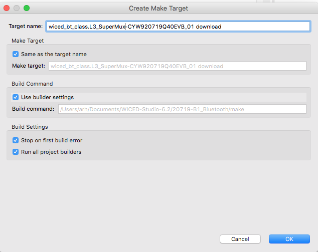
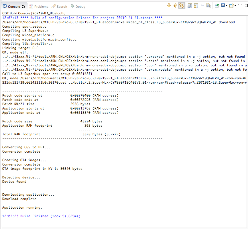
You should now have an exact copy of L2_HelloWorld, in the project L3_SuperMux. Double click the make target and make sure that things are still working. When you build you should get this. Don’t forget to “Start the Bootloader” if the programming doesn’t work.
Platform Files
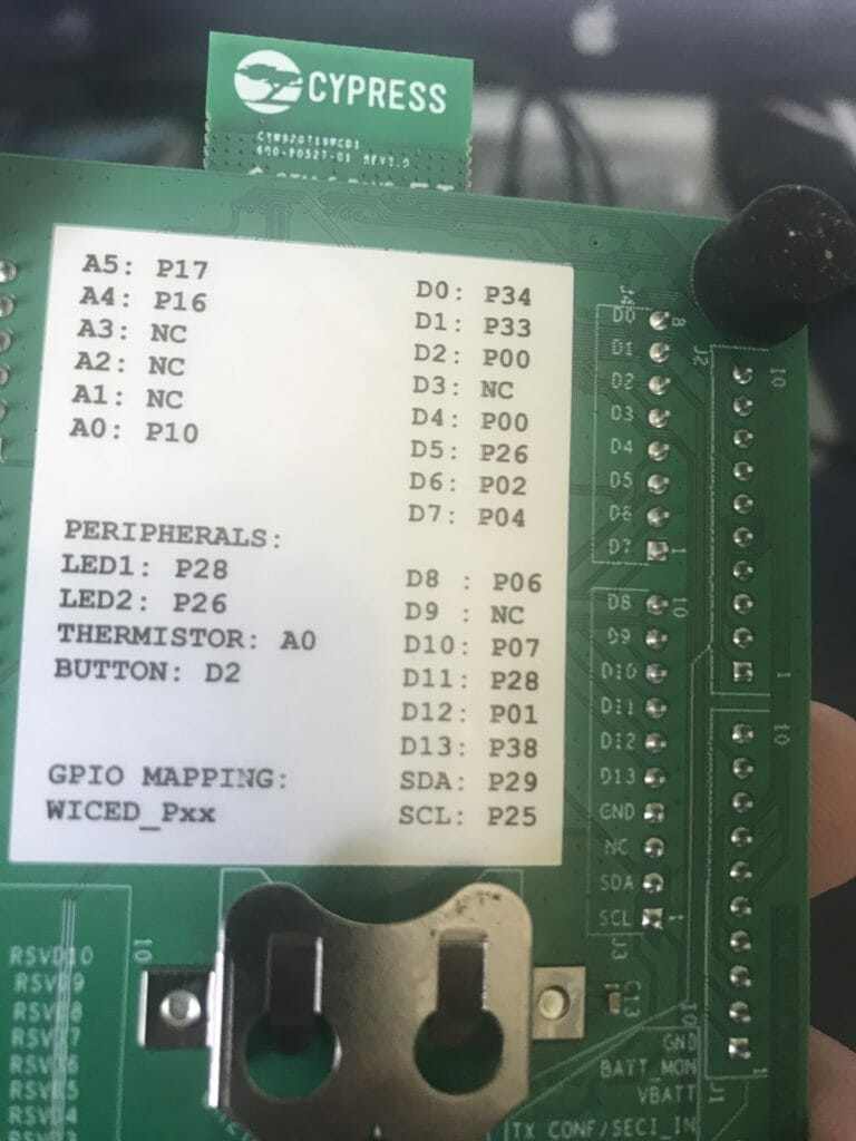
If you look on the back of your CYW920719Q40EVB-01 development kit you will find the exact pin map of this board. On this picture you can see that LED1 is connected to P28
In WICED Studio, the world “Platform” is just another word for Board Support Package. Basically all of the configuration required to build the firmware for a specific board. If you click on platforms you will find a directory for the CYW920719Q40EVB. All of the default configuration for the pins are located in the file “wiced_platform_pin_config.c”
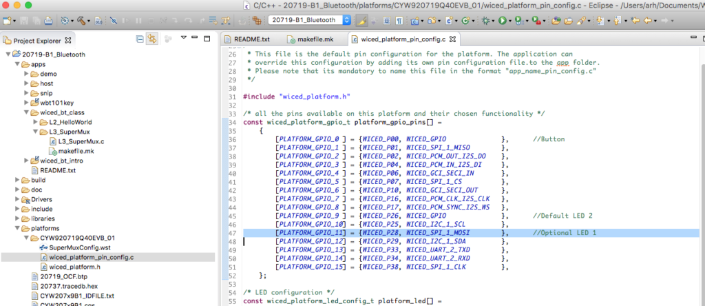
If you look at this file closely, you will see on line 47 that pin P28 is setup as the MOSI of WICED_SPI_1. That isnt a GPIO!!!. And you will see a whole block of code on line 74 that is commented out that COULD configure P28 as a GPIO. But that would require modifying our default platform files, which I dont want to do. Now what? Simple use the SuperMux tool.
/* all the pins available on this platform and their chosen functionality */
const wiced_platform_gpio_t platform_gpio_pins[] =
    {
        [PLATFORM_GPIO_0 ] = {WICED_P00, WICED_GPIO              },      //Button
        [PLATFORM_GPIO_1 ] = {WICED_P01, WICED_SPI_1_MISO        },
        [PLATFORM_GPIO_2 ] = {WICED_P02, WICED_PCM_OUT_I2S_DO    },
        [PLATFORM_GPIO_3 ] = {WICED_P04, WICED_PCM_IN_I2S_DI     },
        [PLATFORM_GPIO_4 ] = {WICED_P06, WICED_GCI_SECI_IN       },
        [PLATFORM_GPIO_5 ] = {WICED_P07, WICED_SPI_1_CS          },
        [PLATFORM_GPIO_6 ] = {WICED_P10, WICED_GCI_SECI_OUT      },
        [PLATFORM_GPIO_7 ] = {WICED_P16, WICED_PCM_CLK_I2S_CLK   },
        [PLATFORM_GPIO_8 ] = {WICED_P17, WICED_PCM_SYNC_I2S_WS   },
        [PLATFORM_GPIO_9 ] = {WICED_P26, WICED_GPIO              },      //Default LED 2
        [PLATFORM_GPIO_10] = {WICED_P25, WICED_I2C_1_SCL         },
        [PLATFORM_GPIO_11] = {WICED_P28, WICED_SPI_1_MOSI        },      //Optional LED 1
        [PLATFORM_GPIO_12] = {WICED_P29, WICED_I2C_1_SDA         },
        [PLATFORM_GPIO_13] = {WICED_P33, WICED_UART_2_TXD        },
        [PLATFORM_GPIO_14] = {WICED_P34, WICED_UART_2_RXD        },
        [PLATFORM_GPIO_15] = {WICED_P38, WICED_SPI_1_CLK         },
    };

/* LED configuration */
const wiced_platform_led_config_t platform_led[] =
    {
        [WICED_PLATFORM_LED_2] =
            {
                .gpio          = (wiced_bt_gpio_numbers_t*)&platform_gpio_pins[PLATFORM_GPIO_9].gpio_pin,
                .config        = ( GPIO_OUTPUT_ENABLE | GPIO_PULL_UP ),
                .default_state = GPIO_PIN_OUTPUT_HIGH,
            },

// We can use either LED1 or SPI1 MOSI, by default we are using WICED_P28 for SPI1 MOSI,
// uncomment the following initialization if WICED_P28 is to be used as an LED and set PIN
// functionality in platform_gpio_pins as WICED_GPIO

//        [WICED_PLATFORM_LED_1] =
//            {
//                .gpio          = (wiced_bt_gpio_numbers_t*)&platform_gpio_pins[PLATFORM_GPIO_11].gpio_pin,
//                .config        = ( GPIO_OUTPUT_ENABLE | GPIO_PULL_UP ),
//                .default_state = GPIO_PIN_OUTPUT_HIGH,
//            }
    };
SuperMux Tool
The SuperMux tool is a GUI for setting the default configurations of the Pins on the chip. Like all capable MCUs, this chip has PWMs, SPIs, UARTs, GPIOs, I2C, ADCs etc. Each pin on the chip can do a bunch of different functions, but only one at a time. Each pin has a multiplexor in front of it that selects the function of that pin. The SuperMux tool helps you setup the multiplexors for each pin on the chip.
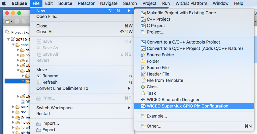
To run the SuperMux tool, first click on your project directory (remember L3_SuperMux). The select File–>New–>WICED SuperMux GPIO Pin Configuration
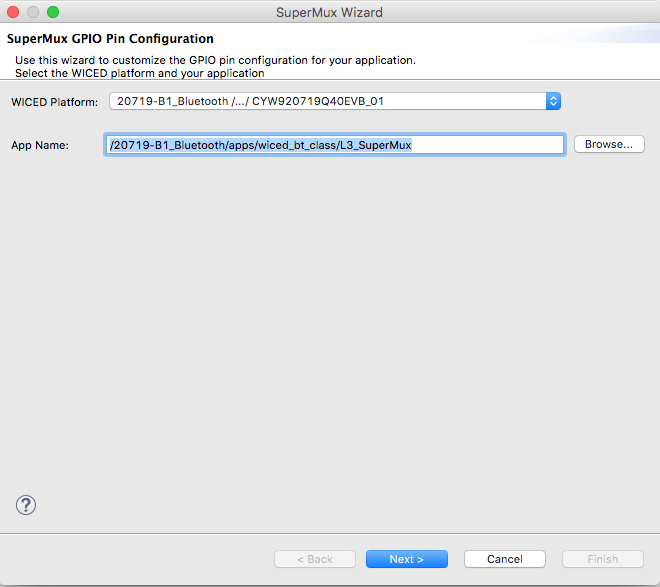
It will ask you which “App Name” you want it to work on. Since we clicked on the L3_SuperMux app, it uses that name by default. Press Next
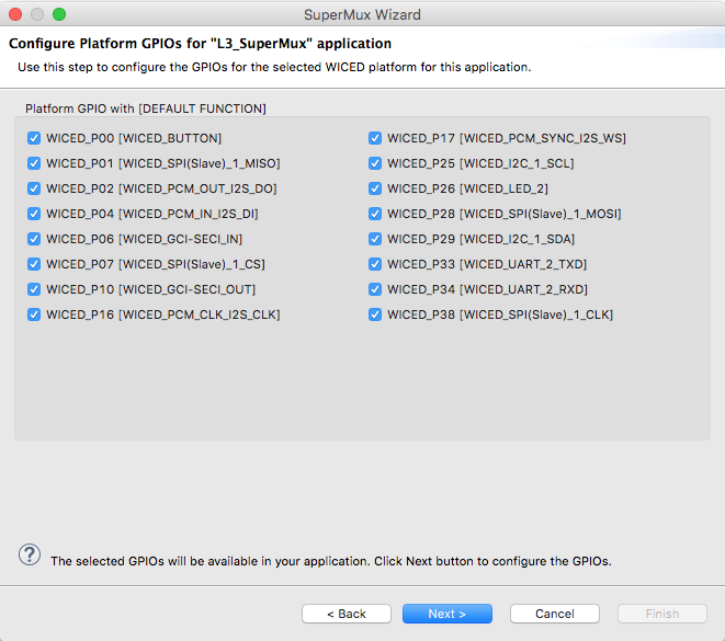
The SuperMux Wizard will give you the opportunity to select which pins you want to configure. It also shows you the default configuration of each of the pins. In this case just press “Next” because we want to configure them all.
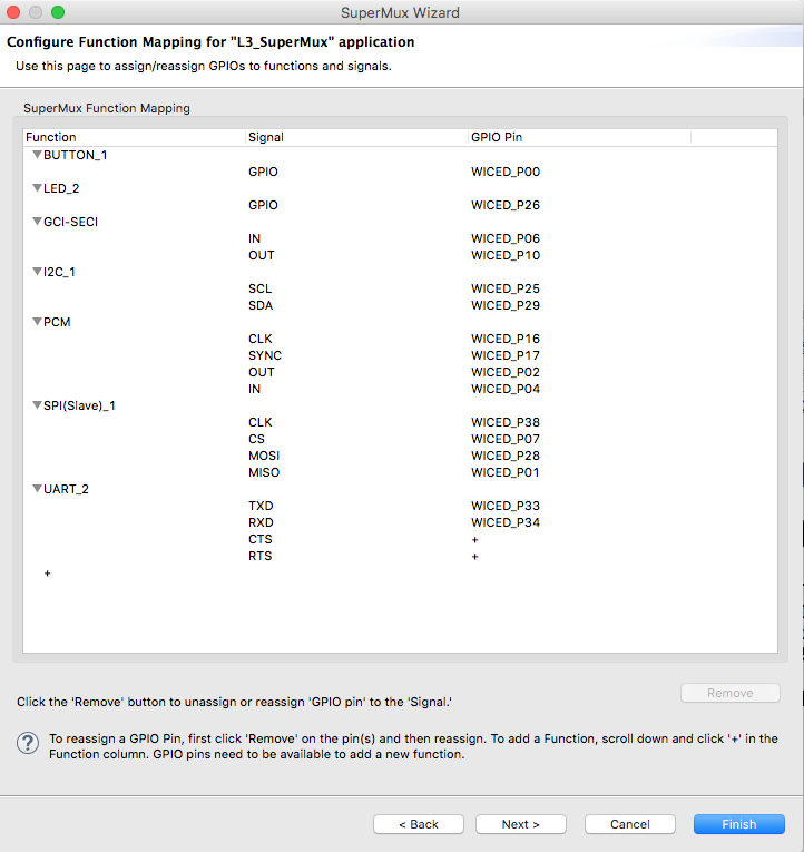
Now you will see the functions of the chip and which pins they are assigned to. Notice that WICED_P28 is assigned as the MOSI of SPI(Slave)_1. We don’t want that.
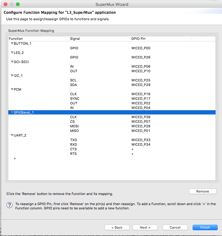
Remove the SPI(Slave)_1 by selecting it and then pressing the “Remove” button
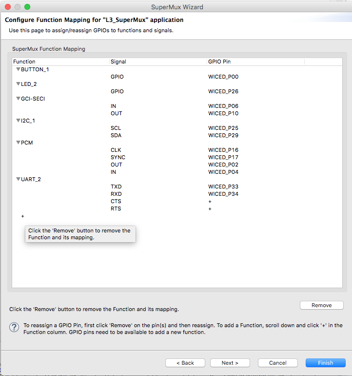
Now your screen will look like this. In order to add a new pin configuration you can press the little “+” at the bottom of the function column.
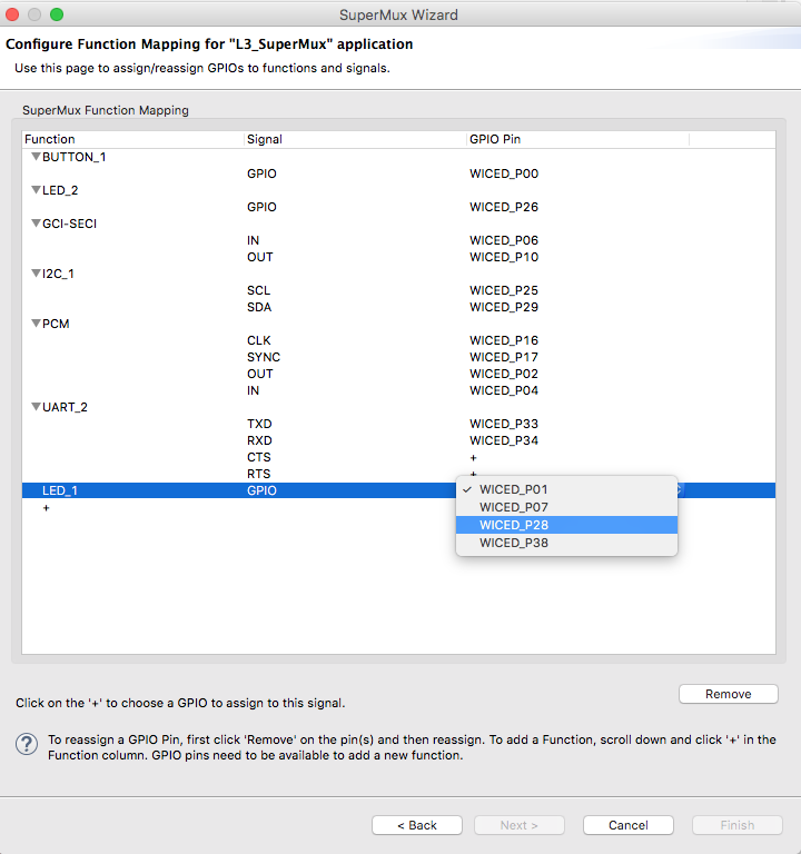
Next press the little “+” button and select LED.

The select which Pin you want assigned to the LED. In this case we want WICED_P28
After you press finish you will notice that it adds a several files to your project. And you notice that it creates a file called “makefile.mk.bak” (which is the backup of the original makefile)
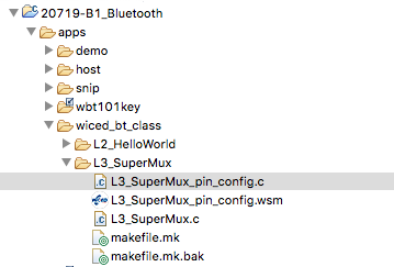
First look at the makefile and notice that it added the “L3_SuperMux_pin_config.c” to the sources and added a CFLAG
#
# Lesson 3 - SuperMux
#
APP_SRC +=  L3_SuperMux.c

C_FLAGS += -DWICED_BT_TRACE_ENABLE
C_FLAGS += -DSMUX_CHIP=$(CHIP)
APP_SRC += L3_SuperMux_pin_config.c
So, what is up with the L3_SuperMux_pin_config.c. OH!!! I See, this is just a replacement for the default platform configuration. Notice that P28 is now a WICED_GPIO and that it is now defined in the LED list.
wiced_platform_gpio_t platform_gpio_pins[]=
	{
		[PLATFORM_GPIO_0]	= {WICED_P00, WICED_GPIO},
		[PLATFORM_GPIO_1]	= {WICED_P02, WICED_PCM_OUT_I2S_DO},
		[PLATFORM_GPIO_2]	= {WICED_P04, WICED_PCM_IN_I2S_DI},
		[PLATFORM_GPIO_3]	= {WICED_P06, WICED_GCI_SECI_IN},
		[PLATFORM_GPIO_4]	= {WICED_P10, WICED_GCI_SECI_OUT},
		[PLATFORM_GPIO_5]	= {WICED_P16, WICED_PCM_CLK_I2S_CLK},
		[PLATFORM_GPIO_6]	= {WICED_P17, WICED_PCM_SYNC_I2S_WS},
		[PLATFORM_GPIO_7]	= {WICED_P25, WICED_I2C_1_SCL},
		[PLATFORM_GPIO_8]	= {WICED_P26, WICED_GPIO},
		[PLATFORM_GPIO_9]	= {WICED_P28, WICED_GPIO},
		[PLATFORM_GPIO_10]	= {WICED_P29, WICED_I2C_1_SDA},
		[PLATFORM_GPIO_11]	= {WICED_P33, WICED_UART_2_TXD},
		[PLATFORM_GPIO_12]	= {WICED_P34, WICED_UART_2_RXD},
	};

const wiced_platform_button_config_t platform_button[WICED_PLATFORM_BUTTON_MAX]=
	{
		[WICED_PLATFORM_BUTTON_1] =
			{
				.gpio			= &platform_gpio_pins[PLATFORM_GPIO_0].gpio_pin,
				.config			= (GPIO_INPUT_ENABLE | GPIO_PULL_UP),
				.default_state	= GPIO_PIN_OUTPUT_LOW,
				.button_pressed_value	= GPIO_PIN_OUTPUT_LOW,
			},
	};

const size_t button_count =  (sizeof(platform_button) / sizeof(wiced_platform_button_config_t));


const wiced_platform_led_config_t platform_led[WICED_PLATFORM_LED_MAX]=
	{
		[WICED_PLATFORM_LED_1] =
			{
				.gpio			= &platform_gpio_pins[PLATFORM_GPIO_9].gpio_pin,
				.config			= (GPIO_OUTPUT_ENABLE | GPIO_PULL_UP),
				.default_state	= GPIO_PIN_OUTPUT_HIGH,
			},
		[WICED_PLATFORM_LED_2] =
			{
				.gpio			= &platform_gpio_pins[PLATFORM_GPIO_8].gpio_pin,
				.config			= (GPIO_OUTPUT_ENABLE | GPIO_PULL_UP),
				.default_state	= GPIO_PIN_OUTPUT_HIGH,
			},
	};
Now that the pins are configured. We need to setup the PWM.
Configure the Clock and the PWM
Now I will add a little bit of code to the top of our L3_SuperMux.c to configure the PWM, Clock and Pin.
First add includes for the ACLK and PWM driver.
#include "wiced_hal_aclk.h"
#include "wiced_hal_pwm.h"
Then startup the Clock, Pin and PWM.
    wiced_hal_aclk_enable(2000, ACLK1, ACLK_FREQ_1_MHZ );
    wiced_hal_pwm_configure_pin (WICED_GPIO_PIN_LED_1, PWM1 );
    wiced_hal_pwm_start(PWM1, PMU_CLK, 0xFFFF-500, 0xFFFF-999,0);
If you want to turn on the PWM you need to do three things
- Turn on a clock to drive it (line 17) sets the clock frequency to 2000hz
- Attach the PWM to a Pin (line 18) attaches PWM 1 to the pin
- Turn on the PWM which is a 16-bit up-counting PWM. When the PWM is reset it will go to 0xFFFF-999 (the period)… then it will switch at 0xFFFF-500 (the compare value)
When you program this your Green LED aka WICED_LED_1 is being driven by the PWM. And your RED LED is being driven by your firmware.
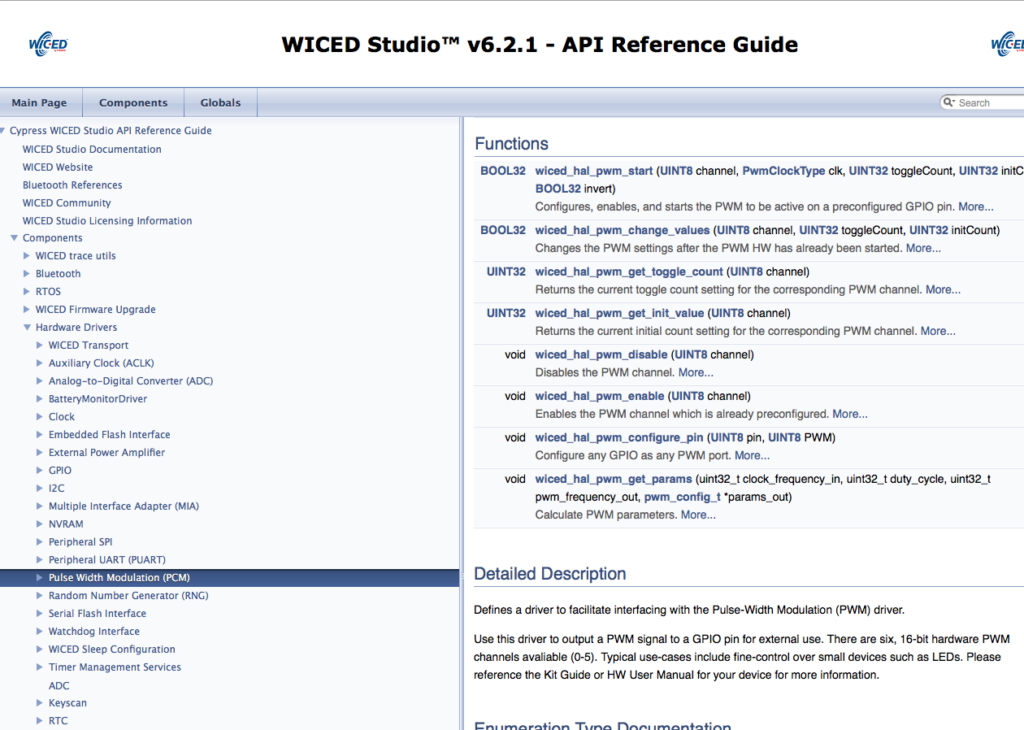
Documentation
All of the hardware blocks on the chip have a set of API functions to help you interface with them. You can find all of that in the Documentation
No comment yet, add your voice below!