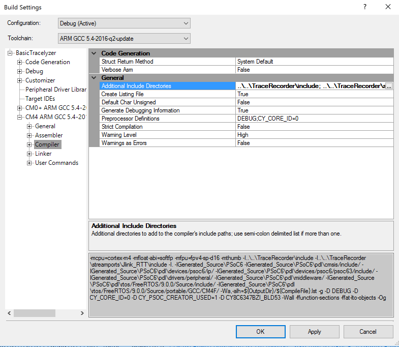
Leica A60S –> Leica S9I Microscope

Summary –

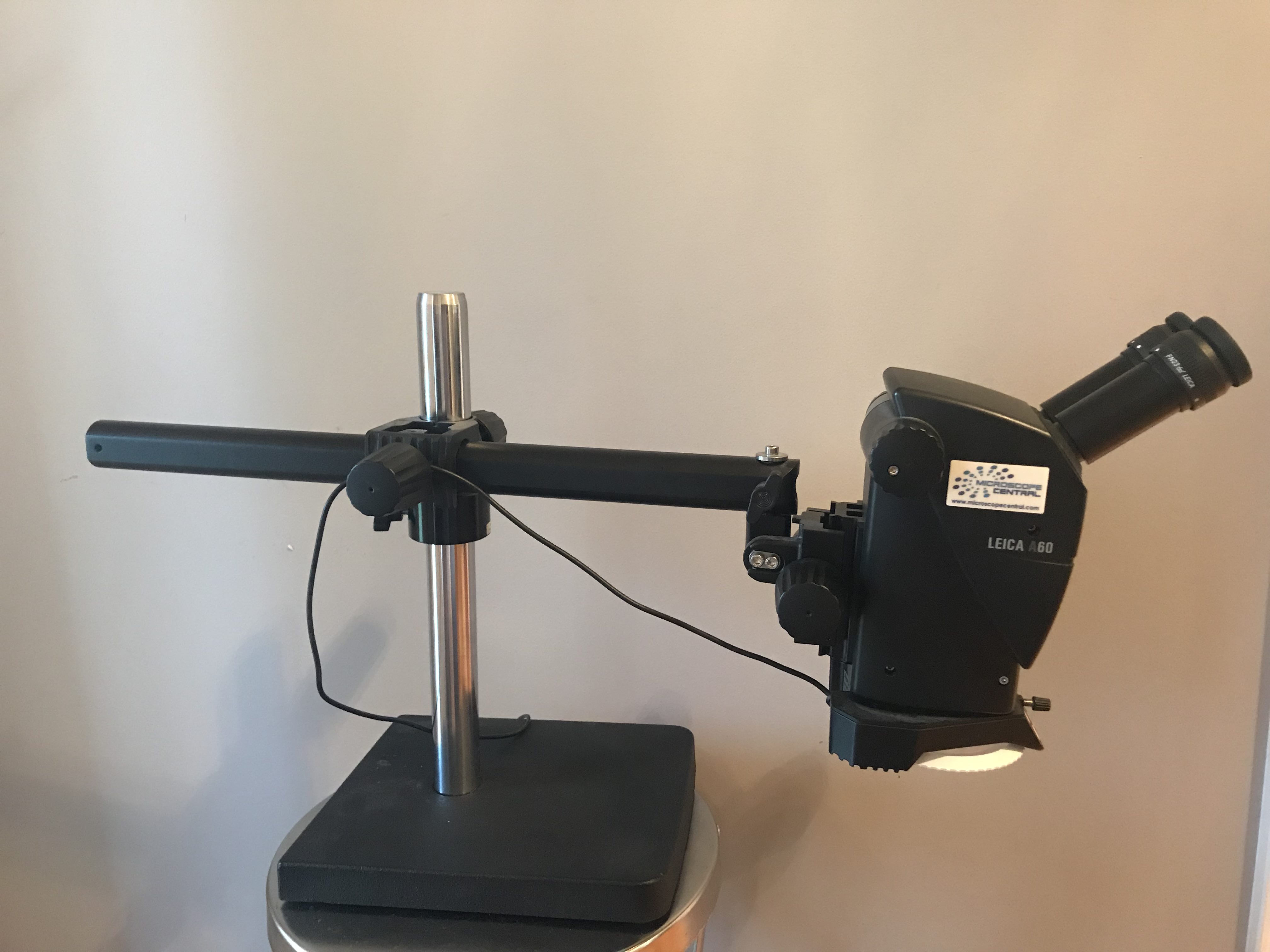
The article is the story of my new Leica S9I microscope.  A few years ago I bought a Leica A60 microscope from Microscope Central.  This was truly a game changing event in my engineering life, particularly the soldering part of my life.  It is a remarkable instrument… and it is amazing how much better you can see while using it.  If you have been following my articles, I am sure that you have seen it in the background of some of the pictures.  The only thing that I really really wished that it had was a camera.  It turns out that Leica never intended for it to have a camera, and in fact there is no good way to attach one.

Leica A60S

A couple of week ago, I started talking with a friend who is getting into electronics about it.  As I talked about the features etc, I started really wishing that I had a camera.  So I did a little bit of research and realized that Microscope Central had developed a camera attachment for the A60.  But after I talked with them about it, I didn’t really feel like it was a good solution for me as it attached over the eye pieces.  But it turns out that since I bought the Leica A60S, Leica had developed a new instrument called the Leica S9I (I stands for integrated camera).

Unboxing the Leica S9I

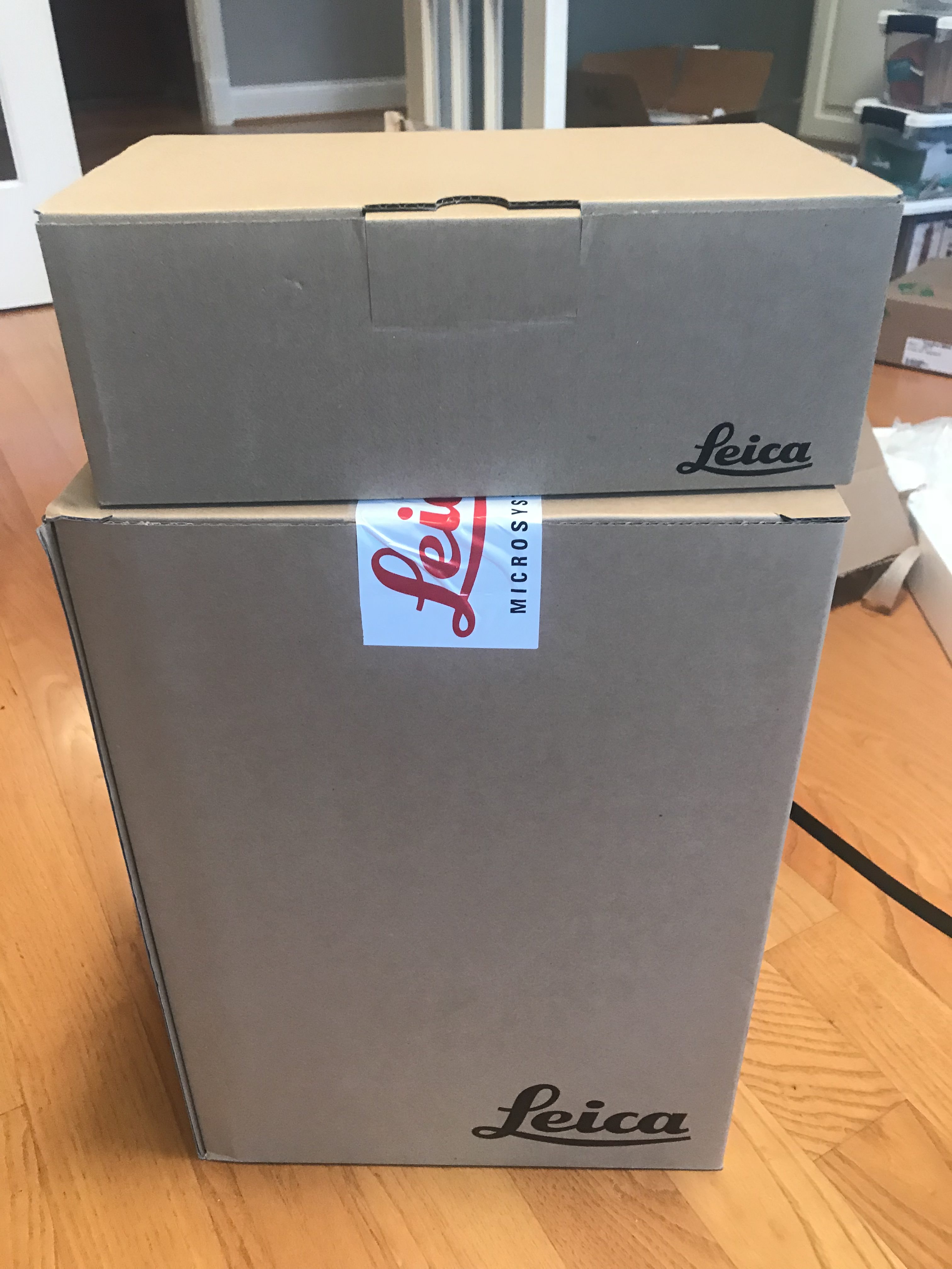
I couldn’t take not having a camera on my A60S, so I pulled the trigger and bought a Leica S9I.  And lookey here what I got from the nice UPS man yesterday.  I love that Leica Logo.

Leica S9I Box

The first thing was to put my Lab assistant Nicholas on the job.  Here he is working on the base.

Leica S9I Stand

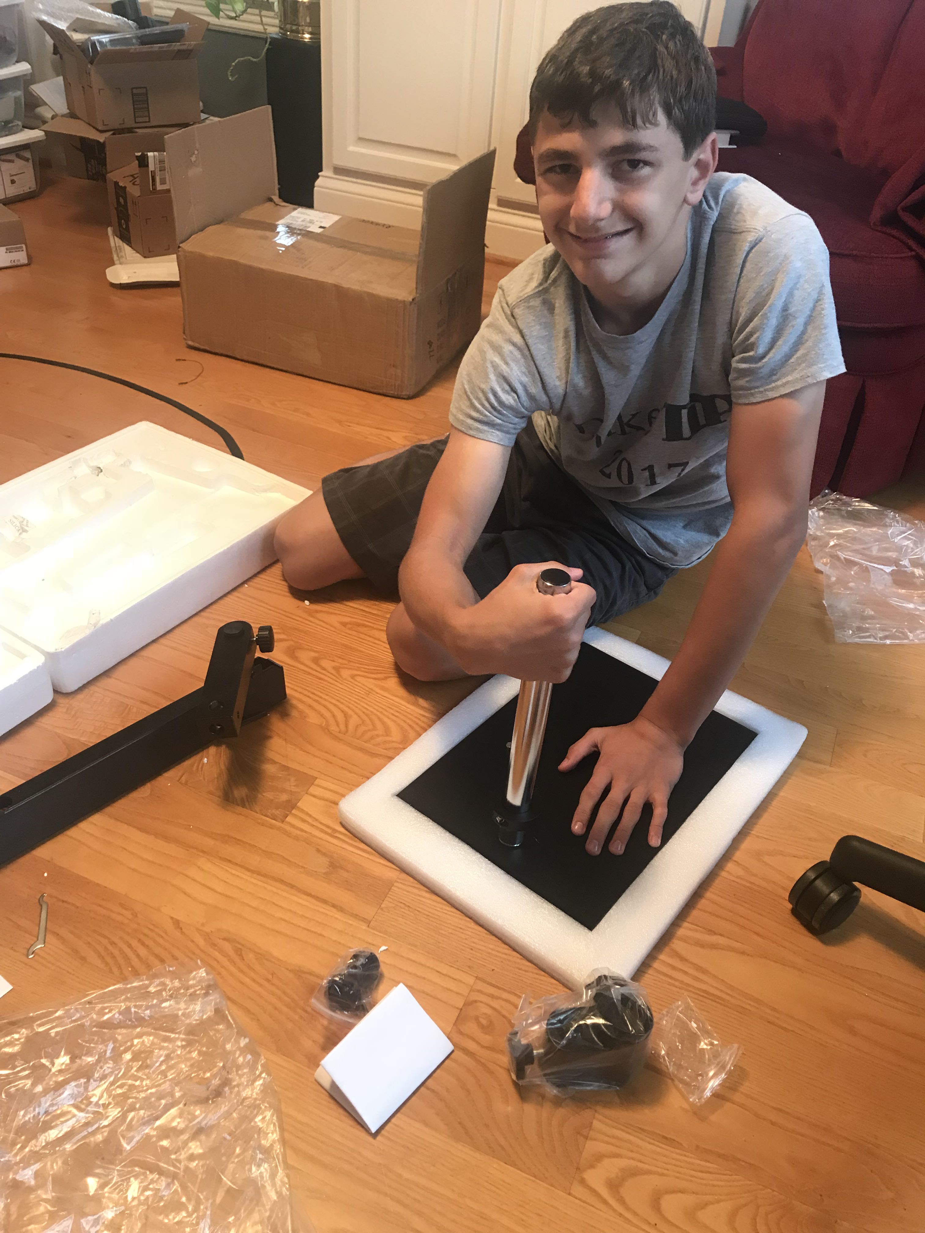
Next, my lab assistant assembles the new telescoping mount – a nice feature that lets me swing the arm and raise and lower the microscope.

Leica S9I Swing Arm

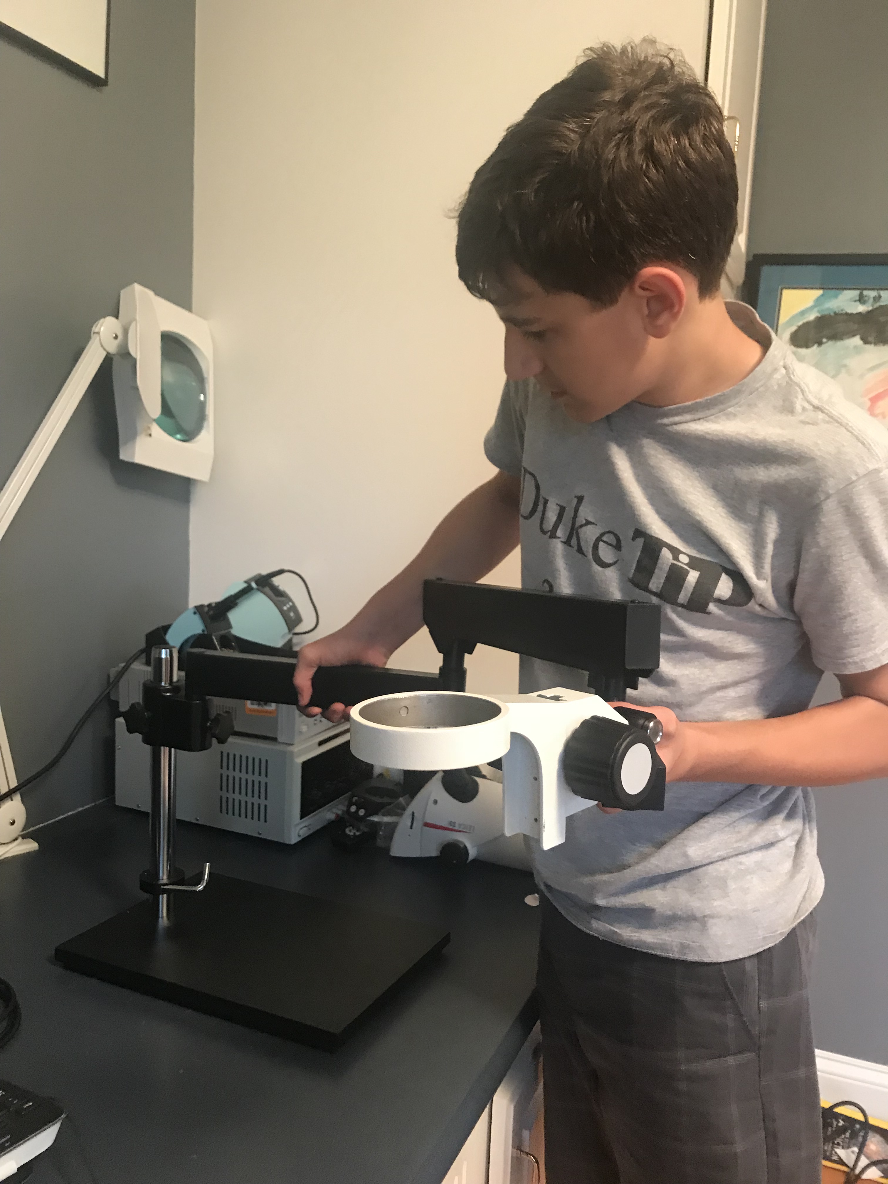
After he got the base built he started on the Leica S9I microscope itself.

Unboxing the Leica S9I

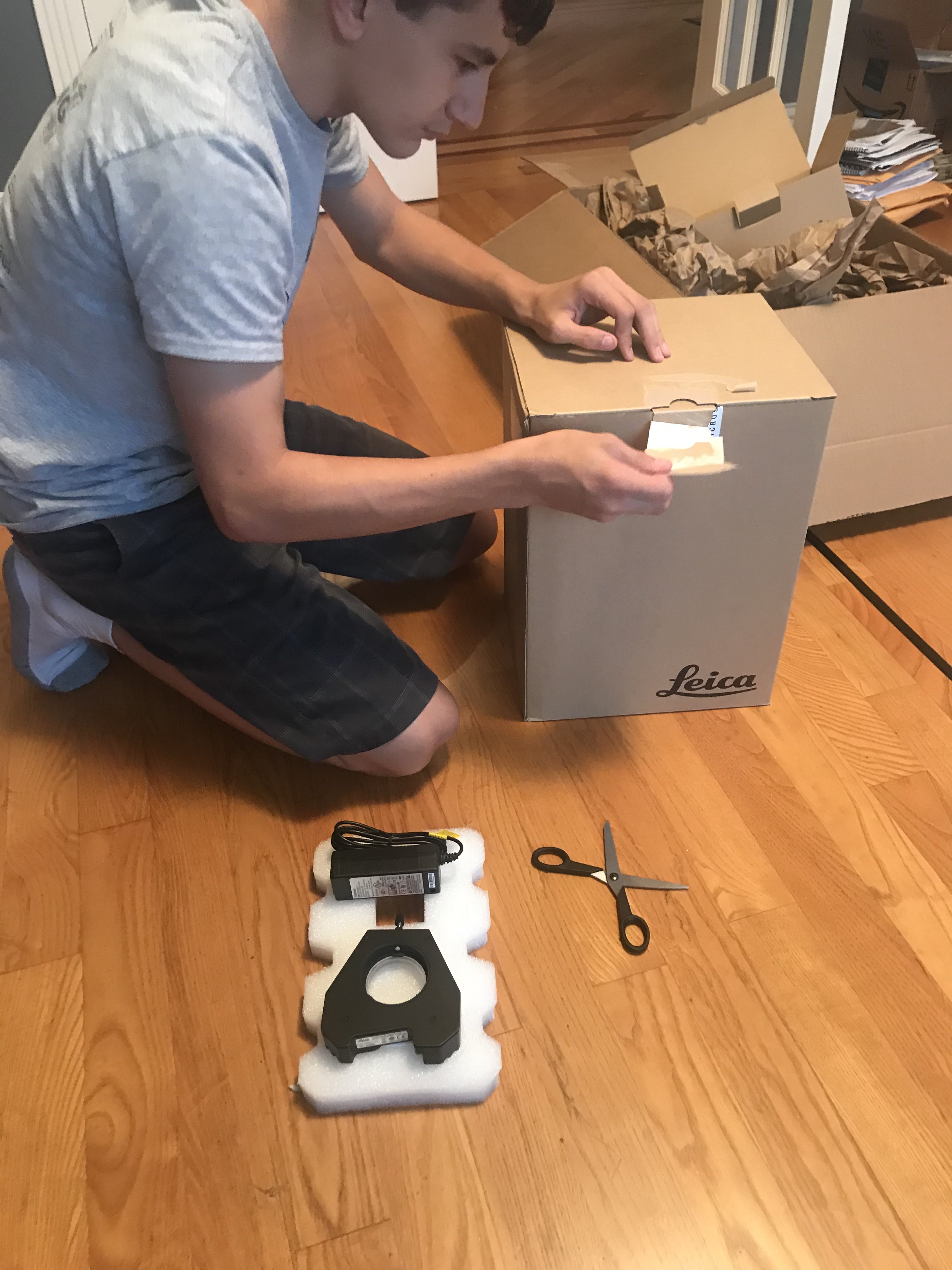
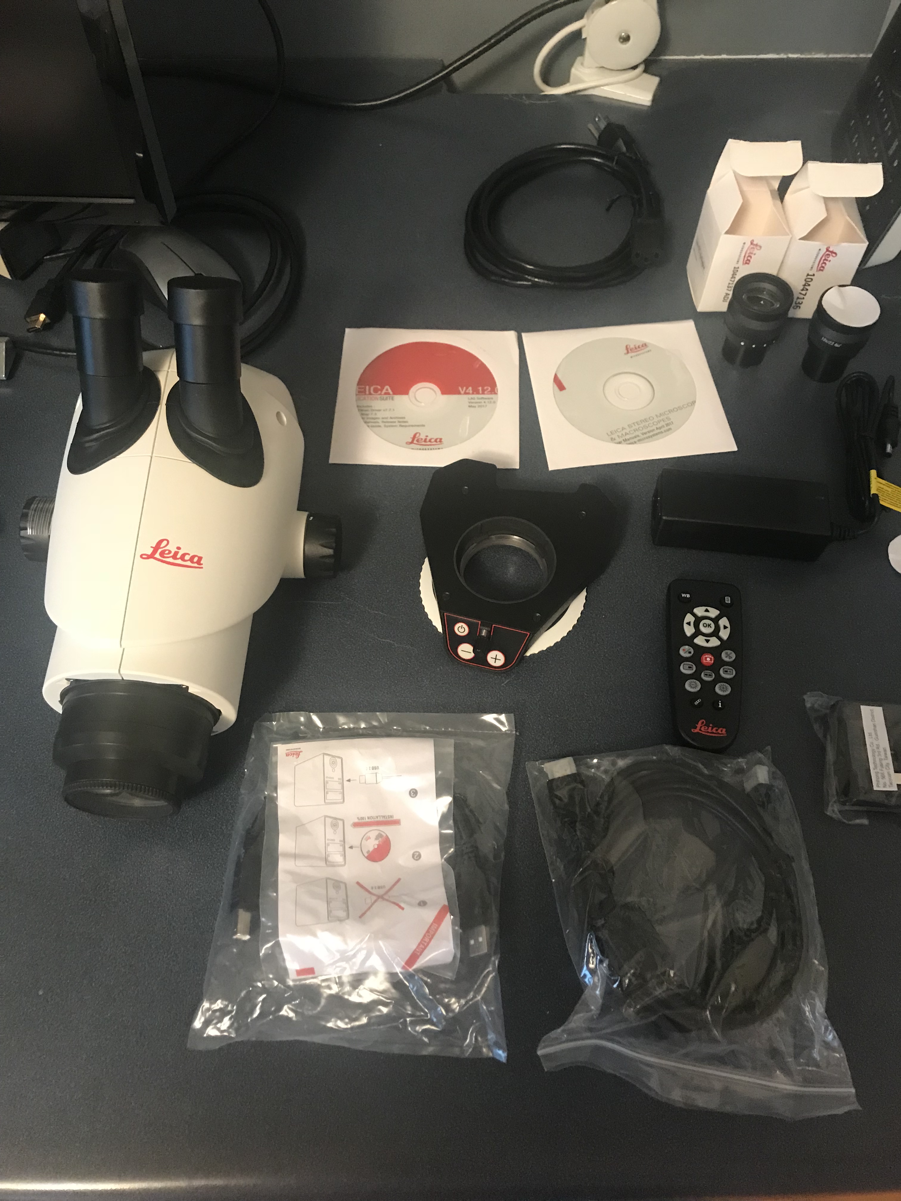
Here is the stuff that came in the box.

  1. The Leica S9I microscope
  2. Two eye pieces (one fixed and one focusing)
  3. A remote control for the integrated Camera
  4. A bad ass LED light
  5. USB and HDMI cables.
  6. Power supply

Leica S9I Parts

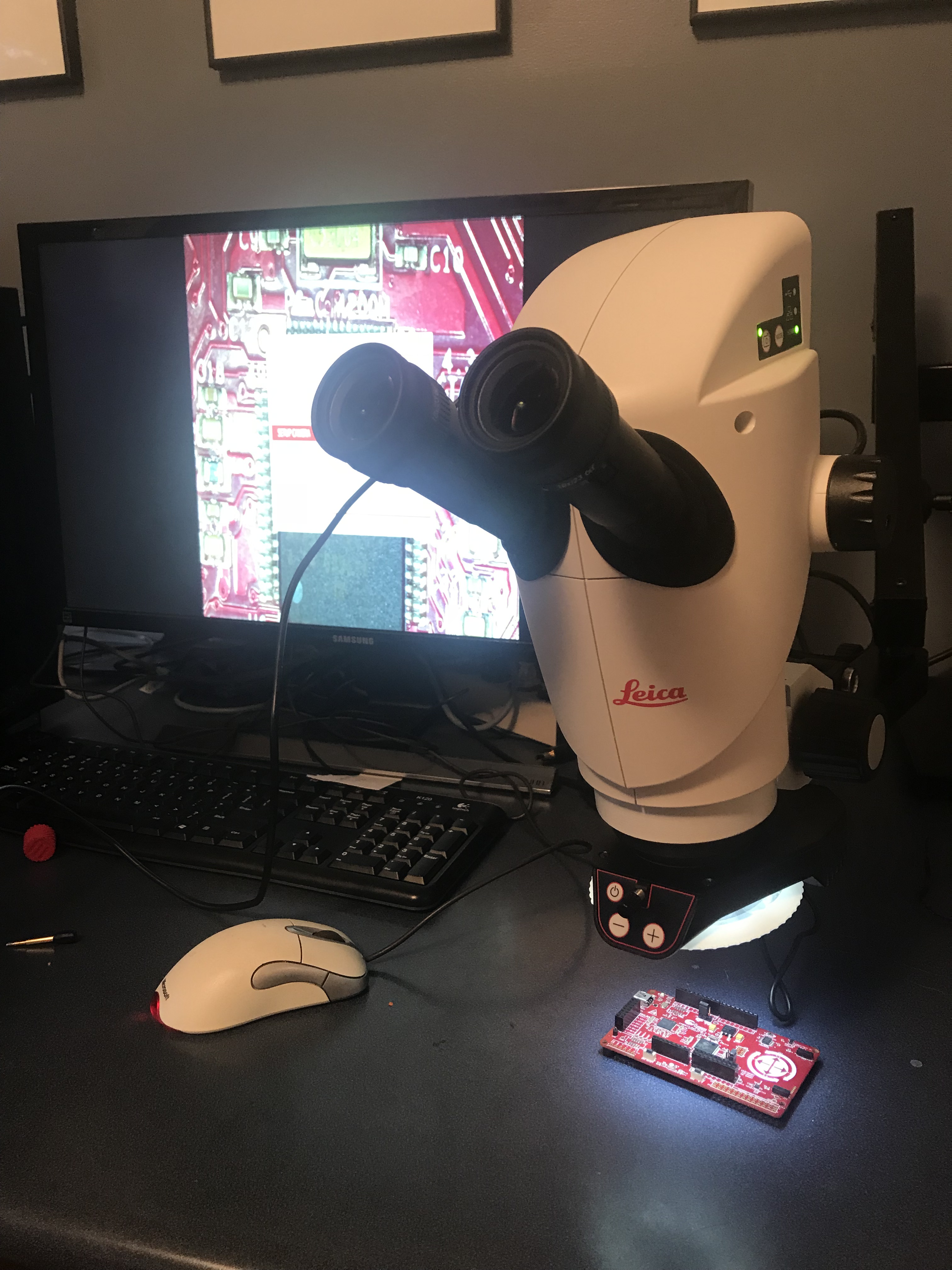
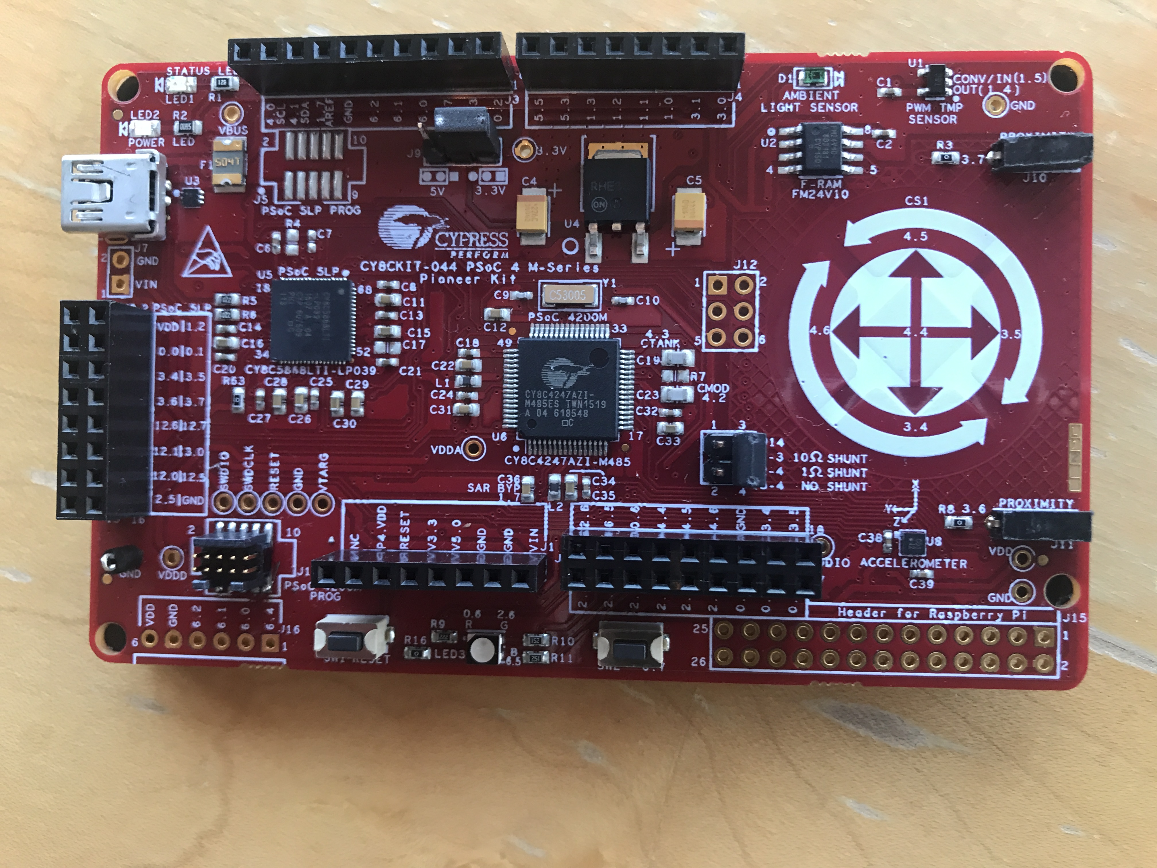
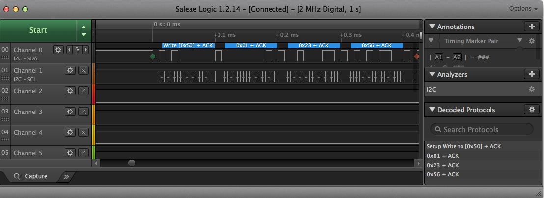
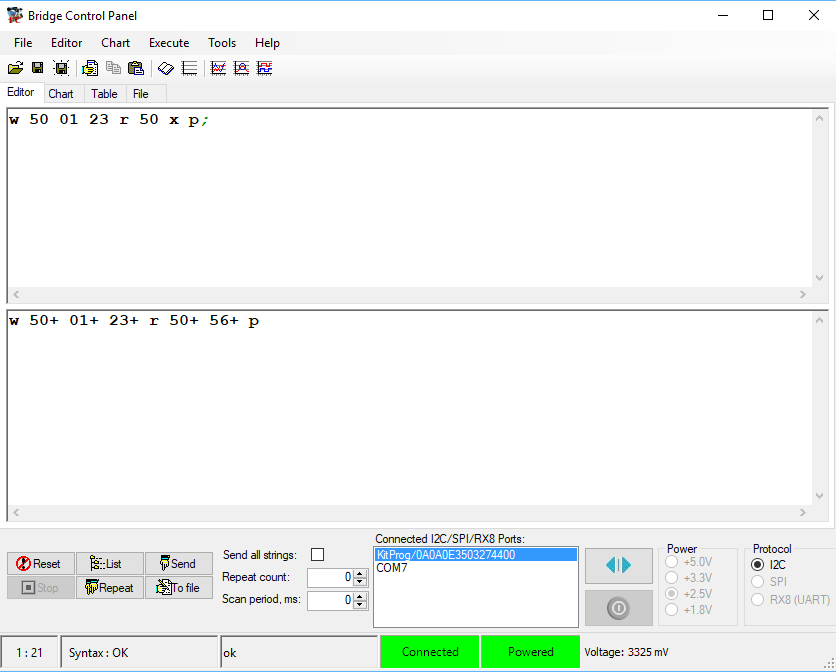
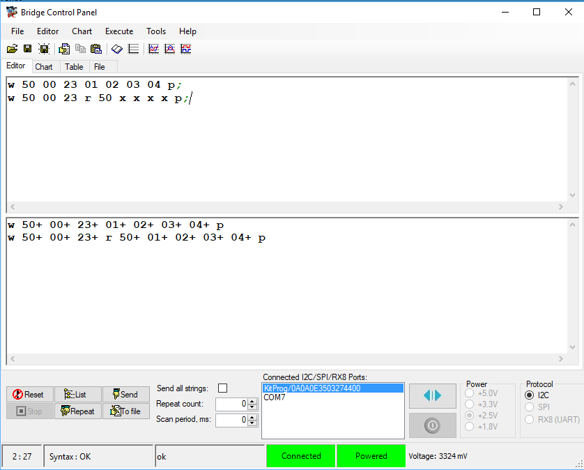
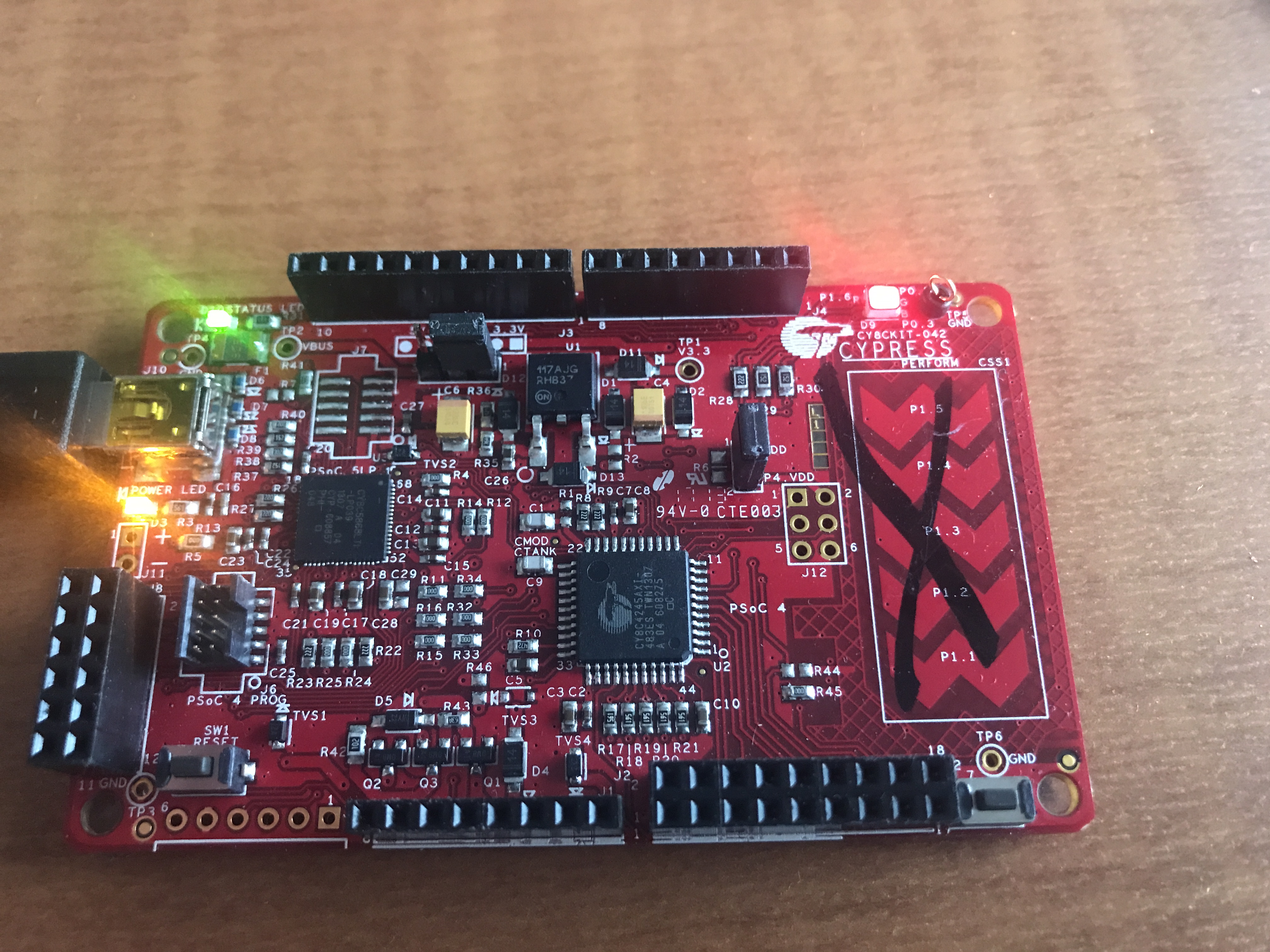
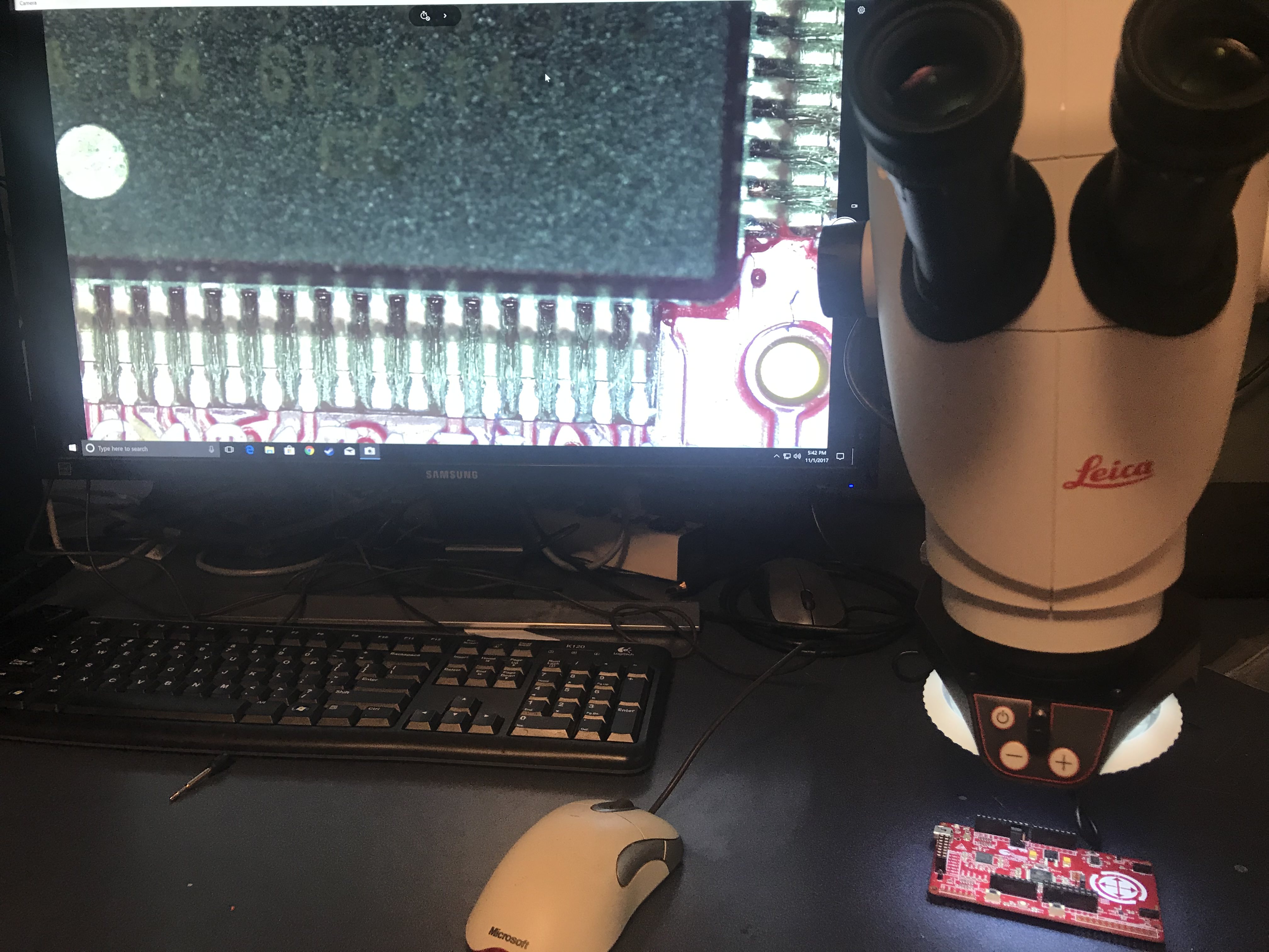
After we (we=Nicholas) got it built he plugged the HDMI cable into the monitor on my desk and took a picture of the setup with the CY8CKIT-044.

Leica S9I First Screen Image

The back of the camera has

  1. HDMI (to attach to a monitor)
  2. SD (sd flash card)
  3. USB (to a computer)
  4. Ethernet

Leica S9I Back

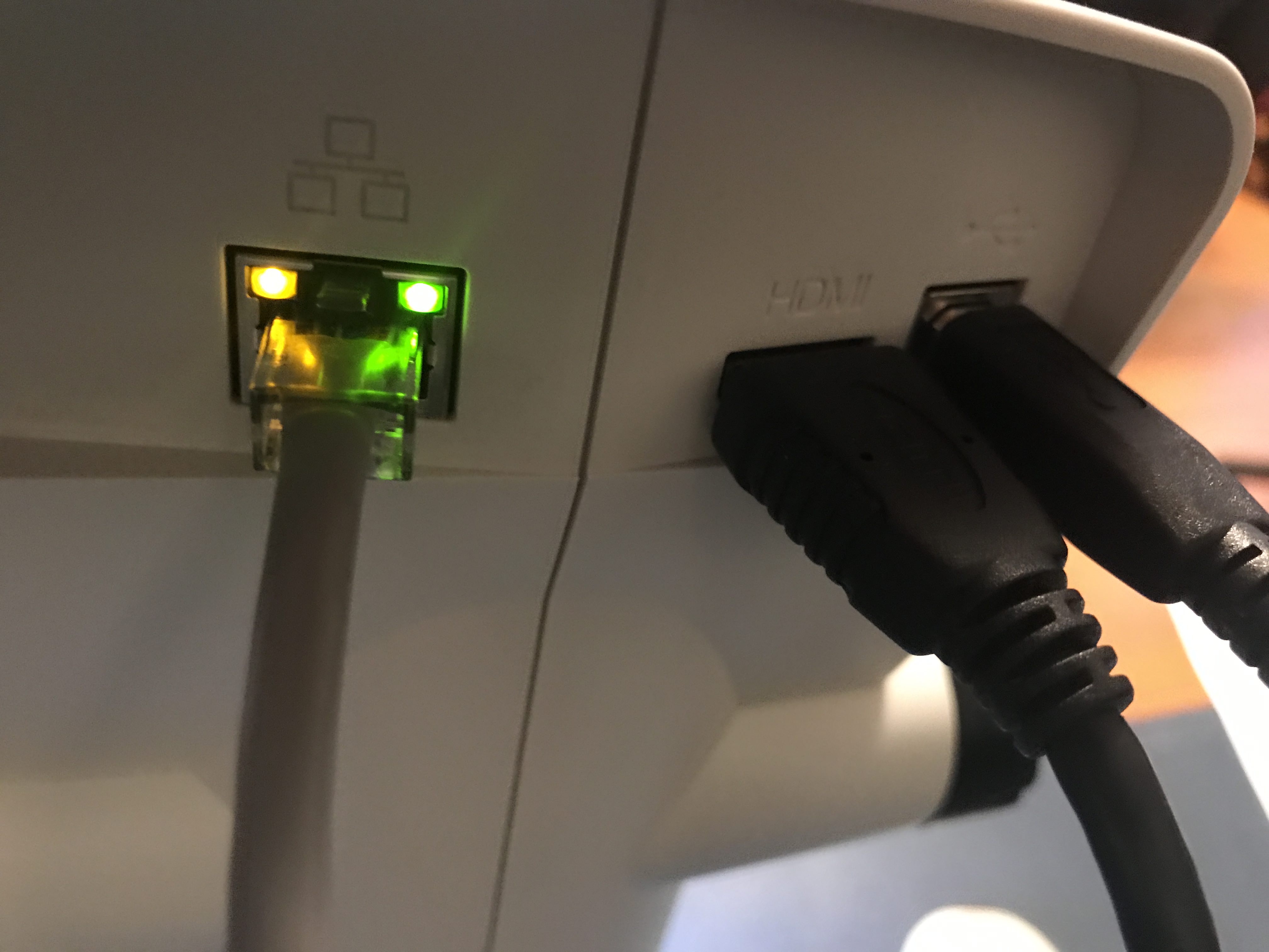
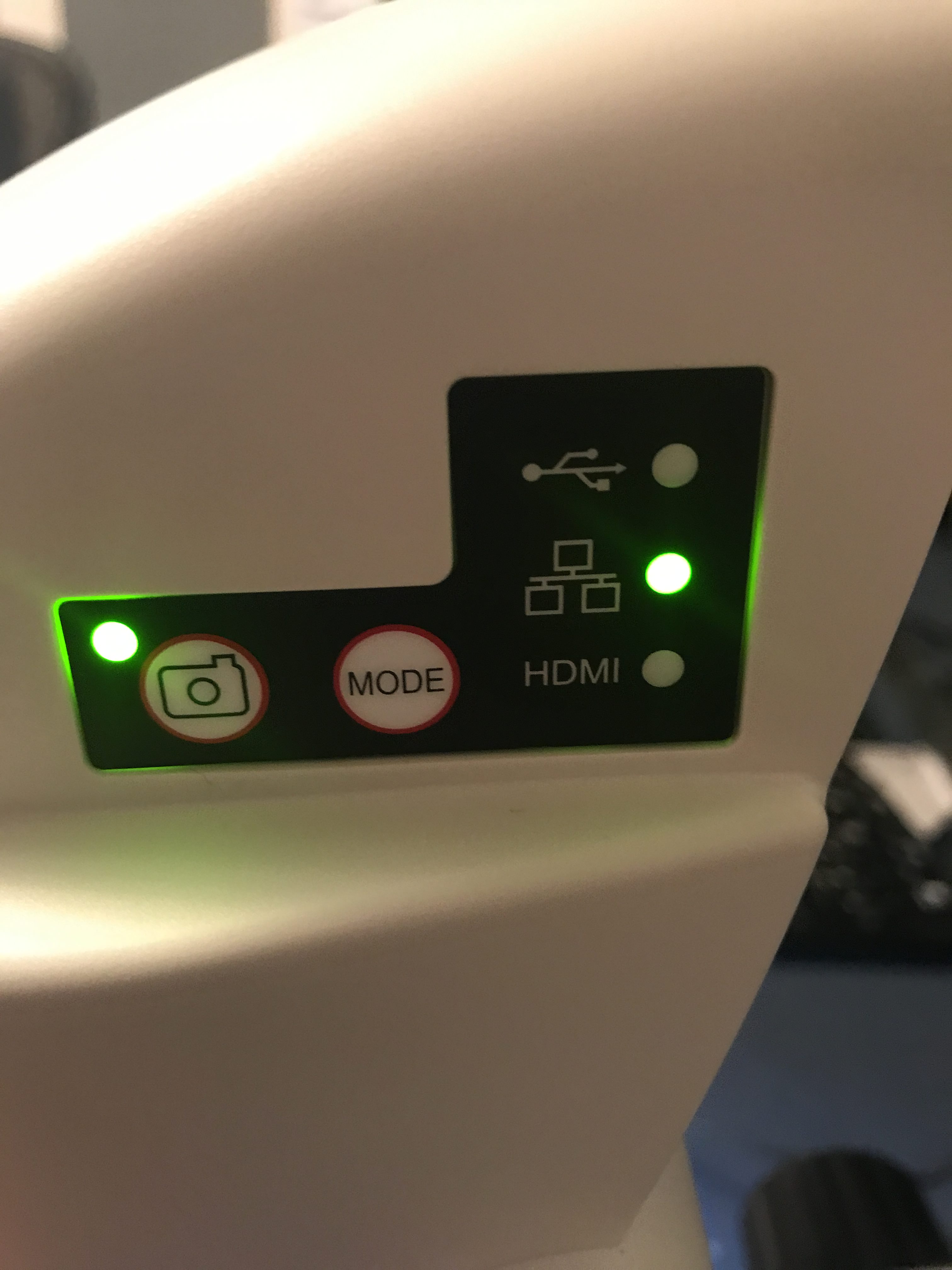
The side of the camera has

  1. A power LED (red means booting, green means on)
  2. Three mode LEDs which show which output is active (Ethernet, USB or HDMI)
  3. A mode button (to switch between Ethernet, USB and HDMI)
  4. A take picture button
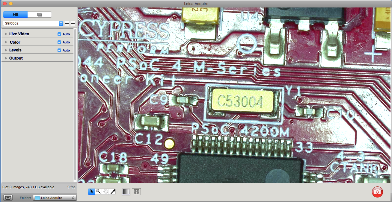
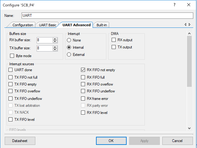
Leica S9I Side

Leica S9I Software

If you plug in Ethernet then you can control the camera with:

  1. A Mac OS Application called Leica Acquire
  2. An iOS Application called Leica Airlab
  3. A PC Application called Leica Application Suite

Here are a couple of screenshots of the Leica Acquire Application.  There is really not much going on with the application.  Basically you can adjust the camera settings and capture video and images.  That being said, I am not sure what else you might want to do.
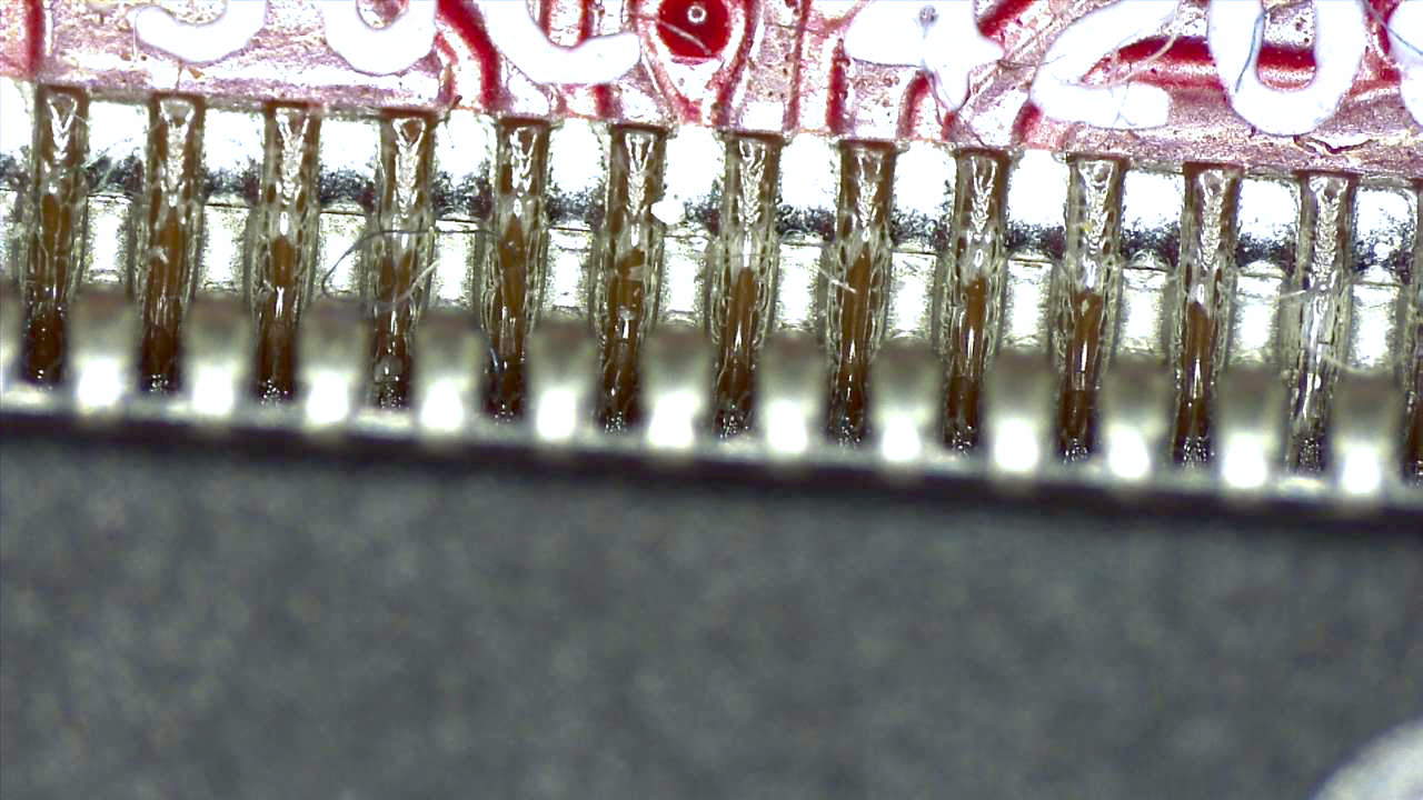
Leica S9I and Leica Acquire

And zoomed in:

Leica S9I and Leica Acquire

And here is the shot when I clicked the camera button (not a screenshot but an acquired image)

Leica S9I and Leica Acquire

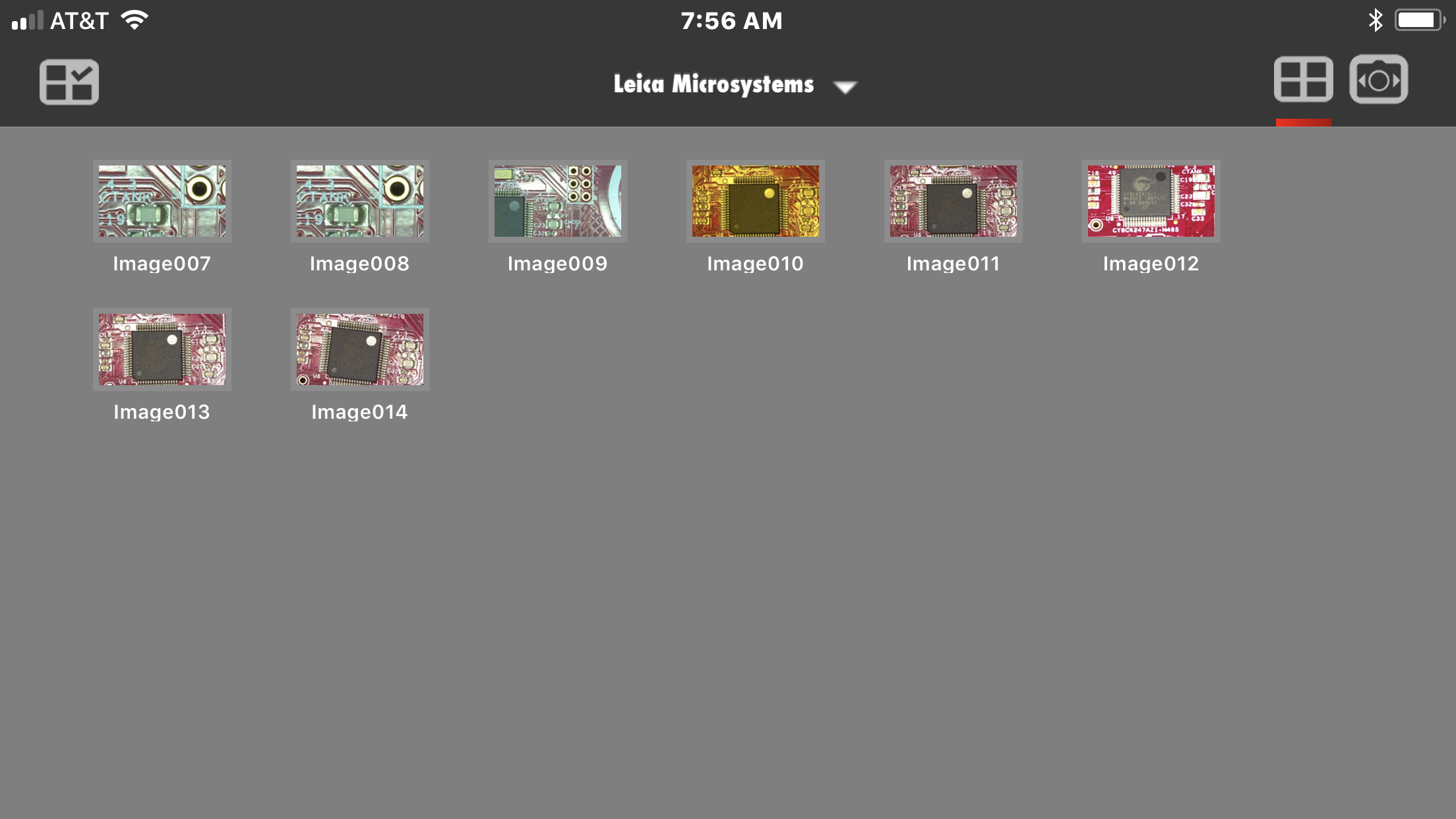
Here are two screenshots of the iOS App.  The first is of the image library in the App.

iOS Leica Airlab

This one is screenshot of the “live” view.  One thing that I am not in love with is the icons on the top of the screen are a bit awkward to use.  But once I got the hang of them it was OK.

iOS Leica Airlab

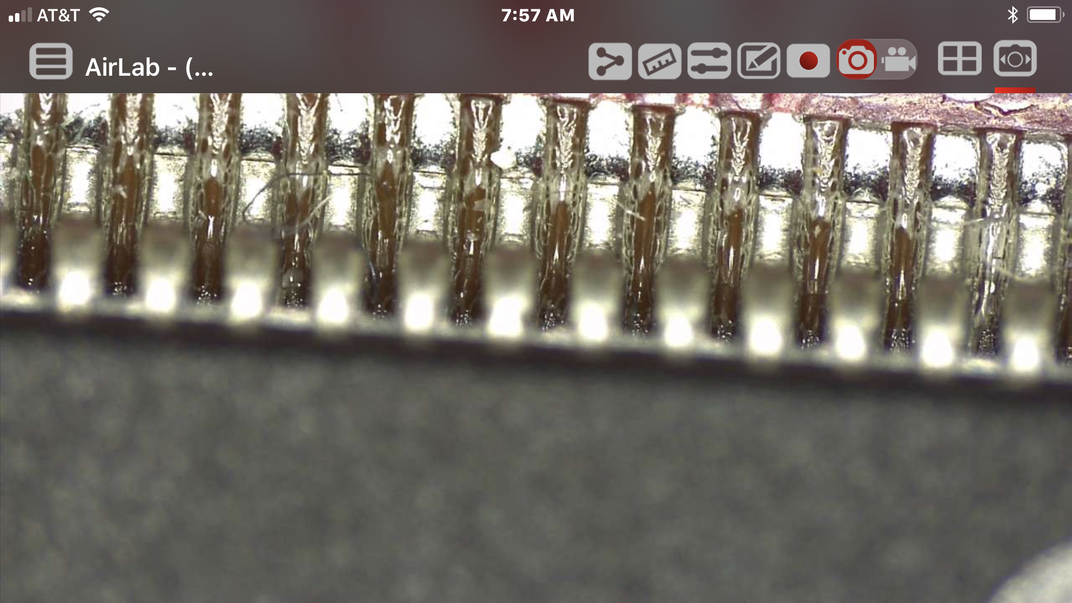
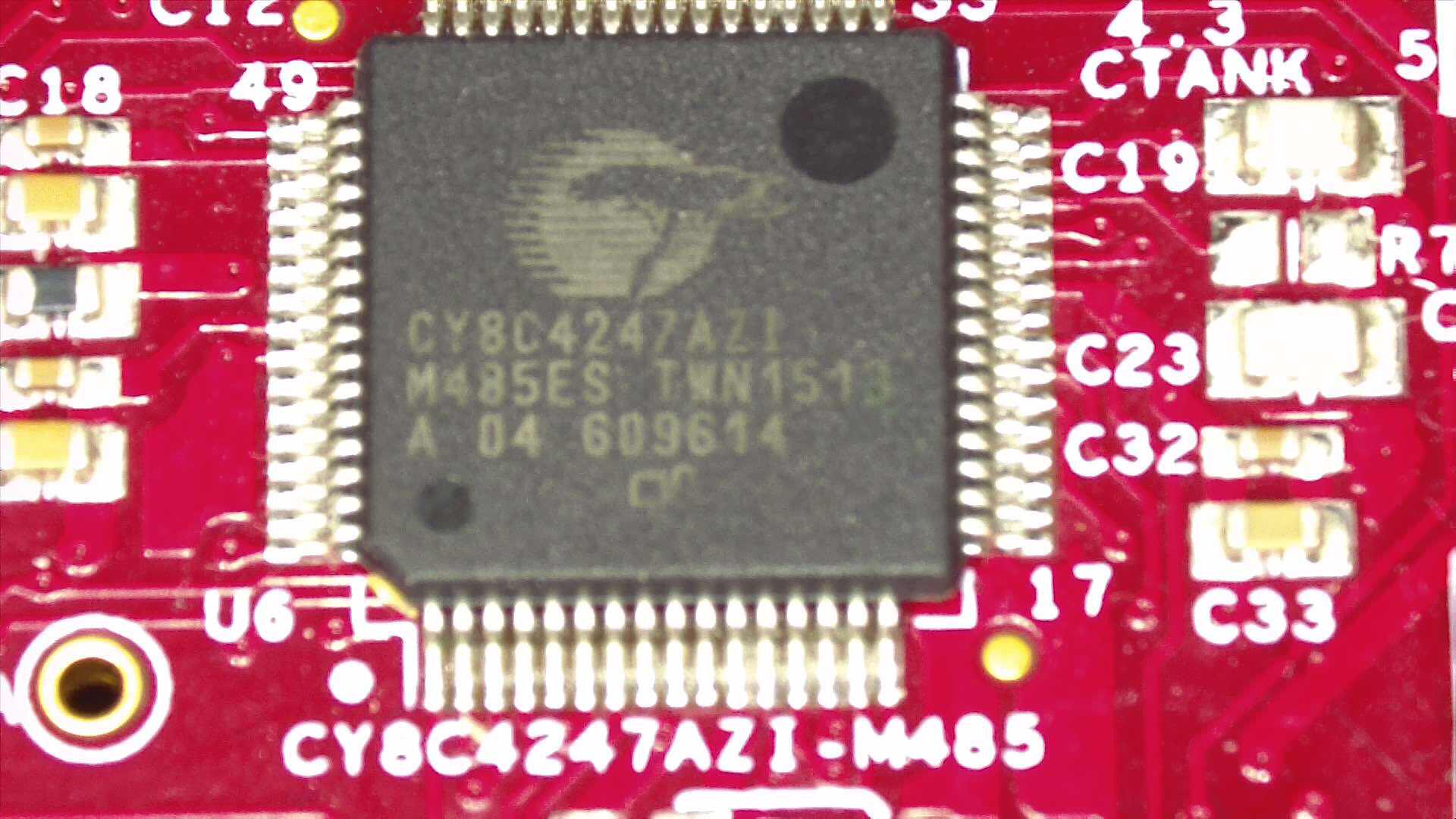
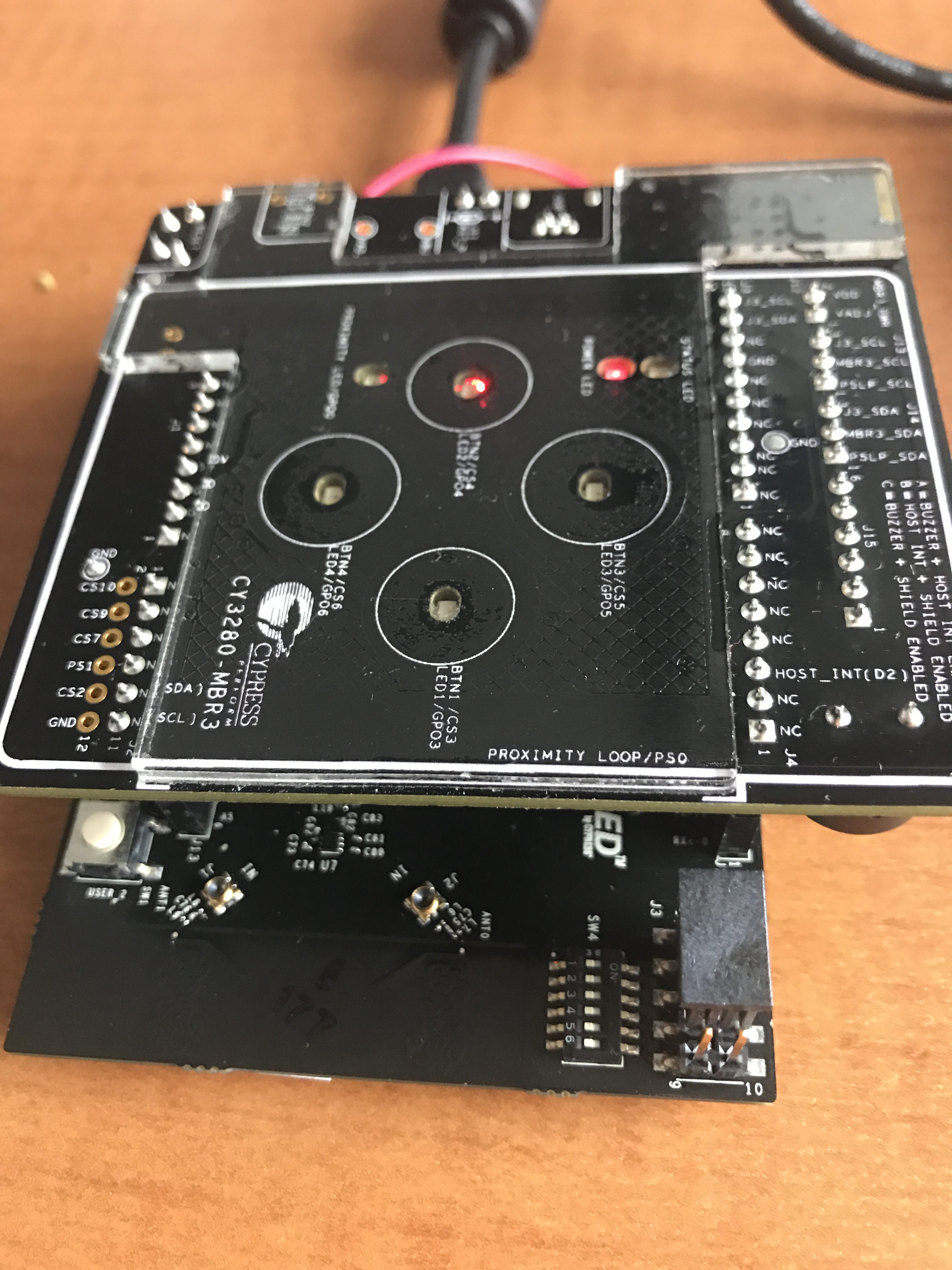
Here is a picture that I took in the iOS App of zoomed in section of the CY8CKIT-044

CY8CKIT-044

Here is are two pictures that I took with the iOS App.  The first is with the Development Kit flat on my desk, and the 2nd with the Development Kit tilted so you can read the laser mark on the CY8C4247AZI-M485.

PSoC 4200M PSoC 4200M

It took a little bit of time to get my eyeballs and the camera settings in sync.  Which was a bit annoying as the only thing that I can say that I don’t like about the Leica S9I is the stupid IR remote control for the camera sucks. The sucky remote control makes it a pain in the neck to get the camera menus configured.  I think that it is too bad that they didn’t put a Cypress Bluetooth device into the camera so that the system would work better.

All that being said.  Leica has always been the leader in optics, and based on my experience with this microscope, that leadership will continue far into the future.  One of the great things about this (and the A60) microscope is the Leica Fusion Optics.  The Leica engineers used an optical trick that is possible because the microscope is binocular.  We all remember from physics class that numerical aperture and magnification are intertwined to set resolution and depth of field.  Moreover, there is a tradeoff between numerical aperture and depth of field.  For soldering you want to have a super sharp image, and a big depth of field.  What Leica Fusion Optics does is present your eyes with two different images.  One that is super sharp, but with limited depth of field.  And the other that is less sharp but with more depth of field.  Then your brain magically combines them into one image that appear to have a giant amount of sharp depth of field.  You can read more about it on the Leica Microscope website.

Microscope Central

My final note in this whole thing is about Microscope Central.  Both times I looked for Microscopes I ended up buying from them.  This is a family owned business in Pennsylvania which made the transition to online at some point.  The first time I clicked on the little “online chat” button at the bottom of the screen it was a holiday Saturday and one of the Miller family answered … and was amazingly helpful in getting me on the right track for buying the A60S.  This morning I thought I would click there, and Scott Miller was there almost immediately.

This time they were awesome in helping me get switched to the Leica S9I.  They spent a bunch of time talking me through optics issues on the industrial microscopes.  Moreover he helped me spend money on things that matter.. e.g. Leica glass… but also helped my buy a much less expensive stand, which is very good as well.  All in all I find this remarkable because I am hardly a relevant customer, yet the treated me well.  I wouldn’t hesitate to buy from them again.

CY8CKIT-044 PSoC4200M Real Time Clock

Summary

In my article entitled “FreeRTOS FAT SL – Musing on my Implementation“, I lamented that I was supposed to implement a Real Time Clock so that the reads and writes of files could be timestamped, but didnt.  I knew that the PSoC4200M Real Time Clock is actually really easy to use.  But, I didn’t because I didn’t want to fix the command line interface that I was using.  In this article I will show you how to implement a PSoC4200M Real Time Clock in FreeRTOS.  Then in the next article Ill show you how to implement the FreeRTOS Command Line Interface to set the time and turn on the FreeRTOS FAT SL Clock Driver.

PSoC4200M Real Time Clock Schematic

The first thing to do is copy the FreeRTOS Template project.  Then add the UART and RTC components to the project schematic from the PSoC Creator Component Catalog.

PSoC4200M Real Time Clock Schematic

The PSoC4200M Real Time Clock will have the default settings for the component.

PSoC4200M Real Time Clock Configuration

To make an accurate clock, I want to turn on the Watch Crystal Oscillator which drives the Watch Dog Timers.  To do this, click on the “Clocks” tab of the Design Wide Resources.  Then press edit clock.

PSoC4200M Real Time Clock Configuration DWR

Once you are on the clock editor page, turn on the WCO (by pressing the checkmark in the upper left hand corner).  Then turn on the WDT Timer 0 in the Periodic Timer Mode.  Set the divider to 32768 so that the RTC will get 1 interrupt per second.  You also need to select the source of the RTC to be Timer 0.

PSoC4200M Real Time Clock Low Frequency Clock Configuration

Firmware

In the firmware I create a new task called “uartTask” which just starts the RTC, then prints out the time when the user presses ‘t’.  Obviously I didnt set the clock, so it starts from 12:00:00.  Ill fix that in the next post after I get the FreeRTOS Command Line Interpreter working.

void uartTask(void *arg)
{
    (void)arg;
    UART_Start();
    clearScreen();
    UART_UartPutString("Start Real Time Clock Demo\n");
    UART_SetCustomInterruptHandler(uartISR);
    uint32 timeBCD;
    char buff[32];
    
    RTC_Start();

    
    while(1)
    {
        ulTaskNotifyTake(pdTRUE,portMAX_DELAY);
        
        while(UART_SpiUartGetRxBufferSize()) // if there is data then read and process
        {
            char c;
            
            c= UART_UartGetChar();
			switch(c)
			{
                case 't':
                    
                    timeBCD = RTC_GetTime();
                    sprintf(buff,"%d:%d:%d\n",(int)RTC_GetHours(timeBCD),(int)RTC_GetMinutes(timeBCD),(int)RTC_GetSecond(timeBCD));
                    UART_UartPutString(buff);
                    
                break;

You can find this project called RTC-Example in the workspace PSoC-Filesystem on the IoT Expert GitHub site or git@github.com:iotexpert/PSoC-FileSystem.git

FreeRTOS FAT SL – F_FS_THREAD_AWARE

Summary

If you have been following this series of articles about the FreeRTOS FAT SL filesystem, you might have read my post called “FreeRTOS FAT SL – Musings on my Implementation”.  In that post I asked myself “Why do I get the error message ‘undefined reference to xQueueCreateMutex'”.  Here is a screen shot from PSoC Creator

FreeRTOS FAT SL Error Message

When I traced through the problem I noticed that it comes from this block of code:

#if F_FS_THREAD_AWARE == 1
	{
		extern SemaphoreHandle_t fs_lock_semaphore;

		if( fs_lock_semaphore == NULL )
		{
			fs_lock_semaphore = xSemaphoreCreateMutex();
            
			if( fs_lock_semaphore == NULL )
			{
				return F_ERR_OS;
			}
		}
	}
#endif /* F_FS_THREAD_AWARE */

Which gave me the hint that it had something to do with F_FS_THREAD_AWARE being turned on.  When I got the error message I assumed that it had something to do with the tangled mess of include files that I had created.  This flag is set in config_fat_sl.h

/**************************************************************************
**
**  FAT SL user settings
**
**************************************************************************/
#define F_SECTOR_SIZE           512  /* Disk sector size. */
#define F_FS_THREAD_AWARE       1     /* Set to one if the file system will be access from more than one task. */
#define F_MAXPATH               16    /* Maximum length a file name (including its full path) can be. */
#define F_MAX_LOCK_WAIT_TICKS   20

So, to “solve” the problem I just turned it off, knowing that I would need to come back to it to figure out because for sure if you are using the FreeRTOS FAT SL filesystem in an RTOS, which I am, you had better have the thread awareness turned on.  Specifically what the flag does is create and use a mutex around the actual “disk” to prevent re-entrant code from hosing you.

This morning I sat down and figured it out.  The answer is that I am an idiot.  Almost all of the features of FreeRTOS that you might want to use need to be turned on in the FreeRTOSConfig.h file.  This is true of mutex.  Here is the section of the file with the issue… look at line 19

#define configUSE_PREEMPTION                    1
#define configUSE_PORT_OPTIMISED_TASK_SELECTION 0
#define configUSE_TICKLESS_IDLE                 0
#define configCPU_CLOCK_HZ                      ( ( unsigned long ) CYDEV_BCLK__SYSCLK__HZ )
#define configTICK_RATE_HZ                      1000
#define configMAX_PRIORITIES                    5
#define configMINIMAL_STACK_SIZE                128
#define configMAX_TASK_NAME_LEN                 16
#define configUSE_16_BIT_TICKS                  0
#define configIDLE_SHOULD_YIELD                 1
#define configUSE_TASK_NOTIFICATIONS            1
#define configUSE_MUTEXES                       0 // <=== here is the problem line
#define configUSE_RECURSIVE_MUTEXES             0
#define configUSE_COUNTING_SEMAPHORES           0
#define configUSE_ALTERNATIVE_API               0 /* Deprecated! */
#define configQUEUE_REGISTRY_SIZE               10
#define configUSE_QUEUE_SETS                    0
#define configUSE_TIME_SLICING                  0
#define configUSE_NEWLIB_REENTRANT              0
#define configENABLE_BACKWARD_COMPATIBILITY     0
#define configNUM_THREAD_LOCAL_STORAGE_POINTERS 5

When I turn on the configUSE_MUTEXS things compile just fine and I can get on with my life.

FreeRTOS FAT SL – Musings on my Implementation

Summary

I just finished writing the “last” article about building a FreeRTOS FAT SL filesystem into the Cypress FM24V10 FRAM using a CY8CKIT-044.  My implementation works pretty well…. but I am not really that happy with it.  As I sit here and write this article I am not totally sure what I should do next.

I suppose the first thing to do is talk about the things that I don’t like in what I did.

  1. Real Time Clock
  2. Command Line Interpreter
  3. DMA Media Driver
  4. Include files
  5. F_FS_THREAD_AWARE 0
  6. Template project
  7. Performance Metrics
  8. Wear Leveling
  9. Performance Metrics
  10. Discussion of FAT Filesystems

Real Time Clock

As part of the port, you are supposed to provide psp_rtc.c which has one function, psp_getcurrentimedate.  This function is used to get the time to use as a timestamp on files.  I left it default, which means every transaction is timestamped the same, probably not good.  Moreover, there is an RTC in the PSoC4200M that is on the CY8CKIT-044.  The board also has the watch crystal which drives the RTC populated so there is really no good reason not to turn it on.

FreeRTOS FAT SL PSoC RTC

However, when I wrote the original example the command line interpreter that I build only took one character at a time, so there was no good way to set the clock.   Which brings me to the next problem.

Command Line Interpreter (CLI)

When I originally build the example project my command interpreter just had an infinite loop that waited for a character from the keyboard, then did one command based on that character.  It looks like this:

   while(1)
    {
        ulTaskNotifyTake(pdTRUE,portMAX_DELAY);
        
        while(UART_SpiUartGetRxBufferSize()) // if there is data then read and process
        {
            char c;
            
            c= UART_UartGetChar();
			switch(c)
			{
				case 'i': 
				break;
				
			
                case '?': // Print out the list of commands
                    
                break;
                    
                default:
                break;
			}
        }
        // Turn the interrupts back on
        UART_ClearRxInterruptSource(UART_INTR_RX_NOT_EMPTY); 
        UART_SetRxInterruptMode(UART_INTR_RX_NOT_EMPTY);
    }

What I did was cheap and easy… but, FreeRTOS has a CLI built in, so I suppose that I should have used.

DMA Media Driver

When I read and write from the FRAM I put in code that is blocking.  Meaning that it essentially hangs the entire system until they return.  Not really good given that this is an RTOS.  This is what all of the I2C_ functions below do.

  status = I2C_I2CMasterSendStart( calcI2CAddress(sector),I2C_I2C_WRITE_XFER_MODE);
    if(status != I2C_I2C_MSTR_NO_ERROR)
    {
        UART_UartPutString("I2C Error\n");
        return MDRIVER_RAM_ERR_SECTOR;
    }
    int i;
    I2C_I2CMasterWriteByte((address>>8)&0xFF);
    I2C_I2CMasterWriteByte(address & 0xFF); //

There is no reason that I shouldn’t have used the DMA engine to read and write the FRAM which would have freed up the processor.

Include files

I absolutely hate the scheme that I used to name and use the includes in the FreeRTOS FAT SL port.  I should fix this for sure.

F_FS_THREAD_AWARE 0

When I originally tried to compile this project I marked this #define from “config_fat_sl.h” as “1”.  However when I do that, I end up with this error which I should for sure fix as the code is not reentrant and this #define protects you.

An RTOS bug in the FreeRTOS FAT SL Implementation

Template project

My good friend Mark Saunders pointed out PSoC Creator has a new feature which you can use to make template projects.. which I didnt know about until he told me.  Obviously this would be better than what I am doing.

Performance Metrics

I did not collect any performance metrics when I build this project.  How much RAM? Flash?  How long does it take to read and write files?  I don’t know.  Moreover, I put in debugging information into the media driver which was counter productive to good memory usage.  For instance in this snip from the readsector function I define a big ass buffer of 128 bytes on line 134, then I printout a message to the uart each time this function is called.

static int fram_readsector ( F_DRIVER * driver, void * data, unsigned long sector )
{
    char buff[128]; // A scratch buffer for UART Printing
    (void)driver;
    uint16 address;
    uint32_t status;
    
    sprintf(buff,"Read sector %d\n",(int)sector);
    UART_UartPutString(buff);

Error Checking

There are a bunch of places where I could have put in much better error checking, and I didnt.  For instance in this section of the readsector function if the I2C_I2CMasterWriteByte function fails, it probably hangs the I2C bus until the chip is reset… this is bad.  Even when an error occurs, printing a message probably isn’t a good idea (line 146).

    if(status != I2C_I2C_MSTR_NO_ERROR)
    {
        UART_UartPutString("I2C Error\n");
        return MDRIVER_RAM_ERR_SECTOR;
    }
    int i;
    I2C_I2CMasterWriteByte((address>>8)&0xFF);
    I2C_I2CMasterWriteByte(address & 0xFF); // 
    
    
    I2C_I2CMasterSendRestart(calcI2CAddress(sector),I2C_I2C_READ_XFER_MODE);

Wear Leveling

Many nonvolatile memory chip will wear out if you write them too many time.  Even 100K cycles can easily happen on a key sector of the filesystem for instance sector 0.  One convient thing about the FRAM is that it doesnt wear out.  But, when I started this journey I was originally going to use the PSoC6 development kit which uses a NOR Flash.  The NOR Flash will for sure wear out.  To combat this problem, people have developed wear leveling schemes.  But I don’t address this issue at all with my media driver.

Discussion of FAT Filesystems

As I wrote about the FreeRTOS FAT SL Filesystem I was originally planning a tutorial on file systems.  But as I dug a little bit a whole bunch of issues came up which felt a little bit overwhelming to address.  The issues that were left unaddressed are:

  1. Copywrite of the FAT File System
  2. Efficiency of FAT File Systems
  3. The licensing of the FreeRTOS FAT SL
  4. Other FAT implementations

I suppose that at some point I should come back and look at those issues.

FreeRTOS FAT SL – PSoC Example Project (Part 2)

Summary – Examples using FreeRTOS FAT SL

In the previous several articles I have written about the FreeRTOS FAT SL Filesystem.  This included using the Cypress FM24V10 FRAM, creating an FRAM media driver and building an example project.  This article will show you the C-functions in “extestfs.c” that are used to actually test the filesystem.  Notice that I named all of the functions starting with “ex” which I adopted from the FreeRTOS FAT SL examples.  The functions in this article are all called by the command line interpreter that I built in the previous post.  They include

  • exInit – Initializing the Filesystem
  • exCreateFile – Creating a file in the FileSystem
  • exReadFile – Reading the data from a file
  • exFormat – Formatting the disk
  • exDriveInfo – Printing the drive information
  • exDirectory – Print an “ls” or “dir”

exInit

Before the FreeRTOS FAT SL Filesystem can do anything, you must initialize it.  All this function does is call the function that I created to turn on the file system in the media port.  One thing that is interesting is that it returns an error code that tells you if the file system is formatted or  not.   It figured this out by looking at the data in the first sector of the FRAM.

// This function initalize the filesystem
void exInit(void)
{
    unsigned char ucStatus;
    
	/* First create the volume. */
	ucStatus = f_initvolume( fram_initfunc );
    UART_UartPutString("Initialized sucessfully\n");
	/* It is expected that the volume is not formatted. */
	if( ucStatus == F_ERR_NOTFORMATTED )
	{
        UART_UartPutString("Filesystem Unformatted\n");
	}
    
    else
    {
        UART_UartPutString("Filesystem Formatted\n");
    }
}

exCreateFile

This functiom creates a file called “afile.txt” in the FreeRTOS FAT SL filesystem with the ASCII characters for 0-9.  I did something that was probably not helpful in that I made a loop (on line 43) that started a ‘0’ which is also known as 49 (go look at the ASCII table).

This function calls f_open which will create a new file when it is passed the argument “w”.  I also use the function f_putc to output characters to the file.

As I am looking at the code to write this article I realized that I didnt f_close the file (which I have now fixed).

#define FILENAME "afile.txt"
// exCreateFile - this function creates a file called "afile.txt" an
void exCreateFile(void)
{
    F_FILE *pxFile;
    UART_UartPutString("Attempting Create & Write File\n");
    pxFile = f_open(FILENAME, "w" );
  
    if(pxFile)
    {
        for(int i='0' ; i< '9' ; i++)
        {
            f_putc(i,pxFile);
        }
        f_close(pxFile);
    }
    else
    {
        UART_UartPutString("Failed File Create\n");
    }
}

exReadFile

The exReadFile functions reads all of the characters out of the “afile.txt” and prints them to the screen.  It uses the function f_getc which reads one character from the file.  Notice that I open the file in read mode by using the “r” option.

void exReadFile(void)
{
    UART_UartPutString("Attempting Read\n");
    F_FILE *pxFile;
    pxFile = f_open( FILENAME, "r" );
    if(pxFile)
    {
        while(!f_eof(pxFile))
        {
            UART_UartPutChar(f_getc(pxFile));
        }
        f_close(pxFile);
    }
    else
    {
        UART_UartPutString("File not found\n");
    }
}

exFormat

The exFormat function calles f_format with the FAT12 option.  It is impossible to use FAT16 and FAT32 which require a much larger media to use.  FAT12 was originally created for use on smallish floppy disk.

void exFormat(void)
{
    char buff[128];
	/* Format the created volume. */
    unsigned char ucStatus;
	ucStatus = f_format( F_FAT12_MEDIA );
	if( ucStatus == F_NO_ERROR )
	{
        UART_UartPutString("Formatted sucessfully\n");
    }
    else
    {
        sprintf(buff,"Error = %d\n",ucStatus);
        UART_UartPutString(buff);   
        UART_UartPutString("Format Error\n");
    }   
}

exDriveInfo

The exDriveInfo function calls the f_getfreespace function to find out how much space is free for use on the FRAM FreeRTOS FAT SL Filesystem.

void exDriveInfo( void )
{
    char buff[128];
    F_SPACE xSpace;
    unsigned char ucReturned;

    /* Get space information on current embedded FAT file system drive. */
    ucReturned = f_getfreespace( &xSpace );
    if( ucReturned == F_NO_ERROR )
    {
        /* xSpace.total holds the total drive size, xSpace.free holds the
        free space on the drive, xSpace.used holds the size of the used space
        on the drive, xSpace.bad holds the size of unusable space on the
        drive. */
        sprintf(buff,"Free Space = %lu\nUsed Space = %lu\nTotal = %lu\n",xSpace.free,xSpace.used,xSpace.total);
        UART_UartPutString(buff);
    }
    else
    {
        /* xSpace could not be completed.  ucReturned holds the error code. */
        UART_UartPutString("Free space failed\n");
    }
}

exDirectory

The exDirectory function calls the f_findfirst and f_findnext functions to iterate all of the files and directories on the top level of the file system.  The f_findfirst function uses a wildcard regular expression to match filenames. When it finds a file it prints information about that file.

void exDirectory( void )
{
    char buff[128];
    F_FIND xFindStruct;

    /* Print out information on every file in the subdirectory "subdir". */
    if( f_findfirst( "*.*", &xFindStruct ) == F_NO_ERROR )
    {
        do
        {
            sprintf(buff,"filename:%s ", xFindStruct.filename );
            UART_UartPutString(buff);

            if( ( xFindStruct.attr & F_ATTR_DIR ) != 0 )
            {
                UART_UartPutString ( "is a directory directory\n" );
            }
            else
            {
                sprintf ( buff, "is a file of size %lu\n", xFindStruct.filesize );
                UART_UartPutString(buff);
            }

        } while( f_findnext( &xFindStruct ) == F_NO_ERROR );
    }
}


FreeRTOS FAT SL – PSoC Example Project (Part 1)

Summary

In the previous articles I discussed using the FRAM, and making a FreeRTOS FAT SL media driver.  In this article I will discuss building an example project that uses that work to make a real FreeRTOS FAT SL system example.  I was originally planning on making just one article explaining the example, but my example code turned out to be a little bit sprawling, so I decided to break it into two pieces.  In part 1 (this article) I will

  1. Build the FreeRTOS Template
  2. Import the FreeRTOS FAT SL FileSystem & FRAM Media Driver
  3. Build a command line interpreter
  4. Nuke the data in the FRAM

In the next article I will show you the details of using the FreeRTOS FAT SL filesystem.

Build the FreeRTOS Template & Schematic

I start the project from my FreeRTOS template project.  You can read all about that here.  Then I add in the components required to make things work.  The schematic is simple:

  • A UART component to run the Command Line Interpreter
  • An I2C to control the FRAM

FreeRTOS FAT SL Example Schematic

The I2C is setup as a master at it highest speed setting.

FreeRTOS FAT SL I2C Configuration

On the CY8CKIT-044 the pins need to be configured as so:

FreeRTOS FAT SL - Pin Configuration

Import the FreeRTOS FAT SL FileSystem & FRAM Media Driver

The first step in importing the FreeRTOS FAT SL FileSystem and and media driver is to copy the FreeRTOS-Plus-FAT-SL directory into my project.  Once that is done, my folder structure looks like this:

FreeRTOS FAT SL Code Layout

The next step is to fix the include paths to include the config, api and psp include directories.  This can be done on the build settings menu.

FreeRTOS FAT SL Include Files

Finally I import the .h and .c files into my project so that it looks like this:

FreeRTOS FAT SL Project Directory Structure

Build a Command Line Interpreter (CLI)

I think that it is convenient to have a command line utility (one that connects to the UART port) to send commands to my program to test it.  To build the CLI, I create a task called uartTask which takes keys from the terminal and then processes them in a giant switch statement.  While I was building the FreeRTOS FAT SL system, I noticed that FreeRTOS also has a scheme for CLIs which I will try out in the future.

In the UART configuration I turn on the “RX FIFO not empty” interrupt (meaning that there is data in the fifo that needs to be processed)

FreeRTOS FAT SL UART Configuration

I connect the interrupt to the interrupt service routine on line 64.  In the ISR I use the FreeRTOS notification scheme to send notifications to the uartTask to wakeup and process data (line 50).

My CLI has two different things that it does:

  • It calls functions in the file extestfs.c that start with “ex” , meaning example, to format, initalize etc.
  • It keeps a “currentSector” variable that lets me print out the raw data in a sector.  The currentSector variable is incremented (with the keyboard +) and decremented (with the keyboard -) and set to 0 with the (keyboard 0)

Once all of the keys have been processed (the Rx FIFO buffer is empty – line 71), it turns back on the Rx FIFO interrupt (lines 150-151), then waits for another notification from the ISR (line 69)

TaskHandle_t uartTaskHandle;
void uartISR()
{
    
    BaseType_t xHigherPriorityTaskWoken;
    // disable the interrupt
    UART_SetRxInterruptMode(0);
    vTaskNotifyGiveFromISR(uartTaskHandle,&xHigherPriorityTaskWoken);
    portYIELD_FROM_ISR( xHigherPriorityTaskWoken );
    
}

// This is the main task which processes commands from the UART and prints the results
// on the screen.
void uartTask(void *arg)
{
    (void)arg;
    UART_Start();
    I2C_Start();
    clearScreen();
    UART_UartPutString("Start Filesystem Demo\n");
    UART_SetCustomInterruptHandler(uartISR);
    
    int currentSector=0;    
    while(1)
    {
        ulTaskNotifyTake(pdTRUE,portMAX_DELAY);
        
        while(UART_SpiUartGetRxBufferSize()) // if there is data then read and process
        {
            char c;
            
            c= UART_UartGetChar();
			switch(c)
			{
				case 'i': // Initialize the RTOS
					exInit();
				break;
				case 'f': // Format the FRAM
					exFormat();
				break;
                    
				case 'q': // Return the drive information
					exDriveInfo();
				break;
			
                case 'w': // Create a file
				    exCreateFile();
				break;
					
				case 'r': // Read the file that was created (if it exists)
				    exReadFile();
				break;
					
				case '0': // Goto to sector 0 and print the data
				    currentSector = 0;
					exPrintSector(0,0,0);
				break;
				
			    case '+': // Print the "current" sector and go to the next
				    exPrintSector(0,0,currentSector);
				    currentSector += 1;
			    break;
					
			    case '-': // print the current sector and go to the previous
				    exPrintSector(0,0,currentSector);
				    currentSector -= 1;
				    if(currentSector<0)
					    currentSector =0;
			    break;
                    
    			case 'd': // Do a directory
	    			exDirectory();
		    	break;
                    
                case 'c':
                    clearScreen();
                break;
                    
                case 'b': // Erase the FRAM (write all 0's)
                    blankFRAM();
                break;
			
                case '?': // Print out the list of commands
                    UART_UartPutString("b - Blank FRAM - write all 0's\n");
                    UART_UartPutString("i - Initalize Filesystem\n");
                    UART_UartPutString("f - Format FRAM\n");
                    UART_UartPutString("q - Print FileSystem Information\n");
                    UART_UartPutString("w - Create a file called \"afile.bin\"\n");
                    UART_UartPutString("r - Read the file called \"afile.bin\" and print contents\n");
                    UART_UartPutString("0 - Goto sector 0 and print contents\n");
                    UART_UartPutString("+ - Goto next sector and print contents\n");
                    UART_UartPutString("- - Goto previous sector and print contents\n");
                    UART_UartPutString("d - Print Directory\n");
                    UART_UartPutString("c - Clear Screen\n");
                    UART_UartPutString("? - Print help\n");        
                    
                break;
                    
			    default:
				    UART_UartPutString("Unknown :");
				    UART_UartPutChar(c);
				    UART_UartPutChar('\n');
			    break;
			}
        }
        // Turn the interrupts back on
        UART_ClearRxInterruptSource(UART_INTR_RX_NOT_EMPTY); 
        UART_SetRxInterruptMode(UART_INTR_RX_NOT_EMPTY);
    }
}

Nuke the FRAM Data

I thought that it would be a good idea to have a function to put 0’s in all of the locations in the FRAM, to prove that I could start with a clean slate.  This function does just that.  Specifically it write 0’s to the 64K locations in I2C address 0x50 (the first bank) and to I2C address 0x51 (the second bank)

// This function erases - write 0's into the FRAM... also known as NUKE the FRAM
void blankFRAM(void)
{
    int i;
    UART_UartPutString("Starting Erase 1st Block\n");
    I2C_I2CMasterSendStart(0x50,I2C_I2C_WRITE_XFER_MODE);
    I2C_I2CMasterWriteByte(0);
    I2C_I2CMasterWriteByte(0);
    for(i=0;i<0xFFFF;i++) // Write 64K of 0's to erase first bank
    {
        I2C_I2CMasterWriteByte(0);
    }
    I2C_I2CMasterSendStop();
    UART_UartPutString("Starting Erase 2nd Block\n");
    I2C_I2CMasterSendStart(0x51,I2C_I2C_WRITE_XFER_MODE);
    I2C_I2CMasterWriteByte(0);
    I2C_I2CMasterWriteByte(0);
    for(i=0;i<0xFFFF;i++) // write 64k of 0's to erase 2nd bank
    {
        I2C_I2CMasterWriteByte(0);
    }
    I2C_I2CMasterSendStop();
    
    UART_UartPutString("Erase Complete\n");

}

As always you can find this project on the IoT Expert GitHub site git@github.com:iotexpert/PSoC-FileSystem.git

FreeRTOS FAT SL FileSystem Porting to PSoC4M

CY8CKIT-044 for FreeRTOS FAT FL FileSystem

Summary of FreeRTOS FAT SL FileSystem Port

In the previous article I discussed the Cypress 24V10 FRAM which I am going to use to store nonvolatile data for the FreeRTOS FAT SL FileSystem.  The “SL” in the name stands for “super light” and was built by HCC Embedded for, get this, embedded applications.

In this article I am going to show you how to build a media driver to make the FreeRTOS FAT SL FileSystem work.  In the next article I will talk about how to actually use the FreeRTOS FAT SL FileSystem on the CY8CKIT-044 using the Cypress FMV24V10 FRAM.

The media driver is pretty simple,  you just need to provide the following functions:

And two structures

  • F_DRIVER – Function pointers to the media driver functions
  • F_PHY – Information about the FRAM

To make all of this work I will start by copying the “ram” driver that was provided as an example (ill call mine framdrv_f.c).  The file that I started with resides in FreeRTOS-Plus/Source/FreeRTOS-Plus-FAT-SL/media-drv/ram/ramdrv_f.c

F_DRIVER Structure

The F_DRIVER structure mostly contains function pointers to the driver functions (which you create).  All throughout the FreeRTOS FAT SL FileSystem code it will do things like :

status = mdrv->getstatus( mdrv );

which calls the function in the media driver structure named “getstatus”.

Here is the exact definition of the F_DRIVER STRUCTURE (found in FreeRTOS-Plus-FAT-SL/api/api_mdriver.h) :

typedef struct F_DRIVER  F_DRIVER;

typedef int           ( *F_WRITESECTOR )( F_DRIVER * driver, void * data, unsigned long sector );
typedef int           ( *F_READSECTOR )( F_DRIVER * driver, void * data, unsigned long sector );
typedef int           ( *F_GETPHY )( F_DRIVER * driver, F_PHY * phy );
typedef long          ( *F_GETSTATUS )( F_DRIVER * driver );
typedef void          ( *F_RELEASE )( F_DRIVER * driver );

typedef struct F_DRIVER
{
  unsigned long  user_data;     /* user defined data */
  void         * user_ptr;      /* user define pointer */

  /* driver functions */
  F_WRITESECTOR          writesector;
  F_READSECTOR           readsector;
  F_GETPHY               getphy;
  F_GETSTATUS            getstatus;
  F_RELEASE              release;
} _F_DRIVER;

typedef F_DRIVER *( *F_DRIVERINIT )( unsigned long driver_param );

The user_data and user_ptr do not appear to be used anywhere in the FreeRTOS FAT SL FileSystem code, so I am not sure what they had in mind for those variables.

The F_PHY Structure

The other structure that is needed (sort of) is F_PHY.  This structure contains parameters that were originally meant for disk drives and are no longer used.  For the FRAM I will divide up the 128k array into “sectors” of “512” bytes.  For some reason which I don’t understand the sector size must be fixed to 512 bytes.  The history of FAT filesystems is incredibly messy, and I started to dig through it so that I understood the number, but I am not sure that there are enough hours in my life.

typedef struct
{
  unsigned short  number_of_cylinders;
  unsigned short  sector_per_track;
  unsigned short  number_of_heads;
  unsigned long   number_of_sectors;
  unsigned char   media_descriptor;

  unsigned short  bytes_per_sector;
} F_PHY;

As I wrote this article I didnt remember setting up the F_PHY structure… but things still worked (ill address this later in the article).

F_DRVERINIT()

This function sets up the function pointers and marks the in_use variable.

/****************************************************************************
 *
 * fram_initfunc
 *
 * this init function has to be passed for highlevel to initiate the
 * driver functions
 *
 * INPUTS
 *
 * driver_param - driver parameter
 *
 * RETURNS
 *
 * driver structure pointer
 *
 ***************************************************************************/
F_DRIVER * fram_initfunc ( unsigned long driver_param )
{
  ( void ) driver_param;

    UART_UartPutString("Calling init\n");

  if( in_use )
    return NULL;

  (void)psp_memset( &t_driver, 0, sizeof( F_DRIVER ) );

  t_driver.readsector = fram_readsector;
  t_driver.writesector = fram_writesector;
  t_driver.getphy = fram_getphy;
  t_driver.release = fram_release;

  in_use = 1;

  return &t_driver;
} /* fram_initfunc */

F_GETPHY()

This function returns information about the FRAM including the size (in sectors) and the size of the sectors (in bytes)

/****************************************************************************
 *
 * ram_getphy
 *
 * determinate ramdrive physicals
 *
 * INPUTS
 *
 * driver - driver structure
 * phy - this structure has to be filled with physical information
 *
 * RETURNS
 *
 * error code or zero if successful
 *
 ***************************************************************************/
static int fram_getphy ( F_DRIVER * driver, F_PHY * phy )
{
  /* Not used. */
  ( void ) driver;

  phy->number_of_sectors = maxsector;
  phy->bytes_per_sector = F_SECTOR_SIZE;

  return MDRIVER_RAM_NO_ERROR;
}

FRAM Helper Functions

In order to map sectors to the correct I2C address (remember the FRAM has two banks of memory in two different I2C addresses) and to the correct bank address, I created two function which map “sector” into address and I2C address.

static const unsigned long maxsector = FDRIVER_VOLUME0_SIZE / F_SECTOR_SIZE;
static const unsigned long halfsector = FDRIVER_VOLUME0_SIZE / F_SECTOR_SIZE / 2;

/****************************************************************************
 *
 * calcAddress
 *
 * This function takes a sector and returns the address in the bank for the
 * start of the secor
 *
 * INPUTS
 *
 * unsigned long sector - which logical sector in the FRAM
 * 
 * RETURNS
 *
 * The FRAM Address of the sector
 *
 ***************************************************************************/
static inline uint32_t calcAddress(unsigned long sector)
{
    if(sector < halfsector)
        return sector * F_SECTOR_SIZE;
    else
        return (sector-halfsector) * F_SECTOR_SIZE;
}

/****************************************************************************
 *
 * calcI2CAddress
 *
 * This function takes a sector from 0 --> maxsector and figures out which bank
 * the address exists.
 *
 * INPUTS
 *
 * unsigned long sector - which logical sector in the FRAM to write to
 * 
 * RETURNS
 *
 * The I2C Address of Bank 0 or Bank 1
 *
 ***************************************************************************/
static inline uint32_t calcI2CAddress(unsigned long sector)
{
    if(sector < halfsector)
        return 0x50; // I2C Bank 0 Address from the datasheet
    else
        return 0x51; // I2C Bank 0 Address - From the datasheet  
}

F_READSECTOR()

This function reads 512 bytes that are located in the sector into the RAM buffer pointed to by data.  Notice on lines 26 & 27 I put in debugging information.  In order to read you need to

  • Send a start (line 30)
  • Send the I2C address and the write bit
  • Set the address you want to read from (line 37-38)
  • Send a restart (line 41)
  • read the 512 bytes (lines 44-54)
  • On the last byte NAK (line 47-50)
/****************************************************************************
 *
 * fram_readsector
 *
 * This function reads 512 bytes into the SRAM at the pointer data
 *
 * INPUTS
 *
 * driver - driver structure
 * void *data - a pointer to the SRAM where the 512 bytes of data will be written
 * unsigned long sector - which logical sector in the FRAM to read from
 * 
 * RETURNS
 *
 * error code or MDRIVER_RAM_NO_ERROR if successful
 *
 ***************************************************************************/

static int fram_readsector ( F_DRIVER * driver, void * data, unsigned long sector )
{
    char buff[128]; // A scratch buffer for UART Printing
    (void)driver;
    uint16 address;
    uint32_t status;
    
    sprintf(buff,"Read sector %d\n",(int)sector);
    UART_UartPutString(buff);
    
    address = calcAddress(sector);
    status = I2C_I2CMasterSendStart( calcI2CAddress(sector),I2C_I2C_WRITE_XFER_MODE);
    if(status != I2C_I2C_MSTR_NO_ERROR)
    {
        UART_UartPutString("I2C Error\n");
        return MDRIVER_RAM_ERR_SECTOR;
    }
    int i;
    I2C_I2CMasterWriteByte((address>>8)&0xFF);
    I2C_I2CMasterWriteByte(address & 0xFF); // 
    
    
    I2C_I2CMasterSendRestart(calcI2CAddress(sector),I2C_I2C_READ_XFER_MODE);
    
    uint8_t d;
    for(i=0;i<F_SECTOR_SIZE;i++)
    {
        
        if(i != F_SECTOR_SIZE - 1)
            d = I2C_I2CMasterReadByte(I2C_I2C_ACK_DATA);
        else
            d = I2C_I2CMasterReadByte(I2C_I2C_NAK_DATA);
         
        *((uint8_t *)data + i) = d;
        
    }
    
    I2C_I2CMasterSendStop();
    
  return MDRIVER_RAM_NO_ERROR;
}

F_WRITESECTOR()

The write sector is very similar to the read.  To write the data you need to

  • Send a start (line 204)
  • Write the address you want to write to (line 205-206)
  • Write the 512 bytes (lines 208-214)
  • Send a stop (line 215)
/****************************************************************************
 *
 * fram_writesector
 *
 * This function takes 512 bytes of user input and writes to the FRAM in the
 *
 * INPUTS
 *
 * driver - driver structure
 * void *data - a pointer to the SRAM where the 512 bytes of data exists
 * unsigned long sector - which logical sector in the FRAM to write to
 * 
 * RETURNS
 *
 * error code or MDRIVER_RAM_NO_ERROR if successful
 *
 ***************************************************************************/

static int fram_writesector ( F_DRIVER * driver, void * data, unsigned long sector )
{
    (void)driver;
    char buff[128]; // A scratch buffer for UART Printing
    uint16 address;
    int i;
        
    sprintf(buff,"Wrote sector %d\n",(int)sector);
    UART_UartPutString(buff);
        
    address = calcAddress(sector);
    I2C_I2CMasterSendStart(calcI2CAddress(sector),I2C_I2C_WRITE_XFER_MODE);
    I2C_I2CMasterWriteByte((address>>8)&0xFF);
    I2C_I2CMasterWriteByte(address & 0xFF); // 
    
    for(i=0;i<F_SECTOR_SIZE;i++)
    {
        uint8_t d = *((uint8_t *)data +i);
       
        I2C_I2CMasterWriteByte(d); 
        
    }
    I2C_I2CMasterSendStop();
    
  return MDRIVER_RAM_NO_ERROR;
}

F_GETSTATUS()

As I wrote the article I noticed in the documentation that I needed to provide the “F_GETSTATUS” function.  The reason that I had not noticed before was that it was not in the media driver provided in the distribution.  That being said, my implementation always returns a 0 indicating OK.

/****************************************************************************
 *
 * fram_getstatus
 *
 * This function must return the status of the drive... F_ST_MISSING, F_ST_CHANGED
 * or F_ST_WRPROECT or 0 (for OK)
 * INPUTS
 *
 * driver_param - driver parameter
 *
 *
 * For the FRAM I dont support any of these other status's
 ***************************************************************************/

static long fram_getstatus(F_DRIVER *driver)
{
    (void) driver;
    // F_ST_MISSING	The media is not present (it has been removed or was never inserted).
    //F_ST_CHANGED	Since F_GETSTATUS() was last called the media has either been removed and re-inserted, or a different media has been inserted.
    //F_ST_WRPROTECT	The media is write protected.
    
    return 0;
}

F_RELEASE()

This function simply set the in_use to 0;

/****************************************************************************
 *
 * fram_release
 *
 * Releases a drive
 *
 * INPUTS
 *
 * driver_param - driver parameter
 *
 ***************************************************************************/
static void fram_release ( F_DRIVER * driver )
{
  /* Not used. */
  ( void ) driver;

  /* Disk no longer in use. */
  in_use = 0;
}

In the next article I will show you the source code for an example project using the FreeRTOS FAT SL Filesystem.

FreeRTOS FAT SL FileSystem – Using the FM24V10 FRAM

Summary

Last week while working on a PSoC FreeRTOS Project, I looked at the CY8CKIT-044 Development kit that I was using and remembered that right under the Ambient Light Sensor there is a Cypress FM24V10 FRAM.  Way back, I started pushing our Development Kit team to put other Cypress parts onto the dev kits…. and because they are awesome, they aggressively started doing that.  One of those chips is the FM24V10 FRAM.  As I looked at the chip, I realized again that I had never really written anything into the FM24V10 FRAM on any of our dev kits, which seems silly after I pushed the dev kit team for them.  I realized that the reason I had never used the FM24V10 FRAM was I didn’t have a nifty way to write files.  But, while working on the other FreeRTOS projects, I noticed the FreeRTOS FAT SL Filesystem is built into FreeRTOS.  The next couple (3?) articles I will talk about making the FreeRTOS FAT SL Filesystem work on a PSoC4200M with a FM24V10 I2C FRAM.

CY8CKIT-044 with FM24V10 FRAM

The Cypress FM24V10 FRAM

The “F” in FRAM stands for ferroelectric.  What that means is each of the memory cells is a little magnet.  So what you say?  Well the “what” is that FRAMs don’t wear out (unlike Flash), you can write individual cells (unlike Flash), and it is super low power, it is plenty fast (I2C = 3.4MBS), and it retains data for a long long time (151 years).

That list sounds great.  Actually really great.  But, what is the but?  There are two answers to that question.  The first answer is there is a density penalty, the biggest I2C FRAM is 1Mb where you can buy a 1Gb NOR Flash or even bigger NAND Flash.  The next issue is price.  The digikey pricing for a 128Kb FRAM is $12.76 or 9.9c/kb and a 1GB NOR Flash is $14.97 or 0.0014c/kb.  That means an FRAM is 6724 x as expensive per bit.

How do I use it?  The FRAM is attached to the I2C pins on the CY8CKIT-044.  That means that I can talk to it with either the Bridge Control Panel, or with the PSoC.  To start with I will show you the Bridge Control Panel.  First, I probe the I2C bus, and I see that there are three I2C devices.

  • 0x0F = The I2C Accelerometer (which I wrote about here)
  • 0x50= The first 64K of FRAM
  • 0x51 = The second 64K of FRAM

The 128K FRAM is divided into two banks which are accessed on separate I2C addresses.  By splitting 128K into two blocks of 64K the chip designers optimized the addressing of the memory.  In order to access 64K you need 16-bits, which means to access 128K you need 17-bits.  This would have required sending a whole extra byte of address when you really only needed 1 of those 8 bits.  They avoid this problem by having two addresses.

The FM24V10 FRAM is easy to use as it implements an EzI2C (like) protocol.  EZI2C keeps an internal address pointer.  The pointer is automatically incremented each time you do an I2C transaction.  When you do a write transaction, the first two bytes you write are placed into the address pointer.  I say “EZI2C like” because the pointer is not retained between transactions.  Some examples:

If I want to write 0x56 into location 0x0123 I would issue

  • I2C Start
  • I2C Write to I2C address 0x50
  • Send 0x01, 0x02 (which write the address pointer)
  • Send 0x56
  • I2C Stop

I can do that sequence with the Bridge Control Panel command “W 50 01 23 56 P;”  The “W” stands for “send a start and send the 7-bit address 0x50 (left shifted 1) and send a ‘0’ for write”.  For some reason the engineers at Philips decided that the I2C protocol would have 7-bit addressing and then 1 bit to represent write or read.  When you talk about I2C there is always confusion about “8-bit address” versus “7-bit address”.  When they talk about 8-bit address they are talking about the 7-bit address shifted left 1 bit and then or-ed with the read or write bit.  Here is a picture from the bridge control panel:

And the same thing from the logic analyzer.

Once I have written 0x56 into address 0x0123, I can read it back by a “w 50 01 23 r 50 x p;” which sends:

  • I2C Start
  • I2C Write to I2C address 0x50
  • Send 0x01, 0x02 (which write the address pointer)
  • I2C Restart
  • Sends 0x50 (shifted left) or-ed with “read”
  • Reads the byte
  • I2C Stop

In the transaction output window below, you can see that the “x” is replaced with “56” meaning that it read the previously written value back.

The only other interesting thing about the protocol is that once you have sent and address, you can keep reading, or writing without sending the address again.  For instance to write 01, 02, 03, 04 to address 23, 23,25 and 26 you can send “W 50 00 23 01 02 03 04 p”, then you can read it back with “W 50 00 23 r 50 x x x x p;”

In the next Article I will start the process of using the Free RTOS File System to write and read from the I2C FRAM.

WICED HTTP Client

WICED HTTP & 943907 & CY3280 CapSense

Summary

In the previous articles I talked about the GE Hackathon, using WICED and CapSense, and finally creating a Particle Photon configuration.  In this article I will show you the WICED HTTP Client firmware which will read the button state and send it via WICED HTTP to the Particle Cloud.  To build this project I will start from the I2C Read firmware that I talked about in this article.

There are two parts of this application

  • The “main” application which reads the buttons and sends a message
  • The “sendMessage” function which builds a WICED HTTP message and sends it to the Particle cloud.

Main Application

I took the code from the previous example (CY3280 –> I2C –> WICED) and only made a few modifications (though I rearranged things a bit to make it easier to look at)

  • I joined the network (line 126)
  • I look up the IP address of the Particle Cloud (line 128)
  • Then I send a HIGH or LOW via the sendMessage function based on the state of the buttons (all the buttons do the same thing)
#include "wiced.h" 
#include <stdlib.h> 

#define I2C_ADDRESS (0x37) 
#define BUTTON_REG (0xAA) 
wiced_semaphore_t buttonPress; // used to signal in ISR to signal main
void application_start( )
{
    wiced_init();                                 // Initialize the WICED device
    wiced_rtos_init_semaphore(&requestSemaphore); // Initialize
    wiced_result_t result;

    wiced_network_up(WICED_STA_INTERFACE, WICED_USE_EXTERNAL_DHCP_SERVER, NULL);

    wiced_hostname_lookup( SERVER_HOST, &ip_address, DNS_TIMEOUT_MS, WICED_STA_INTERFACE );
    wiced_rtos_init_semaphore(&buttonPress);

    // WICED_GPIO_9 is the MBR3 Interrupt Pin
    wiced_gpio_init(WICED_GPIO_9,INPUT_PULL_UP);
    wiced_gpio_input_irq_enable(WICED_GPIO_9, IRQ_TRIGGER_FALLING_EDGE, button_isr, NULL); /* Setup interrupt */

    /* Setup I2C master */
    const wiced_i2c_device_t i2cDevice = {
            .port = WICED_I2C_2,
            .address = I2C_ADDRESS,
            .address_width = I2C_ADDRESS_WIDTH_7BIT,
            .speed_mode = I2C_STANDARD_SPEED_MODE
    };

    wiced_i2c_init(&i2cDevice);

    /* Tx buffer is used to set the offset */
    uint8_t tx_buffer[] = {BUTTON_REG};
    uint8_t buttonStatus;
    while ( 1 )
    {
        wiced_rtos_get_semaphore(&buttonPress,WICED_WAIT_FOREVER);

        // Do this until the MBR3 is alive.  It goes into deep sleep and wakes when you
        // send the first command.
        do {
            result = wiced_i2c_write(&i2cDevice, WICED_I2C_START_FLAG | WICED_I2C_STOP_FLAG, tx_buffer, sizeof(tx_buffer));
        }
        while(result != WICED_SUCCESS);

        result=wiced_i2c_read(&i2cDevice, WICED_I2C_START_FLAG | WICED_I2C_STOP_FLAG, &buttonStatus, sizeof(buttonStatus));
        if(buttonStatus > 0)
        {
            WPRINT_APP_INFO(("Sending On\n"));
            sendMessage("HIGH");
        }
        else
        {
            WPRINT_APP_INFO(("Sending Off\n"));
            sendMessage("LOW");
        }

    }
}

Send Message via WICED HTTP

The WICED HTTP sendMessage function simply

  • Creates a http_client (which is just a mechanism to keep track of an HTTP connection
  • Sets up a connection (lines 77-80)
  • Makes the connection (line 82)
  • Creates the message (line 88) in “application/x-www-form-urlencoded” format
  • Builds the HTTP headers for a HTTP “POST” (lines 90-105)
  • Write the Request (lines 108 –> 112)
  • Waits for the response using semaphore (line 114)
  • Destroys the connection (line 115 –> 116)
#include "wiced_tls.h" 
#include "http_client.h" 
#define SERVER_PORT ( 443 ) 
#define SERVER_HOST "api.particle.io" 
#define SERVER_RESOURCE "/v1/devices/2a001b000347353137323334/digitalwrite" 
#define PARTICLE_ACCESS_TOKEN "1311f9217a60" 
#define DNS_TIMEOUT_MS ( 10000 ) 
#define CONNECT_TIMEOUT_MS ( 3000 ) 
wiced_semaphore_t requestSemaphore; // used to signal request is done static http_client_t client; 
static http_request_t request; 
static http_client_configuration_info_t client_configuration; 
static wiced_ip_address_t ip_address; 

/* void sendMessage - Send HTTP request to turn on or off the LED
 */
void sendMessage( char *state )
{

    http_client_init( &client, WICED_STA_INTERFACE, event_handler, NULL );

    /* configure HTTP client parameters */
    client_configuration.flag = (http_client_configuration_flags_t)(HTTP_CLIENT_CONFIG_FLAG_SERVER_NAME | HTTP_CLIENT_CONFIG_FLAG_MAX_FRAGMENT_LEN);
    client_configuration.server_name = (uint8_t*)SERVER_HOST;
    client_configuration.max_fragment_length = TLS_FRAGMENT_LENGTH_1024;
    http_client_configure(&client, &client_configuration);

    http_client_connect( &client, (const wiced_ip_address_t*)&ip_address, SERVER_PORT, HTTP_USE_TLS, CONNECT_TIMEOUT_MS );

    http_header_field_t header[3]; // Three headers
    char messageBody[128];        // Enough to hold the message body
    char messageLengthBuffer[10]; // Enough to hold the characters for the Content-Length: header

    sprintf(messageBody,"access_token=%s&params=D7%%2C%s",PARTICLE_ACCESS_TOKEN,state);

    header[0].field        = HTTP_HEADER_HOST;
    header[0].field_length = sizeof( HTTP_HEADER_HOST ) - 1;
    header[0].value        = SERVER_HOST;
    header[0].value_length = sizeof( SERVER_HOST ) - 1;

#define MIME_FORM_URL "application/x-www-form-urlencoded"
    header[1].field        = HTTP_HEADER_CONTENT_TYPE;
    header[1].field_length = sizeof( HTTP_HEADER_CONTENT_TYPE ) - 1;
    header[1].value        =  MIME_FORM_URL;
    header[1].value_length = sizeof(  MIME_FORM_URL ) - 1;

    sprintf(messageLengthBuffer," %d",strlen(messageBody)); // Put the message body into the buffer so that you can strlen it
    header[2].field        = HTTP_HEADER_CONTENT_LENGTH;
    header[2].field_length = sizeof( HTTP_HEADER_CONTENT_LENGTH ) - 1;
    header[2].value        =  messageLengthBuffer;
    header[2].value_length = strlen(messageLengthBuffer);

    // Build the HTTP Message
    http_request_init( &request, &client, HTTP_POST, SERVER_RESOURCE, HTTP_1_1 );
    http_request_write_header( &request, &header[0], 3 ); // 3 headers
    http_request_write_end_header( &request );
    http_request_write(&request,(uint8_t*)messageBody,strlen(messageBody));
    http_request_flush( &request );

    wiced_rtos_get_semaphore(&requestSemaphore,10000); // wait up to 10 seconds to close the request and the client
    http_request_deinit(&request);
    http_client_deinit(&client);
}

WICED HTTP Event Handler

The way that the WICED HTTP  executes is that it has a worker thread waiting on the TCP socket.  When it gets a response it runs your callback function and tells you what happened.  In this case I just tell my thread to close the connection and move on.

/*
 * void event_handler() is called by the http_client function when
 *  Data is received from the server
 *  a connection is made
 *  a disconnect occurs
 *
 *  When data is received I assume that the response is good and I reset the semaphore so that another request can happen
 */

static void event_handler( http_client_t* client, http_event_t event, http_response_t* response )
{
    switch( event )
    {
        case HTTP_CONNECTED: // Dont do anything
        break;

        case HTTP_DISCONNECTED: // Disconnect if you get this event
            wiced_rtos_set_semaphore(&requestSemaphore);
        break;

        case HTTP_DATA_RECEIVED: // Disconnect if you get this event
            wiced_rtos_set_semaphore(&requestSemaphore);
        break;

        default:
        break;
    }
}


CY3280 MBR3 & WICED CYW943907

Summary

In the last Article I talked about the GE Megahackathon.  One of the groups at the event got interested in using a CY3280 MBR3 to send signals via a WICED CYW943907 to the Particle IO server which was connected to a Particle Photon.  I helped them with the implementation and thought that it would be useful to show here.

CYW3280 & WICED CYW943907

Cypress CY3280 MBR3

The CY3280 MBR development kit is a CapSense demonstration kit that shows the Mechanical Button Replacement 3 chip.  It features 4 CapSense buttons with LEDs, a proximity sensor, and a buzzer.  It is connected to another MCU via the Arduino pins. of the WICED CYW943907.  The device sits on the I2C bus and acts as an I2C Slave.  You configure it using EZ Click.

When you run EZ Click you can setup the configure the internal registers of the MBR3 to make the board act like a bunch of different things.  In this case I turned on

  • The MBR buttons 1-4 (you can see them in the picture above)
  • The Flanking Sensor rejection which makes it so that you can only press one button at a time.
  • All of the automatic tuning features.

EZ-Click CY3280

Once the main CapSense is configured, I moved to the other part of the configuration where I setup

  • The 4 LEDs to toggle and be full brightness when on
  • The buzzer to buzz for 100ms at 4kHz when something happens
  • The host interrupt pin as CS15/SH/HI.  This made the Arduino pin D2 be an interrupt when something happened so that WICED would poll the MBR3

EZ-Click CY3280

Once these settings were all done, I downloaded the firmware configuration via the KitProg USB connector.  Then I tested it using the bridge control panel which I have shown you a bunch of different times in the past.  The MBR3 acts as an I2C slave.  To find out what the state of the buttons are you need to read register 0xAA.  The only little trick is that the chip goes to sleep to save power.  In order to wake it up you need to send an I2C transaction, which ends up getting NAK’d.  But the next transaction you send will be ACKd.  In the screenshot below you can see that I tried two of the buttons (0x08 and 0x20)

Bridge Control Panel

One problem that I had is that the power system of this board is setup to take 5V from the Arduino base board but the WICED development kit gives only 3.3v.  Here is a picture of the power system from the MBR3 schematic.

CY3280 Power Supply

The MBR3 can run on 3.3Vs.  In fact it can run all the way down to 1.7v and up to 5.5v, but for some reason (which I can’t remember) we made the board only work with 5.0v.  To fix this problem I removed J12 and then wired a wire from the 3.3V Arduino pin.  The wire is soldered onto the 3.3v pin, but has a female connector on the other side so that it can be plugged into J12.  Here is a picture:

CY3280

The last thing that I needed to do was move the jumpers to position “A” which made the host interrupt pin be connected to D2, and move the I2C jumpers so that the MBR3 was connected to the Arduino instead of the P5LP kitprog.  You can see that in the J3_scl and J3_sda in the picture above.

WICED CYW943907

The CYW934907AEVAL1F is an development kit for the Cypress 43907 MCU+WiFi module.  The WICED CYW943907 board can do dual band (2.4 and 5Ghz), 802.11 a/b/g/n,  Ethernet and a whole bunch of other stuff.

WICED CYW943907

The first firmware that I wrote in WICED Studio:

  • Sets up an ISR to unlock a semaphore when the interrupt occurs
  • Initialized WICED_GPIO_9 to be an input and connected to an ISR … this is also known as Arduino D2
  • Setup the I2C Master Hardware in the 43907
  • Wait for a semaphore (from the ISR)
  • Read the I2C register 0xAA from the MBR

The only trick in the firmware is that I read the I2C with a “do” loop until I get a valid result, meaning that the MBR3 has woken up.

#include "wiced.h"

#define I2C_ADDRESS (0x37)
#define BUTTON_REG (0xAA)

wiced_semaphore_t buttonPress;

/* Interrupt service routine for the button */
void button_isr(void* arg)
{
    wiced_rtos_set_semaphore(&buttonPress);
}

/* Main application */
void application_start( )
{
    wiced_init();	/* Initialize the WICED device */
    WPRINT_APP_INFO(("Started\n"));

    wiced_result_t result;
    wiced_rtos_init_semaphore(&buttonPress);

    // WICED_GPIO_9 is the MBR3 Interrupt Pin
    wiced_gpio_init(WICED_GPIO_9,INPUT_PULL_UP);
    wiced_gpio_input_irq_enable(WICED_GPIO_9, IRQ_TRIGGER_FALLING_EDGE, button_isr, NULL); /* Setup interrupt */

    /* Setup I2C master */
    const wiced_i2c_device_t i2cDevice = {
            .port = WICED_I2C_2,
            .address = I2C_ADDRESS,
            .address_width = I2C_ADDRESS_WIDTH_7BIT,
            .speed_mode = I2C_STANDARD_SPEED_MODE
    };

    wiced_i2c_init(&i2cDevice);

    /* Tx buffer is used to set the offset */
    uint8_t tx_buffer[] = {BUTTON_REG};
    uint8_t buttonStatus;

    while ( 1 )
    {

        wiced_rtos_get_semaphore(&buttonPress,WICED_WAIT_FOREVER);

        // Do this until the MBR3 is alive.  It goes into deep sleep and wakes when you
        // send the first command.
        do {
            result = wiced_i2c_write(&i2cDevice, WICED_I2C_START_FLAG | WICED_I2C_STOP_FLAG, tx_buffer, sizeof(tx_buffer));
        }
        while(result != WICED_SUCCESS);

        result=wiced_i2c_read(&i2cDevice, WICED_I2C_START_FLAG | WICED_I2C_STOP_FLAG, &buttonStatus, sizeof(buttonStatus));
        WPRINT_APP_INFO(("Button State = %X\n", buttonStatus)); /* Print data to terminal */
    }
}

Once that is programmed I program and test the firmware.

Testing WICED CYW943907

In the next article I will modify all of this firmware and make the WICED CYW943907 send data via HTTP to the Cloud.

FreeRTOS PSoC Template Project

Summary

In the last article I showed you clever FreeRTOS PSoC Component… and the talked about some of the issues that I had with it.  In this article I will talk about a self-contained FreeRTOS PSoC Template project that includes everything for FreeRTOS and Tracealyzer all in one project.  My idea was that when I start a new project I will just make a copy of the template project, rename it, then move on.

My FreeRTOS PSoC Template has

  • FreeRTOS with the files in in the same directory (i.e. not referenced externally)
  • Tracealyzer with the files in the same directory & all of the streamports including RTT and the UART DMA
  • All of the files organized into PSoC Creator folders
  • A template main.c
  • All of the build settings configured

This project is checked into GitHub and you can find it git@github.com:iotexpert/PSoC-FreeRTOS-Template.git

Building the FreeRTOS PSoC Template

I started the process by creating a blank PSoC project called “FreeRTOS_Template”.  I then went into the Windows Explorer and copied the entire FreeRTOS source directory into the FreeRTOS PSoC Template Project directory.  Then I copied the Percepio TraceRecorder library into the FreeRTOS PSoC Template project.

FreeRTOS PSoC Template Directory Structure

By having both of the source directories in my project it isolated this project from changes in the FreeRTOS or the TraceRecorder.  Obviously that is a double edged sword.  The next thing that I did was use the Windows Explorer to copy FreeRTOSConfig.h, trcConfig.h, trcSnapshotConfig.h and trcStreamingConfig.h into the project.   Once all of the files were in my project directory is was time to fix up the PSoC Creator Project.

To do this I created a folder called “FreeRTOS_Source” in the “Header Files” and “Source Files” folders in my template project.  You can do this by right clicking and selecting “Add->New Folder”.  Then I added all of the appropriate .h and .c files from FreeRTOS source directory.  This gives me the following project view:

FreeRTOS PSoC Template PSoC Creator Header Files

And Source Files (notice that I also added heap_4.c which I generally use for memory management)

FreeRTOS PSoC Template PSoC Creator Source Files

Then I add the configuration files FreeRTOSConfig.h, trcConfig.h, trcSnapshotConfig.h, trcStreamingConfig.h and trcStreamingport.h.  Next I do the same thing for the TraceRecorder library which makes my project look like this:

Then I modify the build settings to add the include directories:

FreeRTOS PSoC Template Build Settings

FreeRTOS PSoC Template PSoC Creator Include Path

Now you can modify the FreeRTOSConfig.h to include all of the Tracealyzer stuff:

/* A header file that defines trace macro can be included here. */
#if ( configUSE_TRACE_FACILITY == 1 )
#include "trcRecorder.h"
#endif

#endif /* FREERTOS_CONFIG_H */

Then I setup a new tab in the schematic to contain the DMA UART Streamport.  You can read all about the UART DMA Streamport in this article.

FreeRTOS PSoC Template PSoC Creator Streamport Schematic

By putting that part of the stream port on a separate schematic page I can now do a right click and disable the page when I am not using the Tracealyzer streamport.  Disabling a page of the schematic completely removes everything from the build.

PSoC Creator Schematic Disable Settings

Next I create files called FreeRTOS_Start.h/.c to put in the startup code:

#include <project.h>
#include "FreeRTOS.h"

extern void xPortPendSVHandler(void);
extern void xPortSysTickHandler(void);
extern void vPortSVCHandler(void);

#define CORTEX_INTERRUPT_BASE          (16)
void FreeRTOS_Start()
{
    /* Handler for Cortex Supervisor Call (SVC, formerly SWI) - address 11 */
    CyIntSetSysVector( CORTEX_INTERRUPT_BASE + SVCall_IRQn,
        (cyisraddress)vPortSVCHandler );
    
    /* Handler for Cortex PendSV Call - address 14 */
	CyIntSetSysVector( CORTEX_INTERRUPT_BASE + PendSV_IRQn,
        (cyisraddress)xPortPendSVHandler );    
    
    /* Handler for Cortex SYSTICK - address 15 */
	CyIntSetSysVector( CORTEX_INTERRUPT_BASE + SysTick_IRQn,
        (cyisraddress)xPortSysTickHandler );
}

Finally I make a template main.c that starts everything and has a simple ledTask and instructions for changing Memory Management scheme and the TraceRecorder.

// This template has heap_4.c included in the project.  If you want a 
// different heap scheme then remove heap_4 from the project and add 
// the other scheme from FreeRTOS/Source/portable/memmag

// TraceRecorder
// There are methods
// 1. Snapshot mode
// 2. Streaming UART/DMA
// 3. Streaming JLINK RTT
//
// To use method 1: 
// - in FreeRTOSConfig.h make this line be 1 (currently line 45)
//#define configUSE_TRACE_FACILITY                1
// - in trcConfig.h configure the TRC_CFG_RECORDER 
// #define TRC_CFG_RECORDER_MODE TRC_RECORDER_MODE_SNAPSHOT
//
// To use method 2:
// - in FreeRTOSConfig.h make this line be 1 (currently line 45)
//#define configUSE_TRACE_FACILITY                1
// - in trcConfig.h configure the TRC_CFG_RECORDER
//#define TRC_CFG_RECORDER_MODE TRC_RECORDER_MODE_STREAMING
//
// This project currently has the PSoC UART Streaming Port
// add the TraceRecorder/streamports/PSoC_Serial/trcStreamingPort.c to the project
// add the TraceRecorder/streamports/PSoC_Serial/include/trcStreamingPort.h
// add the TraceRecorder/streamports/PSoC_Serial/include to the compiler include directories
// Enable the Trace_DMA schematic sheet and make sure UART pins are assigned correctly
// This port depends on the UART being named UART and the DMA being named "DMA"
//
// To use method 3: JLINK RTT
// Remove the previous streamport files from the project
// Remove the Streamport include path
// add the TraceRecorder/streamports/JLink_RTT/Segger_RTT.c to the project
// add the TraceRecorder/streamports/JLink_RTT/Segger_RTT_Printf.c to the project
// add the TraceRecorder/streamports/JLink_RTT/include/trcStreamingPort.h
// add the TraceRecorder/streamports/JLink_RTT/include/Segger_RTT.h
// add the TraceRecorder/streamports/JLink_RTT/include/Segger_RTT_Conf.h
// add the TraceRecorder/streamports/JLink_RTT/include to the compiler include directories


#include "project.h"
#include "FreeRTOS.h"
#include "timers.h"

// An example Task
void ledTask(void *arg)
{
    (void)arg;
    while(1)
    {
        RED_Write(~RED_Read());
        vTaskDelay(500);  
    }
}

int main(void)
{
    CyGlobalIntEnable;
    FreeRTOS_Start();
    
    #if ( configUSE_TRACE_FACILITY == 1 )
    vTraceEnable(TRC_START);
    #endif
    
    xTaskCreate(ledTask,"LED Task",configMINIMAL_STACK_SIZE,0,1,0);
    vTaskStartScheduler();  // Will never return
    while(1);               // Eliminate compiler warning
}


Topic Description
FreeRTOS: A PSoC4 FreeRTOS Port An introduction to making FreeRTOS work on PSoC 4
FreeRTOS PSoC Examples Using multiple tasks in FreeRTOS
FreeRTOS Queue Example Using a queue to communicate between tasks
PSoC 6 FreeRTOS - The First Example Booting FreeRTOS on PSoC 6
FreeRTOS Binary Semaphore An first example of a binary semaphore
FreeRTOS Binary Semaphore (Part 2) Removing polling in the UART Task
FreeRTOS Counting Semaphore An example using a counting semaphore
PSoC FreeRTOS Reading I2C Sensors with a shared I2C Bus
PSoC FreeRTOS Task Notify A light weight scheme to replace Semaphores
PSoC FreeRTOS Task Notification Values A very light weight method to transfer one word of information into a task

FreeRTOS PSoC Component

Summary

This weekend I found myself down a rabbit hole, beating my head on the wall trying to make a USB driver work properly inside of Parallels & Windows 10 on my Mac (which I still don’t have quite right).  While going through that excruciating process I ended up creating 3-4-5 different FreeRTOS PSoC projects, which although not difficult, is still a bit of a pain as it requires 1/2 dozen step.  After reflecting on it a while I decided that I needed something easier.  The obvious thing to do was to build a FreeRTOS PSoC Component, which I did, but eventually abandoned (Ill talk about that process in the next section).  After the component idea was abandoned I decided to just make a template project that could be used to start a FreeRTOS PSoC Project (the next Article).

In this article I will show you:

  • An example project using a clever FreeRTOS PSoC Component that I found on GitHub built by E2ForLife
  • A discussion of the implementation details of that FreeRTOS PSoC Component
  • A discussion of problems with that implementation which lead me to build a template project.

FreeRTOS PSoC Component Example Project

When I first started looking at FreeRTOS I wasn’t totally sure where to start.  When I googled FreeRTOS PSoC, one of the first hits was this repo which contains a PSoC Component that was built by “E2ForLife”.  I really liked the idea of a component based FreeRTOS implementation, as all you would need to do is place the components… and then away you go.  The more that I looked at the component the more that I liked what E2ForLife had done.  When I cloned his repo, there was “nothing” in it, but it turns out there is another branch called “Implement-PSoC5” which makes me think that he was partially done (he hasn’t been changed since August 2015)

First, his example project.  When you look at the schematic you see a nice looking FreeRTOS PSoC Symbol (obviously E2ForLife draws way better than me).

FreeRTOS PSoC Component

When you double click the component you see all of the stuff that is normally in FreeRTOSConfig.h which you can set using the GUI instead of the FreeRTOSConfig.h

FreeRTOS PSoC Component Configuration

When you “Generate Application” you can see that he setup all of the FreeRTOS files to come into the Generated Source automatically (though with different names)

FreeRTOS PSoC Component API

And his FreeRTOS PSoC Component example project is straight forward

#include <project.h>

xTaskHandle redTask;
xTaskHandle blueTask;
xTaskHandle greenTask;

void vRedTask( void* pvParameters);
void vGreenTask( void* pvParameters);
void vBlueTask( void* pvParameters);

int main()
{
    CyGlobalIntEnable; /* Enable global interrupts. */

	xTaskCreate(vRedTask,"red",80,NULL,3,&redTask);
	xTaskCreate(vGreenTask,"green",80,NULL,3,&greenTask);

	FreeRTOS_Start();
	
    for(;;);
}

void vRedTask( void* pvParameters)
{
	for(;;) {
		vTaskDelay( 125/portTICK_RATE_MS );
		RED_Write( ~RED_Read() );
	}
}

void vGreenTask( void* pvParameters)
{
	for(;;) {
		vTaskDelay( 219/portTICK_RATE_MS );
		GREEN_Write( ~GREEN_Read() );
	}
}

He built a function called “FreeRTOS_Start()” which installs the interrupt vectors then starts up the scheduler.

uint8 FreeRTOS_initVar = 0;

/* ------------------------------------------------------------------------ */
void FreeRTOS_Init( void )
{
    /* Handler for Cortex Supervisor Call (SVC, formerly SWI) - address 11 */
    CyIntSetSysVector( CORTEX_INTERRUPT_BASE + SVCall_IRQn,
        (cyisraddress)vPortSVCHandler );
    
    /* Handler for Cortex PendSV Call - address 14 */
	CyIntSetSysVector( CORTEX_INTERRUPT_BASE + PendSV_IRQn,
        (cyisraddress)xPortPendSVHandler );    
    
    /* Handler for Cortex SYSTICK - address 15 */
	CyIntSetSysVector( CORTEX_INTERRUPT_BASE + SysTick_IRQn,
        (cyisraddress)xPortSysTickHandler );
	
	FreeRTOS_initVar = 1;
}
/* ------------------------------------------------------------------------ */
void FreeRTOS_Enable( void )
{
	/* start the scheduler so the tasks will start executing */
	vTaskStartScheduler();	
}
/* ------------------------------------------------------------------------ */
void FreeRTOS_Start( void )
{
	if (FreeRTOS_initVar == 0) {
		FreeRTOS_Init();
	}
	FreeRTOS_Enable();
	
	/*
	 * After the scheduler starts in Enable(), the code should never get to
	 * this location.
	 */
	for (;;);
}

And when you run the FreeRTOS PSoC Component project you get the nice blinking LED (Red and Green)

CY8CKIT-042

FreeRTOS PSoC Component

After downloading the project, then opening it I first wanted to look at the components.  You can do this by clicking the “Components” tab in the workspace explorer.  It looks like he created (or was planning to create) several other components in addition to the “FreeRTOS”.

FreeRTOS PSoC Component

When you double click on the “FreeRTOS_v8_2.cysym” you will get an editable view of the symbol.

FreeRTOS PSoC Component Symbol

When you right click on the blank part of the canvas, PSoC Creator will bring up this menu.

PSoC Creator Configuration

On the properties menu you can configure which tab the component belongs to in the Component Catalog.  In this case he created a tab called “Community” which looks like this in the actual Component Catalog.

PSoC Creator Component Catalog

To make that happen he setup the “Doc.CatalogPlacement” to be “Community/Operating System/FreeRTOS” (on the properties menu)

FreeRTOS PSoC Component Parameter Configuration

The next thing that he did was add a whole bunch of Symbol Parameters which will let the user change the setup of FreeRTOS. Each  of these parameters show up as an editable field on the component customers (in the schematic).

FreeRTOS PSoC Parameter

In the picture above you can see that he created two new “enumerated” datatypes called “FreeRTOS_CheckStackOverFlowType” “FreeRTOS_MemMangType”.  In the picture below you can see the legal values for that type.  This lets him restrict the things that the user of the component can select when he places it in his schematic.

FreeRTOS PSoC Component Configuration

Here is what the component looks like when the user actually uses it.  You can see the legal fields (from above) and the legal values for those fields (from above)

FreeRTOS PSoC Component Configuration

The next thing that he did was copy all of the FreeRTOS files into component API.

FreeRTOS PSoC Component API

If you remember each FreeRTOS project needs to have a file called “FreeRTOSConfig.h”.  But, that file doesn’t appear to exist in the list above.  How is that?  Remember that when PSoC Creator builds a project it copies the API into your generated source directory, but it renames each of the files to be INSTANCE_NAME_filename.  In this example, “Config.h” will become “FreeRTOS_Config.h” (FreeRTOS is the instance name in the schematic)

In FreeRTOS each of the features of the RTOS turn into a #define that is 0 or 1.  When the component was created he modified “Config.h” so that each of the parameters on the component set values for the #defines in the “Config.h” file.  And there is a bunch of them so that must have taken a good bit of work.  Here is an example of a section of his “Config.h”.  Each place you see the back-tick $parameter back-tick PSoC Creator will substitute the value of the parameter (I am typing back-tick because WordPress interprets the actual symbol to mean something special and I don’t know how to get it into the text)

#if CY_PSOC4
    
    /* Port-dependent settings - not user-editable */
    #define configCPU_CLOCK_HZ          ( ( unsigned long ) CYDEV_BCLK__SYSCLK__HZ )
        
    /* Application settings - user editable */
    #define configMAX_PRIORITIES		( `$MAX_PRIORITIES` )
    #define configTOTAL_HEAP_SIZE		( `$TOTAL_HEAP_SIZE` )
    
#elif CY_PSOC5
    
    /* Device settings - not user-editable */
    #define configCPU_CLOCK_HZ			( ( unsigned long ) BCLK__BUS_CLK__HZ )
        
    /* Application settings - user editable */
    #define configMAX_PRIORITIES        ( `$MAX_PRIORITIES` )
    #define configTOTAL_HEAP_SIZE		( `$TOTAL_HEAP_SIZE` ) 
    
#else
    
    #error "This FreeRTOSConfig.h file is for PSoC 4 and PSoC 5LP devices only"
    
#endif

#define configUSE_PREEMPTION			`$USE_PREEMPTION`
#define configUSE_IDLE_HOOK				`$USE_IDLE_HOOK`
#define configUSE_TICK_HOOK				`$USE_TICK_HOOK`
#define configTICK_RATE_HZ				( ( portTickType ) `$TICK_RATE_HZ` )

Because each filename changes name, he had to go fix all of the #includes to look like this example from croutine.c (this was a bunch of work)

/* PSoC Component Customizations */

#include "`$INSTANCE_NAME`.h"
#include "`$INSTANCE_NAME`_task.h"
#include "`$INSTANCE_NAME`_croutine.h"

He also wanted to be able to have all of the FreeRTOS memory management schemes included in the project at one time.  To solve this problem he put an #if around all of the code in heap_1, heap_2 … that adds and removes the appropriate memory manager.

#if (`$MemManager` == 2)

.
.
.
.
.

#endif

A FreeRTOS PSoC Template Project

When I started working on FreeRTOS I knew that I wanted to use V9.0.  But the component was setup for V8.2.  So I launched into the process of converting the component.  This turned out to be a colossal pain in the ass because of the massive number of “small” changes.  In addition I didn’t really like having to change the names of key files (even the stupidly named semphr.h).  Moreover, the source code as a component debate was raging wildly inside of Cypress and in general is on the way out.  So I decided to implement this as a template project instead of a component.

All that being said, what E2ForLife did I continue to think was really clever.

Topic Description
FreeRTOS: A PSoC4 FreeRTOS Port An introduction to making FreeRTOS work on PSoC 4
FreeRTOS PSoC Examples Using multiple tasks in FreeRTOS
FreeRTOS Queue Example Using a queue to communicate between tasks
PSoC 6 FreeRTOS - The First Example Booting FreeRTOS on PSoC 6
FreeRTOS Binary Semaphore An first example of a binary semaphore
FreeRTOS Binary Semaphore (Part 2) Removing polling in the UART Task
FreeRTOS Counting Semaphore An example using a counting semaphore
PSoC FreeRTOS Reading I2C Sensors with a shared I2C Bus
PSoC FreeRTOS Task Notify A light weight scheme to replace Semaphores
PSoC FreeRTOS Task Notification Values A very light weight method to transfer one word of information into a task

PSoC FreeRTOS Task Notification Value

Summary

In the previous article I showed you how to use the FreeRTOS task notification mechanism to replace a binary semaphore.  In this article I will build PSoC FreeRTOS Task Notification Value firmware.  Every FreeRTOS task has one built-in “uint32_t” which you can use to pass information between the task that sends the notification and the task that receives the notification.  In this article, instead of using the task notification as a binary semaphore, I will use it as a Queue of depth 1 that can hold one 32-bit word.  I will also show you a lesson that I learned about the interrupt registers in the SCB UART.

PSoC FreeRTOS Task Notification Value

I start by copying the project 9-TaskNotify and calling it 10-TaskNotifyValue.  I thought that it would be interesting to pass the cause of the UART interrupt to the UART Task, so that it could be told to the user.  To do this I call “xTaskNotifyFromISR” instead of “vTaskGiveFromISR”.   This function lets me set the value of the FreeRTOS Task notification value, is case to the bit mask of the cause of the UART interrupt.  The function also lets you specific if you want to

  • eNoAction – don’t do anything (this is what the xTaskNotifyFromISR does)
  • eSetBits – or the current notification value with the value you send
  • eIncrement – increment the notification value by 1 (in which case it ignore the value you send)
  • eSetValueWithOverwrite – replace the current notification value with the value passed in this function
  • eSetValueWithoutOverwrite – if there is no pending write, then write the value from this function into the notification value

In the UART_Task I take the value and then clear all of the bit (aka set it to 0) when I exit.

CY_ISR(uartHandler)
{
    uint32_t intrBits = UART_GetRxInterruptSourceMasked();
    UART_SetRxInterruptMode(0); // Turn off the Rx interrupt
    BaseType_t xHigherPriorityTaskWoken;
    xTaskNotifyFromISR( uartTaskHandle,intrBits,eSetValueWithOverwrite,&xHigherPriorityTaskWoken);
    portYIELD_FROM_ISR( xHigherPriorityTaskWoken );
}
void UART_Task( void *arg)
{
    (void)arg;
    char c;
    UART_Start();
    UART_SetCustomInterruptHandler(uartHandler);
    while(1)
    {
        uint32_t intrBits;
              
        xTaskNotifyWait( 0x00,         /* Don't clear any bits on entry. */
                         ULONG_MAX,          /* Clear all bits on exit. */
                         &intrBits, 
                         portMAX_DELAY );    /* Block indefinitely. */
      
        switch(intrBits)
        {
            case UART_INTR_RX_NOT_EMPTY:
                UART_UartPutString("Interrupt: FIFO Not Empty\n");
            break;
            
            case UART_INTR_RX_ERR:
                UART_UartPutString("Interrupt: Error\n");
            break;
                
            case UART_INTR_RX_FULL:
                UART_UartPutString("Interrupt: FIFO Full\n");
            break;
            
            default:
                UART_UartPutString("Interrupt: Unknown\n");
            break;
        }
        
        while(UART_SpiUartGetRxBufferSize())
        {
            c = UART_UartGetChar();
            UART_UartPutString("Char = ");
            UART_UartPutChar(c);
            UART_UartPutString("\n");
        }
        // re-enable the interrupt
        UART_ClearRxInterruptSource(UART_INTR_RX_NOT_EMPTY);
        UART_SetRxInterruptMode(UART_INTR_RX_NOT_EMPTY);
    }
}

New Learning

When I first wrote the program I had something “weird” happening.  Specifically it looked like I was getting the interrupt service routine called twice:

I originally wrote the code like this:

CY_ISR(uartHandler)
{
    uint32_t intrBits = UART_GetRxInterruptSourceMasked();
    UART_SetRxInterruptMode(0); // Turn off the Rx interrupt
    UART_ClearRxInterruptSource(UART_INTR_RX_NOT_EMPTY);
    BaseType_t xHigherPriorityTaskWoken;
    xTaskNotifyFromISR( uartTaskHandle,intrBits,eSetValueWithOverwrite,&xHigherPriorityTaskWoken);
    portYIELD_FROM_ISR( xHigherPriorityTaskWoken );
}

But, what happens is:

  1. Turn off interrupts
  2. Clear the interrupt source (meaning turn off the flag in the SCB that says there is a character in the Rx Buffer)
  3. One or so UART clock cycles later the flag is reset (because there is still something in the UART Rx Buffer)
  4. Send the notification to the UART Task
  5. The UART Task wakes up and processes the UART Rx Buffer
  6. The UART Task turns back on the interrupts
  7. The interrupt is called because the RX_NOT_EMPTY flag is still set (it is set until it is clear)
  8. The interrupt handler clears the flag (which isn’t reset this time because there is nothing in the Rx buffer)
  9. The interrupt handler sends the notification
  10. The UART Task wakes up again… prints out the Flag..
  11. The UART Task tries to read out of the Rx Buffer… but there isn’t anything in it.

Each time I start thinking that I know what I am doing, I find something else to learn.  I suppose that is what makes this whole thing fun though.

Topic Description
FreeRTOS: A PSoC4 FreeRTOS Port An introduction to making FreeRTOS work on PSoC 4
FreeRTOS PSoC Examples Using multiple tasks in FreeRTOS
FreeRTOS Queue Example Using a queue to communicate between tasks
PSoC 6 FreeRTOS - The First Example Booting FreeRTOS on PSoC 6
FreeRTOS Binary Semaphore An first example of a binary semaphore
FreeRTOS Binary Semaphore (Part 2) Removing polling in the UART Task
FreeRTOS Counting Semaphore An example using a counting semaphore
PSoC FreeRTOS Reading I2C Sensors with a shared I2C Bus
PSoC FreeRTOS Task Notify A light weight scheme to replace Semaphores
PSoC FreeRTOS Task Notification Values A very light weight method to transfer one word of information into a task

PSoC FreeRTOS Task Notify

Summary

I have been writing a bunch of articles about implementing PSoC FreeRTOS so, this morning I was reading the FreeRTOS manual (yes I am one of those…) and I noticed a section in the API guide that I hadn’t see before… Task Notifications.  Every task in the FreeRTOS has a built in 32-bit integer notification value.  This value is super light weight and can be used like a task specific counting semaphore, or a signaling bit mask, or binary semaphore.  The API includes:

It seems like this API is good for the situations when your Semaphore has a specific task target in mind.  I thought that this would be a perfect scheme to have a PSoC FreeRTOS UART ISR signal the UART Handling task that there is data available to do something with.

Setup the PSoC FreeRTOS Project

I start this process by making a copy of “1-BlinkingLED” (which already has all of the FreeRTOS stuff in it) and naming it “9-TaskNotify”.  Then I add a UART to the schematic and name it “UART”

PSoC FreeRTOS Schematic

I attach the UART to the right pins on the CY8CKIT-044 kit.

PSoC Creator Pin Assignment
Next I turn on the interrupt which will be called when there is data in the receive FIFO.

PSoC UART Configuration

PSoC FreeRTOS UART Code

Now that the schematic is all configured I update my firmware.  The function “uartHandler” is called when there is data in the UART RX FIFO.  It turns of the interrupts for the UART (which I will turn back on after I have cleared the data in the input buffer), clears the interrupt  (so that it will stop pending) and then sends the notification to the UART_Task.

The UART Task just registers the handler… then while(1)’s until the end of time.  It waits for a notification, then reads data out of the RX fifo and puts out,  then re-enables the interrupts.

CY_ISR(uartHandler)
{
    BaseType_t xHigherPriorityTaskWoken;

    // disable the interrupt
    UART_SetRxInterruptMode(0);
    vTaskNotifyGiveFromISR(uartTaskHandle,&xHigherPriorityTaskWoken);
    portYIELD_FROM_ISR( xHigherPriorityTaskWoken );
}

void UART_Task( void *arg)
{
    (void)arg;
    char c;
    UART_Start();
    UART_SetCustomInterruptHandler(uartHandler);
    while(1)
    {
        ulTaskNotifyTake(pdTRUE,portMAX_DELAY);
        while(UART_SpiUartGetRxBufferSize())
        {
            c = UART_UartGetChar();
            UART_UartPutChar(c);
        }
        // clear & re-enable the interrupt
        UART_ClearRxInterruptSource(UART_INTR_RX_NOT_EMPTY);
        UART_SetRxInterruptMode(UART_INTR_RX_NOT_EMPTY);
    }
}

Topic Description
FreeRTOS: A PSoC4 FreeRTOS Port An introduction to making FreeRTOS work on PSoC 4
FreeRTOS PSoC Examples Using multiple tasks in FreeRTOS
FreeRTOS Queue Example Using a queue to communicate between tasks
PSoC 6 FreeRTOS - The First Example Booting FreeRTOS on PSoC 6
FreeRTOS Binary Semaphore An first example of a binary semaphore
FreeRTOS Binary Semaphore (Part 2) Removing polling in the UART Task
FreeRTOS Counting Semaphore An example using a counting semaphore
PSoC FreeRTOS Reading I2C Sensors with a shared I2C Bus
PSoC FreeRTOS Task Notify A light weight scheme to replace Semaphores
PSoC FreeRTOS Task Notification Values A very light weight method to transfer one word of information into a task

Percepio Tracealyzer – Running on PSoC6

Summary

I have been having an excellent experience with Percepio Tracealyzer on PSoC4, so now, the next question is, “Will it work on PSoC6?”  The answer is yes, but it takes a few gyrations.  In the next two Articles I will show you how to use Tracealyzer on PSoC6 with:

  1. JLINK and Snapshot mode
  2. JLINK and Segger RTT in Streaming Mode
  3. A PSoC6 DMA –> UART Streaming Mode

In order to make these work you need to

  1. Make a new project and integrate the Trace Recorder Library
  2. Modify trcConfig.h
  3. Install the JLINK
  4. Build the project & test

Create a new PSoC6 project & Integrate the Trace Recorder Library

The process of integrating the TraceRecorder library is very similar to PSoC 4.  You need to add the include directories into your project.  Right click the project and pick “Build Settings…”

Click on the “Additional Include Directories”

Then add the two TraceRecorder include directory and the StreamPort include directory.

Next you should copy the configuration header files into your project so that you can edit them.  You can copy-paste them in Windows Explorer from “TraceRecorder/config” into your project

Next add the TraceRecoder .c and .h files into your project by right clicking “Add –>Existing Item..”

You need the .c and .h files from

  • yourproject/{trcConfig.h, trcSnapshotConfig.h, trcStreamingConfig.h}
  • TraceRecorder/*.c
  • TraceRecorder/include/*.h
  • TraceRecorder/streamports/Jlink_RTT/include/*.h
  • TraceRecorder/streamports/Jlink_RTT/*.c


Modify FreeRTOSConfig.h & trcConfig.h

The next step is to modify FreeRTOSConfig.h to include the trace recorder header.   Copy this block of code into the bottom for FreeRTOSConfig.h

#if ( configUSE_TRACE_FACILITY == 1 )
#include "trcRecorder.h"
#endif

Update the FreeRTOSConfig.h to turn on tracing.

#define configUSE_TRACE_FACILITY                1

Then modify trcConfig.h to include the CMSIS Core headers.

/******************************************************************************
 * Include of processor header file
 * 
 * Here you may need to include the header file for your processor. This is 
 * required at least for the ARM Cortex-M port, that uses the ARM CMSIS API.
 * Try that in case of build problems. Otherwise, remove the #error line below.
 *****************************************************************************/
//#error "Trace Recorder: Please include your processor's header file here and remove this line."

#include "cy8c6347bzi_bld53.h"

The first time that I did this, I tried just #include <project.h> but if you do that you will end up with hundreds of errors and hours and hours of trying to figure out what is going on.  It turns out that the FreeRTOS is picky about the order in which files are included.  And when PSoC Creator makes the project.h it assumes that the order of includes doesn’t matter.  I fixed this by just including the “cy8c6347bzi_bld53.h” header which just? has the CMSIS files.

After fixing that mess, I modify the trcConfig to specify that I am using a Cortex-M processor (actually two of them)

/*******************************************************************************
 * Configuration Macro: TRC_CFG_HARDWARE_PORT
 *
 * Specify what hardware port to use (i.e., the "timestamping driver").
 *
 * All ARM Cortex-M MCUs are supported by "TRC_HARDWARE_PORT_ARM_Cortex_M".
 * This port uses the DWT cycle counter for Cortex-M3/M4/M7 devices, which is
 * available on most such devices. In case your device don't have DWT support,
 * you will get an error message opening the trace. In that case, you may 
 * force the recorder to use SysTick timestamping instead, using this define:
 *
 * #define TRC_CFG_ARM_CM_USE_SYSTICK
 *
 * For ARM Cortex-M0/M0+ devices, SysTick mode is used automatically.
 *
 * See trcHardwarePort.h for available ports and information on how to 
 * define your own port, if not already present.
 ******************************************************************************/
//#define TRC_CFG_HARDWARE_PORT TRC_HARDWARE_PORT_NOT_SET
#define TRC_CFG_HARDWARE_PORT TRC_HARDWARE_PORT_ARM_Cortex_M

Ill start the project just using Snapshot mode

/*******************************************************************************
 * Configuration Macro: TRC_CFG_RECORDER_MODE
 *
 * Specify what recording mode to use. Snapshot means that the data is saved in
 * an internal RAM buffer, for later upload. Streaming means that the data is
 * transferred continuously to the host PC. 
 *
 * For more information, see http://percepio.com/2016/10/05/rtos-tracing/
 * and the Tracealyzer User Manual.
 *
 * Values:
 * TRC_RECORDER_MODE_SNAPSHOT
 * TRC_RECORDER_MODE_STREAMING
 ******************************************************************************/
#define TRC_CFG_RECORDER_MODE TRC_RECORDER_MODE_SNAPSHOT
//#define TRC_CFG_RECORDER_MODE TRC_RECORDER_MODE_STREAMING

To start the testing I created a really simple, single task blinked led program in main_cm4.c. The only thing that you have to add is the “vTraceEnable(TRC_START)” to turn on the TraceRecorder.

#include "project.h"

void ledTask(void *arg)
{
    (void)arg;
    while(1)
    {
        Cy_GPIO_Inv(RED_PORT,RED_NUM);
        vTaskDelay(500);
    }
}

int main(void)
{
    __enable_irq(); /* Enable global interrupts. */

    vTraceEnable(TRC_START);
    xTaskCreate(ledTask,"LED Task",configMINIMAL_STACK_SIZE,0,1,0);
    vTaskStartScheduler();
}

Testing Percepio Tracealyzer

To start with I setup snapshot mode.  I wasn’t sure exactly what the memory map was for the new PSoC6.  But I did know that PSoC Creator copied in a linker file (actually 3 linker files) and that if I looked in the file I would find the memory map.

When I opened the GCC linker file “cy8c6xx7_cm4_dual.ld” I found the memory map for the chip.

MEMORY
{
    flash       (rx)    : ORIGIN = 0x10080000, LENGTH = 0x80000
    wflash            (rx)    : ORIGIN = 0x14000000, LENGTH = 0x8000          /*  32 KB */
    sflash_user_data  (rx)    : ORIGIN = 0x16000800, LENGTH = 0x800
    sflash_nar        (rx)    : ORIGIN = 0x16001A00, LENGTH = 0x200
    sflash_public_key (rx)    : ORIGIN = 0x16005A00, LENGTH = 0xC00
    sflash_toc_2      (rx)    : ORIGIN = 0x16007C00, LENGTH = 0x400
    xip               (rx)    : ORIGIN = 0x18000000, LENGTH = 0x8000000       /* 128 MB */
    efuse             (r)     : ORIGIN = 0x90700000, LENGTH = 0x100000        /*   1 MB */
    ram   (rwx) : ORIGIN = 0x08024000, LENGTH = 0x23800
}

To make read the Percepio Tracealyzer snapshot you need to select “JLink -> Read Trace (Snapshot)”.  When you do that, it asks you where the RAM is on that device.  I simply copy from the linker file the start and length of the RAM

After that I get the trace.

The next thing to do is modify the trcConfig.h to switch to streaming mode:

/*******************************************************************************
 * Configuration Macro: TRC_CFG_RECORDER_MODE
 *
 * Specify what recording mode to use. Snapshot means that the data is saved in
 * an internal RAM buffer, for later upload. Streaming means that the data is
 * transferred continuously to the host PC. 
 *
 * For more information, see http://percepio.com/2016/10/05/rtos-tracing/
 * and the Tracealyzer User Manual.
 *
 * Values:
 * TRC_RECORDER_MODE_SNAPSHOT
 * TRC_RECORDER_MODE_STREAMING
 ******************************************************************************/
//#define TRC_CFG_RECORDER_MODE TRC_RECORDER_MODE_SNAPSHOT
#define TRC_CFG_RECORDER_MODE TRC_RECORDER_MODE_STREAMING

After I reprogram my CY8CKIT-062 BLE, then “File->Connect to Target System” I end up with a nice stream of data.

And when I look at the stream it says that things are working just as expected.

Im not sure what its next.  Maybe I will make a DMA/UART version so as not to require the JLKINK.

As always you can find all of these projects on the IotExpert GitHub site or git@github.com:iotexpert/PSoC-Tracelyzer.git

Article Description
Percepio Tracealyzer & PSoC An Introduction to Percepio Tracealyzer on the Cypress PSoC
Percepio Tracealyzer RTT Streamport - PSoC4200M Make the JLINK RTT Library work with Tracealyzer
Percepio Tracealyzer PSoC UART Streamport Creating a UART Streamport
Percepio Tracealyzer - Analyzing the PSoC Tracealyzer Streamport Figure out what is broken in the UART Streamport
Percepio Tracealyzer - Using PSoC DMA to Fix the UART Streamport Implementing PSoC DMA to improve the CPU Utilization
Percepio Tracealyzer - Running on PSoC6 Porting the Percepio Tracealyzer to PSoC6