Summary
In the previous articles I discussed using the FRAM, and making a FreeRTOS FAT SL media driver. In this article I will discuss building an example project that uses that work to make a real FreeRTOS FAT SL system example. I was originally planning on making just one article explaining the example, but my example code turned out to be a little bit sprawling, so I decided to break it into two pieces. In part 1 (this article) I will
- Build the FreeRTOS Template
- Import the FreeRTOS FAT SL FileSystem & FRAM Media Driver
- Build a command line interpreter
- Nuke the data in the FRAM
In the next article I will show you the details of using the FreeRTOS FAT SL filesystem.
Build the FreeRTOS Template & Schematic
I start the project from my FreeRTOS template project. You can read all about that here. Then I add in the components required to make things work. The schematic is simple:
- A UART component to run the Command Line Interpreter
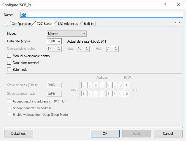
- An I2C to control the FRAM
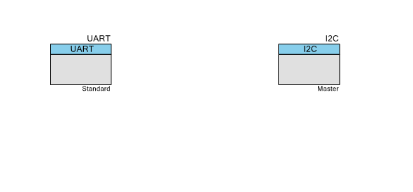
The I2C is setup as a master at it highest speed setting.
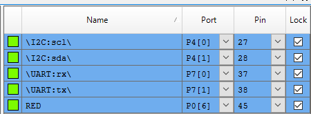
On the CY8CKIT-044 the pins need to be configured as so:
Import the FreeRTOS FAT SL FileSystem & FRAM Media Driver
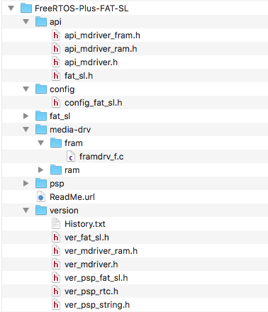
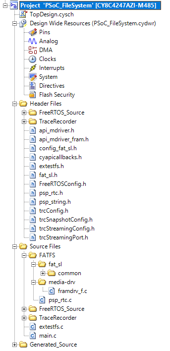
The first step in importing the FreeRTOS FAT SL FileSystem and and media driver is to copy the FreeRTOS-Plus-FAT-SL directory into my project. Once that is done, my folder structure looks like this:
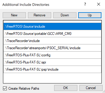
The next step is to fix the include paths to include the config, api and psp include directories. This can be done on the build settings menu.
Finally I import the .h and .c files into my project so that it looks like this:
Build a Command Line Interpreter (CLI)
I think that it is convenient to have a command line utility (one that connects to the UART port) to send commands to my program to test it. To build the CLI, I create a task called uartTask which takes keys from the terminal and then processes them in a giant switch statement. While I was building the FreeRTOS FAT SL system, I noticed that FreeRTOS also has a scheme for CLIs which I will try out in the future.
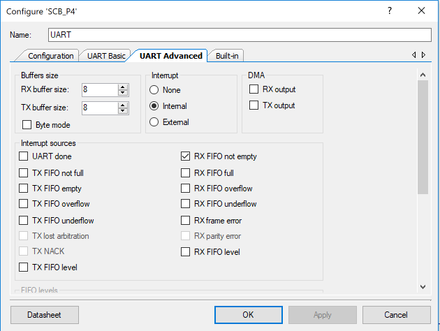
In the UART configuration I turn on the “RX FIFO not empty” interrupt (meaning that there is data in the fifo that needs to be processed)
I connect the interrupt to the interrupt service routine on line 64. In the ISR I use the FreeRTOS notification scheme to send notifications to the uartTask to wakeup and process data (line 50).
My CLI has two different things that it does:
- It calls functions in the file extestfs.c that start with “ex” , meaning example, to format, initalize etc.
- It keeps a “currentSector” variable that lets me print out the raw data in a sector. The currentSector variable is incremented (with the keyboard +) and decremented (with the keyboard -) and set to 0 with the (keyboard 0)
Once all of the keys have been processed (the Rx FIFO buffer is empty – line 71), it turns back on the Rx FIFO interrupt (lines 150-151), then waits for another notification from the ISR (line 69)
TaskHandle_t uartTaskHandle;
void uartISR()
{

    BaseType_t xHigherPriorityTaskWoken;
    // disable the interrupt
    UART_SetRxInterruptMode(0);
    vTaskNotifyGiveFromISR(uartTaskHandle,&xHigherPriorityTaskWoken);
    portYIELD_FROM_ISR( xHigherPriorityTaskWoken );

}

// This is the main task which processes commands from the UART and prints the results
// on the screen.
void uartTask(void *arg)
{
    (void)arg;
    UART_Start();
    I2C_Start();
    clearScreen();
    UART_UartPutString("Start Filesystem Demo\n");
    UART_SetCustomInterruptHandler(uartISR);

    int currentSector=0;
    while(1)
    {
        ulTaskNotifyTake(pdTRUE,portMAX_DELAY);

        while(UART_SpiUartGetRxBufferSize()) // if there is data then read and process
        {
            char c;

            c= UART_UartGetChar();
			switch(c)
			{
				case 'i': // Initialize the RTOS
					exInit();
				break;
				case 'f': // Format the FRAM
					exFormat();
				break;

				case 'q': // Return the drive information
					exDriveInfo();
				break;

                case 'w': // Create a file
				    exCreateFile();
				break;

				case 'r': // Read the file that was created (if it exists)
				    exReadFile();
				break;

				case '0': // Goto to sector 0 and print the data
				    currentSector = 0;
					exPrintSector(0,0,0);
				break;

			    case '+': // Print the "current" sector and go to the next
				    exPrintSector(0,0,currentSector);
				    currentSector += 1;
			    break;

			    case '-': // print the current sector and go to the previous
				    exPrintSector(0,0,currentSector);
				    currentSector -= 1;
				    if(currentSector<0)
					    currentSector =0;
			    break;

    			case 'd': // Do a directory
	    			exDirectory();
		    	break;

                case 'c':
                    clearScreen();
                break;

                case 'b': // Erase the FRAM (write all 0's)
                    blankFRAM();
                break;

                case '?': // Print out the list of commands
                    UART_UartPutString("b - Blank FRAM - write all 0's\n");
                    UART_UartPutString("i - Initalize Filesystem\n");
                    UART_UartPutString("f - Format FRAM\n");
                    UART_UartPutString("q - Print FileSystem Information\n");
                    UART_UartPutString("w - Create a file called \"afile.bin\"\n");
                    UART_UartPutString("r - Read the file called \"afile.bin\" and print contents\n");
                    UART_UartPutString("0 - Goto sector 0 and print contents\n");
                    UART_UartPutString("+ - Goto next sector and print contents\n");
                    UART_UartPutString("- - Goto previous sector and print contents\n");
                    UART_UartPutString("d - Print Directory\n");
                    UART_UartPutString("c - Clear Screen\n");
                    UART_UartPutString("? - Print help\n");

                break;

			    default:
				    UART_UartPutString("Unknown :");
				    UART_UartPutChar(c);
				    UART_UartPutChar('\n');
			    break;
			}
        }
        // Turn the interrupts back on
        UART_ClearRxInterruptSource(UART_INTR_RX_NOT_EMPTY);
        UART_SetRxInterruptMode(UART_INTR_RX_NOT_EMPTY);
    }
}
Nuke the FRAM Data
I thought that it would be a good idea to have a function to put 0’s in all of the locations in the FRAM, to prove that I could start with a clean slate. This function does just that. Specifically it write 0’s to the 64K locations in I2C address 0x50 (the first bank) and to I2C address 0x51 (the second bank)
// This function erases - write 0's into the FRAM... also known as NUKE the FRAM
void blankFRAM(void)
{
    int i;
    UART_UartPutString("Starting Erase 1st Block\n");
    I2C_I2CMasterSendStart(0x50,I2C_I2C_WRITE_XFER_MODE);
    I2C_I2CMasterWriteByte(0);
    I2C_I2CMasterWriteByte(0);
    for(i=0;i<0xFFFF;i++) // Write 64K of 0's to erase first bank
    {
        I2C_I2CMasterWriteByte(0);
    }
    I2C_I2CMasterSendStop();
    UART_UartPutString("Starting Erase 2nd Block\n");
    I2C_I2CMasterSendStart(0x51,I2C_I2C_WRITE_XFER_MODE);
    I2C_I2CMasterWriteByte(0);
    I2C_I2CMasterWriteByte(0);
    for(i=0;i<0xFFFF;i++) // write 64k of 0's to erase 2nd bank
    {
        I2C_I2CMasterWriteByte(0);
    }
    I2C_I2CMasterSendStop();

    UART_UartPutString("Erase Complete\n");

}
As always you can find this project on the IoT Expert GitHub site git@github.com:iotexpert/PSoC-FileSystem.git

No comment yet, add your voice below!