Mouser PSoC 6-WiFi-BT L0 : Designing low-power, cloud-connected IoT devices with PSoC® 6 MCU’s and WICED® Wi-Fi/Bluetooth

Summary

Hello everyone.  This is lesson 0 of a series of 9 lessons about creating applications for the Cypress CY8CKIT-062-WiFi-BLE development kit.  The marketing guys call the class “Designing low-power, cloud-connected IoT devices with PSoC® 6 MCU’s and WICED® Wi-Fi/Bluetooth” … which although a really long name, is a good description of what we are going to do.

What I will do today is take you lesson by lesson through the class and talk about how it all works and what you need to do.  When I built the class it was absolutely my goal to have every button click and line of code described.  That being said,  it is likely that I made some errors.  So, during the class you will be able to send messages to my team who will answer the questions, or ask me and Ill answer live.  If you missed the class, that’s OK, you will be able to watch it on replay.  In addition if you have a question after the live stream is over, leave a comment here and Ill answer.

I will attempt to go slowly enough for you to follow along, but if I go to fast, don’t worry you should be able to follow along with the instructions on this website.

Todays virtual workshop is going to go like this.  Every lesson will have this table in it and you will be able to click to the right place.

Designing low-power, cloud-connected IoT devices with PSoC® 6 MCU’s and WICED® Wi-Fi/Bluetooth

You will need a few things for this class:

  • CY8CKIT-062-WiFi-BT
  • WICED Studio 6.2
  • CySmart or LightBlue a BLE
  • GoBle an iOS Remote Control App
  • An Amazon AWS IoT Account
  • A WiFi Access Point connected to the Internet

CY8CKIT-062-WiFi-BT

All of the projects in this series of lesson will be built to be programmed onto a CY8CKIT-062-WiFi-BT.  You can get the development kit from Mouser.  This development kit has a bunch of cool stuff including

  • PSoC 6 – The lowest power, most secure MCU for the IoT
  • CYW4343W – A WICED WiFi Bluetooth Combo Radio
  • S25FL512SAGMFI011 – A Cypress 512Mb Quad SPI Flash
  • CCG2 – A Cypress Type C Controller to manage Power

The CY8CKIT-028-TFT a full color 320×240 TFT display with an ST7789S display controller.

Here is the whole thing together

WICED Studio 6.2

This class is build around WICED Studio 6.2, the Cypress IDE built on top of Eclipse.  WICED Studio has all of the tools, examples and SDKs to build projects for the Cypress WICED Bluetooth and WiFi products.  We support Windows, Mac and Linux and you can download it from our community website: https://community.cypress.com/community/wireless (which I hope you have done by now)

CySmart or LightBlue a BLE

CySmart is a BLE GATT Browser which you can get from the iOS App store or the Google Play store


GoBle an iOS Remote Control App

GoBle is a Robot Remote Control App which can be downloaded from the iOS App Store.

An Amazon AWS IoT Account

In order to connect Amazon AWS IoT you will need to create an Amazon AWS Account.  It is essentially free to test you simple applications (obviously there are fees if you deploy many devices)


Mouser Video Training Workshop – October 24

On October 24, I will be teaching a Mouser video training workshop … live streaming on the internet.  The workshop will be about PSoC, WICED, WiFi and Bluetooth.  I am going to show PSoC Creator, WICED Studio and Cypress’s new development tool Modus Toolbox.

You can register for the workshop at this link.

I am going to build the whole class around the CY8CKIT-062-BLE-WiFi Development Kit.  You can get the devlopment kit from Mouser.

Here is the introduction:


WICED 20719 BLE Central Custom Profile w/LED & CapSense – Part 2

Summary

In the previous article I showed you how to create a BLE Central that could attach to a BLE peripheral that is advertising a custom service.  Then, I showed you how to write values to the LED Characteristic in the Peripheral GATT Server.  In this article Ill show you how to set the CCCD and what happens when the Peripheral notifies.

The steps to build this project will be as follows

  1. Create a new project with copy/paste
  2. Write the CCCD
  3. Handle the new GATT Events

Create a new project by copy/paste

I wanted to have three different projects for each of the steps in this series of articles.  To create the 2nd example (the subject of this article) Ill just do a copy/paste and then fix a few things.  Start with the copy.

When you paste it will ask you to give a new name to the directory.

Give the main file a new name, in this case ex02CCCD.c

And create a new make target.

Fix the makefile with the new name of the source file.

Build and test to make sure that everything still works…. and it seems to.

Write the CCCD

The Peripheral that we are talking to in this example has a CapSense Characteristic that has a Client Characteristic Configuration Descriptors, also known as the CCCD.   When you set the CCCD to 1, the Peripheral will then send you notifications anytime the underlying Characteristic changes.  WICED has some utility functions to help you interact with the remote GATT server.  To add them to your project, first include the header file.

#include "wiced_bt_gatt_util.h"

Then modify your makefile to include the library.

$(NAME)_COMPONENTS += gatt_utils_lib.a

To actually turn on/off the CCCD you simply call the library function wiced_bt_util_set_gatt_client_config_descriptor.  Ill add a case ‘n’ to turn on notifications and a case ‘N’ to turn them off.  Notice the 0x12 is hardcoded in two places, something which is really bad and Ill fix in the next article.  Don’t forget to add the two cases to the help message.

     case 'n':
         WICED_BT_TRACE("CCCD On\n");
         if(conn_id )
             wiced_bt_util_set_gatt_client_config_descriptor(conn_id,0x12,1); // Very bad hardcode 0x12

         break;

     case 'N':
         WICED_BT_TRACE("CCCD Off\n");
         if(conn_id )
             wiced_bt_util_set_gatt_client_config_descriptor(conn_id,0x12,0); // Very bad hardcode 0x12
         break;


    case '?':
        /* Print help */
        WICED_BT_TRACE( "\n" );
        WICED_BT_TRACE( "+------- Available Commands -------+\n" );
        WICED_BT_TRACE( "|  n    CCCD On                    |\n" );
        WICED_BT_TRACE( "|  N    CCCD Off                   |\n" );

Now when I test… I can press the ‘n’ to set the CCCD.  When I touch the CapSense slider I seem to get a whole bunch of “Unknown GATT Event 1″s (we will figure that out in just a bit).  So it seems to be working.  When I press ‘N’ I don’t get the messages.


Is there something special about the function wiced_bt_util_set_gatt_client_config_descriptor?  Nope.  If you right click on it, you can look at the source code.  This code looks exactly like the “writeLed” function that we wrote in the previous example.  The only difference is that instead of allocating a buffer using wiced_bt_get_buffer the author of this function allocated the buffer on the stack.

/*
 * Format and send GATT Write Request to set value of a G
 */
wiced_bt_gatt_status_t wiced_bt_util_set_gatt_client_config_descriptor(uint16_t conn_id, uint16_t handle, uint16_t value)
{
    wiced_bt_gatt_status_t status;
    uint8_t                buf[sizeof(wiced_bt_gatt_value_t) + 1];
    wiced_bt_gatt_value_t *p_write = ( wiced_bt_gatt_value_t* )buf;
    uint16_t               u16 = value;

    // Allocating a buffer to send the write request
    memset(buf, 0, sizeof(buf));

    p_write->handle   = handle;
    p_write->offset   = 0;
    p_write->len      = 2;
    p_write->auth_req = GATT_AUTH_REQ_NONE;
    p_write->value[0] = u16 & 0xff;
    p_write->value[1] = (u16 >> 8) & 0xff;

    // Register with the server to receive notification
    status = wiced_bt_gatt_send_write (conn_id, GATT_WRITE, p_write);
    return status;
}

Handle the new GATT Events

In the screenshot of the serial terminal above you can see a bunch of “Unknown GATT Event 1”.  What is that?  To figure that out, right click on the GATT_CONNECTION_EVT and go to declaration.

This will take you to this enumeration, which shows all of the possible GATT events.  And, in this table you can see that 0x01 is GATT_OPERATION_CPLT_EVT.

/** GATT events */
typedef enum
{
    GATT_CONNECTION_STATUS_EVT,                         /**< GATT connection status change. Event data: #wiced_bt_gatt_connection_status_t */
    GATT_OPERATION_CPLT_EVT,                            /**< GATT operation complete. Event data: #wiced_bt_gatt_event_data_t */
    GATT_DISCOVERY_RESULT_EVT,                          /**< GATT attribute discovery result. Event data: #wiced_bt_gatt_discovery_result_t */
    GATT_DISCOVERY_CPLT_EVT,                            /**< GATT attribute discovery complete. Event data: #wiced_bt_gatt_event_data_t */
    GATT_ATTRIBUTE_REQUEST_EVT,                         /**< GATT attribute request (from remote client). Event data: #wiced_bt_gatt_attribute_request_t */
    GATT_CONGESTION_EVT                                 /**< GATT congestion (running low in tx buffers). Event data: #wiced_bt_gatt_congestion_event_t */
} wiced_bt_gatt_evt_t;

So, lets update the GATT Event handler for that case.  What Ill do is just printout the information that is sent (which is of type wiced_bt_gatt_event_data_t).

    case GATT_OPERATION_CPLT_EVT:

        // When you get something back from the peripheral... print it out.. and all of its data

        WICED_BT_TRACE("Gatt Event Complete Conn=%d Op=%d status=0x%X Handle=0x%X len=%d Data=",
                p_data->operation_complete.conn_id,
                p_data->operation_complete.op,
                p_data->operation_complete.status,
                p_data->operation_complete.response_data.handle,
                p_data->operation_complete.response_data.att_value.len);

        for(int i=0;i<p_data->operation_complete.response_data.att_value.len;i++)
        {
            WICED_BT_TRACE("%02X ",p_data->operation_complete.response_data.att_value.p_data[i]);
        }
        WICED_BT_TRACE("\n");

        break;

After I program the CYW920719Q40EVB_01 you can see that things seem to be working.  Specifically, I found the peripheral, connected to it, set the CCCD for CapSense, then pressed the CapSense slider on the Peripheral.  Notice that after I set the CCCD, I get an event complete with op=3 and handle=0x12.  This is the write response message for the CCCD handle. (remember the hardcoded 0x12 from above).

The other thing to see is that each time there is CapSense update, the Peripheral sends out a notification of handle 0x11 with the current CapSense slider value.  Notice that the slider value is little endian.  You can see the last value is 0xFFFF which is a no touch in CapSense.

The “op” is just one of the enumerated values from the list below.  You can see the 0x06 is Notification.  And 0x03 is Write.

/** GATT client operation type, used in client callback function
*/
enum wiced_bt_gatt_optype_e
{
    GATTC_OPTYPE_NONE             = 0,    /**< None      */
    GATTC_OPTYPE_DISCOVERY        = 1,    /**< Discovery */
    GATTC_OPTYPE_READ             = 2,    /**< Read      */
    GATTC_OPTYPE_WRITE            = 3,    /**< Write     */
    GATTC_OPTYPE_EXE_WRITE        = 4,    /**< Execute Write */
    GATTC_OPTYPE_CONFIG           = 5,    /**< Configure */
    GATTC_OPTYPE_NOTIFICATION     = 6,    /**< Notification */
    GATTC_OPTYPE_INDICATION       = 7     /**< Indication */
};

You can find all of the source code for these projects at github.com/iotexpert/PSoc4BLE-Central 

IoT Mailbox: An Introduction

Summary

On the days that my newspaper carrier decides to deliver the newspaper, you can be sure that it won’t be there before 4:00am or after 10:00am.  Why do I still get a newspaper?  Because my wife likes it.  The status of the delivery is a constant source of speculation in the morning.  Have you been out to the newspaper box?  Will you go?  etc.  So it seems only logical to make an IoT device that figures out if I have a newspaper.  Obviously this is a bit silly to put as much time and effort as I have into that simple task.  But, doing something cool has it own worth.  And it will give me a chance to use the new WICED XR (extended range) Bluetooth radio module CYBT-483039-02.

And here is a picture of the new module on the CYBT-483039-EVAL EZ-BT evaluation kit.

For this design I want

  1. A newspaper sensor (not sure what that will be)
  2. Waterproof case
  3. A temperature sensor
  4. A custom circuit board
  5. A solar battery charger
  6. The ability to program and debug the 20719 (which will be acting as a beacon)
  7. An OTA Bootloader
  8. A Real Time Clock
  9. A wifi/ble bridge (inside the house)
  10. Some cloud data capture and display
  11. An iOS App

So far, this project has been quite a rabbit hole as I don’t/didn’t know anything about battery power supplies.  Specifically energy harvesting solar powered lithium ion battery chargers and system power supply.  Unfortunately Cypress doesnt make an IC that performs this application … so if you send Mouser a few hundred dollars and they will send you a box of a bunch of different Solar PMIC Evaluation kits, ST, TI, Linear, Analog Devices, and Microchip. (which I will write about in detail later)

Architecture

Here is a picture of the architecture.

In the next Article I will start the process of learning about Solar Battery Charging PMICs.

Article Description
IoT Mailbox Introduction An introduction to the long series of articles about creating a new IoT System.
IoT Mailbox: Solar Battery Chargers & System Power Supplies

Lesson 9 – WICED Bluetooth: Classic Serial Port

WICED Bluetooth Using the CYW20719

# Title Comment
0 A Two Hour WICED Bluetooth Class WICED Bluetooth Using the CYW20719 in all its glory
1 Resources Links to all of the Cypress WICED information including videos, application notes etc.
2 Your First Project Making Hello World & the Blinky LED
3 The Super Mux Tool Learning about platforms and the Super Mux Tool
4 Snips Using the example projects to learn Bluetooth
5 Bluetooth Designer Using the tool to customize a project and get going fast
6 The CCCD & Notification Writing back to the Central
7 Advertising  Beacon Building a beacon project to advertise your custom information 
8 Scanner Viewing the world around you
9 Bluetooth Classic SPP Using the Serial Port Profile to Transmit Lots of Data

Source code: 

  • git@github.com:iotexpert/wiced_bt_intro.git
  • https://github.com/iotexpert/wiced_bt_intro


Summary

In all of the previous examples I have been using Bluetooth Low Energy.  One of the great benefits of the Cypress CYW20719 is that it is a Combo Radio.  Combo means that it can use both Bluetooth Low Energy as well as Bluetooth Classic.  I am late to the Bluetooth game but as best I can tell Bluetooth Classic and Bluetooth Low Energy are exactly the same … except everything is different.  When Bluetooth was originally conceived, one of the principal functions was to act as “serial port wire cutter”.  Everywhere you looked there were devices that used a serial port wire, e.g. mice, printers, keyboards etc.

For this lesson we are going to dip back into the snip directory to get a Bluetooth Classic program to start with.  The program snip.bt.spp implements the Serial Port Profile (SPP).  The SPP is emulates a classic serial port.  It has all of the uart wires that we know and love including rx,tx,cts etc.  What this allows you to do is open up a high speed (much faster than BLE) connection.

To implement this lesson I will perform the following steps

  1. Make a new folder in the wiced_bt_class folder
  2. Copy the files from apps/snip/bt/spp into my new folder
  3. Create a make target and program it
  4. Make a connection using a Bluetooth serial port on my Mac
  5. Look at where the pin is set
  6. Examine the spp setup code
  7. Modify it to print out all the data sent to the SPP

Implement the SPP


Set the folder name to “spp”

Copy and past the files from the folder apps.snip.bt.spp


And paste them into your new spp folder

Create a make target for your spp project

Program the board with your project

Now tell the computer to open a classic connection by running file->open bluetooth

Select the “spp test”

Now press some keys on the new terminal window… and look at the output window of the “spp test”

Type in the pin code which is 0000.

But, how did I know the pin code?  Look at the source code.

uint8_t pincode[4] = { 0x30, 0x30, 0x30, 0x30 };

Now, when you press keys on the “Bluetooth serial terminal” you will see a not very helpful message on the CYW920719Q40EVB-01 terminal window.

I think that it would be better to print out the characters that the person types.  So lets figure out how this works.  In the application init function on line 251 there is a call to wiced_bt_spp_startup

void application_init(void)
{
    wiced_bt_gatt_status_t gatt_status;
    wiced_result_t         result;


#if SEND_DATA_ON_INTERRUPT
    /* Configure the button available on the platform */
    wiced_platform_register_button_callback( WICED_PLATFORM_BUTTON_1, app_interrupt_handler, NULL, WICED_PLATFORM_BUTTON_RISING_EDGE);

    // init timer that we will use for the rx data flow control.
    wiced_init_timer(&app_tx_timer, app_tx_ack_timeout, 0, WICED_MILLI_SECONDS_TIMER);
#endif

    app_write_eir();


    // Initialize SPP library
    wiced_bt_spp_startup(&spp_reg);

That function takes a pointer to a structure with a bunch of interesting things in it.  Notice that there is a function called “spp_rx_data_callback” that is called every time that data come in from the SPP.

wiced_bt_spp_reg_t spp_reg =
{
    SPP_RFCOMM_SCN,                     /* RFCOMM service channel number for SPP connection */
    MAX_TX_BUFFER,                      /* RFCOMM MTU for SPP connection */
    spp_connection_up_callback,         /* SPP connection established */
    NULL,                               /* SPP connection establishment failed, not used because this app never initiates connection */
    NULL,                               /* SPP service not found, not used because this app never initiates connection */
    spp_connection_down_callback,       /* SPP connection disconnected */
    spp_rx_data_callback,               /* Data packet received */
};

Now look at the function spp_rx_data_callback.  All it does is print out a message saying how much data and the hex value of the data.

wiced_bool_t spp_rx_data_callback(uint16_t handle, uint8_t* p_data, uint32_t data_len)
{
    int i;
//    wiced_bt_buffer_statistics_t buffer_stats[4];

//    wiced_bt_get_buffer_usage (buffer_stats, sizeof(buffer_stats));

//    WICED_BT_TRACE("0:%d/%d 1:%d/%d 2:%d/%d 3:%d/%d\n", buffer_stats[0].current_allocated_count, buffer_stats[0].max_allocated_count,
//                   buffer_stats[1].current_allocated_count, buffer_stats[1].max_allocated_count,
//                   buffer_stats[2].current_allocated_count, buffer_stats[2].max_allocated_count,
//                   buffer_stats[3].current_allocated_count, buffer_stats[3].max_allocated_count);

//    wiced_result_t wiced_bt_get_buffer_usage (&buffer_stats, sizeof(buffer_stats));

    WICED_BT_TRACE("%s handle:%d len:%d %02x-%02x\n", __FUNCTION__, handle, data_len, p_data[0], p_data[data_len - 1]);

#if LOOPBACK_DATA
    wiced_bt_spp_send_session_data(handle, p_data, data_len);
#endif
    return WICED_TRUE;
}

So,  How about instead of that message we just print out the data.

    //WICED_BT_TRACE("%s handle:%d len:%d %02x-%02x\n", __FUNCTION__, handle, data_len, p_data[0], p_data[data_len - 1]);

    for(int i=0;i<data_len;i++)
        WICED_BT_TRACE("%c",p_data[i]);

Now when I run the project and type I see the characters that I type coming out on the serial port.

Lesson 8 – WICED Bluetooth: The Advertising Scanner

WICED Bluetooth Using the CYW20719

# Title Comment
0 A Two Hour WICED Bluetooth Class WICED Bluetooth Using the CYW20719 in all its glory
1 Resources Links to all of the Cypress WICED information including videos, application notes etc.
2 Your First Project Making Hello World & the Blinky LED
3 The Super Mux Tool Learning about platforms and the Super Mux Tool
4 Snips Using the example projects to learn Bluetooth
5 Bluetooth Designer Using the tool to customize a project and get going fast
6 The CCCD & Notification Writing back to the Central
7 Advertising  Beacon Building a beacon project to advertise your custom information 
8 Scanner Viewing the world around you
9 Bluetooth Classic SPP Using the Serial Port Profile to Transmit Lots of Data

Source code: 

  • git@github.com:iotexpert/wiced_bt_intro.git
  • https://github.com/iotexpert/wiced_bt_intro


Summary

In the last lesson I showed you how to build a BLE Advertising Beacon.  In that lesson I used a program called the “AdvScanner” which ran on a CYW920719Q40EVB-01 and acted like a Bluetooth Sniffer.  In this lesson I’ll show you how to build a simpler version of that program to look for the L7_Advertiser we built in the last lesson.

The important concepts in this lesson are:

  1. BLE Scanning
  2. Parsing Advertising Packets

I am going to build a project that Scans for BLE Advertisers.  Then, I’ll add the ability to print out the advertising packet.  And finally, I will add filtering capability to only look for advertisers who are using the Cypress Manufacturers code.

The steps that we will follow are:

  1. Make a new project with WICED Bluetooth Designer called L8_Scanner
  2. Turn off the GATT Database
  3. Move it into your project folder
  4. Fix the WICED_BT_TRACE to use the PUART
  5. Create a make target and build it
  6. Add a new function that prints out Advertising Packets
  7. Update the l8_scanner_app_init function to remove Advertising
  8. Update the wiced_bt_config to never stop scanning
  9. Program the development kit and see what happens
  10. Update the newAdv function to print out the raw data in the advertising packet
  11. Program again and see all of the chaos
  12. Put a filter for the Advertisers using the Cypress MFG Code
  13. Program

Implement the Project

Create a new project called L8_Scanner using the Bluetooth Designer

Turn off the GATT Database and then press Generate Code

Move the project into the wiced_bt_class folder

Update the WICED_BT_TRACE to send output to the PUART

#if ((defined WICED_BT_TRACE_ENABLE) || (defined HCI_TRACE_OVER_TRANSPORT))
    /* Set the Debug UART as WICED_ROUTE_DEBUG_NONE to get rid of prints */
    //  wiced_set_debug_uart( WICED_ROUTE_DEBUG_NONE );

    /* Set Debug UART as WICED_ROUTE_DEBUG_TO_PUART to see debug traces on Peripheral UART (PUART) */
      wiced_set_debug_uart( WICED_ROUTE_DEBUG_TO_PUART );

    /* Set the Debug UART as WICED_ROUTE_DEBUG_TO_WICED_UART to send debug strings over the WICED debug interface */
    //wiced_set_debug_uart( WICED_ROUTE_DEBUG_TO_WICED_UART );
#endif

Modify the make target & program that was created by the BT Designer

Make a new function that will be called when WICED finds a new advertising packet.

void newAdv(wiced_bt_ble_scan_results_t *p_scan_result, uint8_t *p_adv_data)
{
    WICED_BT_TRACE("Found device %B\n",p_scan_result->remote_bd_addr);

}

Remove the start advertising from l8_scanner_app_init

/*
 * This function is executed in the BTM_ENABLED_EVT management callback.
 */
void l8_scanner_app_init(void)
{
    /* Initialize Application */
    wiced_bt_app_init();

    /* Allow peer to pair */
    wiced_bt_set_pairable_mode(WICED_TRUE, 0);

    /* Set Advertisement Data */
    //l8_scanner_set_advertisement_data();

    /* Start Undirected LE Advertisements on device startup.
     * The corresponding parameters are contained in 'wiced_bt_cfg.c' */
    /* TODO: Make sure that this is the desired behavior. */
    //wiced_bt_start_advertisements(BTM_BLE_ADVERT_UNDIRECTED_HIGH, 0, NULL);
    wiced_bt_ble_scan(BTM_BLE_SCAN_TYPE_HIGH_DUTY,FALSE,newAdv);
}

Update wiced_bt_config.c to never stop scanning.

        .high_duty_scan_duration =          0,                                                          /**< High Duty Scan Duration in seconds (0 for infinite) */

Program your development kit and see what happens.

Now lets update the program to print the advertising packets.

void newAdv(wiced_bt_ble_scan_results_t *p_scan_result, uint8_t *p_adv_data)
{

    uint8_t mfgLen;
    uint8_t* mfgData = wiced_bt_ble_check_advertising_data( p_adv_data,0xFF,&mfgLen);


    WICED_BT_TRACE("Found device %B ",p_scan_result->remote_bd_addr);

    uint8_t index=0;
    int fieldLength=p_adv_data[index];
    do {
        for(int i=0;i<=fieldLength;i++)
            WICED_BT_TRACE("%02X ",p_adv_data[index+i]);

        index = index + fieldLength + 1;
        fieldLength = p_adv_data[index];

    } while(fieldLength);

    WICED_BT_TRACE("\n");
}

Now program the development kit and see what happens.  Where I am sitting this is not very helpful because there are boatloads of advertisers.

Now let’s make one more change.  Instead of printing all of the packets let’s only look only at the ones that have Manufacturer data, the right length and the Cypress manufacturer id.

    uint8_t mfgLen;
    uint8_t* mfgData = wiced_bt_ble_check_advertising_data( p_adv_data,0xFF,&mfgLen);

    if(!(mfgData && mfgLen == 3 && mfgData[0] == 0x31 && mfgData[1]  == 0x01 ))
        return;

Now I only see my L7_Advertising project

Lesson 7 – WICED Bluetooth: Bluetooth Advertising

WICED Bluetooth Using the CYW20719

# Title Comment
0 A Two Hour WICED Bluetooth Class WICED Bluetooth Using the CYW20719 in all its glory
1 Resources Links to all of the Cypress WICED information including videos, application notes etc.
2 Your First Project Making Hello World & the Blinky LED
3 The Super Mux Tool Learning about platforms and the Super Mux Tool
4 Snips Using the example projects to learn Bluetooth
5 Bluetooth Designer Using the tool to customize a project and get going fast
6 The CCCD & Notification Writing back to the Central
7 Advertising  Beacon Building a beacon project to advertise your custom information 
8 Scanner Viewing the world around you
9 Bluetooth Classic SPP Using the Serial Port Profile to Transmit Lots of Data

Source code: 

  • git@github.com:iotexpert/wiced_bt_intro.git
  • https://github.com/iotexpert/wiced_bt_intro


Summary

Everywhere you go there are bunches of Bluetooth devices that are acting as beacons.  Apple has a standard called iBeacon.  Google has a standard called Eddystone.  Some companies use those standards, and some companies make proprietary beacons.  In this lesson we will build a beacon.

The important concepts in this lesson are:

  1. Advertising packet formats
  2. wiced_bt_cfg.c

The steps I will follow are:

  1. Run BT Designer
  2. Setup the device as “no gatt database”
  3. Move the project into the wiced_bt_class folder
  4. Edit the make target
  5. Fix the WICED_BT_TRACE to go to the PUART
  6. Run it
  7. Edit the wiced_bt_cfg.c to never timeout
  8. Setup no random address changing
  9. Add the manufacturing data uint8_t array and include the Cypress company code
  10. Change the start advertising call to BTM_BLE_ADVERT_NONCONN_HIGH, BLE_ADDR_PUBLIC
  11. Update the length of the advertising packet
  12. Update the set advertising packet to have the manufacturing data
  13. Add a button interrupt function
  14. Register the button interrupt

BLE Concepts

The Advertising Packet is a string of 3-31 bytes that is broadcast at a configurable interval. The packet is broken up into variable length fields. Each field has the form:

  • Length in bytes (not including the Length byte)
  • Type
  • Optional Data

The minimum packet requires the <<Flags>> field which is a set of flags that defines how the device behaves (e.g. is it connectable?). Here is a list of the other field Types that you can add:

/** Advertisement data types */
enum wiced_bt_ble_advert_type_e {
BTM_BLE_ADVERT_TYPE_FLAG                        = 0x01,                 /**< Advertisement flags */
BTM_BLE_ADVERT_TYPE_16SRV_PARTIAL               = 0x02,                 /**< List of supported services - 16 bit UUIDs (partial) */
BTM_BLE_ADVERT_TYPE_16SRV_COMPLETE              = 0x03,                 /**< List of supported services - 16 bit UUIDs (complete) */
BTM_BLE_ADVERT_TYPE_32SRV_PARTIAL               = 0x04,                 /**< List of supported services - 32 bit UUIDs (partial) */
BTM_BLE_ADVERT_TYPE_32SRV_COMPLETE              = 0x05,                 /**< List of supported services - 32 bit UUIDs (complete) */
BTM_BLE_ADVERT_TYPE_128SRV_PARTIAL              = 0x06,                 /**< List of supported services - 128 bit UUIDs (partial) */
BTM_BLE_ADVERT_TYPE_128SRV_COMPLETE             = 0x07,                 /**< List of supported services - 128 bit UUIDs (complete) */
BTM_BLE_ADVERT_TYPE_NAME_SHORT                  = 0x08,                 /**< Short name */
BTM_BLE_ADVERT_TYPE_NAME_COMPLETE               = 0x09,                 /**< Complete name */
BTM_BLE_ADVERT_TYPE_TX_POWER                    = 0x0A,                 /**< TX Power level  */
BTM_BLE_ADVERT_TYPE_DEV_CLASS                   = 0x0D,                 /**< Device Class */
BTM_BLE_ADVERT_TYPE_SIMPLE_PAIRING_HASH_C       = 0x0E,                 /**< Simple Pairing Hash C */
BTM_BLE_ADVERT_TYPE_SIMPLE_PAIRING_RAND_C       = 0x0F,                 /**< Simple Pairing Randomizer R */
BTM_BLE_ADVERT_TYPE_SM_TK                       = 0x10,                 /**< Security manager TK value */
BTM_BLE_ADVERT_TYPE_SM_OOB_FLAG                 = 0x11,                 /**< Security manager Out-of-Band data */
BTM_BLE_ADVERT_TYPE_INTERVAL_RANGE              = 0x12,                 /**< Slave connection interval range */
BTM_BLE_ADVERT_TYPE_SOLICITATION_SRV_UUID       = 0x14,                 /**< List of solicitated services - 16 bit UUIDs */
BTM_BLE_ADVERT_TYPE_128SOLICITATION_SRV_UUID    = 0x15,                 /**< List of solicitated services - 128 bit UUIDs */
BTM_BLE_ADVERT_TYPE_SERVICE_DATA                = 0x16,                 /**< Service data - 16 bit UUID */
BTM_BLE_ADVERT_TYPE_PUBLIC_TARGET               = 0x17,                 /**< Public target address */
BTM_BLE_ADVERT_TYPE_RANDOM_TARGET               = 0x18,                 /**< Random target address */
BTM_BLE_ADVERT_TYPE_APPEARANCE                  = 0x19,                 /**< Appearance */
BTM_BLE_ADVERT_TYPE_ADVERT_INTERVAL             = 0x1a,                 /**< Advertising interval */
BTM_BLE_ADVERT_TYPE_LE_BD_ADDR                  = 0x1b,                 /**< LE device bluetooth address */
BTM_BLE_ADVERT_TYPE_LE_ROLE                     = 0x1c,                 /**< LE role */
BTM_BLE_ADVERT_TYPE_256SIMPLE_PAIRING_HASH      = 0x1d,                 /**< Simple Pairing Hash C-256 */
BTM_BLE_ADVERT_TYPE_256SIMPLE_PAIRING_RAND      = 0x1e,                 /**< Simple Pairing Randomizer R-256 */
BTM_BLE_ADVERT_TYPE_32SOLICITATION_SRV_UUID     = 0x1f,                 /**< List of solicitated services - 32 bit UUIDs */
BTM_BLE_ADVERT_TYPE_32SERVICE_DATA              = 0x20,                 /**< Service data - 32 bit UUID */
BTM_BLE_ADVERT_TYPE_128SERVICE_DATA             = 0x21,                 /**< Service data - 128 bit UUID */
BTM_BLE_ADVERT_TYPE_CONN_CONFIRM_VAL            = 0x22,                 /**< LE Secure Connections Confirmation Value */
BTM_BLE_ADVERT_TYPE_CONN_RAND_VAL               = 0x23,                 /**< LE Secure Connections Random Value */
BTM_BLE_ADVERT_TYPE_URI                         = 0x24,                 /**< URI */
BTM_BLE_ADVERT_TYPE_INDOOR_POS                  = 0x25,                 /**< Indoor Positioning */
BTM_BLE_ADVERT_TYPE_TRANS_DISCOVER_DATA         = 0x26,                 /**< Transport Discovery Data */
BTM_BLE_ADVERT_TYPE_SUPPORTED_FEATURES          = 0x27,                 /**< LE Supported Features */
BTM_BLE_ADVERT_TYPE_UPDATE_CH_MAP_IND           = 0x28,                 /**< Channel Map Update Indication */
BTM_BLE_ADVERT_TYPE_PB_ADV                      = 0x29,                 /**< PB-ADV */
BTM_BLE_ADVERT_TYPE_MESH_MSG                    = 0x2A,                 /**< Mesh Message */
BTM_BLE_ADVERT_TYPE_MESH_BEACON                 = 0x2B,                 /**< Mesh Beacon */
BTM_BLE_ADVERT_TYPE_3D_INFO_DATA                = 0x3D,                 /**< 3D Information Data */
BTM_BLE_ADVERT_TYPE_MANUFACTURER                = 0xFF                  /**< Manufacturer data */
};

Here is an example of the advertising packet that we are going to generate

Implement the Project

Run BT Designer and create a new project called “L7_Advertising”

Turn off the GATT Database

Move the project into the wiced_bt_class folder

Edit the make target

Setup the the WICED_BT_TRACE to use the PUART

#if ((defined WICED_BT_TRACE_ENABLE) || (defined HCI_TRACE_OVER_TRANSPORT))
/* Set the Debug UART as WICED_ROUTE_DEBUG_NONE to get rid of prints */
//  wiced_set_debug_uart( WICED_ROUTE_DEBUG_NONE );
/* Set Debug UART as WICED_ROUTE_DEBUG_TO_PUART to see debug traces on Peripheral UART (PUART) */
wiced_set_debug_uart( WICED_ROUTE_DEBUG_TO_PUART );
/* Set the Debug UART as WICED_ROUTE_DEBUG_TO_WICED_UART to send debug strings over the WICED debug interface */
//wiced_set_debug_uart( WICED_ROUTE_DEBUG_TO_WICED_UART );
#endif

Run it

Now that we know it is working, Ill edit the wiced_bt_cfg.c to never timeout

        .high_duty_nonconn_duration =       0,                                                         /**< High Duty Non-Connectable Advertising Duration in seconds (0 for infinite) */

Setup no random address changing

    .rpa_refresh_timeout =                  WICED_BT_CFG_DEFAULT_RANDOM_ADDRESS_NEVER_CHANGE,         /**< Interval of random address refreshing - secs */

Now edit the L7_Advertising.c to add the manufacturing data uint8_t array

uint8_t manuf_data[] = {0x31,0x01,0x00};

Switch to non-connectable advertising

    wiced_bt_start_advertisements(BTM_BLE_ADVERT_NONCONN_HIGH, BLE_ADDR_PUBLIC, NULL);

Update the l7_advertising_set_advertisement_data function to have three elements in the advertising packet

    wiced_bt_ble_advert_elem_t adv_elem[3] = { 0 };

Add the Manufacturer information to the advertising packet

    /* Advertisement Element for Manufacturer Data */
adv_elem[num_elem].advert_type = BTM_BLE_ADVERT_TYPE_MANUFACTURER;
adv_elem[num_elem].len = sizeof(manuf_data);
adv_elem[num_elem].p_data = manuf_data;
num_elem++;

Add a button interrupt function

void buttonISR(void *data, uint8_t port_pin )
{
manuf_data[2] += 1;
l7_advertising_set_advertisement_data();
WICED_BT_TRACE("Manufacturer Data = %d\n",manuf_data[2]);
}

Register the button interrupt

 wiced_hal_gpio_register_pin_for_interrupt( WICED_GPIO_PIN_BUTTON_1, buttonISR, NULL );
wiced_hal_gpio_configure_pin( WICED_GPIO_PIN_BUTTON_1, ( GPIO_INPUT_ENABLE | GPIO_PULL_UP | GPIO_EN_INT_FALLING_EDGE ), GPIO_PIN_OUTPUT_HIGH );

Test using the AdvScanner

I have given you a project called the “AdvScanner”.  You can run it by creating a make target.

When I run the L7_Advertising project and press the buttons a few times my terminal will look like this

And when I look at the output of the scanner program you can see the advertising packet for the this project.  Notice that the last three bytes are 31 01 03.  The 03 is the count of button presses.

Lesson 6 – WICED Bluetooth: The Peripheral Comes Alive

WICED Bluetooth Using the CYW20719

# Title Comment
0 A Two Hour WICED Bluetooth Class WICED Bluetooth Using the CYW20719 in all its glory
1 Resources Links to all of the Cypress WICED information including videos, application notes etc.
2 Your First Project Making Hello World & the Blinky LED
3 The Super Mux Tool Learning about platforms and the Super Mux Tool
4 Snips Using the example projects to learn Bluetooth
5 Bluetooth Designer Using the tool to customize a project and get going fast
6 The CCCD & Notification Writing back to the Central
7 Advertising  Beacon Building a beacon project to advertise your custom information 
8 Scanner Viewing the world around you
9 Bluetooth Classic SPP Using the Serial Port Profile to Transmit Lots of Data

Source code: 

  • git@github.com:iotexpert/wiced_bt_intro.git
  • https://github.com/iotexpert/wiced_bt_intro


Summary

In the last lesson we built our first Bluetooth design using BT Designer.  In that lesson I showed you how to

  1. Build a project using BT Designer
  2. Start Advertising
  3. Get connected Central –> Peripheral
  4. Read & Write the data from the Central to the  Peripheral

In this lesson we are going to answer the question how does the Peripheral write data back to the Central by adding a button to our last project.  When the button is pressed it will send the state of the button (0 or 1) back to Central.

The important concepts in this lesson are

  1. BLE Notifications
  2. BLE Client Configuration Characteristic Descriptor
  3. How to manually modify the Gatt DB

I will follow these steps:

  1. Copy the project L5_BluetoothLED into L6_BluetoothLEDButton
  2. Rename all of the files to be L6_BluetoothLEDButton….
  3. Fix the makefile
  4. Create a make target and make sure that it still works
  5. Modify L6_BluetoothLEDButton_db.h to add UUID and Handles for the new Button characteristic
  6. Modify L6_BluetoothLEDButton_db.c to add the Button characteristic to the GATT Database
  7. Add initial value arrays for the Button characteristic, CCCD and User Description
  8. Add the Button values to the GATT lookup table
  9. Add connection id uint16_t connection_id
  10. Modify the connection handler l5_bluetoothled_connect_callback
  11. Create a button callback function
  12. Register the button callback

BLE Concepts

A Bluetooth Peripheral is allowed to send Notifications to a Central that a value in the GATT Database has changed.  However, it is only allowed to do this when the Client Characteristic Configuration Descriptor (CCCD) is set.  In other words a Central can register with a Peripheral that it is interested in seeing changes of Characteristics by writing a 0x01 into the CCCD.  The CCCD is just another value in the attribute database.

To setup a Characteristic for Notifications you need to modify the GATT Database by

  1. Adding the notification property to the Characteristic in the GATT Database
  2. Adding the CCCD to the GATT database

In the your program, when a value is changed, you should check to see if the CCCD is set, then send a notification if it is set.

Implement the Project

I am going to build this project on top of the code from L5_BluetoothLED.  So, start this project by copying the project L5_BluetoothLED into L6_BluetoothLEDButton by doing copy/paste

Rename all of the files to be L6_BluetoothLEDButton…. your project should look like this.

Fix the makefile.mk (because the file names have changed)

#
# This file has been automatically generated by the WICED 20719-B1 Designer.
#
APP_SRC = L6_BluetoothLEDButton.c
APP_SRC += L6_BluetoothLEDButton_db.c
APP_SRC += wiced_bt_cfg.c
C_FLAGS += -DWICED_BT_TRACE_ENABLE
# If defined, HCI traces are sent over transport/WICED HCI interface
C_FLAGS += -DHCI_TRACE_OVER_TRANSPORT

Create a make target and make sure that it still works

Modify L6_BluetoothLEDButton_db.h to create a UUID for the new Button characteristic

#define __UUID_L5SERVICE_BUTTON               0x2A, 0xbf, 0x86, 0xa6, 0xc8, 0x6c, 0x4e, 0xa5, 0xaa, 0x56, 0xbd, 0xac, 0x72, 0x80, 0x93, 0xa9

Modify L6_BluetoothLEDButton_db.h to add Handles for the  new Button characteristic

#define HDLC_L5SERVICE_BUTTON                      0x0030
#define HDLC_L5SERVICE_BUTTON_VALUE                0x0031
#define HDLD_L5SERVICE_BUTTON_USER_DESCRIPTION     0x0032
#define HDLD_L5SERVICE_BUTTON_CLIENT_CONFIGURATION 0x0033

Modify L6_BluetoothLEDButton_db.c to add the Button characteristic to the GATT Database

               /* Characteristic 'BUTTON' */
CHARACTERISTIC_UUID128(HDLC_L5SERVICE_BUTTON, HDLC_L5SERVICE_BUTTON_VALUE,
__UUID_L5SERVICE_BUTTON, LEGATTDB_CHAR_PROP_READ | LEGATTDB_CHAR_PROP_NOTIFY,
LEGATTDB_PERM_READABLE ),
/* Descriptor 'Characteristic User Description' */
CHAR_DESCRIPTOR_UUID16 (HDLD_L5SERVICE_BUTTON_USER_DESCRIPTION,
UUID_DESCRIPTOR_CHARACTERISTIC_USER_DESCRIPTION, LEGATTDB_PERM_READABLE),
/* Descriptor CCCD */
CHAR_DESCRIPTOR_UUID16_WRITABLE(HDLD_L5SERVICE_BUTTON_CLIENT_CONFIGURATION,
UUID_DESCRIPTOR_CLIENT_CHARACTERISTIC_CONFIGURATION,
LEGATTDB_PERM_READABLE | LEGATTDB_PERM_WRITE_REQ ),

Add initial value arrays for the Button characteristic, CCCD and User Description into L6_ButtonLED.c

uint8_t l5_bluetoothled_l5service_button[]                  = {0x01};
uint8_t l5_bluetoothled_l5service_button_user_description[] = "Button Value";
uint8_t l5_bluetoothled_l5service_button_cccd[]      = {0x00,0x00};

Add the Button values to the GATT lookup table

    {HDLC_L5SERVICE_BUTTON_VALUE,              1,                                                      1,                                                      l5_bluetoothled_l5service_button},
{HDLD_L5SERVICE_BUTTON_USER_DESCRIPTION,   sizeof(l5_bluetoothled_l5service_button_user_description)-1, sizeof(l5_bluetoothled_l5service_button_user_description)-1, l5_bluetoothled_l5service_button_user_description},
{HDLD_L5SERVICE_BUTTON_CLIENT_CONFIGURATION, 2,      2,      l5_bluetoothled_l5service_button_cccd},

Add connection id uint16_t connection_id

uint16_t connection_id=0;

Modify the connection handler l5_bluetoothled_connect_callback.  When you get a connection save it.

            connection_id = p_conn_status->conn_id;

and when you get a disconnect put it back to 0

          connection_id = 0;

Here is what the whole handler looks like now

/* GATT Connection Status Callback */
wiced_bt_gatt_status_t l5_bluetoothled_connect_callback( wiced_bt_gatt_connection_status_t *p_conn_status )
{
wiced_bt_gatt_status_t status = WICED_BT_GATT_ERROR;
if ( NULL != p_conn_status )
{
if ( p_conn_status->connected )
{
// Device has connected
WICED_BT_TRACE("Connected : BDA '%B', Connection ID '%d'\n", p_conn_status->bd_addr, p_conn_status->conn_id );
/* TODO: Handle the connection */
connection_id = p_conn_status->conn_id;
}
else
{
// Device has disconnected
WICED_BT_TRACE("Disconnected : BDA '%B', Connection ID '%d', Reason '%d'\n", p_conn_status->bd_addr, p_conn_status->conn_id, p_conn_status->reason );
/* TODO: Handle the disconnection */
connection_id = 0;
/* restart the advertisements */
wiced_bt_start_advertisements(BTM_BLE_ADVERT_UNDIRECTED_HIGH, 0, NULL);
}
status = WICED_BT_GATT_SUCCESS;
}
return status;
}

Create a button callback function

void buttonISR(void *data, uint8_t port_pin )
{
l5_bluetoothled_l5service_button[0] = wiced_hal_gpio_get_pin_input_status(WICED_PLATFORM_BUTTON_1);
if(l5_bluetoothled_l5service_button_cccd[0] & GATT_CLIENT_CONFIG_NOTIFICATION)
{
wiced_bt_gatt_send_notification(connection_id, HDLC_L5SERVICE_BUTTON_VALUE, sizeof(l5_bluetoothled_l5service_button), l5_bluetoothled_l5service_button );
WICED_BT_TRACE( "Sent Button %d\n",l5_bluetoothled_l5service_button[0]);
}
}

In the function l5_bluetoothled_app_init you need to register the button callback to trigger when the button is pressed

    wiced_hal_gpio_register_pin_for_interrupt( WICED_GPIO_PIN_BUTTON_1, buttonISR, NULL );
wiced_hal_gpio_configure_pin( WICED_GPIO_PIN_BUTTON_1, ( GPIO_INPUT_ENABLE | GPIO_PULL_UP | GPIO_EN_INT_BOTH_EDGE ), GPIO_PIN_OUTPUT_HIGH );

Test using CySmart


Click on the “Unknown Service”

Click on the second characteristic.  (we know that is the one because it is Read and Notify)

Now you can press “Read”


After clicking the read button and you can see that the value is 0x01 (because you are not pressing the button).  If you were pressing it you would see 0x00

Now press Notify and you should see the value change each time you press the button


Lesson 5 – WICED Bluetooth: Bluetooth Designer – Turn up the Radio!

WICED Bluetooth Using the CYW20719

# Title Comment
0 A Two Hour WICED Bluetooth Class WICED Bluetooth Using the CYW20719 in all its glory
1 Resources Links to all of the Cypress WICED information including videos, application notes etc.
2 Your First Project Making Hello World & the Blinky LED
3 The Super Mux Tool Learning about platforms and the Super Mux Tool
4 Snips Using the example projects to learn Bluetooth
5 Bluetooth Designer Using the tool to customize a project and get going fast
6 The CCCD & Notification Writing back to the Central
7 Advertising  Beacon Building a beacon project to advertise your custom information 
8 Scanner Viewing the world around you
9 Bluetooth Classic SPP Using the Serial Port Profile to Transmit Lots of Data

Source code: 

  • git@github.com:iotexpert/wiced_bt_intro.git
  • https://github.com/iotexpert/wiced_bt_intro


Summary

In this lesson we are going to build the simplest project that I could think of… turning an LED on/off with Bluetooth Low Energy.

The important BLE concepts are

  1. What is a Central / Peripheral
  2. What is Advertising
  3. What is a GATT Database

The important WICED Bluetooth Concepts are:

  1. How do you run WICED Bluetooth Designer
  2. What is the structure of a WICED Bluetooth Project
  3. What is a Callback
  4. How is the GATT Database Implemented
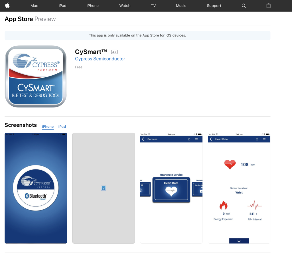
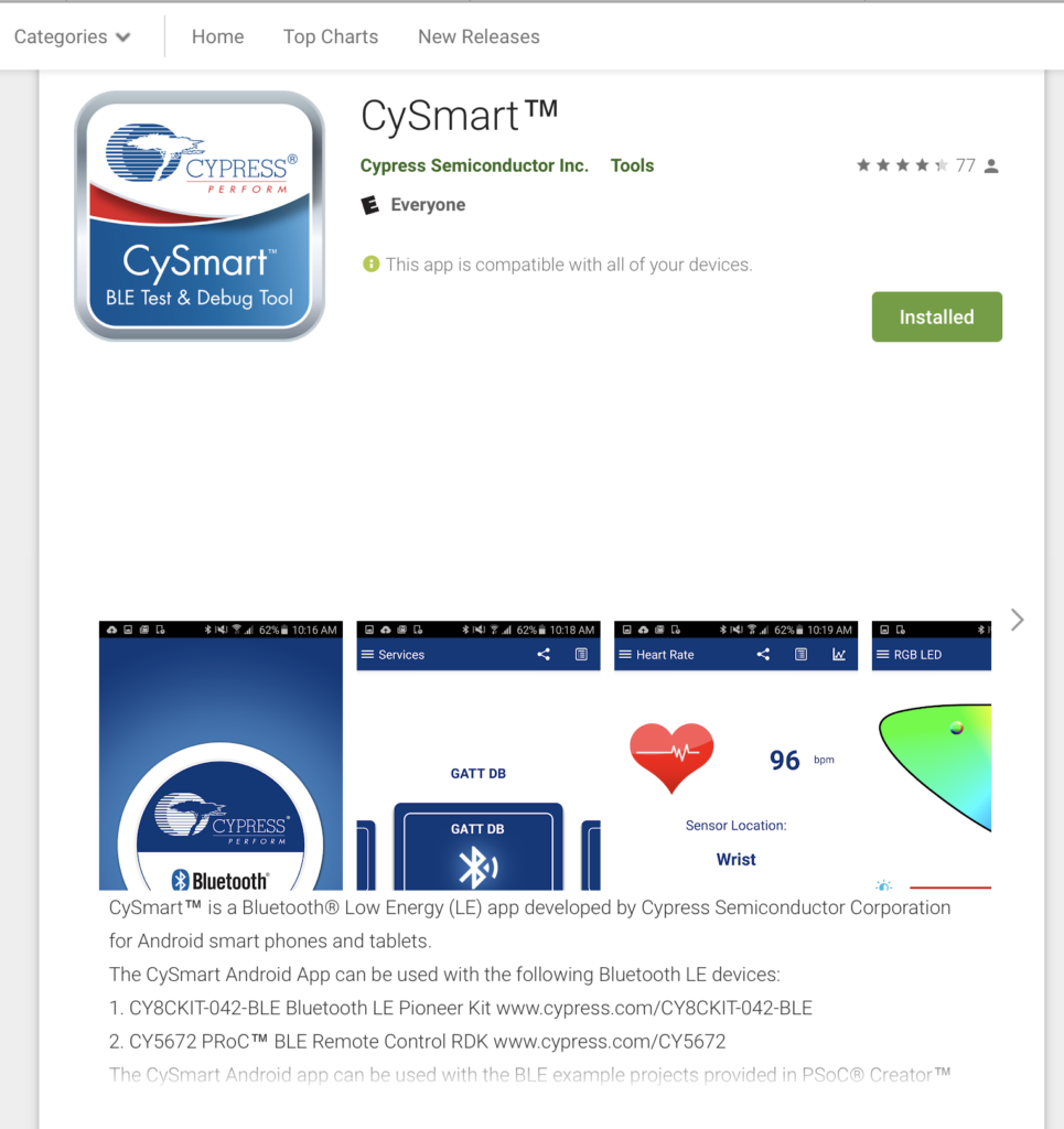
  5. How to run CySmart

The steps that we will follow are:

  1. Run BT Designer
  2. Create a project called L5_BluetoothLED
  3. Go to the characteristics page
  4. Add a vendor specific service
  5. Name the Service L5Service
  6. Add an optional characteristic that is vendor specific
  7. Name it RED
  8. Make it 1 byte with an initial value of 01
  9. Set it up for host write
  10. Add a user description to the characteristic
  11. Generate the code
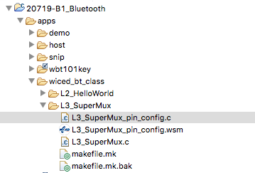
  12. Move the folder to the wiced_bt_class folder
  13. Fix the three include problems
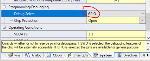
  14. Reset the debug UART to PUART
  15. When there is a write, change the value of the WICED_LED_1 GPIO
  16. Test

BLE Concepts

In the world of BLE there are two sides of every connection

  • The Central – typically a cellphone
  • The Peripheral – your WICED device

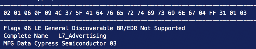
Centrals listen for Peripherals that are Advertising.  Advertising is a periodic packet of up to 31 bytes of information that a Peripheral will send out to make it presence known.  When a Central hears the Advertising packets of a Peripheral that is “interesting” it can initiate a connection.

Once a connection is made, how do you exchange information?  The answer is that a Peripheral has a database running inside of it.  The database is called a “GATT database”.   A Central can perform “Service Discovery” to find all of the legal stuff in the database.  The GATT database is organized into one or more “Services” that have one or more “Characteristics”.  For instance a Heart Rate Monitor might have a “Heart Rate Service” with two characteristics, one for heart rate and one for battery level.

There are two types of Services.  Ones that are specified by the Bluetooth SIG, like heartrate.  And vendor specific custom services.

Run Bluetooth Designer

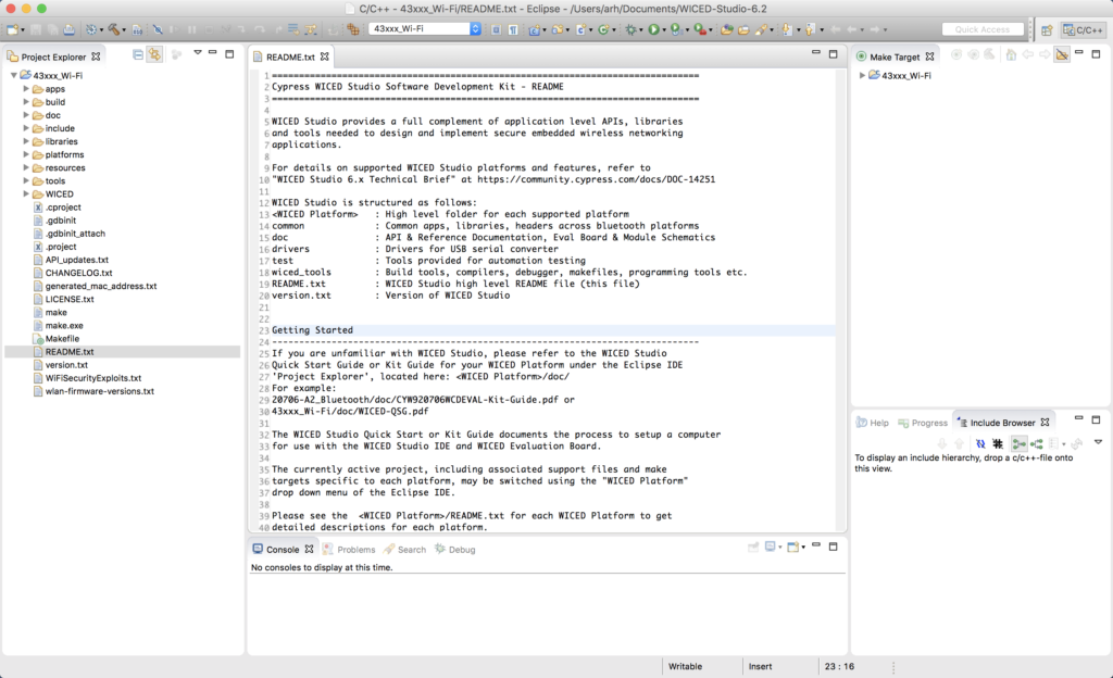
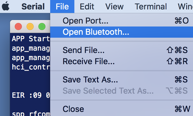
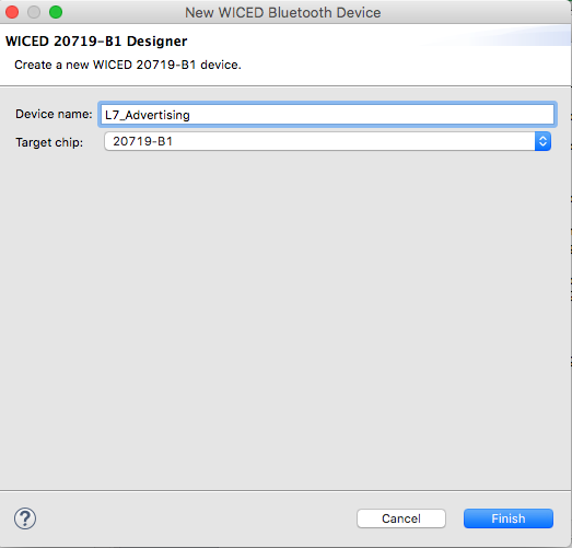
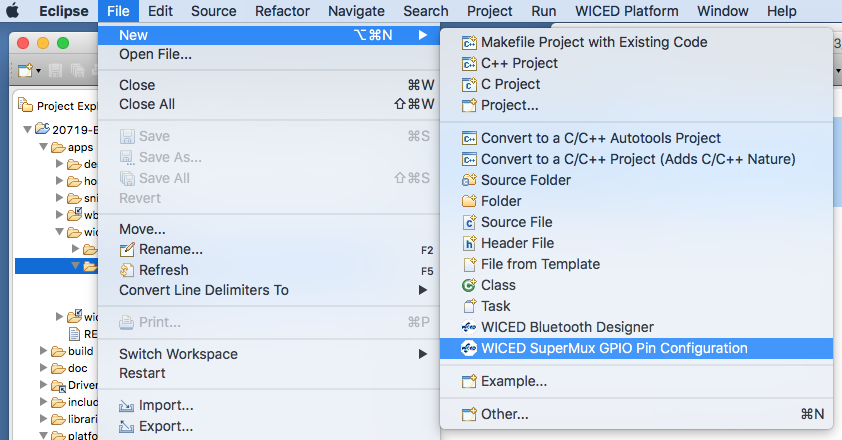
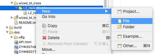
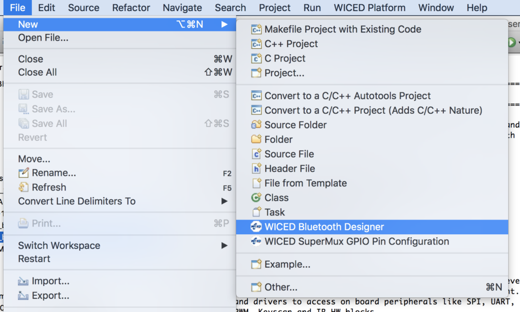
The Bluetooth Designer is a GUI tool that we built into Eclipse.  It allows you to configure some of the fundamental Bluetooth feature (like the GATT Database) and then automatically generate the code.  Start Bluetooth Designer by running File->New->WICED Bluetooth Designer.

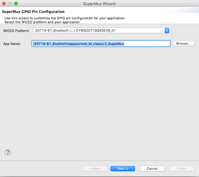
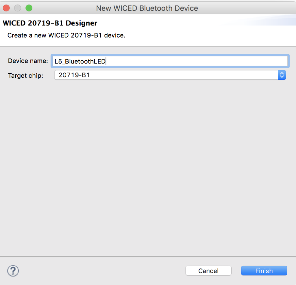
Since this is Lesson 5 and we are going to write and LED… call the project “L5_BluetoothLED”

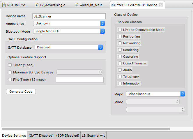
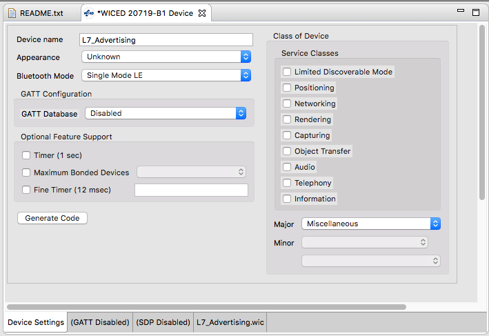
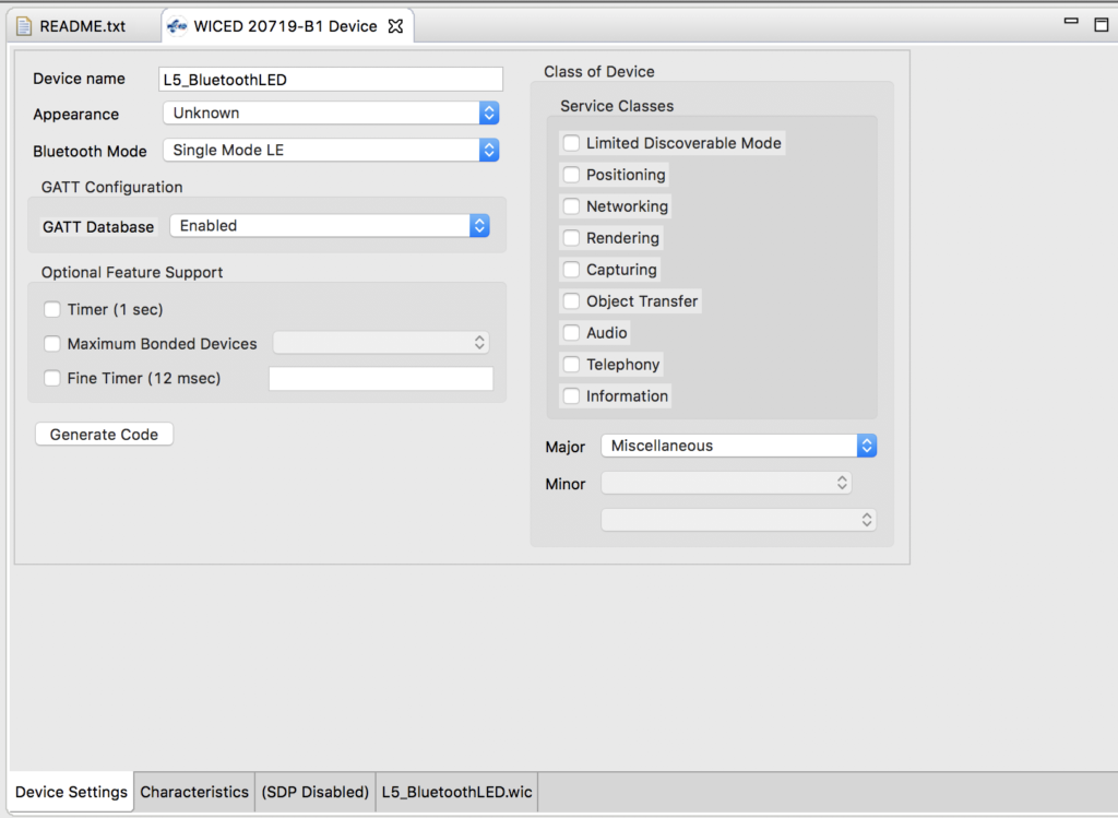
Once you start BT Designer, you screen should look like this.  The project is going to be a BLE only project.

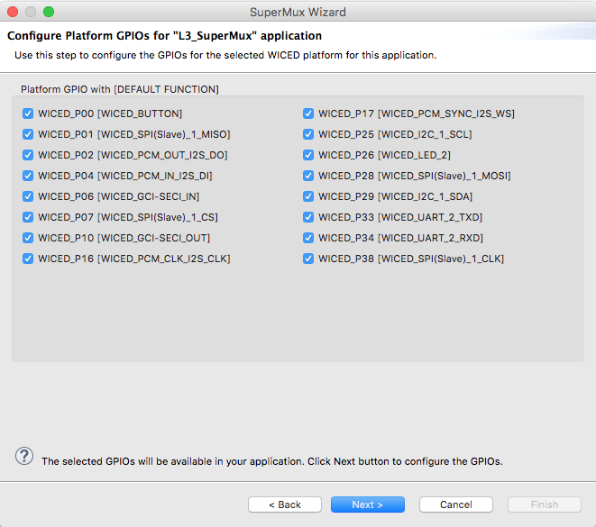
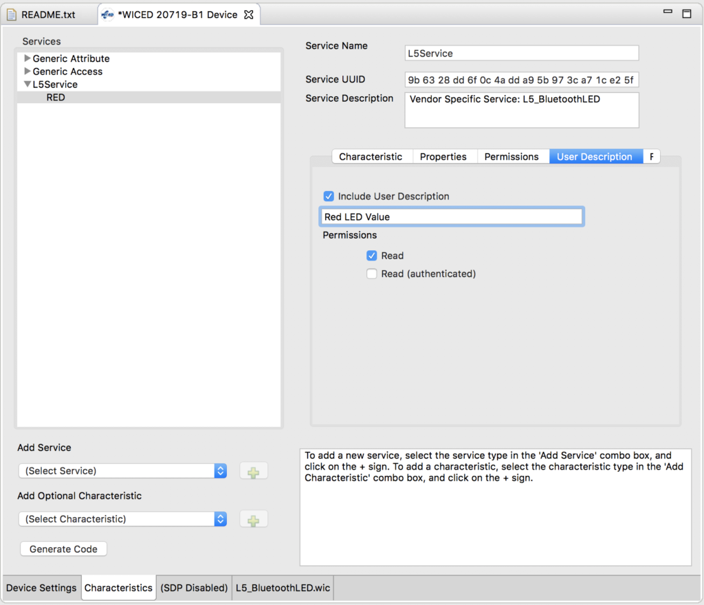
The Characteristics button lets you setup the GATT database.

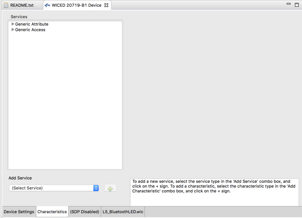
Add a service by selecting vendor specific service and then hitting the “+”

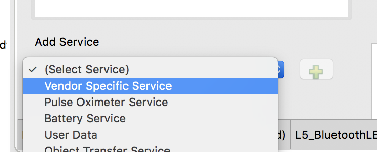
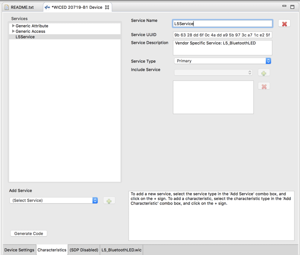
I’ll call the service “L5Service”

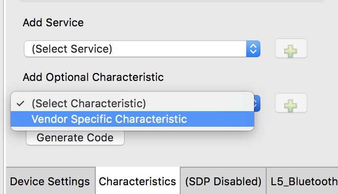
Next add a characteristic by selecting “vendor specific characteristic” and pressing “+”

Change the name to “RED”, Make the device role “Host write to or reads from service”.  Make the size 1 byte and set the initial value to 01 (it must be 01 not 1 or 001)

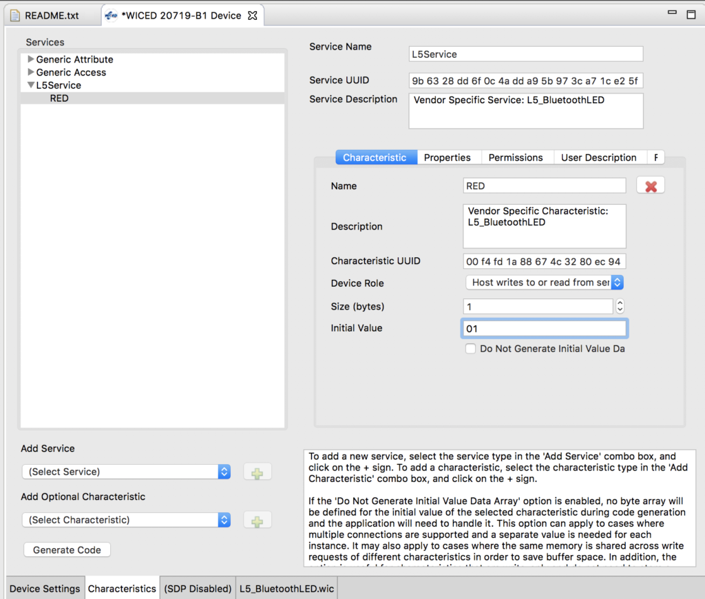
When we are looking at this remotely you would like to be able to see the user description.  So click that tab and give it a description.

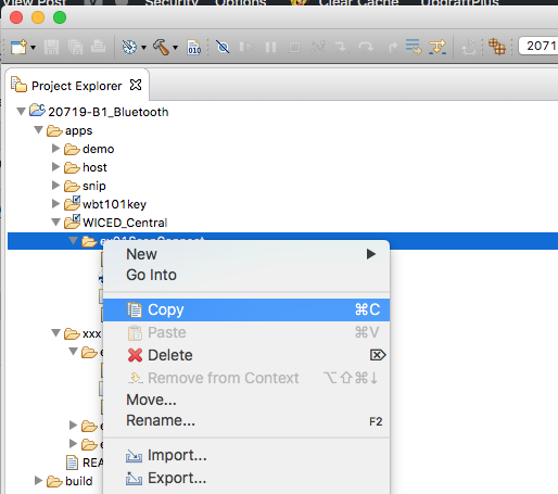
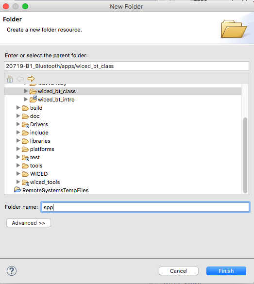
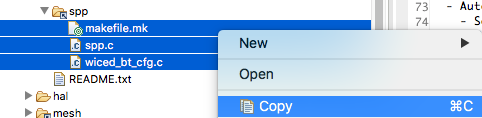
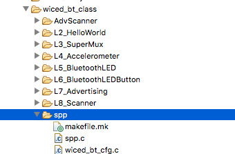
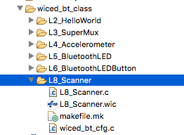
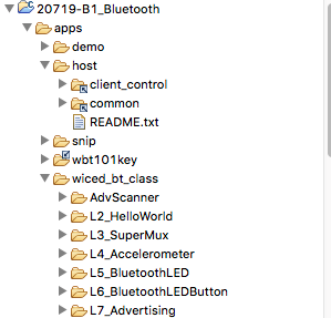
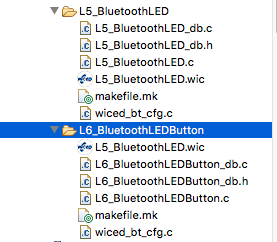
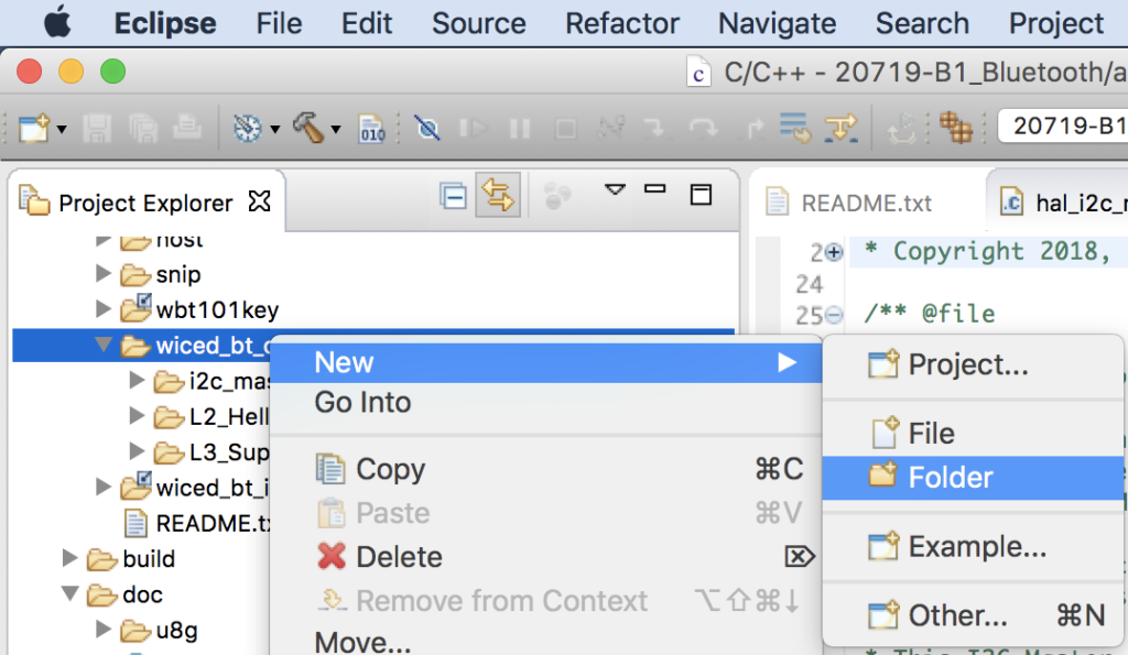
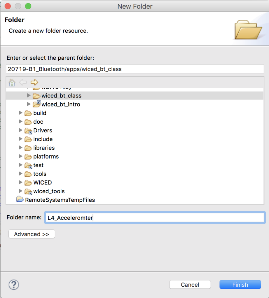
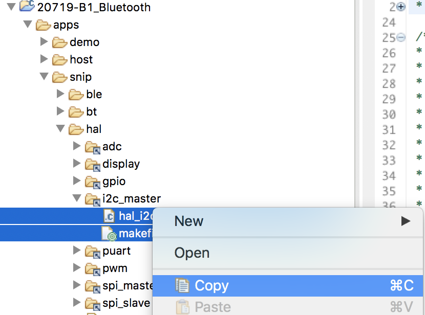
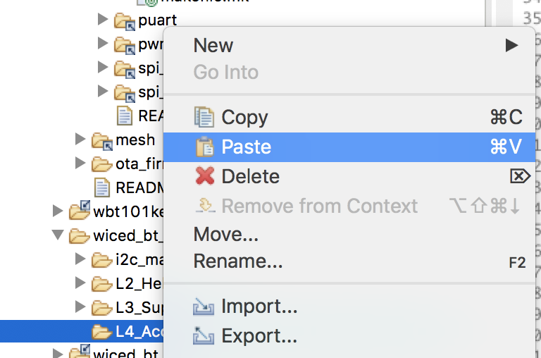
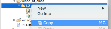
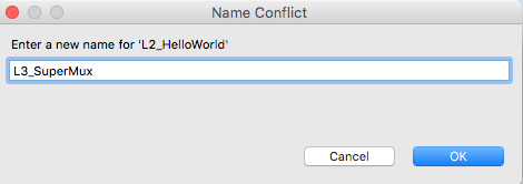
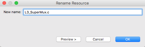
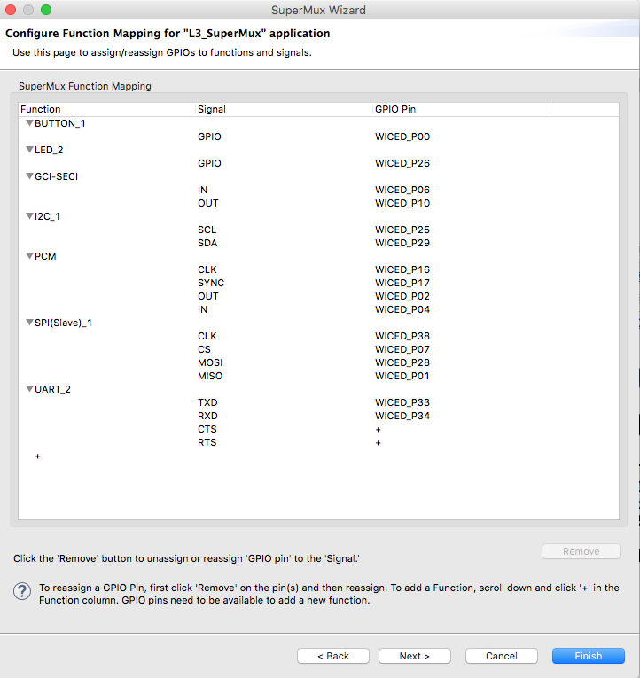
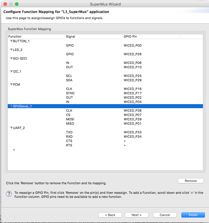
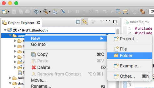
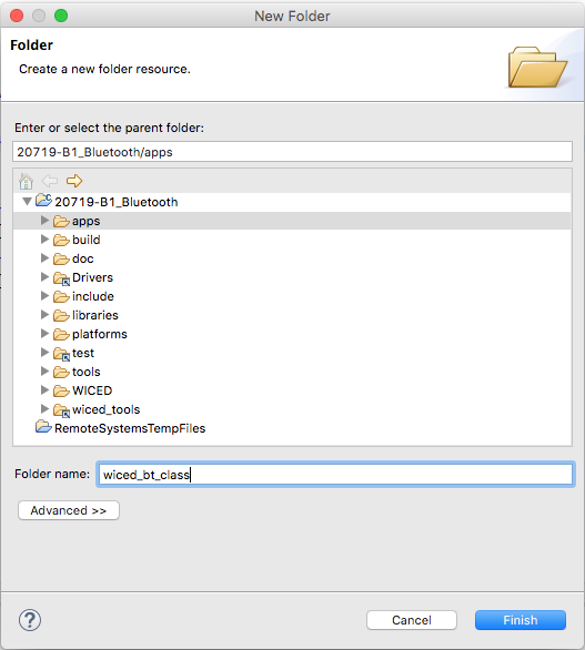
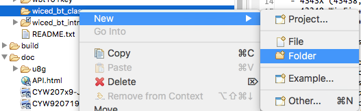
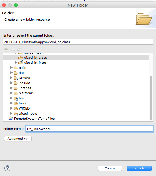
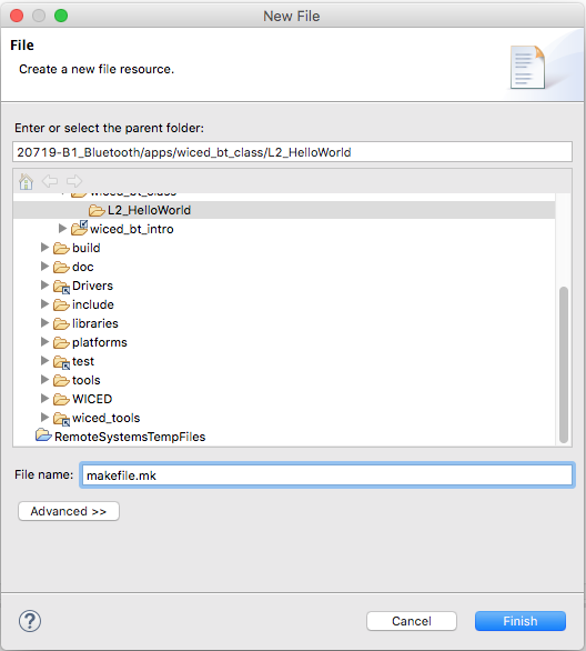
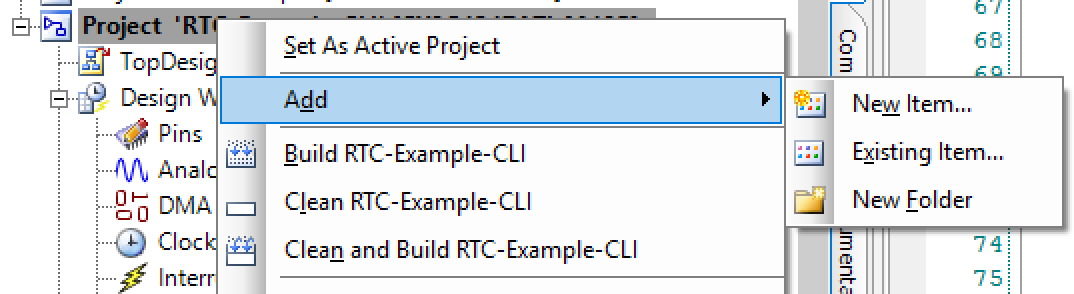
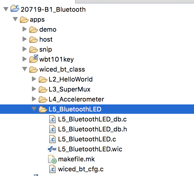
Press Generate Code button.  You will end up with a folder in the top level apps directory.  I don’t like this, so lets move it into our class projects folder.  You can do this by dragging the folder to the wiced_bt_class folder.  Now it should look like this:

Unfortunately, there are three little issues that this creates which need to be fixed.  First, you need to fix L5_BluetoothLED.c as this include is wrong.

#include "../wiced_bt_class/L5_BluetoothLED/L5_BluetoothLED_db.h"

And change it to:

#include "L5_BluetoothLED_db.h"

Next edit L5_BluetoothLED_db.h and add the #include “wiced.h”

#include "wiced.h"

Finally edit the L5_BluetoothLED_db.c to fix the same include problem.

#include "../wiced_bt_class/L5_BluetoothLED/L5_BluetoothLED_db.h"

It should be like this.

#include "L5_BluetoothLED_db.h"

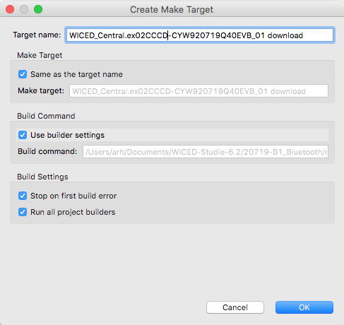
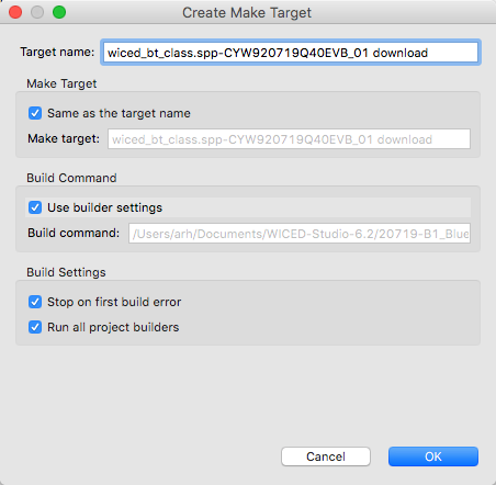
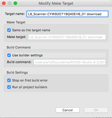
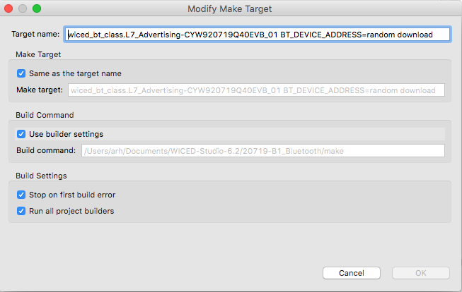
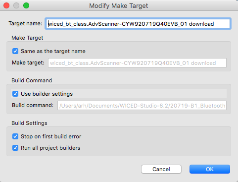
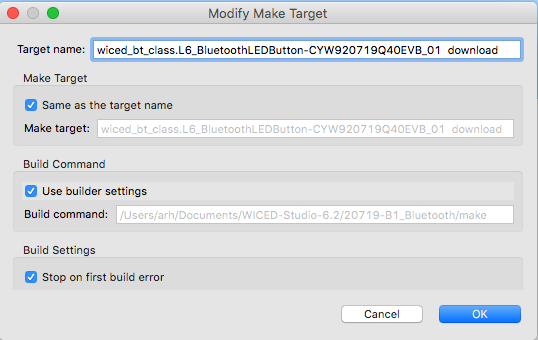
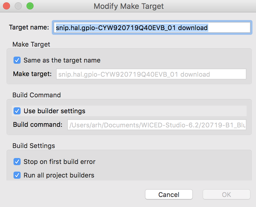
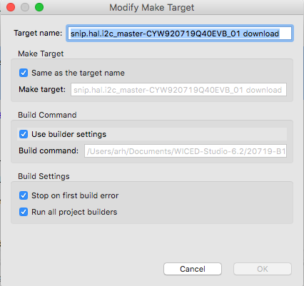
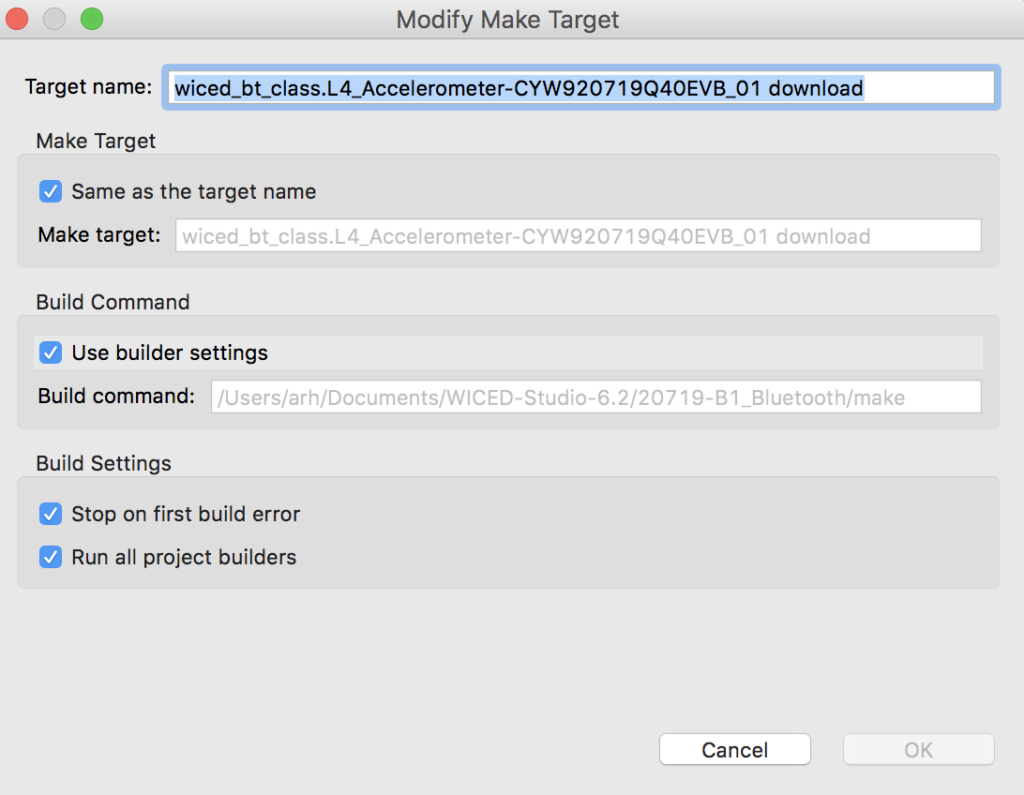
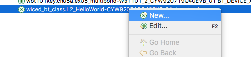
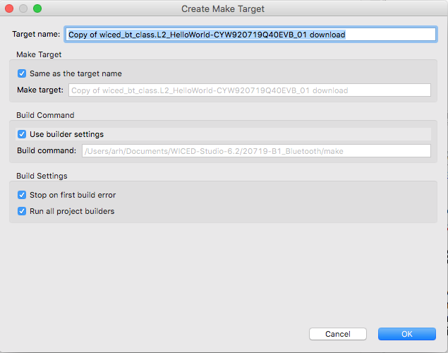
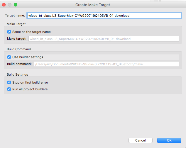
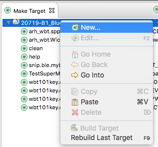
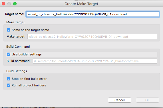
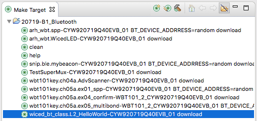
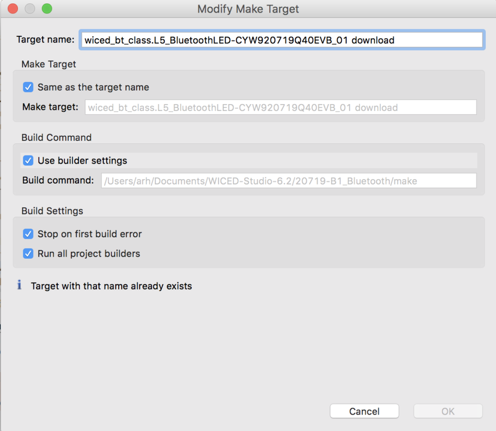
Now edit the make target that was created by the BT Designer and change it to:

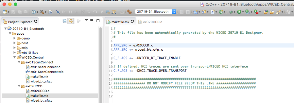
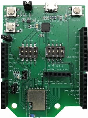
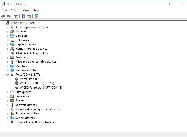
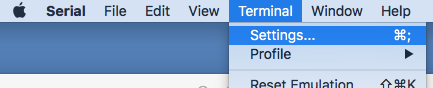
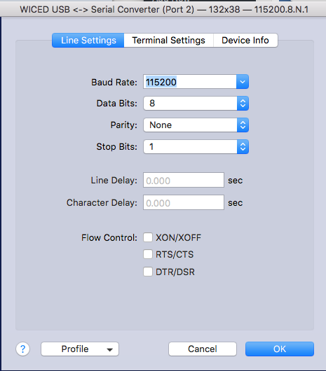
Remember in the earlier lesson I showed you about the WICED HCI UART and the WICED PUART.  Well by default the WICED_BT_TRACE is setup to go to the HCI UART.  So, lets fix the output of BT_TRACE to go to the PUART by changing the file “L5_BluetoothLED.c”

#if ((defined WICED_BT_TRACE_ENABLE) || (defined HCI_TRACE_OVER_TRANSPORT))
/* Set the Debug UART as WICED_ROUTE_DEBUG_NONE to get rid of prints */
//  wiced_set_debug_uart( WICED_ROUTE_DEBUG_NONE );
/* Set Debug UART as WICED_ROUTE_DEBUG_TO_PUART to see debug traces on Peripheral UART (PUART) */
wiced_set_debug_uart( WICED_ROUTE_DEBUG_TO_PUART );
/* Set the Debug UART as WICED_ROUTE_DEBUG_TO_WICED_UART to send debug strings over the WICED debug interface */
//wiced_set_debug_uart( WICED_ROUTE_DEBUG_TO_WICED_UART );
#endif

The last thing that we want to do is fix it so that when the Central writes a new value into the RED LED characteristic we should write the GPIO to the new value.  In L5_BluetoothLED.c make this change.

     case HDLC_L5SERVICE_RED_VALUE:
WICED_BT_TRACE("LED = %d\n",l5_bluetoothled_l5service_red[0]);
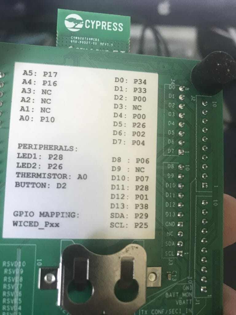
wiced_hal_gpio_set_pin_output(WICED_GPIO_PIN_LED_2,l5_bluetoothled_l5service_red[0]);
break;

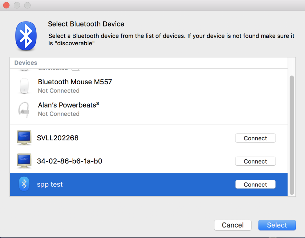
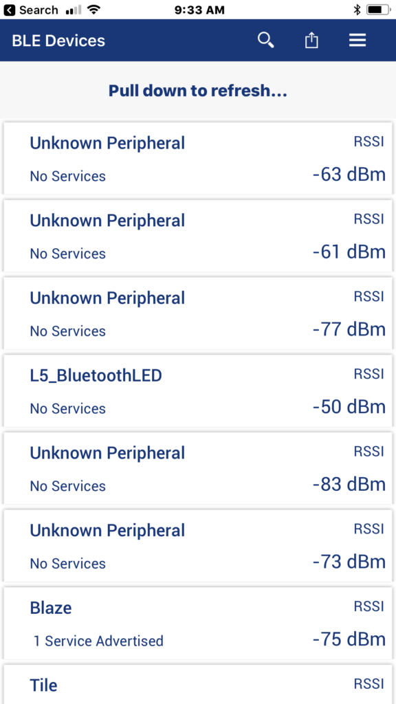
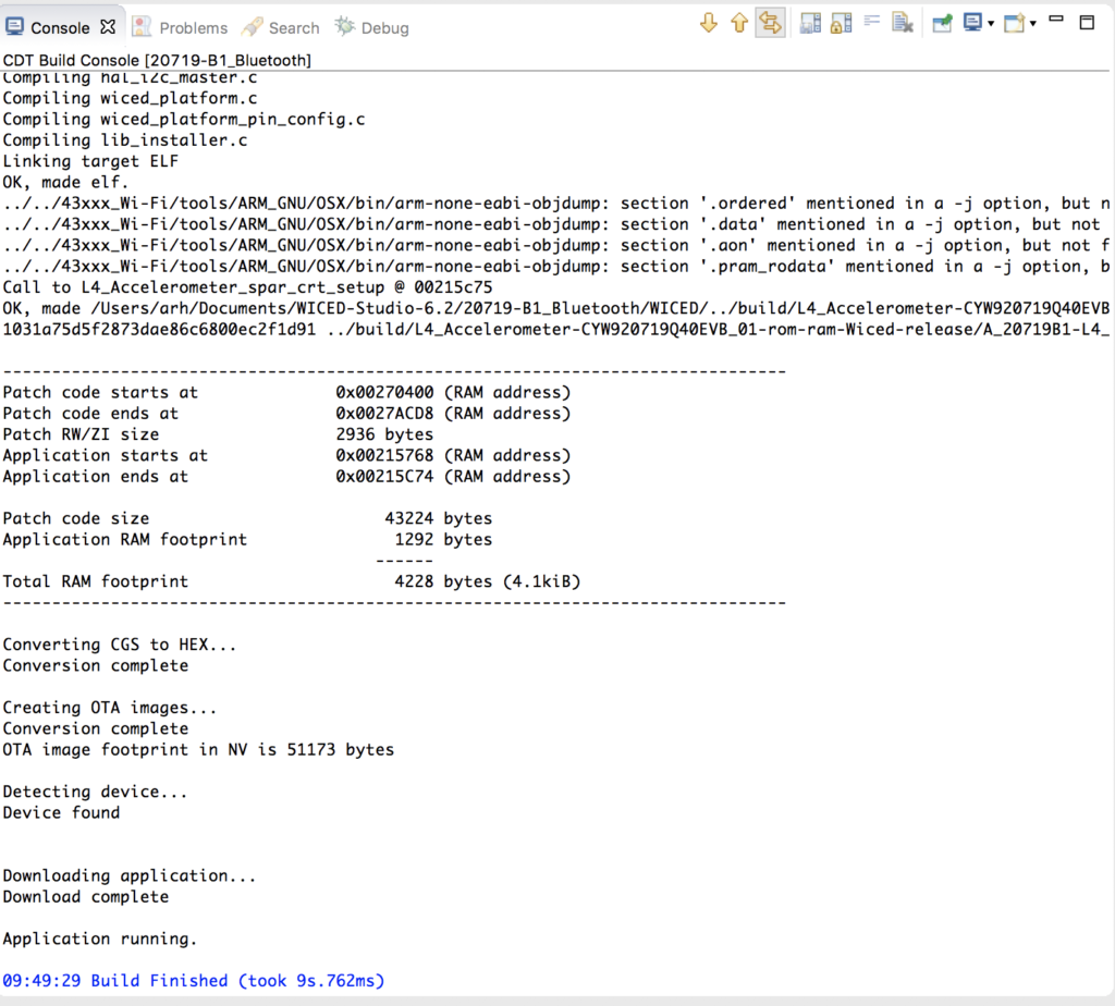
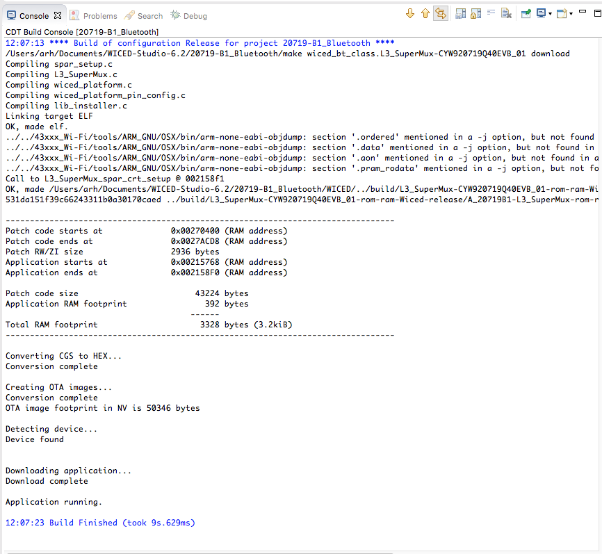
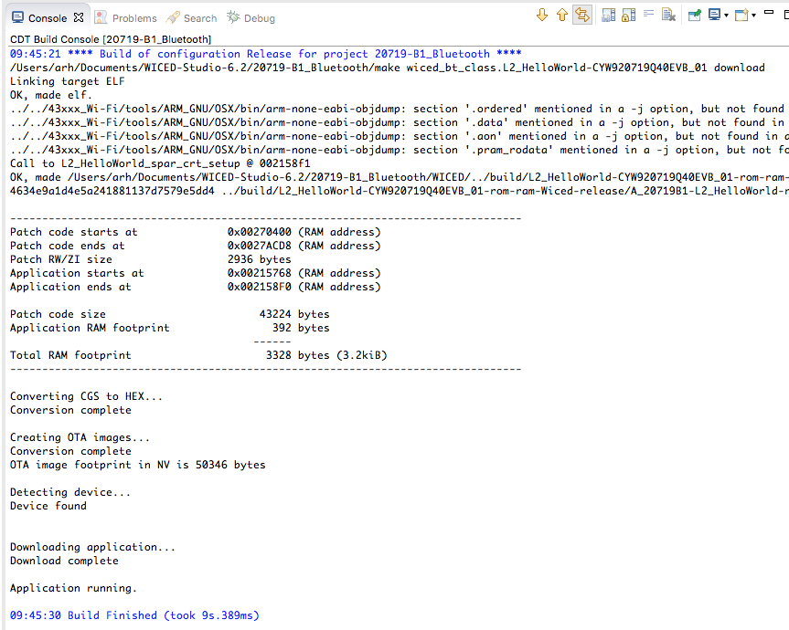
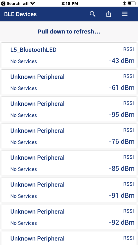
Now build the project and see what happens.  The first testing step will be to open CySmart.  You can see that a device called “L5_BluetoothLED” is advertising.

When I click it, you can see that there is a GattDB.

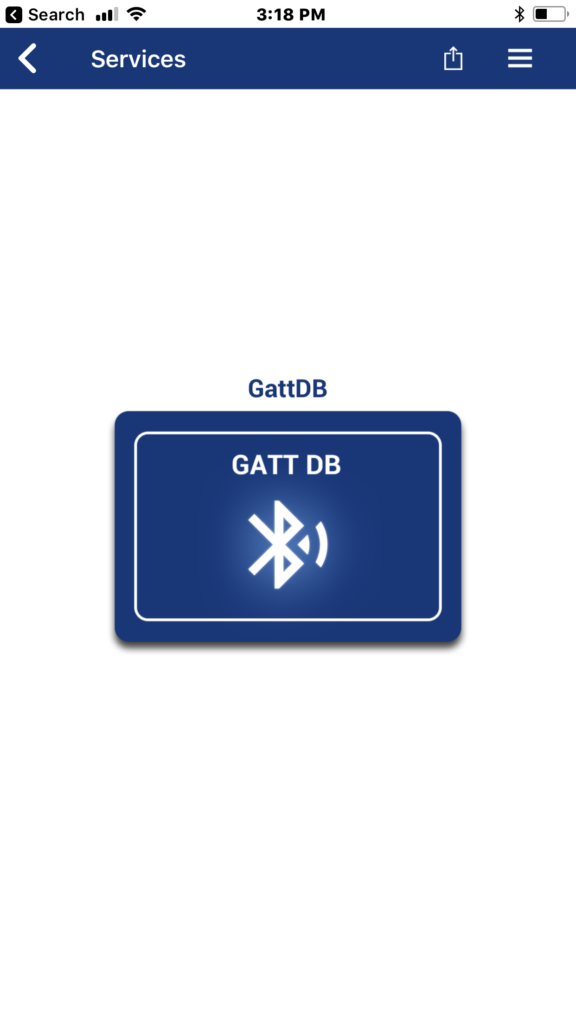
When I click on the database, I can see that there is only one service (which makes sense as we setup only one)

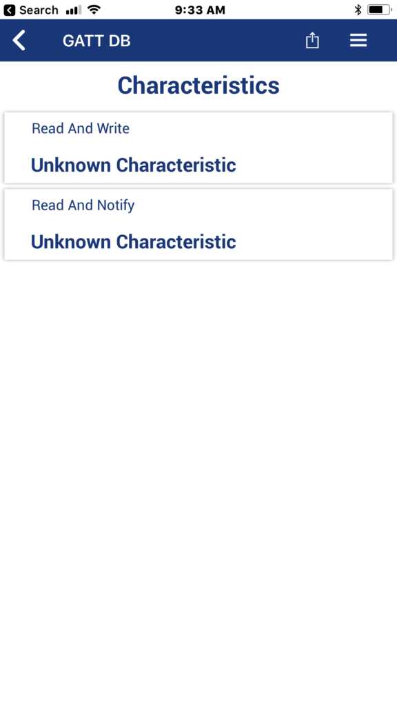
Click on the Service and you can see that there is only one characteristic in the service… and its value is 01.

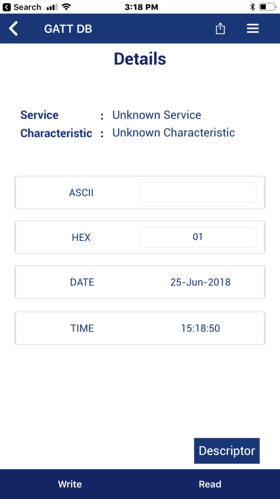
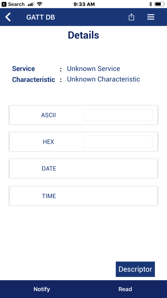
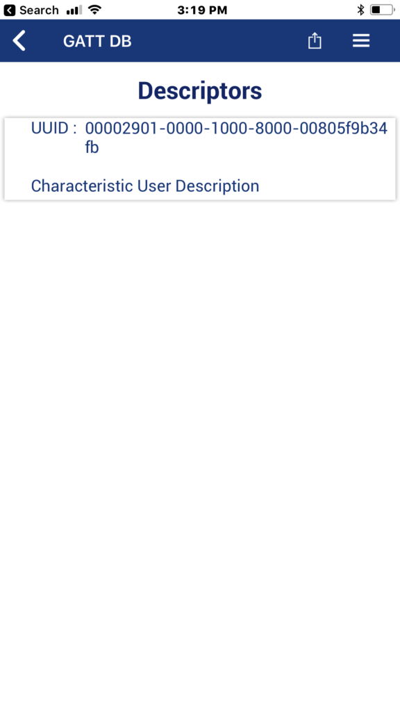
When you click the descriptor button you can see that there is a Characteristic User Description


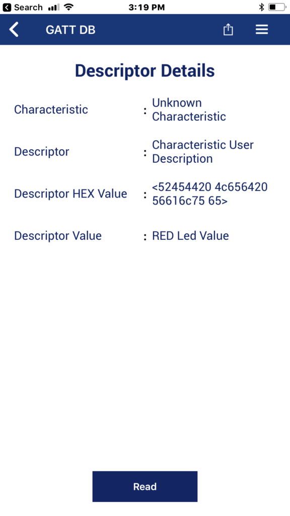
And finally the value is “Red LED Value”.  That is what we setup.

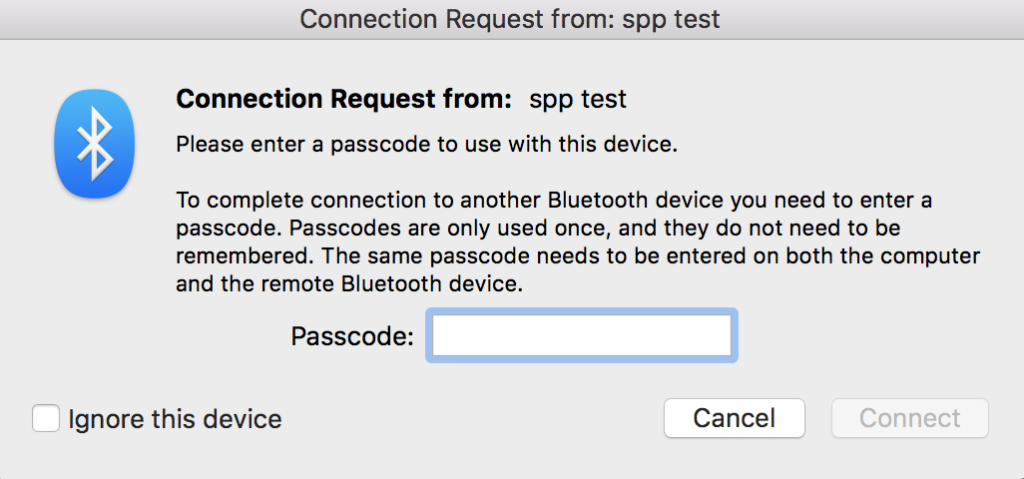
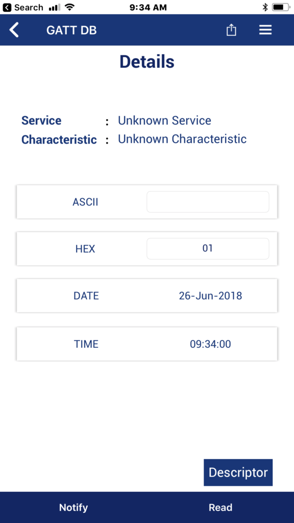
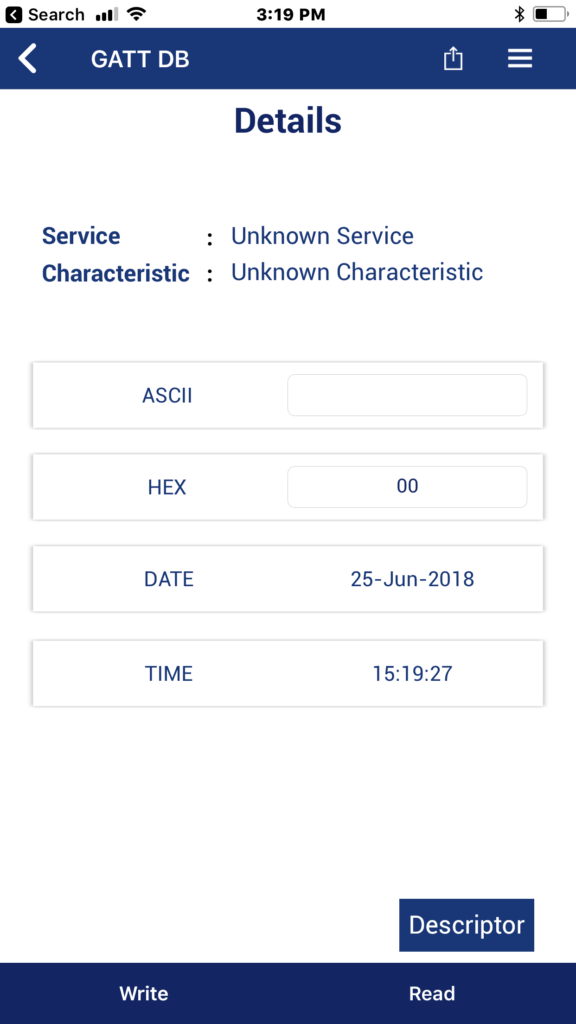
When you click back … then click on the write it will bring up this window where I can send a new value.

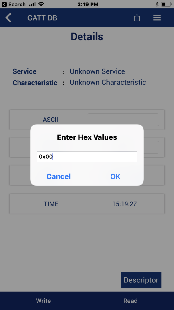
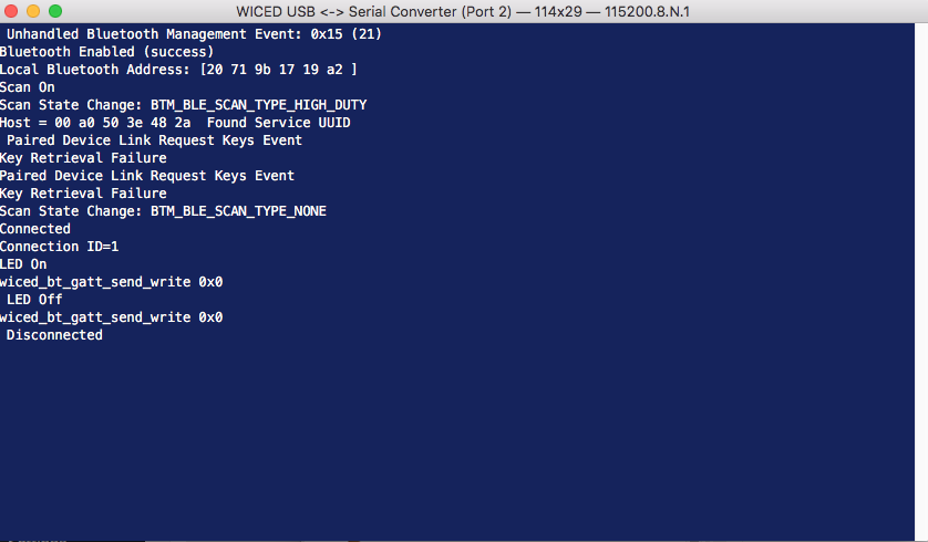
Now the value is 0x00 and the RED LED is on (remember from earlier that it is active low so that makes sense)


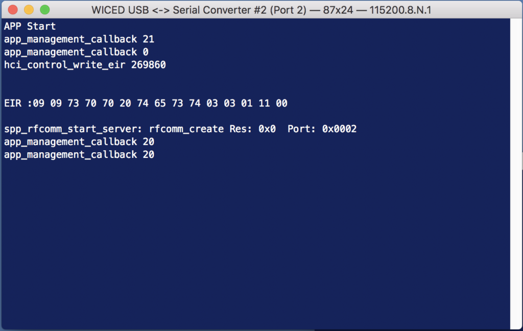
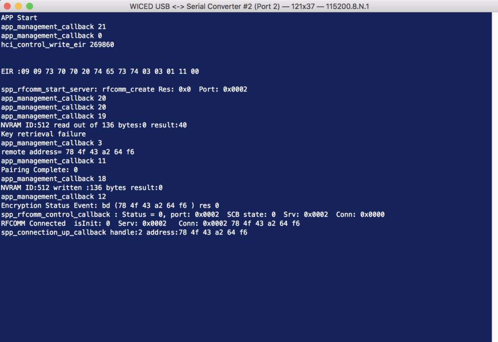
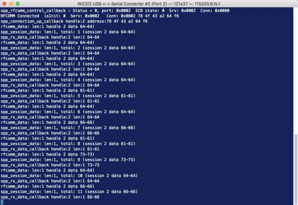
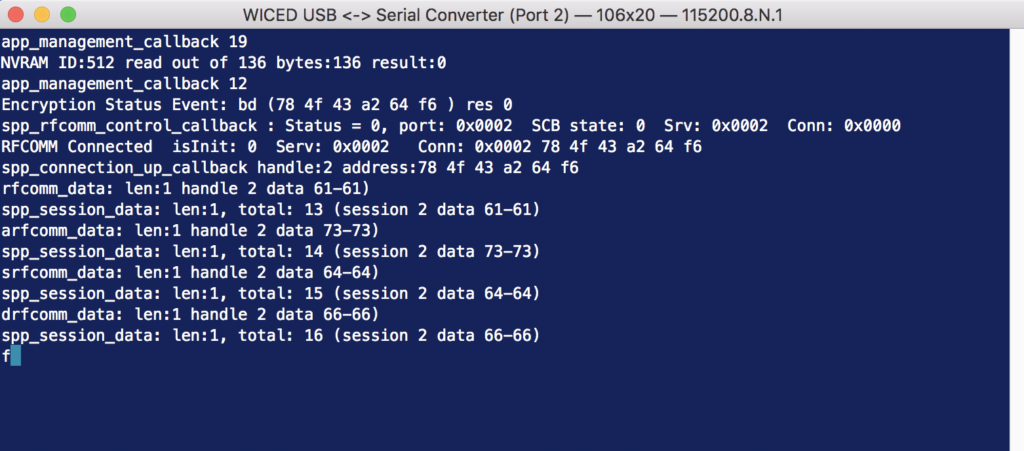
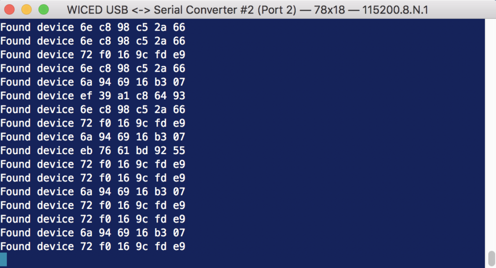
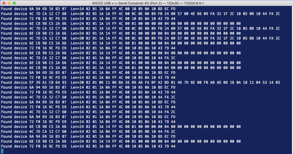
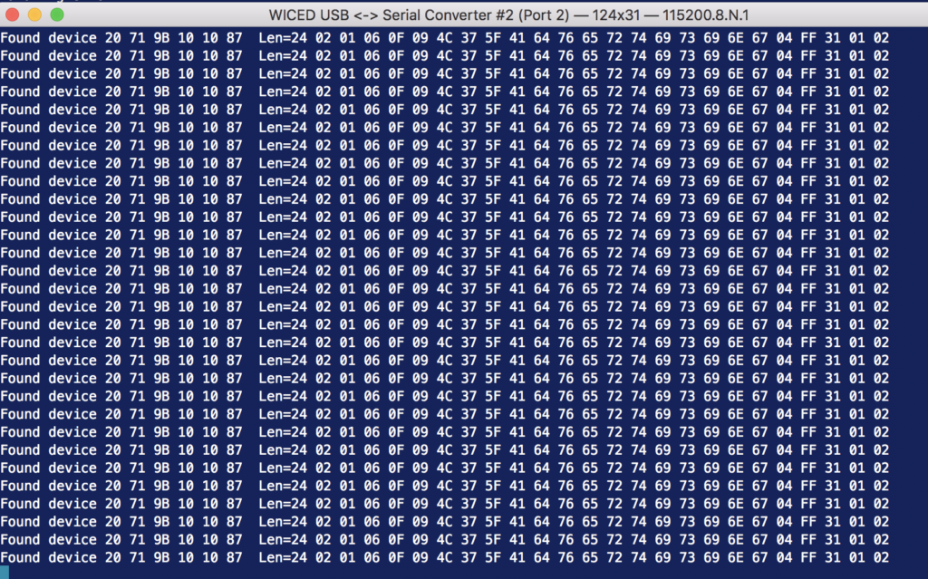
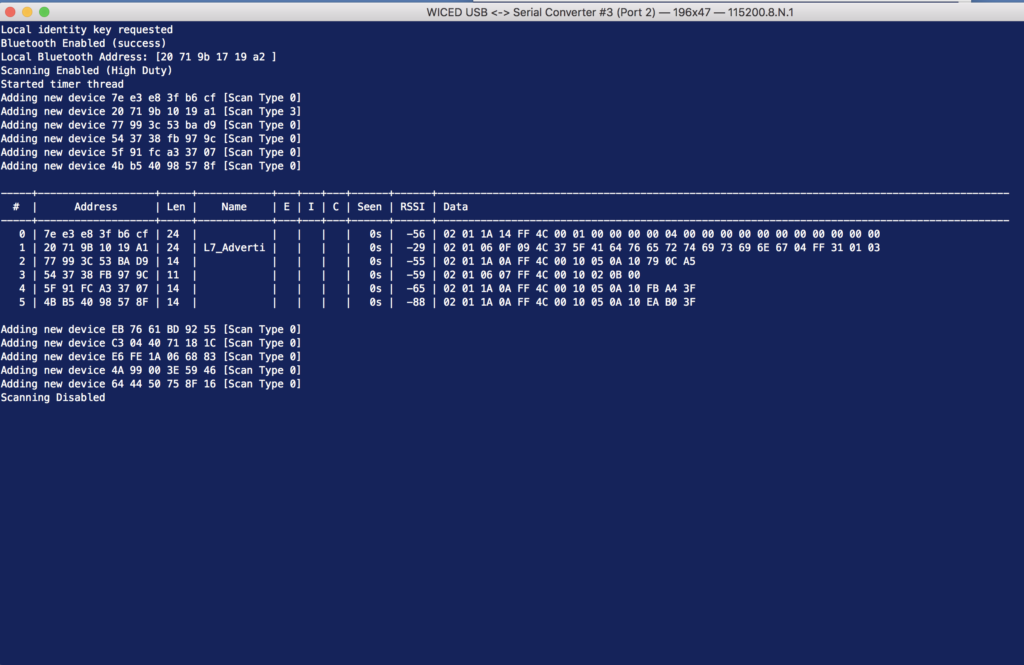
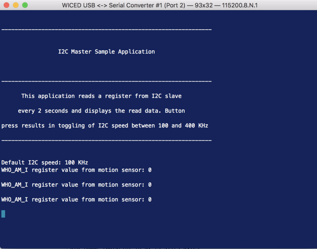
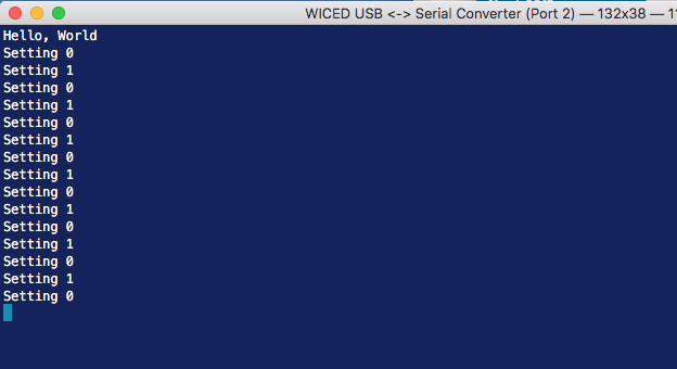
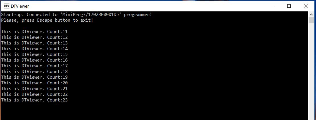
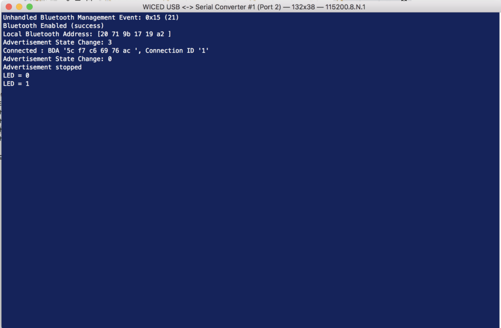
And when I look at the terminal I can see two writes (I wrote again before I took this screen shot)

A Tour of the Source Code

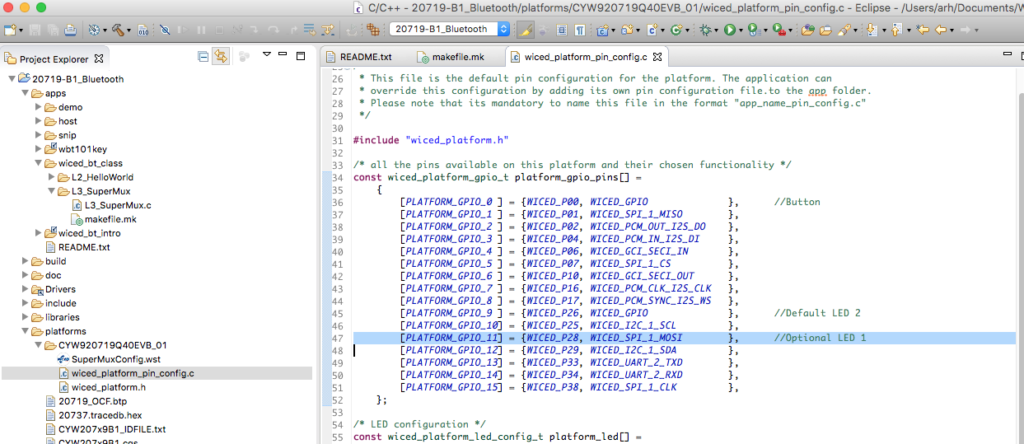
The GATT Database is in the file L5_BluetoothLED_db.c

const uint8_t gatt_database[] = // Define GATT database
{
/* Primary Service 'Generic Attribute' */
PRIMARY_SERVICE_UUID16 (HDLS_GENERIC_ATTRIBUTE, UUID_SERVICE_GATT),
/* Primary Service 'Generic Access' */
PRIMARY_SERVICE_UUID16 (HDLS_GENERIC_ACCESS, UUID_SERVICE_GAP),
/* Characteristic 'Device Name' */
CHARACTERISTIC_UUID16 (HDLC_GENERIC_ACCESS_DEVICE_NAME, HDLC_GENERIC_ACCESS_DEVICE_NAME_VALUE,
UUID_CHARACTERISTIC_DEVICE_NAME, LEGATTDB_CHAR_PROP_READ,
LEGATTDB_PERM_READABLE),
/* Characteristic 'Appearance' */
CHARACTERISTIC_UUID16 (HDLC_GENERIC_ACCESS_APPEARANCE, HDLC_GENERIC_ACCESS_APPEARANCE_VALUE,
UUID_CHARACTERISTIC_APPEARANCE, LEGATTDB_CHAR_PROP_READ,
LEGATTDB_PERM_READABLE),
/* Primary Service 'L5Service' */
PRIMARY_SERVICE_UUID128 (HDLS_L5SERVICE, __UUID_L5SERVICE),
/* Characteristic 'RED' */
CHARACTERISTIC_UUID128_WRITABLE (HDLC_L5SERVICE_RED, HDLC_L5SERVICE_RED_VALUE,
__UUID_L5SERVICE_RED, LEGATTDB_CHAR_PROP_READ | LEGATTDB_CHAR_PROP_WRITE,
LEGATTDB_PERM_READABLE | LEGATTDB_PERM_WRITE_REQ),
/* Descriptor 'Characteristic User Description' */
CHAR_DESCRIPTOR_UUID16 (HDLD_L5SERVICE_RED_USER_DESCRIPTION,
UUID_DESCRIPTOR_CHARACTERISTIC_USER_DESCRIPTION, LEGATTDB_PERM_READABLE),
};

Each row in the Database table has a unique “Handle” that is defined in the L5_BluetoothLED_db.h

#define __UUID_L5SERVICE                      0x30, 0x9d, 0x7f, 0x29, 0x73, 0xca, 0x4f, 0xfd, 0xa5, 0x68, 0x17, 0xd8, 0x90, 0x67, 0x7f, 0x35
#define __UUID_L5SERVICE_RED                  0x29, 0xbf, 0x86, 0xa6, 0xc8, 0x6c, 0x4e, 0xa5, 0xaa, 0x56, 0xbd, 0xac, 0x72, 0x80, 0x93, 0xa9
// ***** Primary Service 'Generic Attribute'
#define HDLS_GENERIC_ATTRIBUTE                0x0001
// ***** Primary Service 'Generic Access'
#define HDLS_GENERIC_ACCESS                   0x0014
// ----- Characteristic 'Device Name'
#define HDLC_GENERIC_ACCESS_DEVICE_NAME       0x0015
#define HDLC_GENERIC_ACCESS_DEVICE_NAME_VALUE 0x0016
// ----- Characteristic 'Appearance'
#define HDLC_GENERIC_ACCESS_APPEARANCE        0x0017
#define HDLC_GENERIC_ACCESS_APPEARANCE_VALUE  0x0018
// ***** Primary Service 'L5Service'
#define HDLS_L5SERVICE                        0x0028
// ----- Characteristic 'RED'
#define HDLC_L5SERVICE_RED                    0x0029
#define HDLC_L5SERVICE_RED_VALUE              0x002A
// ===== Descriptor 'User Description'
#define HDLD_L5SERVICE_RED_USER_DESCRIPTION   0x002B

Each characteristic value is held in one of the uint8_t arrays found in “L5_BluetoothLED.c”

/*******************************************************************
* GATT Initial Value Arrays
******************************************************************/
uint8_t l5_bluetoothled_generic_access_device_name[]     = {'L','5','_','B','l','u','e','t','o','o','t','h','L','E','D'};
uint8_t l5_bluetoothled_generic_access_appearance[]      = {0x00,0x00};
uint8_t l5_bluetoothled_l5service_red[]                  = {0x01};
uint8_t l5_bluetoothled_l5service_red_user_description[] = {'R','E','D',' ','L','e','d',' ','V','a','l','u','e'};
/*******************************************************************
* GATT Lookup Table
******************************************************************/
/* GATT attribute lookup table                                */
/* (attributes externally referenced by GATT server database) */
gatt_db_lookup_table l5_bluetoothled_gatt_db_ext_attr_tbl[] =
{
/* { attribute handle,                  maxlen,                                                 curlen,                                                 attribute data } */
{HDLC_GENERIC_ACCESS_DEVICE_NAME_VALUE, 15,                                                     15,                                                     l5_bluetoothled_generic_access_device_name},
{HDLC_GENERIC_ACCESS_APPEARANCE_VALUE,  2,                                                      2,                                                      l5_bluetoothled_generic_access_appearance},
{HDLC_L5SERVICE_RED_VALUE,              1,                                                      1,                                                      l5_bluetoothled_l5service_red},
{HDLD_L5SERVICE_RED_USER_DESCRIPTION,   sizeof(l5_bluetoothled_l5service_red_user_description), sizeof(l5_bluetoothled_l5service_red_user_description), l5_bluetoothled_l5service_red_user_description},
};


Lesson 4 – WICED Bluetooth: Using Snips

WICED Bluetooth Using the CYW20719

# Title Comment
0 A Two Hour WICED Bluetooth Class WICED Bluetooth Using the CYW20719 in all its glory
1 Resources Links to all of the Cypress WICED information including videos, application notes etc.
2 Your First Project Making Hello World & the Blinky LED
3 The Super Mux Tool Learning about platforms and the Super Mux Tool
4 Snips Using the example projects to learn Bluetooth
5 Bluetooth Designer Using the tool to customize a project and get going fast
6 The CCCD & Notification Writing back to the Central
7 Advertising  Beacon Building a beacon project to advertise your custom information 
8 Scanner Viewing the world around you
9 Bluetooth Classic SPP Using the Serial Port Profile to Transmit Lots of Data

Source code: 

  • git@github.com:iotexpert/wiced_bt_intro.git
  • https://github.com/iotexpert/wiced_bt_intro


Summary

In this lesson I am going to show you how to NOT write all of your own code and still get the job done.  In this lesson we are going to do three things.

  1. Examine & Run the hal_gpio snip
  2. Examine & Run the hal_i2c_master snip
  3. Copy the hal_i2c_master snip and make it “more better”

To modify the hal_i2c_master snip I will

  1. Make a new folder called L4_Accelerometer
  2. Copy the makefile.mk and hal_i2c_master.c into the L4_Accelerometer folder
  3. Create a new make target and make sure that things still work
  4. Look at the LSM9DS1 datasheet
  5. Update the function initialize_app to startup the Accelerometer and speed up the polling
  6. Update the function comboread_cb to read the Acceleration registers and print out the values

Run hal_gpio

If you dont already have a make target for snip.hal.hal_gpio create one and then program the board.

Notice that the light blinking will change speeds if you press the button.  Let’s look at the code that does this:

At the beginning it sets up a timer

        // Initialize timer to control the pin toggle frequency
if (wiced_init_timer(&hal_gpio_app_timer, &hal_gpio_app_timer_cb, 0, WICED_SECONDS_PERIODIC_TIMER) == WICED_SUCCESS)
{
if (wiced_start_timer(&hal_gpio_app_timer, LED_BLINK_FREQ_A_IN_SECONDS) != WICED_SUCCESS)
{
WICED_BT_TRACE("Seconds Timer Error\n");
}
}

The timer calls this function each time the timer expires.

/*
* The function invoked on timeout of app. seconds timer.
*/
void hal_gpio_app_timer_cb(uint32_t arg)
{
static uint32_t wiced_seconds = 0; /* number of seconds elapsed */
uint8_t index = 0;
wiced_seconds++;
if (wiced_seconds & 1)
{
for (index = 0; index < sizeof(output_pin_list); index++)
{
wiced_hal_gpio_set_pin_output(output_pin_list[index], GPIO_PIN_OUTPUT_LOW);
}
}
else
{
for (index = 0; index < sizeof(output_pin_list); index++)
{
wiced_hal_gpio_set_pin_output(output_pin_list[index], GPIO_PIN_OUTPUT_HIGH);
}
}
}

And when the button is pressed all it does is switch back and forth between two different intervals for the timer.  And after the switch it restarts the timer.

/*
* Handle interrupt generated due to change in the GPIO state
*/
void hal_gpio_app_interrrupt_handler(void *data, uint8_t pin)
{
static uint32_t blink_freq = LED_BLINK_FREQ_A_IN_SECONDS;
// toggle LED blink rate upon each button press
if (blink_freq == LED_BLINK_FREQ_A_IN_SECONDS)
{
blink_freq = LED_BLINK_FREQ_B_IN_SECONDS;
}
else
{
blink_freq = LED_BLINK_FREQ_A_IN_SECONDS;
}
if (wiced_stop_timer(&hal_gpio_app_timer) == WICED_SUCCESS)
{
wiced_start_timer(&hal_gpio_app_timer, blink_freq);
}
// clear the interrupt status
wiced_hal_gpio_clear_pin_interrupt_status(pin);
}

Run hal_i2c_master

This CYW920719Q40EVB_01 development kit has an I2C LSM9DS1 accelerometer on it.  And I noticed that when looking around in the snips that the Snip called “hal_i2c_master.c” appears to talk to the chip.  Here is a little section of the comments from the top of the snip

 *
* WICED sample application for I2C Master usage
*
* This application demonstrates how to use I2C driver interface
* to send and receive bytes or a stream of bytes over the I2C hardware as a master.
* The on-board LSM9DS1 motion sensor acts as the I2C slave

So, lets run the snip and see what happens.  If you don’t have a make target… well then make one.

Then make the make target.

It turns out that “0” is a bug in the example project.  And printing out the WHO_AM_I register isnt really very interesting.

Modify the hal_i2c_master.c Create a Better Project

I don’t like making changes inside of the WICED SDK files.  But, I want to fix the bug and printout something more interesting.  So start by creating a new folder in the wiced_bt_class folder

Type in the directory name L4_Accelerometer (notice in the screenshot below I mistyped it)

Select the makefile.mk and the hal_i2c_master.c then right click copy the files.

Then select the L4_Accelerometer folder and pick paste.

Create a make target for the L4_Accelerometer

Build it to make sure it still works.

Now that we have a base to stand-on.  Let’s have a look at the data sheet.  I have used these before and I know that you need to turn on the Accelerometer to give you anything interesting.  Turns out CTRL_REG_6_XL is the control register we need.

The other interesting registers are the actual output of the accelerometer.  That is 0x28 –> 0x2D

Start by modifying the function initialize_app to turn on the accelerometer by writing 0x40 to register 0x20

uint8_t status;
// Turn on Accelerometer - Register 0x20... 2g accelerometer on @ 50hz
uint8_t data[] = {0x20, 0x40};
status = wiced_hal_i2c_write(data,sizeof(data),LSM9DS1_ACC_GYRO_I2C_ADDRESS);

I dont really like printing the values every two seconds so I will modify the timer:

  • Make it a milisecond timer
  • Set it to print every 500ms
if ( WICED_SUCCESS == wiced_init_timer( &seconds_timer, &comboread_cb, 0, WICED_MILLI_SECONDS_PERIODIC_TIMER )) {
if ( WICED_SUCCESS != wiced_start_timer( &seconds_timer, 500 )) {
WICED_BT_TRACE( "Seconds Timer Error\n\r" );
}
}

Here is the whole function initialize_app together

void initialize_app( void )
{
wiced_hal_i2c_init();
uint8_t status;
// Turn on Accelerometer - Register 0x20... 2g accelerometer on @ 50hz
uint8_t data[] = {0x20, 0x40};
status = wiced_hal_i2c_write(data,sizeof(data),LSM9DS1_ACC_GYRO_I2C_ADDRESS);
/* register callback for button available on the platform */
wiced_platform_register_button_callback( WICED_PLATFORM_BUTTON_1, button_cb, NULL, WICED_PLATFORM_BUTTON_RISING_EDGE);
current_speed = wiced_hal_i2c_get_speed();
WICED_BT_TRACE("Default I2C speed: %d KHz\n", (CLK_FREQ/current_speed));
/*Start a timer for POLL_TIMER seconds*/
if ( WICED_SUCCESS == wiced_init_timer( &seconds_timer, &comboread_cb, 0, WICED_MILLI_SECONDS_PERIODIC_TIMER )) {
if ( WICED_SUCCESS != wiced_start_timer( &seconds_timer, 500 )) {
WICED_BT_TRACE( "Seconds Timer Error\n\r" );
}
}
}

Next I need to modify the comboread_cb callback.  It will

  • Setup a structure to hold the three acceleration values (Line 145)
  • Then it will read from the LSM9DS1 (Line 152)
  • Then print them (Line 156)
/******************************************************************************
* This function reads the value from I2C slave and prints it
*****************************************************************************/
void comboread_cb (uint32_t arg)
{
UINT8  status = 0xFF;
UINT8 reg_add = 0x28; // Acceleromter register
typedef struct {
int16_t ax;
int16_t ay;
int16_t az;
} __attribute__((packed)) accel_val_t;
accel_val_t data;
status = wiced_hal_i2c_combined_read((UINT8 *)&reg_add, sizeof(UINT8), (uint8_t *)&data, sizeof(data), LSM9DS1_ACC_GYRO_I2C_ADDRESS);
if(I2CM_SUCCESS == status) {
WICED_BT_TRACE("Ax=%d Ay=%d Az=%d\n",data.ax,data.ay,data.az);
}else if(I2CM_OP_FAILED == status) {
WICED_BT_TRACE("I2C comboread operation failed\r\n");
}else if(I2CM_BUSY == status) {
WICED_BT_TRACE("I2C busy\r\n");
}else{
WICED_BT_TRACE("Unknown status from I2C\r\n");
}
}

Now double click the make target and make sure that everything is working.

Lesson 3 – WICED Bluetooth: The Super Mux Tool

WICED Bluetooth Using the CYW20719

# Title Comment
0 A Two Hour WICED Bluetooth Class WICED Bluetooth Using the CYW20719 in all its glory
1 Resources Links to all of the Cypress WICED information including videos, application notes etc.
2 Your First Project Making Hello World & the Blinky LED
3 The Super Mux Tool Learning about platforms and the Super Mux Tool
4 Snips Using the example projects to learn Bluetooth
5 Bluetooth Designer Using the tool to customize a project and get going fast
6 The CCCD & Notification Writing back to the Central
7 Advertising  Beacon Building a beacon project to advertise your custom information 
8 Scanner Viewing the world around you
9 Bluetooth Classic SPP Using the Serial Port Profile to Transmit Lots of Data

Source code: 

  • git@github.com:iotexpert/wiced_bt_intro.git
  • https://github.com/iotexpert/wiced_bt_intro


Summary

You probably noticed and wondered “Why did he use WICED_LED_2 instead of WICED_LED_1”?  The answer to that question is that by default the CYW920719Q40EVB_01 is setup with WICED_LED_2 enabled as a GPIO and WICED_LED_1 used for another purpose.  But to what purpose?  In this lesson we will answer the questions:

  1. What are the default pins?
  2. How do you use the SuperMux tool?
  3. How do you use a PWM?

To do this we are going to copy the L2_HelloWorld project and add a PWM to drive the Green LED also known as WICED_LED_1.

The steps we are going to follow are

  1. Copy the L2_HelloWorld to start a new project called L3_SuperMux
  2. Rename L2_HelloWorld.c
  3. Fix the makefile.mk for the updated source file
  4. Create a new make target
  5. Program to make sure everything is still working
  6. Look at the platform files for CYW920719Q40EVB_01
  7. Run  the SuperMux Tool
  8. Delete the SPI Slave_1 From the SuperMux
  9. Add an LED to the SuperMux
  10. Configure the LED to P28
  11. Apply the SuperMux configuration
  12. Look at the new files added to the project
  13. Look a the makefile.mk
  14. Look L3_SuperMux_pin_config.c
  15. Update L3_SuperMux.c to have correct includes
  16. Update L3_SuperMux.c to start the clock, pin and PWM
  17. Program the project
  18. Look at the Hardware Abstraction Layer Documentation

Copy L2_HelloWorld –> L3_SuperMux

Instead of starting from a blank project.  Lets make a copy of the L2_HelloWorld project.  If you right click on the L2_HelloWorld folder and select copy

Then click on the “wiced_bt_class” folder and select paste.

WICED Studio will then complain that you already have a directory called “L2_HelloWord” and give you the opportunity to rename it.  Call the new project “L3_SuperMux”

Now you need to rename the L2_HelloWorld.c to be L3_SuperMux.c.  Right click on the L2_HelloWorld.c and select rename

Then give it a new file name… like L3_SuperMux.c

Double click makefile.mk and edit it.  You need to change the comment, and the name of the APP_SRC source file.

#
# Lesson 3 - SuperMux
#
APP_SRC +=  L3_SuperMux.c
C_FLAGS += -DWICED_BT_TRACE_ENABLE

Create a make target for this project by right clicking the L2_HelloWorld Make Target, then selecting “New”

That will make a new target… and it will bring up this dialog box.  Notice that it named the target “Copy of …”

Fix it to be “L3_SuperMux” like this:

You should now have an exact copy of L2_HelloWorld, in the project L3_SuperMux.  Double click the make target and make sure that things are still working.  When you build you should get this.  Don’t forget to “Start the Bootloader” if the programming doesn’t work.

Platform Files

If you look on the back of your CYW920719Q40EVB-01 development kit you will find the exact pin map of this board.  On this picture you can see that LED1 is connected to P28

In WICED Studio, the world “Platform” is just another word for Board Support Package.  Basically all of the configuration required to build the firmware for a specific board.  If you click on platforms you will find a directory for the CYW920719Q40EVB.  All of the default configuration for the pins are located in the file “wiced_platform_pin_config.c”

If you look at this file closely, you will see on line 47 that pin P28 is setup as the MOSI of WICED_SPI_1.  That isnt a GPIO!!!.  And you will see a whole block of code on line 74 that is commented out that COULD   configure P28 as a GPIO.  But that would require modifying our default platform files, which I dont want to do.  Now what?  Simple use the SuperMux tool.

/* all the pins available on this platform and their chosen functionality */
const wiced_platform_gpio_t platform_gpio_pins[] =
{
[PLATFORM_GPIO_0 ] = {WICED_P00, WICED_GPIO              },      //Button
[PLATFORM_GPIO_1 ] = {WICED_P01, WICED_SPI_1_MISO        },
[PLATFORM_GPIO_2 ] = {WICED_P02, WICED_PCM_OUT_I2S_DO    },
[PLATFORM_GPIO_3 ] = {WICED_P04, WICED_PCM_IN_I2S_DI     },
[PLATFORM_GPIO_4 ] = {WICED_P06, WICED_GCI_SECI_IN       },
[PLATFORM_GPIO_5 ] = {WICED_P07, WICED_SPI_1_CS          },
[PLATFORM_GPIO_6 ] = {WICED_P10, WICED_GCI_SECI_OUT      },
[PLATFORM_GPIO_7 ] = {WICED_P16, WICED_PCM_CLK_I2S_CLK   },
[PLATFORM_GPIO_8 ] = {WICED_P17, WICED_PCM_SYNC_I2S_WS   },
[PLATFORM_GPIO_9 ] = {WICED_P26, WICED_GPIO              },      //Default LED 2
[PLATFORM_GPIO_10] = {WICED_P25, WICED_I2C_1_SCL         },
[PLATFORM_GPIO_11] = {WICED_P28, WICED_SPI_1_MOSI        },      //Optional LED 1
[PLATFORM_GPIO_12] = {WICED_P29, WICED_I2C_1_SDA         },
[PLATFORM_GPIO_13] = {WICED_P33, WICED_UART_2_TXD        },
[PLATFORM_GPIO_14] = {WICED_P34, WICED_UART_2_RXD        },
[PLATFORM_GPIO_15] = {WICED_P38, WICED_SPI_1_CLK         },
};
/* LED configuration */
const wiced_platform_led_config_t platform_led[] =
{
[WICED_PLATFORM_LED_2] =
{
.gpio          = (wiced_bt_gpio_numbers_t*)&platform_gpio_pins[PLATFORM_GPIO_9].gpio_pin,
.config        = ( GPIO_OUTPUT_ENABLE | GPIO_PULL_UP ),
.default_state = GPIO_PIN_OUTPUT_HIGH,
},
// We can use either LED1 or SPI1 MOSI, by default we are using WICED_P28 for SPI1 MOSI,
// uncomment the following initialization if WICED_P28 is to be used as an LED and set PIN
// functionality in platform_gpio_pins as WICED_GPIO
//        [WICED_PLATFORM_LED_1] =
//            {
//                .gpio          = (wiced_bt_gpio_numbers_t*)&platform_gpio_pins[PLATFORM_GPIO_11].gpio_pin,
//                .config        = ( GPIO_OUTPUT_ENABLE | GPIO_PULL_UP ),
//                .default_state = GPIO_PIN_OUTPUT_HIGH,
//            }
};

SuperMux Tool

The SuperMux tool is a GUI for setting the default configurations of the Pins on the chip.  Like all capable MCUs, this chip has PWMs, SPIs, UARTs, GPIOs, I2C, ADCs etc.  Each pin on the chip can do a bunch of different functions, but only one at a time.  Each pin has a multiplexor in front of it that selects the function of that pin.  The SuperMux tool helps you setup the multiplexors for each pin on the chip.

To run the SuperMux tool, first click on your project directory (remember L3_SuperMux).  The select File–>New–>WICED SuperMux GPIO Pin Configuration

It will ask you which “App Name” you want it to work on.  Since we clicked on the L3_SuperMux app, it uses that name by default.  Press Next

The SuperMux Wizard will give you the opportunity to select which pins you want to configure.  It also shows you the default configuration of each of the pins.  In this case just press “Next” because we want to configure them all.

Now you will see the functions of the chip and which pins they are assigned to.  Notice that WICED_P28 is assigned as the MOSI of SPI(Slave)_1.  We don’t want that.

Remove the SPI(Slave)_1 by selecting it and then pressing the “Remove” button

Now your screen will look like this.  In order to add a new pin configuration you can press the little “+” at the bottom of the function column.

Next press the little “+” button and select LED.

The select which Pin you want assigned to the LED.  In this case we want WICED_P28

After you press finish you will notice that it adds a several files to your project.  And you notice that it creates a file called “makefile.mk.bak” (which is the backup of the original makefile)

First look at the makefile and notice that it added the “L3_SuperMux_pin_config.c” to the sources and added a CFLAG

#
# Lesson 3 - SuperMux
#
APP_SRC +=  L3_SuperMux.c
C_FLAGS += -DWICED_BT_TRACE_ENABLE
C_FLAGS += -DSMUX_CHIP=$(CHIP)
APP_SRC += L3_SuperMux_pin_config.c

So, what is up with the  L3_SuperMux_pin_config.c.  OH!!! I See, this is just a replacement for the default platform configuration.  Notice that P28 is now a WICED_GPIO and that it is now defined in the LED list.

wiced_platform_gpio_t platform_gpio_pins[]=
{
[PLATFORM_GPIO_0]	= {WICED_P00, WICED_GPIO},
[PLATFORM_GPIO_1]	= {WICED_P02, WICED_PCM_OUT_I2S_DO},
[PLATFORM_GPIO_2]	= {WICED_P04, WICED_PCM_IN_I2S_DI},
[PLATFORM_GPIO_3]	= {WICED_P06, WICED_GCI_SECI_IN},
[PLATFORM_GPIO_4]	= {WICED_P10, WICED_GCI_SECI_OUT},
[PLATFORM_GPIO_5]	= {WICED_P16, WICED_PCM_CLK_I2S_CLK},
[PLATFORM_GPIO_6]	= {WICED_P17, WICED_PCM_SYNC_I2S_WS},
[PLATFORM_GPIO_7]	= {WICED_P25, WICED_I2C_1_SCL},
[PLATFORM_GPIO_8]	= {WICED_P26, WICED_GPIO},
[PLATFORM_GPIO_9]	= {WICED_P28, WICED_GPIO},
[PLATFORM_GPIO_10]	= {WICED_P29, WICED_I2C_1_SDA},
[PLATFORM_GPIO_11]	= {WICED_P33, WICED_UART_2_TXD},
[PLATFORM_GPIO_12]	= {WICED_P34, WICED_UART_2_RXD},
};
const wiced_platform_button_config_t platform_button[WICED_PLATFORM_BUTTON_MAX]=
{
[WICED_PLATFORM_BUTTON_1] =
{
.gpio			= &platform_gpio_pins[PLATFORM_GPIO_0].gpio_pin,
.config			= (GPIO_INPUT_ENABLE | GPIO_PULL_UP),
.default_state	= GPIO_PIN_OUTPUT_LOW,
.button_pressed_value	= GPIO_PIN_OUTPUT_LOW,
},
};
const size_t button_count =  (sizeof(platform_button) / sizeof(wiced_platform_button_config_t));
const wiced_platform_led_config_t platform_led[WICED_PLATFORM_LED_MAX]=
{
[WICED_PLATFORM_LED_1] =
{
.gpio			= &platform_gpio_pins[PLATFORM_GPIO_9].gpio_pin,
.config			= (GPIO_OUTPUT_ENABLE | GPIO_PULL_UP),
.default_state	= GPIO_PIN_OUTPUT_HIGH,
},
[WICED_PLATFORM_LED_2] =
{
.gpio			= &platform_gpio_pins[PLATFORM_GPIO_8].gpio_pin,
.config			= (GPIO_OUTPUT_ENABLE | GPIO_PULL_UP),
.default_state	= GPIO_PIN_OUTPUT_HIGH,
},
};

Now that the pins are configured.  We need to setup the PWM.

Configure the Clock and the PWM

Now I will add a little bit of code to the top of  our L3_SuperMux.c to configure the PWM, Clock and Pin.

First add includes for the ACLK and PWM driver.

#include "wiced_hal_aclk.h"
#include "wiced_hal_pwm.h"

Then startup the Clock, Pin and PWM.

    wiced_hal_aclk_enable(2000, ACLK1, ACLK_FREQ_1_MHZ );
wiced_hal_pwm_configure_pin (WICED_GPIO_PIN_LED_1, PWM1 );
wiced_hal_pwm_start(PWM1, PMU_CLK, 0xFFFF-500, 0xFFFF-999,0);

If you want to turn on the PWM you need to do three things

  1. Turn on a clock to drive it (line 17) sets the clock frequency to 2000hz
  2. Attach the PWM to a Pin (line 18) attaches PWM 1 to the pin
  3. Turn on the PWM which is a 16-bit up-counting PWM.  When the PWM is reset it will go to 0xFFFF-999 (the period)… then it will switch at 0xFFFF-500 (the compare value)

When you program this your Green LED aka WICED_LED_1 is being driven by the PWM.  And your RED LED is being driven by your firmware.

Documentation

All of the hardware blocks on the chip have a set of API functions to help you interface with them.  You can find all of that in the Documentation

Lesson 2 – WICED Bluetooth: Your First Project(s)

WICED Bluetooth Using the CYW20719

# Title Comment
0 A Two Hour WICED Bluetooth Class WICED Bluetooth Using the CYW20719 in all its glory
1 Resources Links to all of the Cypress WICED information including videos, application notes etc.
2 Your First Project Making Hello World & the Blinky LED
3 The Super Mux Tool Learning about platforms and the Super Mux Tool
4 Snips Using the example projects to learn Bluetooth
5 Bluetooth Designer Using the tool to customize a project and get going fast
6 The CCCD & Notification Writing back to the Central
7 Advertising  Beacon Building a beacon project to advertise your custom information 
8 Scanner Viewing the world around you
9 Bluetooth Classic SPP Using the Serial Port Profile to Transmit Lots of Data

Source code: 

  • git@github.com:iotexpert/wiced_bt_intro.git
  • https://github.com/iotexpert/wiced_bt_intro


Summary

For our first project, I am going to stand on the shoulder of giants.  In 1978, Brian Kernighan and Dennis Ritchie published “The C Programming Language”.  Here are pictures of my copy.

Kernighan & Ritchie

The reason you do “Hello, World” is that you want to make sure that your compiler chain, programmer etc are all working correctly with something that is super simple.  The only change that I will make to their classic program is to add the “Blinking LED” which is the embedded developers version of “Hello, World”.

The concepts that I want to show in this lesson are.

  1. How to make a new project – makefile.mk, <appname>.c
  2. How NOT to make a new project
  3. How to create a “Make Target”
  4. CYW920719Q40EVB01 Development Kit
  5. WICED PUART and WICED HCI UART
  6. How to start the bootloader
  7. Where the documentation resides for the WICED 20719 hardware abstraction layer
  8. WICED uses ThreadX RTOS

To make this first project the steps are:

  1. Make a new folder called wiced_bt_class  in the Apps Folder
  2. Make a new folder called L2_HelloWorld in the wiced_bt_intro Folder
  3. Create a new file called L2_HelloWorld.c
  4. Create a new file called makefile.mk
  5. Add the code to print HelloWorld & blink the LED to L2_HelloWorld.c
  6. Add the secret incantation to makefile.mk to build the project
  7. Create a “Make Target”
  8. Connect the development kit to your computer
  9. Attach a serial terminal to the PUART
  10. Run the Make Target to Build and Program

Lets do this!

DO NOT DO File->New Project

I always hate to start with a negative statement… but DO NOT make a file project by doing File->New Project.  This is used for creating a new Eclipse project, not a new WICED Studio project.  In WICED Studio we use the make external build system.  If you do File->New Project all hell is going to break loose.  So don’t do any of the things on this menu:

Hello World & Blinking LED

Now lets get on with making a WICED Studio Project.  First create a new folder to hold the projects for the Class in the “Apps” folder by right-clicking and selecting New->Folder

Give it the name “wiced_bt_class”

Create a folder to hold the first project called L2_HelloWorld

Call the folder L2_HelloWorld

Make a new file called L2_HelloWorld.c by right clicking on the L2_HelloWorld folder and selecting New–>File

Give it the name L2_HelloWorld.c

Make a new file called makefile.mk by right clicking on the L2_HelloWorld directory and selecting New->File

and giving it the name makefile.mk

Add some code to the L2_HelloWorld.c

#include "wiced.h"
#include "sparcommon.h"
#include "wiced_platform.h"
#include "wiced_rtos.h"
#include "wiced_hal_gpio.h"
#include "wiced_bt_trace.h"
APPLICATION_START()
{
wiced_set_debug_uart(WICED_ROUTE_DEBUG_TO_PUART);
WICED_BT_TRACE("Hello, World\n");
while(1)
{
WICED_BT_TRACE("Setting 0\n");
wiced_hal_gpio_set_pin_output(WICED_GPIO_PIN_LED_2,0);
wiced_rtos_delay_milliseconds(500,KEEP_THREAD_ACTIVE );
WICED_BT_TRACE("Setting 1\n");
wiced_hal_gpio_set_pin_output(WICED_GPIO_PIN_LED_2,1);
wiced_rtos_delay_milliseconds(500,KEEP_THREAD_ACTIVE );
}
}

Add the secret incantation to the makefile.mk

#
# Lesson 2 - Hello, World
#
APP_SRC +=  L2_HelloWorld.c
C_FLAGS += -DWICED_BT_TRACE_ENABLE

Create a make target

The make target has a VERY specific format.  It is:

directory.directory.appname-platform download

In our case we have all of our projects in a directory called “wiced_bt_class”.  Then we have a directory called “L2_HelloWorld” which holds the exact project.  And our platform name is “CYW920719Q40EVB_01”

Connect the Development Kit To Your Computer

When you plug in your development kit, it will USB enumerate a TWO serial ports.  One of the serial ports (the first one) is called the “WICED HCI UART”.  The second serial port is called the “WICED Peripheral UART” (this is often abbreviated “PUART”)

One of the key things that the WICED HCI UART is used as is a UART to download new code to the bootloader.

The PUART is used as a general purpose serial port.  When we call this function it causes all of our “WICED_BT_TRACE” outputs to go to the the PUART.

    wiced_set_debug_uart(WICED_ROUTE_DEBUG_TO_PUART);

You can see these two UARTs on a PC by running the device manager.

You can see COM17 is the “WICED HCI UART” and COM18 is the “WICED Peripheral UART”

On my Mac I use the program “Serial” which I downloaded from the App Store.

When I run Serial and then to open a Port

You can see the two UARTs.

In order to see the output I will connect to the port with the settings

  • 115200 Baud
  • 8-n-1 (Data bits, Parity, Stop Bits)

With my PC I typically use Putty (remember it was COM18 from the screen above)

On the Mac program serial you can configure it with Terminal->Settings

Program your Development Kit

In the Make Target window you should see a bunch of “targets”.  You probably have a bunch more targets, which came in your installation of WICED Studio by default, but I deleted a bunch of them so I could just see the ones that I created.

To build and program your project, double click the make target we made before.

When you look in the console you should see something like this:

And when you look at your serial terminal you will see this:

And you should also see the blinking LED!!!

Start the Bootloader

If you get this message there are three posibilites

  1. The kit isn’t plugged in
  2. The driver didn’t install properly
  3. The bootloader wont start

Check the first two… and if that doesnt work then what this means is that the bootloader is not listening on the WICED HCI UART.  In order to fix this you need to press reset and hold down the button called “Recover”.  Then release the reset, then release the recover button.  What does this do?  Simple, when the chip comes out of reset, if the recover button is pressed, the chip starts the bootloader instead of the main application.

Here is a picture of the bottom corner of the board.  The button circled in Green is the “Recover”.  The button in Red is “Reset” and the Blue surrounds the LED circuit.

The two LEDs are labeled LED1 and LED2.  LED2 is the Red one, LED1 is the Green one.  The dip switches circled in Blue connect or disconnect the LEDs from the CYW20719.  In my case you can see (barely) that the switch is set to On.  Both of these LEDs are active LOW (0 turns them on)

The Lost Art of Assembly Language Programming

Cypress introduced it’s first mass market microcontroller in 2001. It used a Cypress designed 8 bit CISC processor running at 24 MHz, with as little as 4 KB Flash and 256 bytes RAM. Wrapped around that was a neat array of programmable analog and digital blocks. This may not sound like much, but with a creative mindset you could get these parts to do amazing things. For instance, I once implemented a complete ultrasonic ranging sensor with full wave analog demodulation in a single PSOC1 as shown below.

PSOC1 Ultrasonic Ranging

With CPU resources at a premium, you had to write tight, efficient code to get the most out of PSOC1. A single C library could consume the entire Flash. Consequently, I wrote a lot of assembly code. That’s not so bad, since I actually enjoy it more than C. There’s a certain elegance to well written, fully commented machine code. In the case of PSOC1, here’s what you had to work with: 5 registers, some RAM and Flash. That’s it. Real Men Write In Assembly.

M8C Architecture


We’ll start with simple machine code instruction to make the CPU do something. You can reference the M8C assembly language user guide here for more details. To get the M8C to execute 2+3=5 we write:

mov A,2       ;Load A with 2
add A,3       ;Add 3 to A. Result=5 is in A

We can get fancy by using variables. Let’s add R=P+Q. Assume P is at RAM location 0x20 and Q is at location 0x21, and R is at 0x22

;Initialize variables
mov [0x20],2  ;Load P with 2
mov [0x21],3  ;Load Q with 3

;Add variables
mov X,[0x20]  ;X <- P
mov A,[0x21]  ;A <- Q
adc [X],A     ;X <- P + Q
mov [0x22],X  ;R <- X

The fun thing about assembly is you can always dream up cool ways of doing things in less operations based on the machine’s instruction set. For example, we can simplify the above code as follows:

;Add variables
mov [0x20],[0x22]   ;R <- P
adc [0x22],[0x21]   ;R <- P + Q

In my experience, a good programmer with expert knowledge of the instruction set and CPU resources can always write better code than a compiler. There’s a certain human creativity that algorithms can’t match.

All that being said, I had not seen a good “machine code 101” tutorial for writing assembly in PSOC Creator on modern ARM M0 processors. So let’s walk through one now. We’ll use a CY8CKIT-145 and blink the LED. It’s just what happens to be laying around on the lab bench. Any PSOC4 kit will do.

CY8CKIT-145-40XX

We’ll start by creating a standard project in PSOC Creator, drop a Digital Output pin on the schematic and call it “LED”

Then open the .CYDWR file and drag pin LED to P2[5], since that’s where it is on the LED board. Yours may be in a different place on whatever board you are using.

Now under “Source Files” in the workspace directory you will delete main.c and replace with main.s

Now right clock on “Source Files”, select “Add New File” and select “GNU ARM Assembly File” in the dialog. Rename the file from GNUArmAssembly01.s to main.s

Your workspace ends up looking like this:

So far, so good. Now open main.s, delete everything if it’s not empty and add the following code. This sets up the IDE for M0 assembly architecture

// ==============================================
// ARM M0 Assembly Tutorial
//
// 01 – Blink LED
// ==============================================
.syntax unified
.text
.thumb

Next we need to include register definitions for the chip we are using. These are all from the PSOC4 Technical Reference Manual (TRM)

// ==============================================
// Includes
// ==============================================
.include “cydevicegnu_trm.inc”

Then we are going to do some .equ statements, same as #define in C. This identifies the Port 2 GPIO data register plus bits for the LED pin in on and off state

// ==============================================
// Defines
// ==============================================
.equ LED_DR,CYREG_GPIO_PRT2_DR          // LED data reg address
.equ LED_PIN,5                          // P2.5
.equ LED_OFF,1<<led_pin                 // 0010 0000
.equ LED_ON,~LED_OFF                    // 1101 1111

Now you add the right syntax to set up main()

// ==============================================
// main
// ==============================================
.global main
.func main, main
.type main, %function
.thumb_func

Finally we add the code for main, which is pretty simple:

main:
ldr r5,=LED_DR      // Load GPIO port addr to r5

loop0:
ldr r6,=LED_ON      // Move led data to r6
str r6,[r5]         // Write r6 data to r5 addr

ldr r0,=0xFFFFFF    // Argument passed in r0
bl CyDelayCycles    // Delay for N cycles

ldr r6,=LED_OFF     // Move led data to r6
str r6,[r5]         // Write r6 data to r5 addr

ldr r0,=0xFFFFFF    // Argument passed in r0
bl CyDelayCycles    // Delay for N cycles

b loop0             // Branch loop0

.endfunc            // End of main
.end                // End of code

One thing to note: The function CyDelayCycles is defined CyBootAsmGnu.s. Any function in assembly gets its arguments passed by the first 4 registers r0,r1,r2 and r3. Before calling the function you simply load r0 with the argument then do a bl (branch with link). This is also why I avoided the first 4 registers when messing with LED data. If you’re interested in doing more with ARM assembly, definitely read the Cortex M0+ Technical Reference Manual. It’s a great primer for the M0+ instruction set.

That’s it. End result is a blinking LED. Cool thing is you can use PSOC Creator with all it’s nice features, but sill access the power of machine code.

You can get the project ZIP file here.

Regards
Darrin Vallis

FreeRTOS Command Line Interface (CLI)

Summary

In a previous article, I gnashed my teeth about my implementation of the FreeRTOS FAT SL.  Specifically, I wasn’t very happy about my command line interface.  What I did was cheap and easy, which sometimes is a good thing, but given that the FreeRTOS Command Line Interface comes as part of the FreeRTOS installation, it sure seemed like that would have been a better way to go.  Now that I have finished the FreeRTOS Command Line Interface implementation, I am not totally in love with how it works.  But, it was worth the time to figure it out. In this article In this article I will make a copy of the PSoC Real Time Clock Project, add the FreeRTOS Command Line Interface and explain how the CLI works.  In the next article I will give the project the ability to set and read the time from the RTC component in the PSoC.

While I was working on the implementation I discovered that the example code used FreeRTOS_write and FreeRTOS_read which depend on a Peripheral Driver Library (don’t confuse that with the Cypress Peripheral Driver Library) and are part of FreeRTOS+IO.  I did very a very simple implementation of those commands to make the FreeRTOS Command Line Interface work, and I will talk more about the FreeRTOS+IO in a future article.

FreeRTOS Command Line Interface

The FreeRTOS Command Line Interface is pretty straightforward to use.  Basically you:

  1. Integrate FreeRTOS_CLI.h and .c into your project
  2. Create one or more command functions and register them for use by the CLI by calling FreeRTOS_CLIRegisterCommand
  3. Read input from the terminal UART into a buffer
  4. Call the CLI (when the users presses enter) and display the output

Integrate FreeRTOS Command Line Interface C Files

I start this whole thing by copying the project “RTC-Example” from the previous article into a new project called “RTC-Example-CLI”.  Inside of the directory FreeRTOSv9.0.0/FreeRTOS-Plus/Source/FreeRTOS-Plus-CLI you will find FreeRTOS_CLI.h and FreeRTOS_CLI.c.  These two files have all of the FreeRTOS Command Line implementation.  To make this work I copied them into my project, and then did “Add –> Existing Item” to get PSoC Creator to make them part of the project.

Integrate FreeRTOS Command Line Interface C Files

Create a Command

To use the FreeRTOS Command Line Interface you need to create one or more functions which the CLI will then callback when it detects that the user has typed that command.   Each command takes three input parameters

  1. A pointer to a character buffer where the command can store text to be printed on the screen
  2. The size of that buffer
  3. A pointer to a character buffer that holds the whole string that the user typed

The function is then responsible for

  1. Doing the command
  2. Writing some output into the output buffer (up to the length of the buffer)
  3. Returning pdFALSE (if the command has completed writing the output) or pdTRUE (if it needs to do some more processing or more output)

For example if you want to create a command to clear the screen you would create a function called “clearCommand”  That command would

  1. Ignore the pcCommandString (there are no parameters)
  2. Keep track of the number of characters written into the buffer using a static int
  3. Copy the VT100 Clear String (AKA “\033[2J\033[H”) into the output buffer
  4. Null terminate the output string
  5. If you wrote less characters than the string then return pdTrue
  6. Otherwise return false
/*****************************************************************************\
* Function:    clearCommand
* Input:       char *pcWriteBufer,size_t xWriteBufferLen,const char *pcCommandString
* Returns:     BaseType_t
* Description: 
*     This function clears the screen. It is run by the CLI interpreter
\*****************************************************************************/
BaseType_t clearCommand( char *pcWriteBuffer,size_t xWriteBufferLen, const char *pcCommandString )
{
(void)pcCommandString;
static int processed = 0;
char *clearScreen = VT100_CLEARSCREEN;
// Only allowed to write up top xWriteBufferLen bytes ... 
strncpy(pcWriteBuffer,&clearScreen[processed],xWriteBufferLen-1);
pcWriteBuffer[xWriteBufferLen-1]=0;
processed = processed + xWriteBufferLen-1;
if(processed < (int)strlen(clearScreen))
return pdTRUE;
processed = 0;
return pdFALSE;
}

Once you have created the command function you then need to register it with the FreeRTOS Command Line Interface.  To do that you create a structure of type “CLI_Command_Definition_t” which has 4 members.

  1. The ascii string which the user can type to trigger the command
  2. The help message
  3. A function pointer to the command function
  4. The number of arguments that the CLI should accept
    static const CLI_Command_Definition_t clearCommandStruct =
{
"clear",
"clear: Clear Screen by sending VT100 Escape Code\n",
clearCommand,
0
};

Finally you need to register the command.  You should be aware that this function uses malloc.

FreeRTOS_CLIRegisterCommand( &clearCommandStruct );

Call the CLI and Display

On the FreeRTOS Command Line Interface webpage they provided a sample task to handle the command line interpreter.  I copied this task into my project and then made a few little changes.

  1. My Mac sends a ‘\r’ when you press the return key so I changed line 164 to reflect that
  2. My Mac sends 0x7F when you press the “Delete” key.  So I changed the ‘\b’ (aka backspace) to be 0x7F aka “del”
  3. I fixed the stupid ‘\r\n’ stuff

One of the great annoyances in the world is the way that line breaks in text files and terminals are handled.  It is typical in “unix” to use just a newline “\n”.  However, in “DOS” it is typical to use a carriage return/newline “\r\n”.  All over FreeRTOS it uses DOS mode.  I typically like to use unix mode… so you will find that I made that changes in the FreeRTOS CLI code.

The cliTask function does a number of things.

  1. Initializes the IO System, RTC and Command Line Interface (lines 154-163)
  2. Gets 1 character from the UART using FreeRTOS_read
  3. If the character is a carriage return (\r) then it calls the CLI until there is no more output (lines 167-196).   Remember that when you implement a command function for the CLI, if you return pdFALSE it means that you have no more output, and if you return pdTRUE then you have more output.
  4. If the character is the delete key (0x7F) then erase the character from the input buffer)
  5. Otherwise add it to the input buffer… assuming that you still have room.  (lines 227-232)
/*****************************************************************************\
* Function:    cliTask
* Input:       void *arg  ... unused
* Returns:     void
* Description: 
*     This function is the inifite loop for the command line intepreter.. it
*     reads characters using the FreeRTOS_read function then sends them to the
*     cli when there is a \r 
\*****************************************************************************/
void cliTask(void *arg)
{
(void)arg;
char pcOutputString[ MAX_OUTPUT_LENGTH ], pcInputString[ MAX_INPUT_LENGTH ];
int8_t cRxedChar, cInputIndex = 0;
BaseType_t xMoreDataToFollow;    
FreeRTOS_open( (const int8_t *)"/uart",0 );
clearScreen();
#define INTRO_STRING "Command Line & RTC Demo\n"
FreeRTOS_write(0,INTRO_STRING,strlen(INTRO_STRING));
RTC_Start();
FreeRTOS_CLIRegisterCommand( &clearCommandStruct );	
FreeRTOS_CLIRegisterCommand( &setTimeCommandStruct );	
FreeRTOS_CLIRegisterCommand( &timeCommandStruct );	
while(1)
{
FreeRTOS_read( 0, &cRxedChar, sizeof( cRxedChar ) );
if( cRxedChar == '\r' )
{
/* A newline character was received, so the input command string is
complete and can be processed.  Transmit a line separator, just to
make the output easier to read. */
FreeRTOS_write(0,&cRxedChar,1);
/* The command interpreter is called repeatedly until it returns
pdFALSE.  See the "Implementing a command" documentation for an
exaplanation of why this is. */
do
{
/* Send the command string to the command interpreter.  Any
output generated by the command interpreter will be placed in the
pcOutputString buffer. */
xMoreDataToFollow = FreeRTOS_CLIProcessCommand
(
pcInputString,   /* The command string.*/
pcOutputString,  /* The output buffer. */
MAX_OUTPUT_LENGTH/* The size of the output buffer. */
);
/* Write the output generated by the command interpreter to the
console. */
FreeRTOS_write( 0, pcOutputString, strlen( pcOutputString ) );
} while( xMoreDataToFollow != pdFALSE );
/* All the strings generated by the input command have been sent.
Processing of the command is complete.  Clear the input string ready
to receive the next command. */
cInputIndex = 0;
memset( pcInputString, 0x00, MAX_INPUT_LENGTH );
}
else
{
/* The if() clause performs the processing after a newline character
is received.  This else clause performs the processing if any other
character is received. */
if( cRxedChar == 127 ) // delete character
{
FreeRTOS_write(0,&cRxedChar,1);
/* Backspace was pressed.  Erase the last character in the input
buffer - if there are any. */
if( cInputIndex > 0 )
{
cInputIndex--;
pcInputString[ cInputIndex ] = '\0';
}
}
else
{
/* A character was entered.  It was not a new line, backspace
or carriage return, so it is accepted as part of the input and
placed into the input buffer.  When a \n is entered the complete
string will be passed to the command interpreter. */
if( cInputIndex < MAX_INPUT_LENGTH )
{
FreeRTOS_write(0,&cRxedChar,1);
pcInputString[ cInputIndex ] = cRxedChar;
cInputIndex++;
}
}
}
}
}

As always you can find all of this code on the IoT Expert GitHub website or your can git clone git@github.com:iotexpert/PSoC-FileSystem.git

Serial Wire View with PSOC4

I use PSOC4 to invent all kinds of unique solutions for customers. Usually, they want them field upgradeable to deploy new features or fix bugs. Fortunately Cypress has a great I2C boot loader to meet this need, so I use the heck out of it.

Cypress has a great debugger built into PSOC Creator which fully supports all the ARM Serial Wire Debug protocols such as breakpoints, single step, memory, register viewing etc. However, when you are running a boot loader the debugger does not work! Why not? Because with a boot loader there are two applications resident in PSOC4: The boot loader and application. This is not supported by Cypress implementation of SWD.

Where does this leave you, the intrepid code developer, when debugging a boot loader project? Personally, I have used all kinds of methods: debug UART interface, debug I2C interface, bang out states on pins, debug Bluetooth interface … and on and on. You get the idea. All these methods burn a communications interface and require extra pins on the chip. Sometimes that’s not possible.

The issue recently came to a head when a customer very nearly in production experienced a boot loader failure. One system out of a few thousand was “bricked” when they tried to field  update in the lab. Their pinout is frozen, they can’t add new hardware so how do we look inside PSOC4 and see what’s going on?

I woke up at 2 AM and thought “Ah Ha! SWV!” (Yes, I Am A Geek) Serial Wire View is an ARM native debug protocol that let’s you XRAY the insides of any ARM MCU with the right interface. SWV is a protocol which runs on the SWD pins (clock and data) but also needs the Serial Wire Output (SWO) pin. Cypress left the SWO pin and associated IP off of PSOC4 to save die cost, foiling my great idea. Brief interlude to drink and bang head on desk.

Fortunately, I don’t give up easily. At least my subconscious does not. Woke up the next night thinking “Ah Ha!” again. Wife was mildly annoyed, but tolerates my idiosyncrasies.

Cypress has a nice software UART transmitter implementation. I shamelessly stole it, modified for my purposes and created a custom component. (It’s pretty easy to do this by the way) Baud rate was modified to 230 KBps and the output pin forced to a specific pin with a control file.

Once the component is in place, you can use its _DView_Printf( ) API call to display any debug data. Here is an example:

More about that output pin. Cypress sells a tool for programming and debugging PSOC called CY8CKIT-002, aka MiniProg3. The programming connector consists of VDD, GND, reset, SWD clock and SWD data as shown below.

Since we can’t use SWD protocol for debugging anyway, we can change the pins from SWD to normal GPIO. The pins still function for programming. By default they are in SWD mode as shown.

Going to the system tab of the .CYDWR file, we can change them to GPIO.

Once we do that, the pins look like this. Here’s the trick. We now assign the TX output of our DTView component to pin 3[2], which is available  on the SWD programming header, pin 5.

Can you see where we are going with this? Printf( ) data is now coming out of PSOC4 on pin 3[2], easily accessible on our debug header. This is where MiniProg3 comes in. It can actually receive data as a 230 KBps RX UART on its XRES pin. Weird, right? By building a simple interface cable we can get the data from your debug header into MiniProg3.

MiniProg3 XRES —— SWD HEADER pin 5

MiniProg3   GND —— SWD HEADER pin 2

However, MiniProg3 does not show up as a COM port on your PC, so how do we the data? It needs to be accessed by a host application running the PP_COM API. This is documented under PSOC Programmer Component Object Model COM Interface Guide, Cypress specification 001-45209. If you installed PSOC Creator or Programmer, this document is actually on your PC under C:\Program Files (x86)\Cypress\Programmer\Documents. Engineers don’t like to read instructions. Amazing what you can find when you do.

I wrote a simple  console application which opens MiniProg3 using PP_COM, retrieves data from the serial RX pin via USB and displays it like a simple terminal program. Voila! You now have a serial debugger that works for any PSOC4 project using MiniProg3 as your USB to serial dongle.

Customer was really happy with this. We were able to immediately see his problem and fixed it in about 5 minutes.

Finally, here are all the source files

DTView Firmware : PSOC Creator example project and DTView component

DTViewer Binary : Installer for DTViewer console

ViewerSource : Complete source code for DTViewer console (Requires Visual Studio 2015)

That’s all. Have fun with the new debugging tool.

DTV