WICED Bluetooth Using the CYW20719
#
Title
Comment
0
A Two Hour WICED Bluetooth Class
WICED Bluetooth Using the CYW20719 in all its glory
1
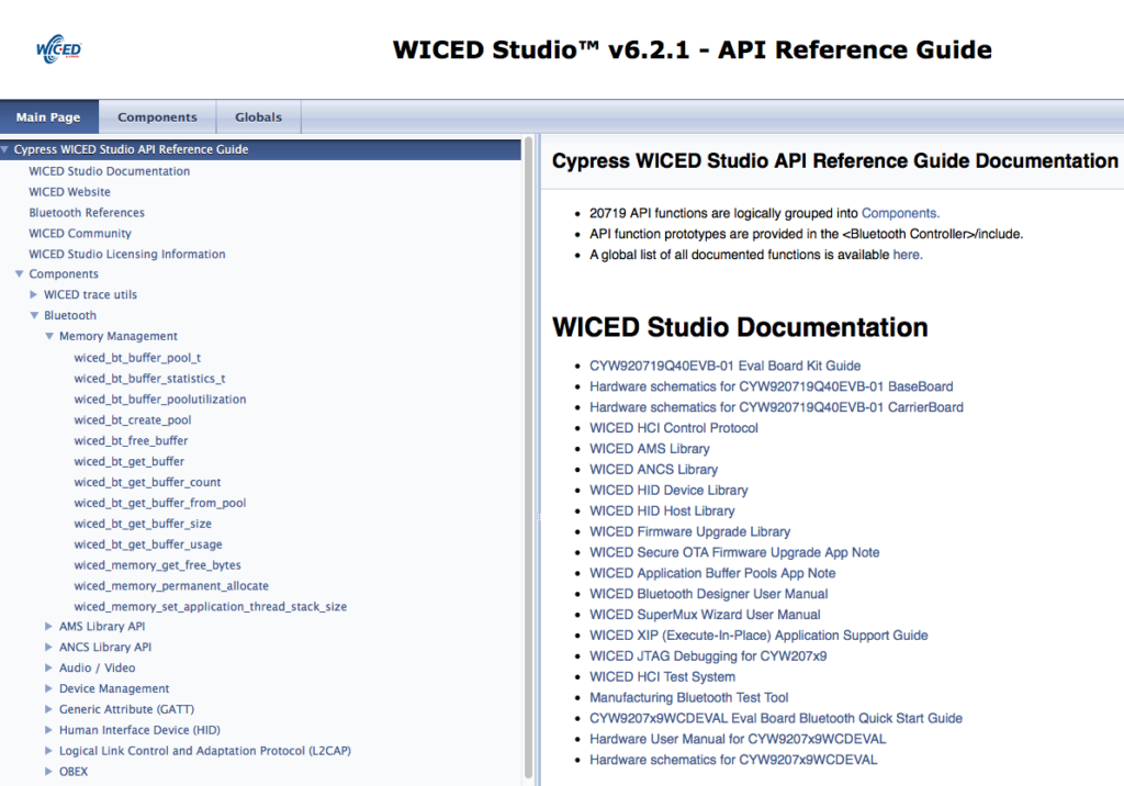
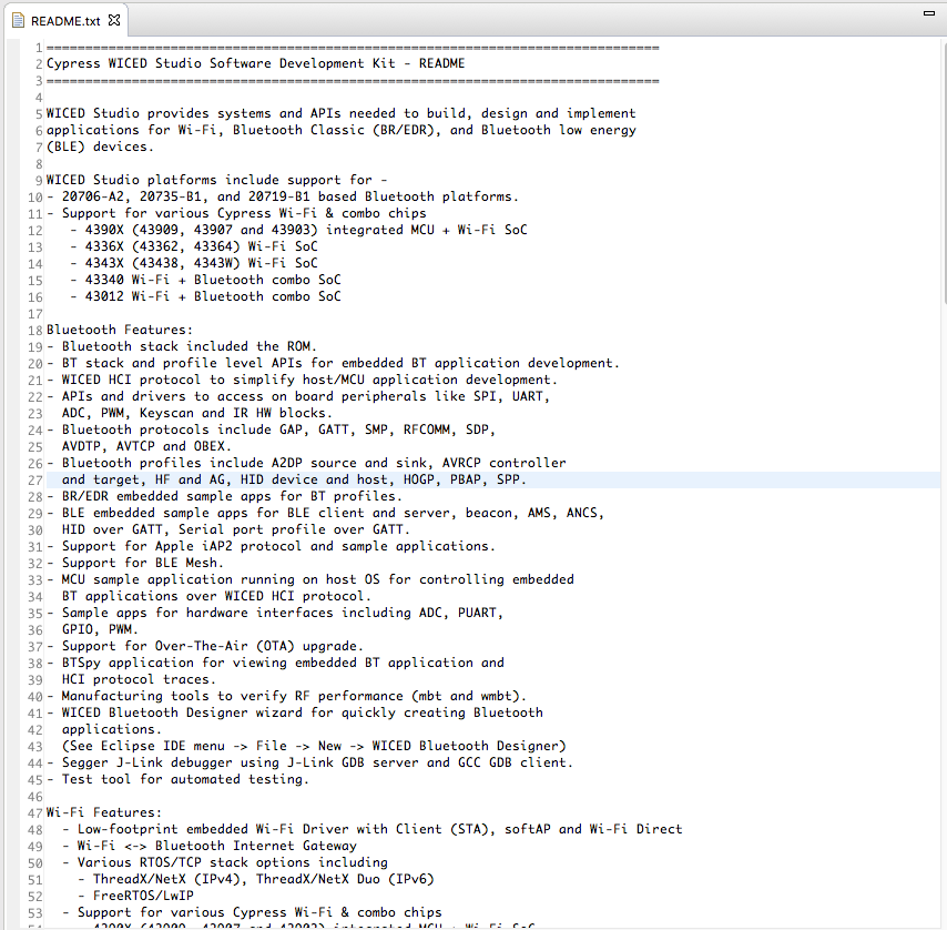
Resources
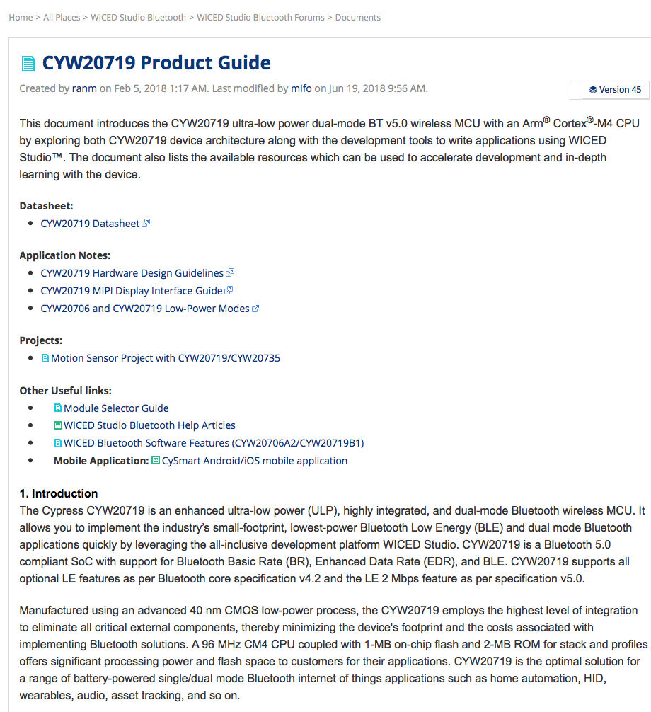
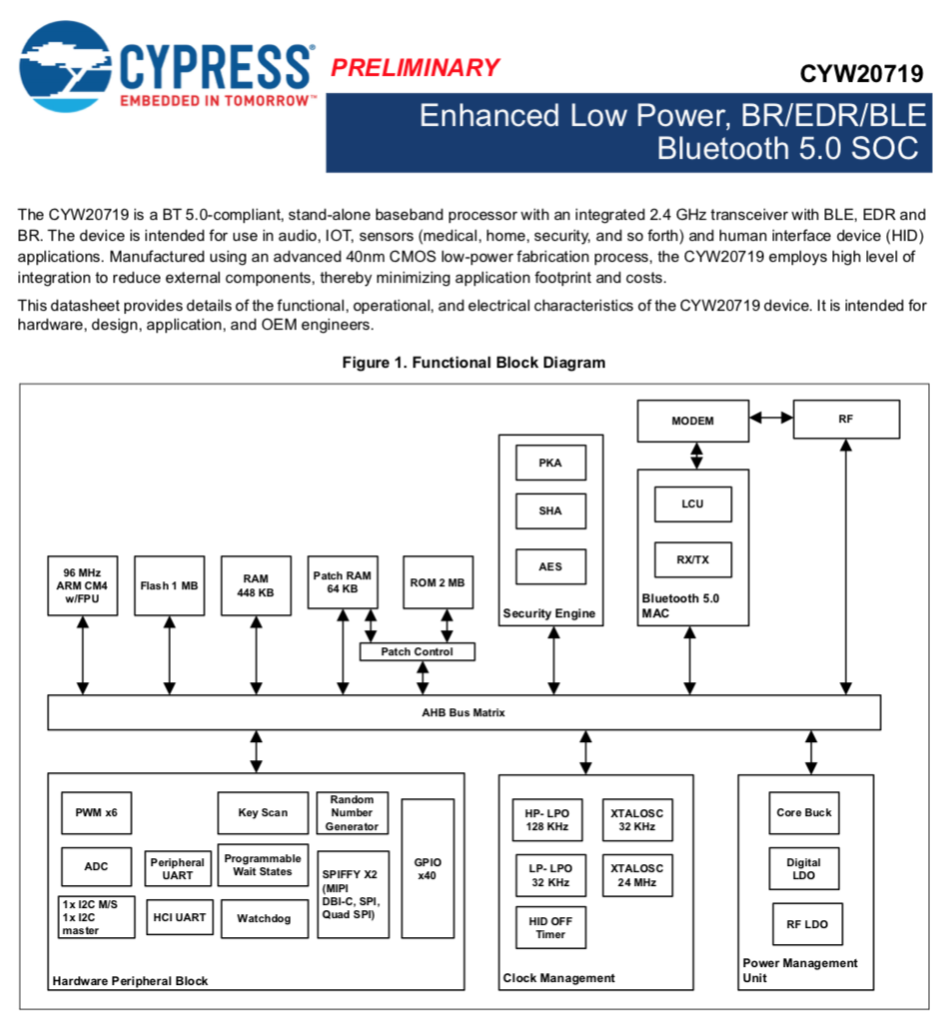
Links to all of the Cypress WICED information including videos, application notes etc.
2
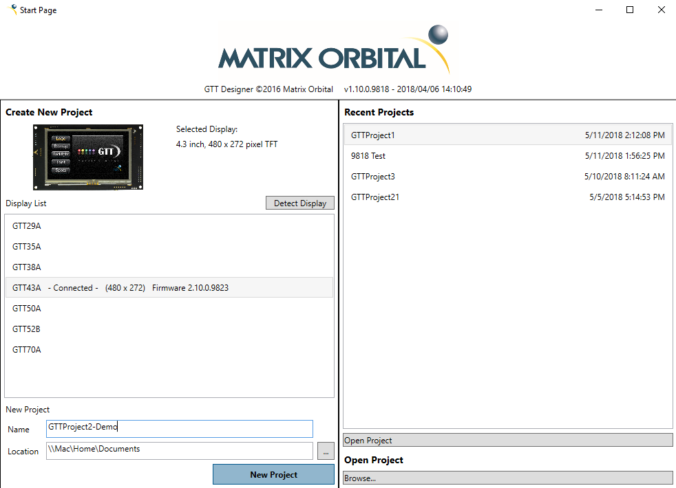
Your First Project
Making Hello World & the Blinky LED
3
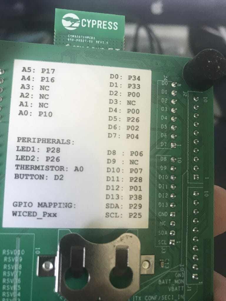
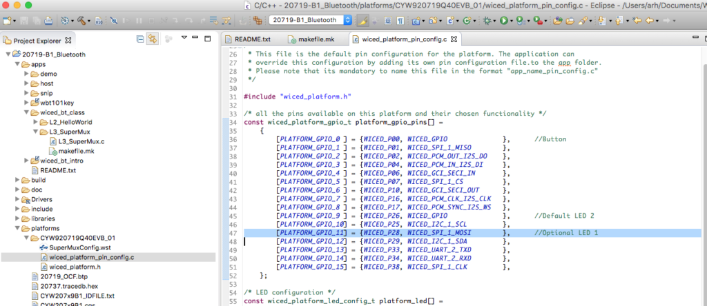
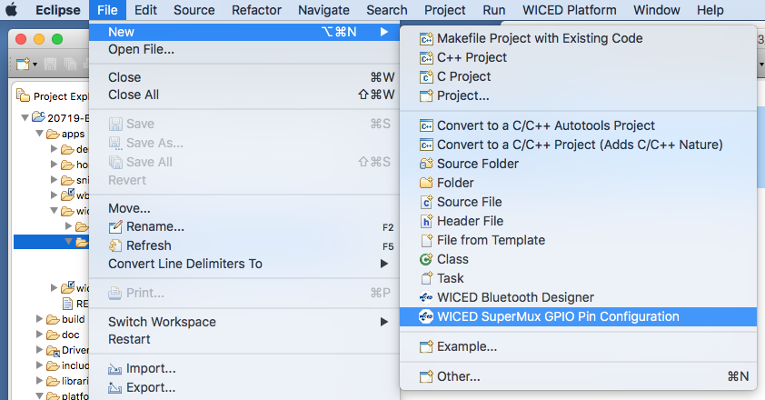
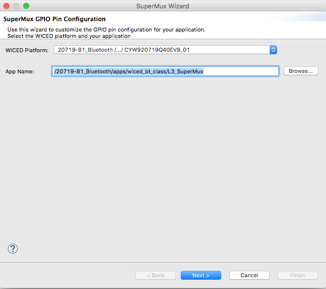
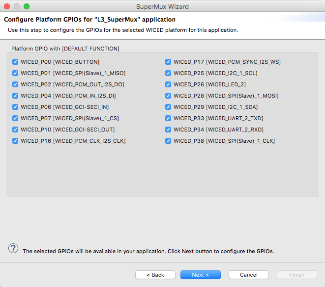
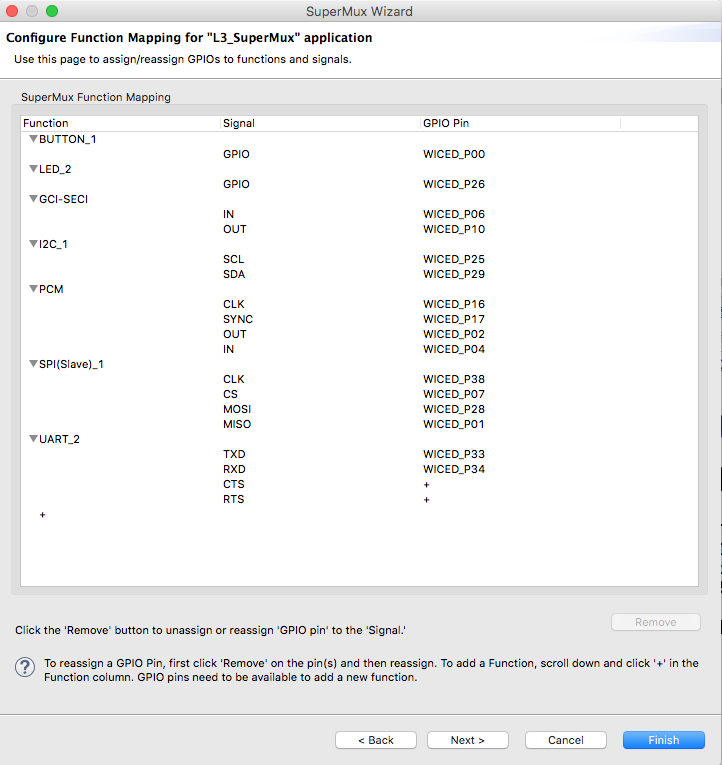
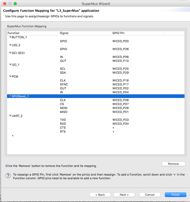
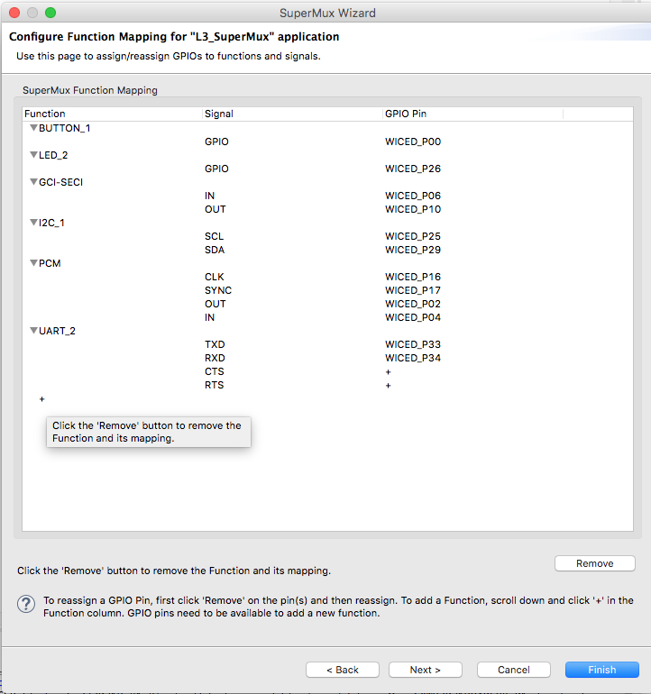
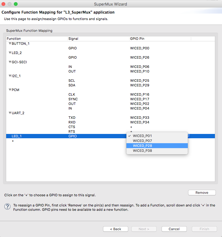
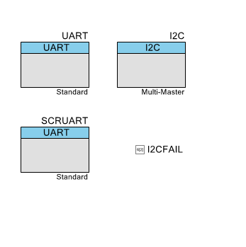
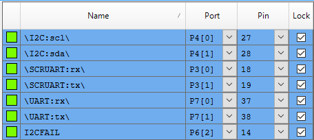
The Super Mux Tool
Learning about platforms and the Super Mux Tool
4
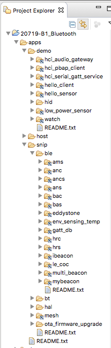
Snips
Using the example projects to learn Bluetooth
5
Bluetooth Designer
Using the tool to customize a project and get going fast
6
The CCCD & Notification
Writing back to the Central
7
Advertising Beacon
Building a beacon project to advertise your custom information
8
Scanner
Viewing the world around you
9
Bluetooth Classic SPP
Using the Serial Port Profile to Transmit Lots of Data
Source code:
- git@github.com:iotexpert/wiced_bt_intro.git
- https://github.com/iotexpert/wiced_bt_intro
Summary
In this lesson I am going to show you how to NOT write all of your own code and still get the job done. In this lesson we are going to do three things.
- Examine & Run the hal_gpio snip
- Examine & Run the hal_i2c_master snip
- Copy the hal_i2c_master snip and make it “more better”
To modify the hal_i2c_master snip I will
- Make a new folder called L4_Accelerometer
- Copy the makefile.mk and hal_i2c_master.c into the L4_Accelerometer folder
- Create a new make target and make sure that things still work
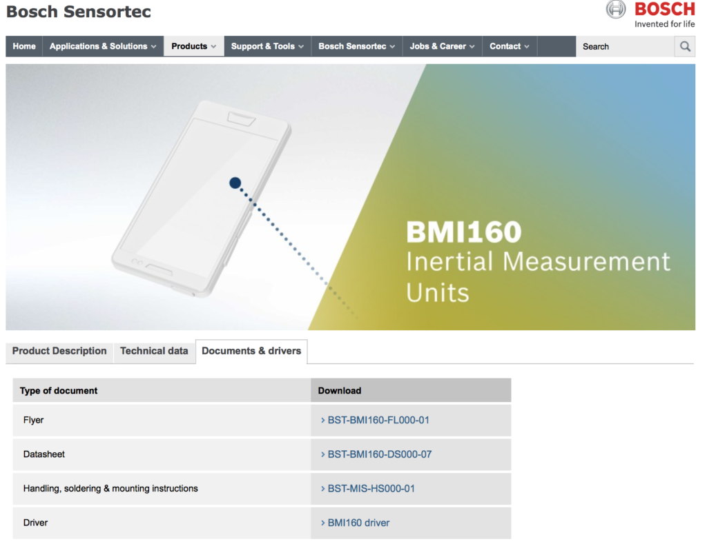
- Look at the LSM9DS1 datasheet
- Update the function initialize_app to startup the Accelerometer and speed up the polling
- Update the function comboread_cb to read the Acceleration registers and print out the values
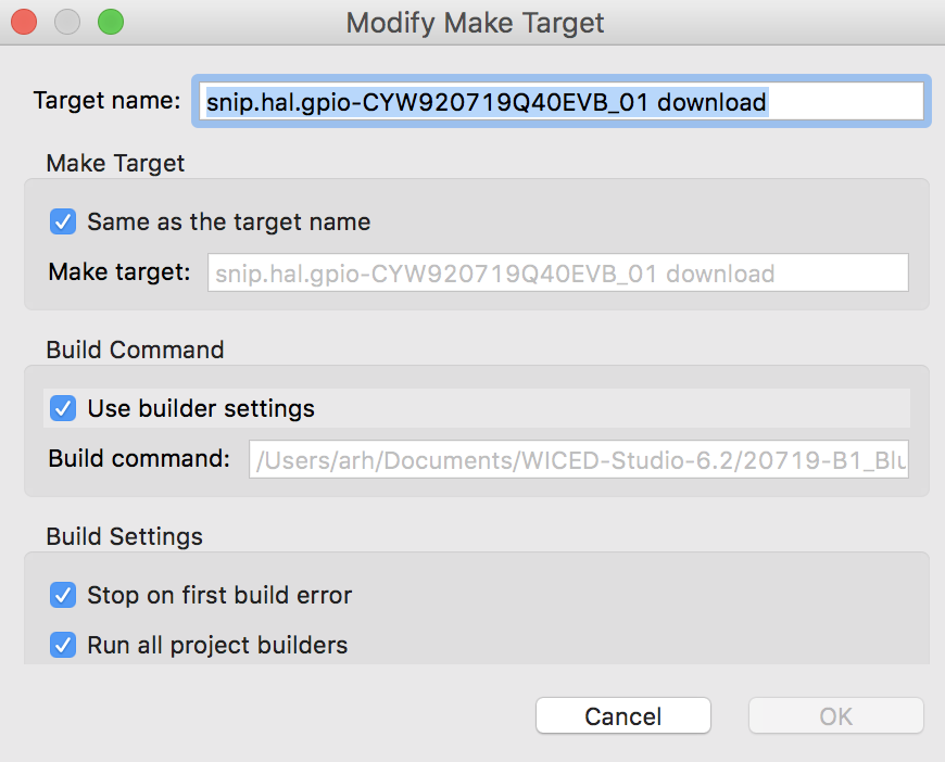
Run hal_gpio
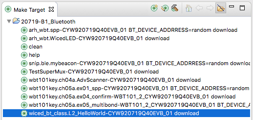
If you dont already have a make target for snip.hal.hal_gpio create one and then program the board.
Notice that the light blinking will change speeds if you press the button. Let’s look at the code that does this:
At the beginning it sets up a timer
        // Initialize timer to control the pin toggle frequency
        if (wiced_init_timer(&hal_gpio_app_timer, &hal_gpio_app_timer_cb, 0, WICED_SECONDS_PERIODIC_TIMER) == WICED_SUCCESS)
        {
            if (wiced_start_timer(&hal_gpio_app_timer, LED_BLINK_FREQ_A_IN_SECONDS) != WICED_SUCCESS)
            {
                WICED_BT_TRACE("Seconds Timer Error\n");
            }
        }
The timer calls this function each time the timer expires.
/*
 * The function invoked on timeout of app. seconds timer.
 */
void hal_gpio_app_timer_cb(uint32_t arg)
{
    static uint32_t wiced_seconds = 0; /* number of seconds elapsed */
    uint8_t index = 0;

    wiced_seconds++;

    if (wiced_seconds & 1)
    {
        for (index = 0; index < sizeof(output_pin_list); index++)
        {
            wiced_hal_gpio_set_pin_output(output_pin_list[index], GPIO_PIN_OUTPUT_LOW);
        }
    }
    else
    {
        for (index = 0; index < sizeof(output_pin_list); index++)
        {
            wiced_hal_gpio_set_pin_output(output_pin_list[index], GPIO_PIN_OUTPUT_HIGH);
        }
    }
}
And when the button is pressed all it does is switch back and forth between two different intervals for the timer. And after the switch it restarts the timer.
/*
 * Handle interrupt generated due to change in the GPIO state
 */
void hal_gpio_app_interrrupt_handler(void *data, uint8_t pin)
{
    static uint32_t blink_freq = LED_BLINK_FREQ_A_IN_SECONDS;

    // toggle LED blink rate upon each button press
    if (blink_freq == LED_BLINK_FREQ_A_IN_SECONDS)
    {
        blink_freq = LED_BLINK_FREQ_B_IN_SECONDS;
    }
    else
    {
        blink_freq = LED_BLINK_FREQ_A_IN_SECONDS;
    }

    if (wiced_stop_timer(&hal_gpio_app_timer) == WICED_SUCCESS)
    {
        wiced_start_timer(&hal_gpio_app_timer, blink_freq);
    }

    // clear the interrupt status
    wiced_hal_gpio_clear_pin_interrupt_status(pin);
}
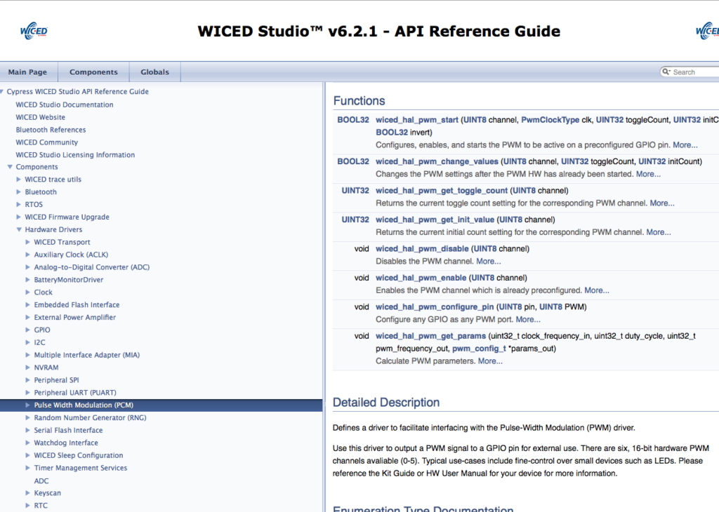
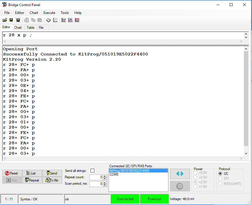
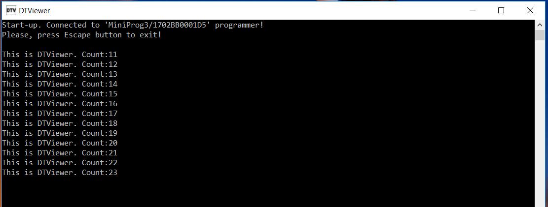
Run hal_i2c_master
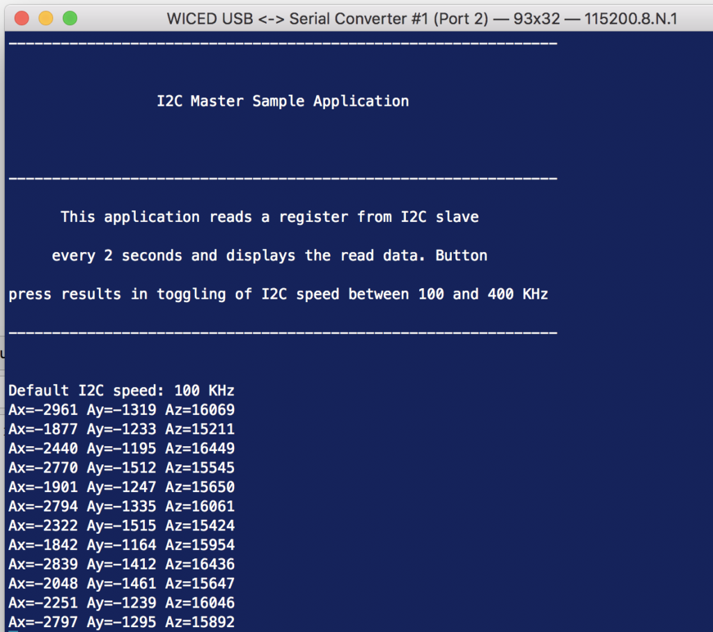
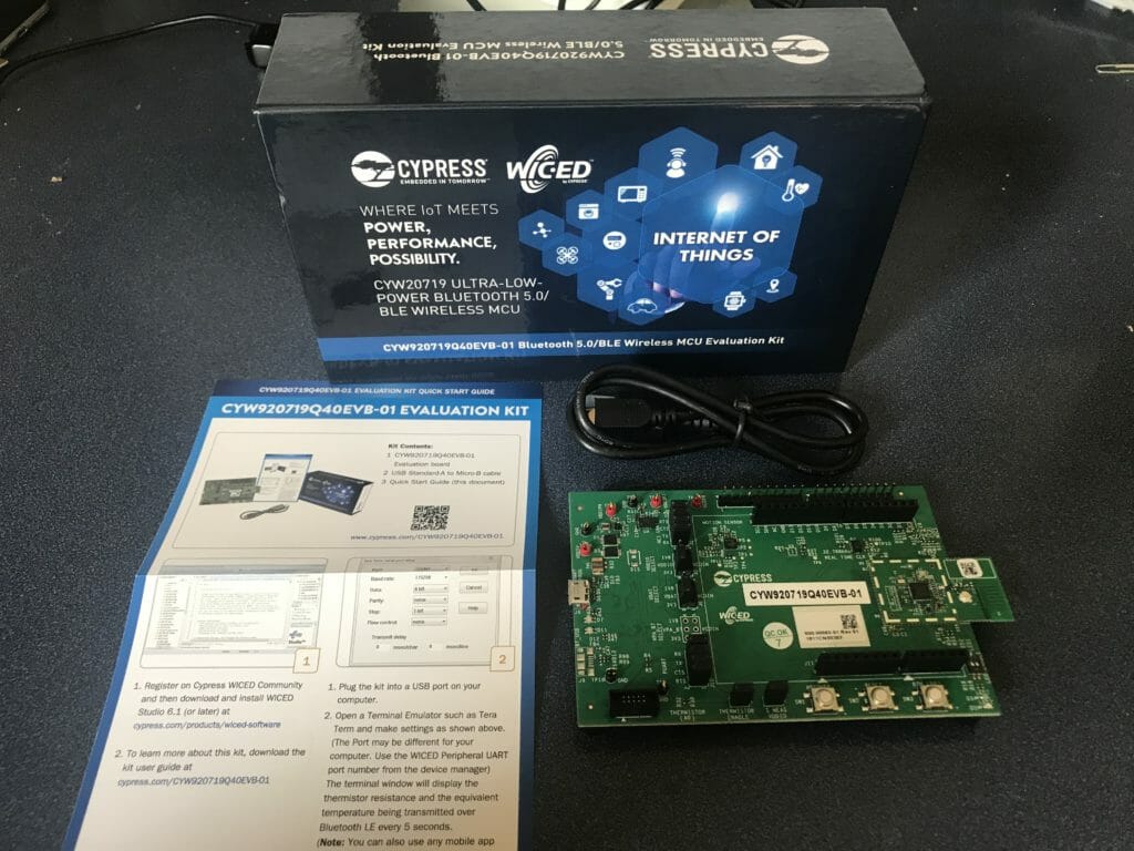
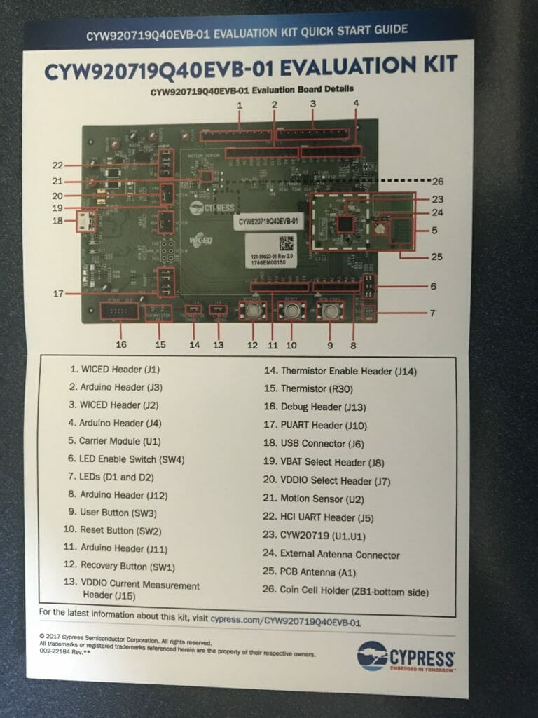
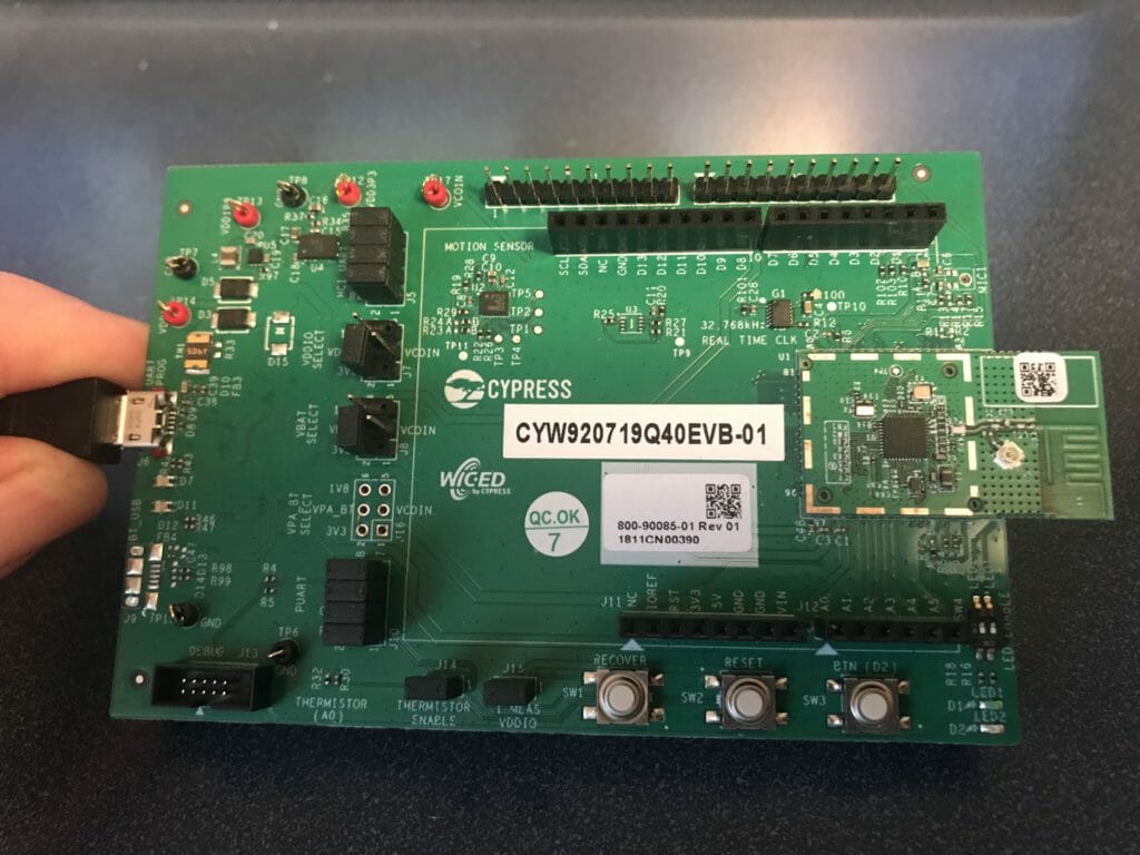
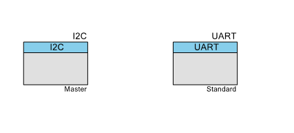
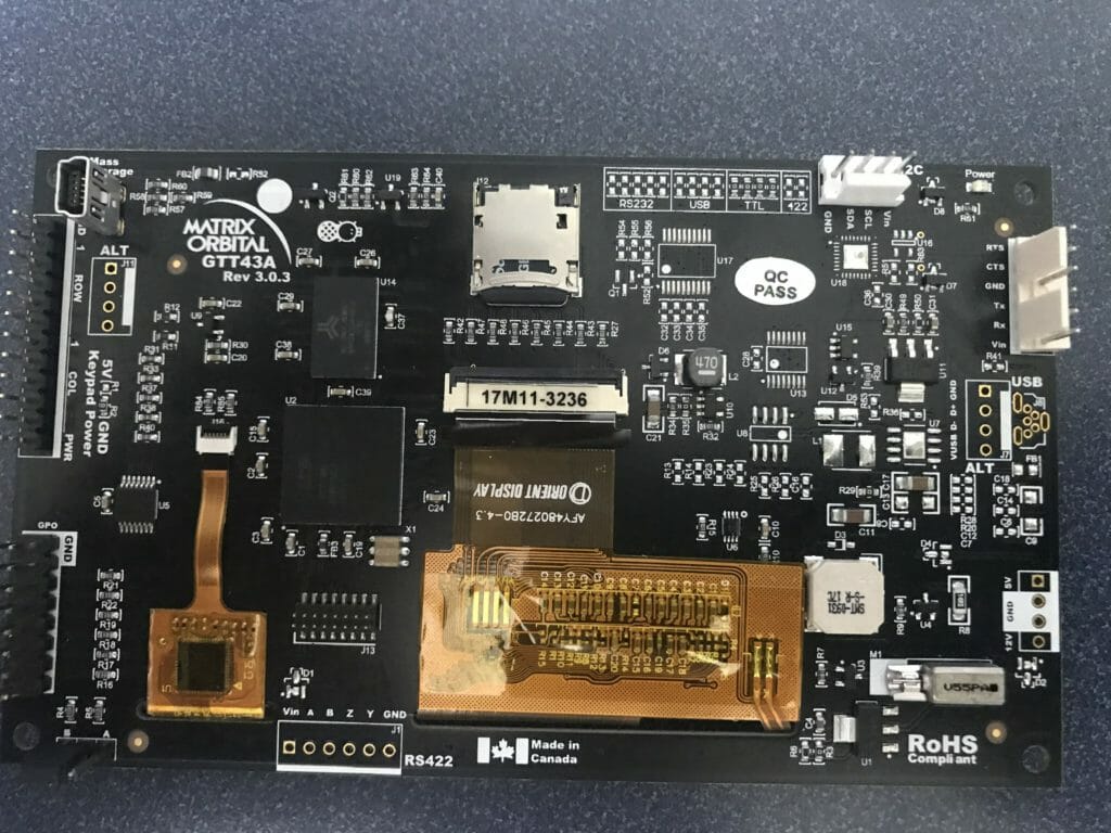
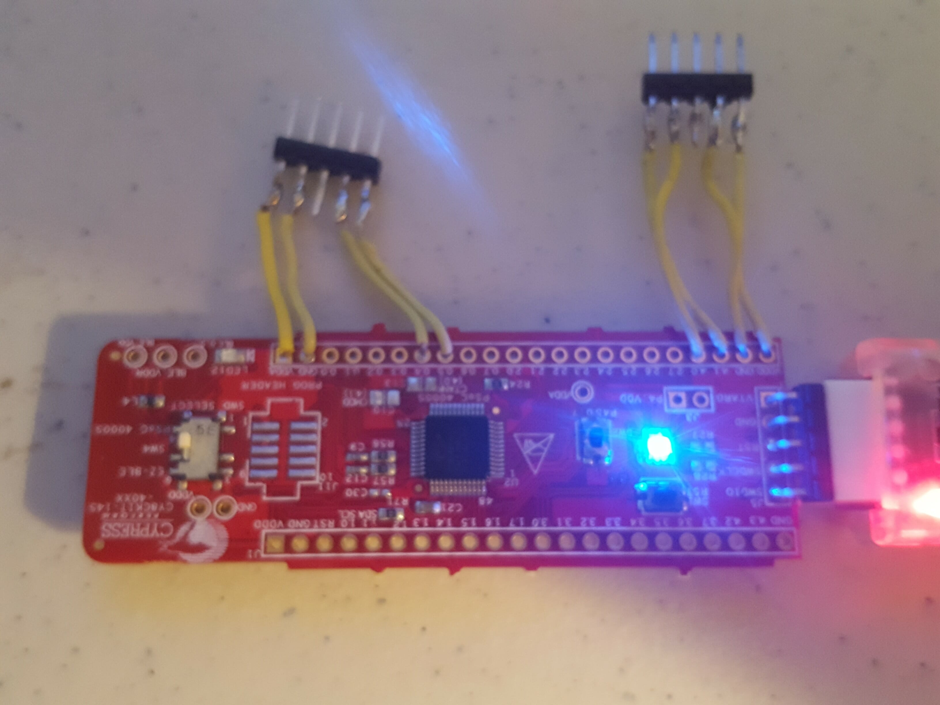
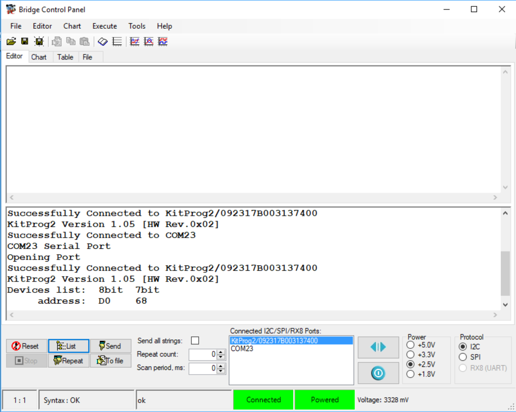
This CYW920719Q40EVB_01 development kit has an I2C LSM9DS1 accelerometer on it. And I noticed that when looking around in the snips that the Snip called “hal_i2c_master.c” appears to talk to the chip. Here is a little section of the comments from the top of the snip
 *
 * WICED sample application for I2C Master usage
 *
 * This application demonstrates how to use I2C driver interface
 * to send and receive bytes or a stream of bytes over the I2C hardware as a master.
 * The on-board LSM9DS1 motion sensor acts as the I2C slave
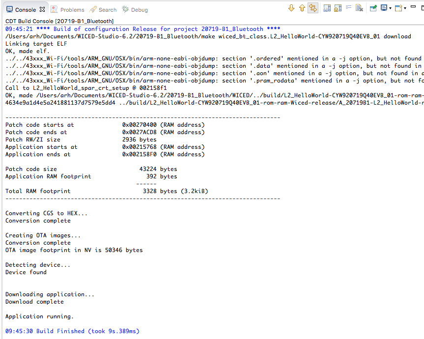
So, lets run the snip and see what happens. If you don’t have a make target… well then make one.
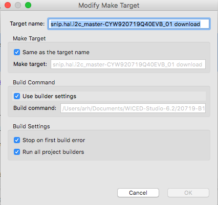
Then make the make target.
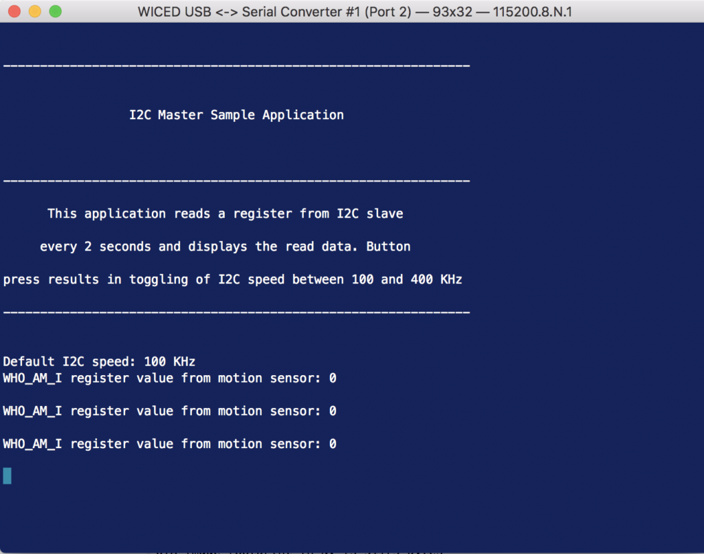
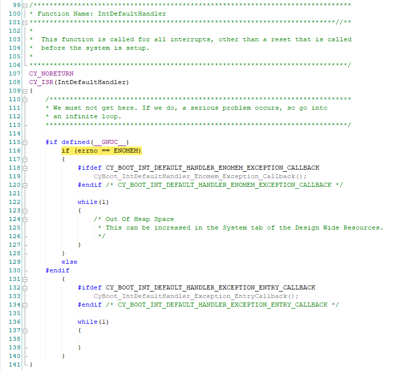
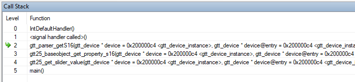
It turns out that “0” is a bug in the example project. And printing out the WHO_AM_I register isnt really very interesting.
Modify the hal_i2c_master.c Create a Better Project
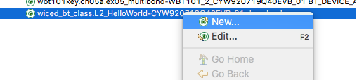
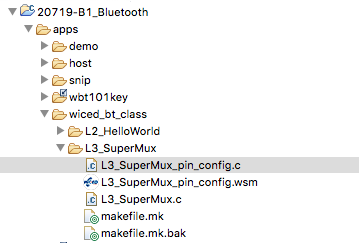
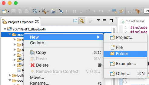
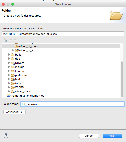
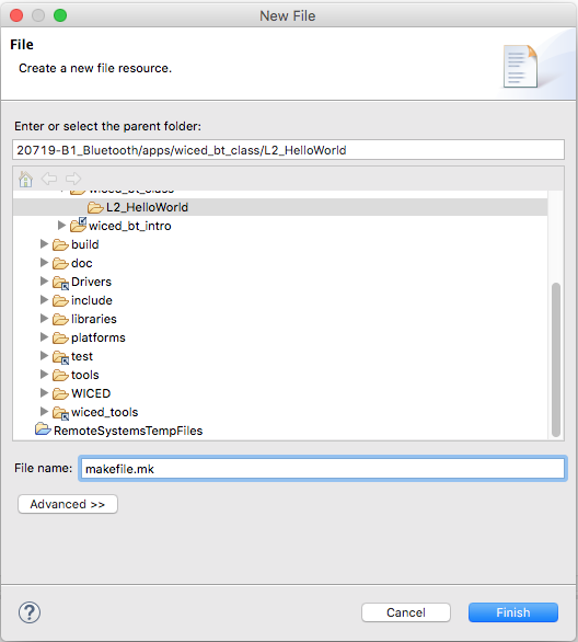
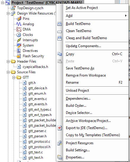
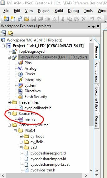
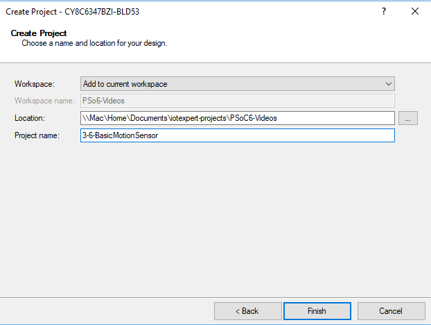
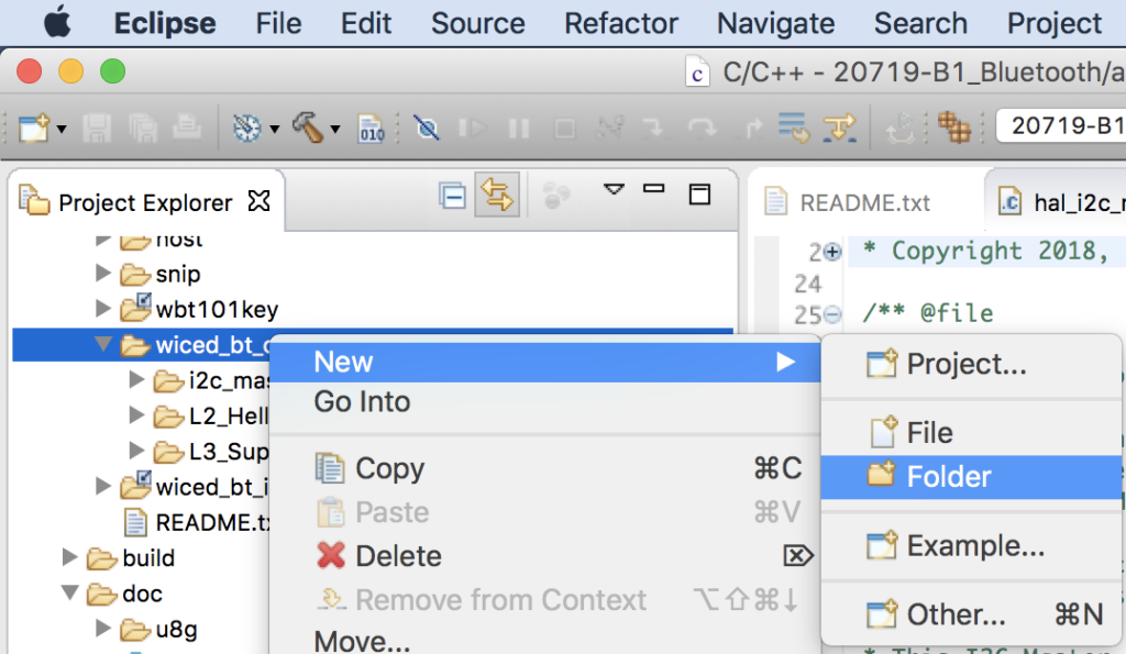
I don’t like making changes inside of the WICED SDK files. But, I want to fix the bug and printout something more interesting. So start by creating a new folder in the wiced_bt_class folder
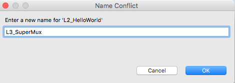
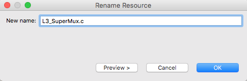
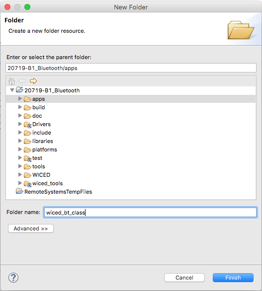
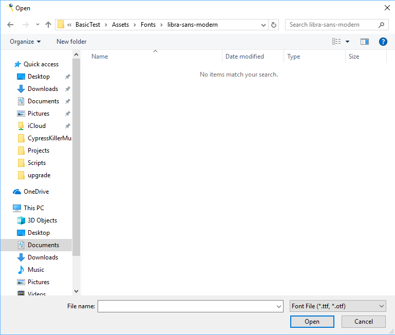
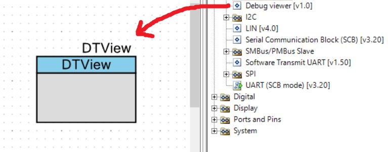
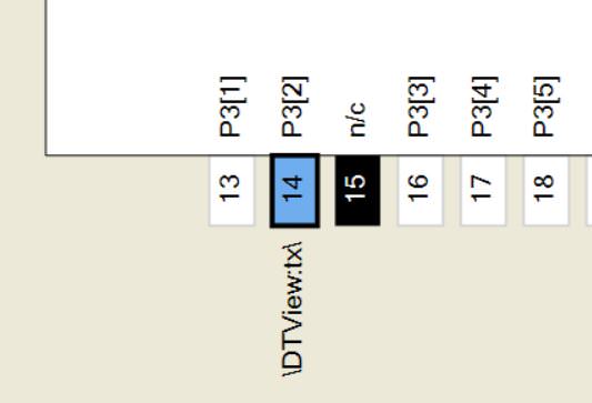
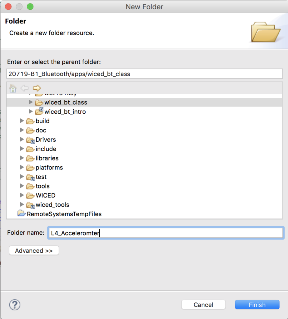
Type in the directory name L4_Accelerometer (notice in the screenshot below I mistyped it)
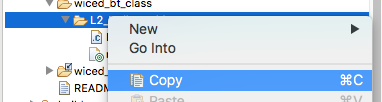
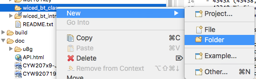
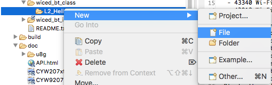
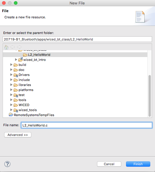
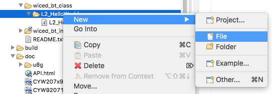
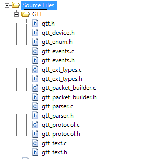
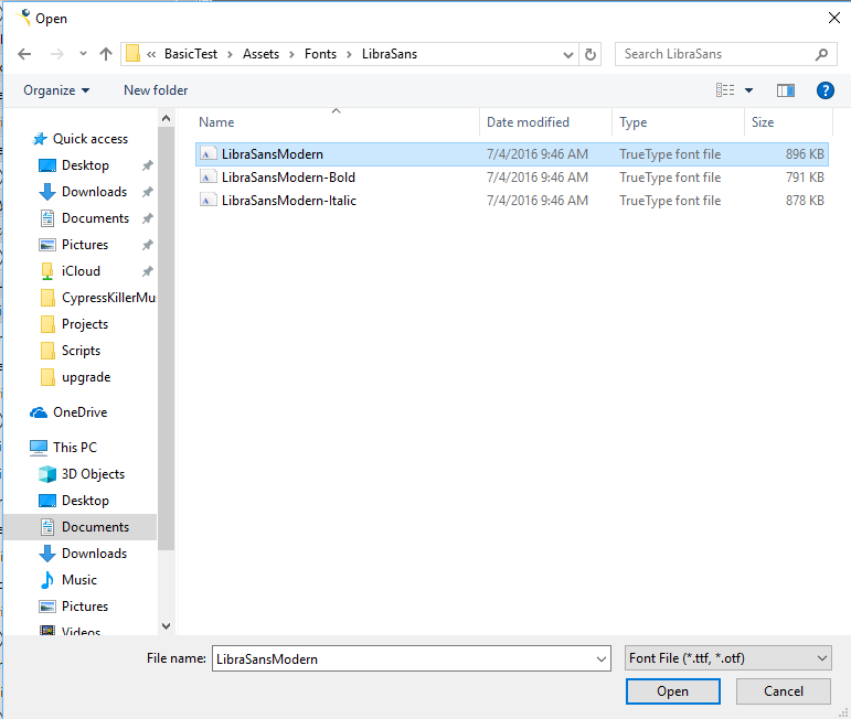
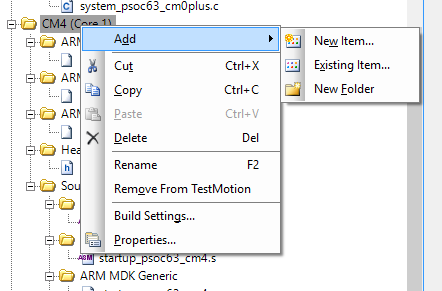
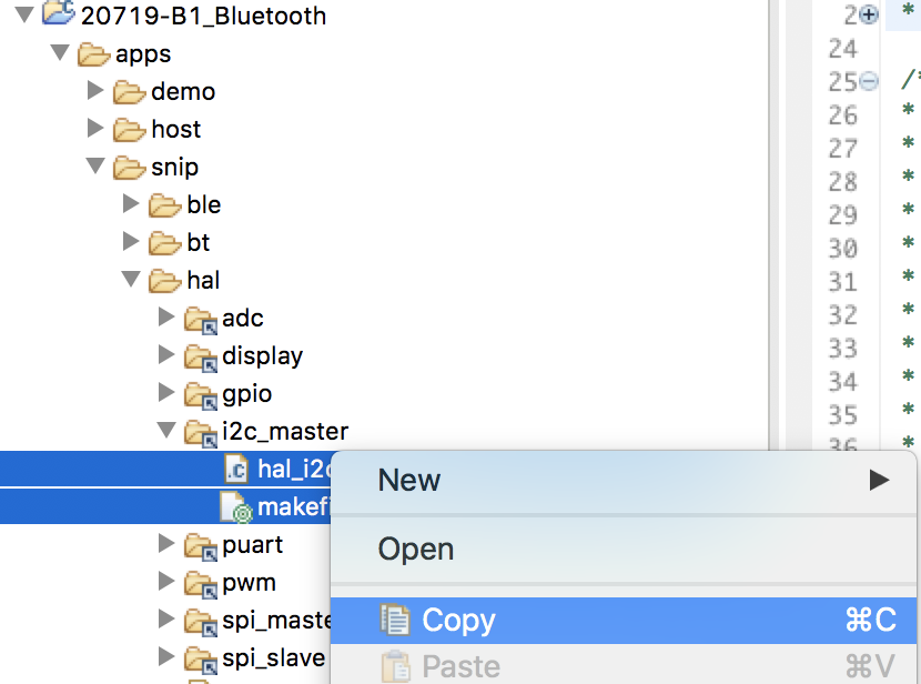
Select the makefile.mk and the hal_i2c_master.c then right click copy the files.
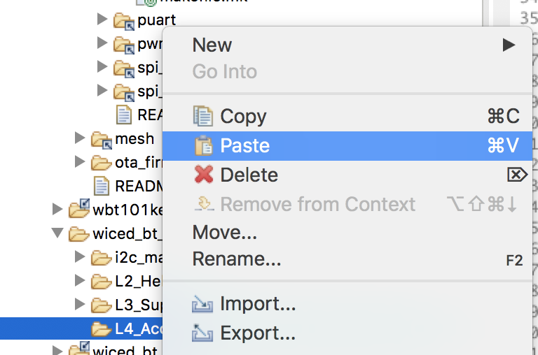
Then select the L4_Accelerometer folder and pick paste.
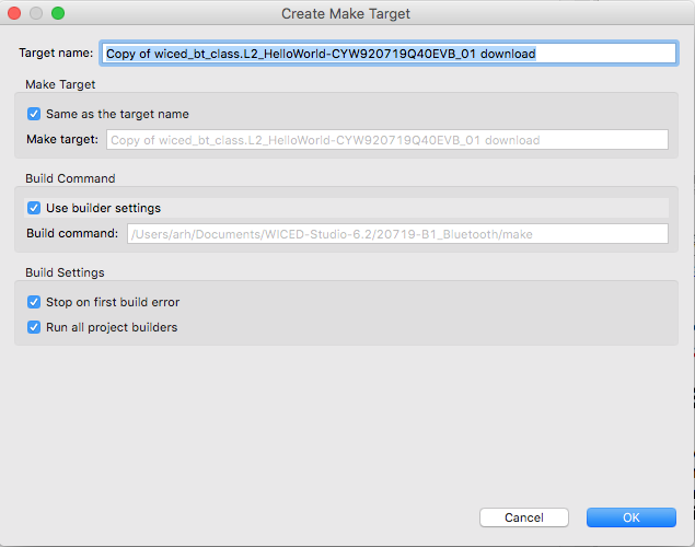
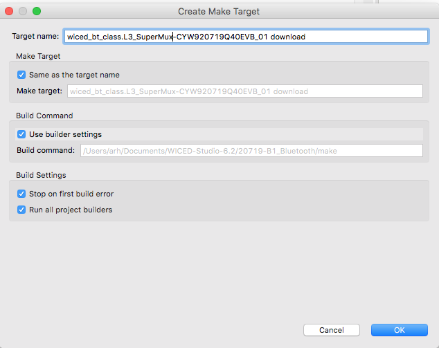
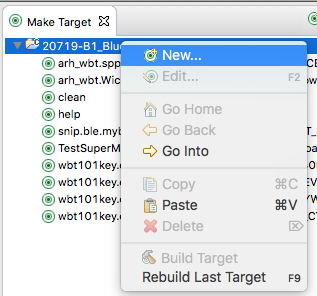
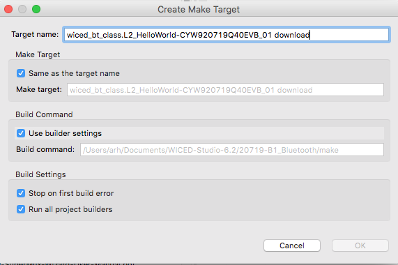
Create a make target for the L4_Accelerometer
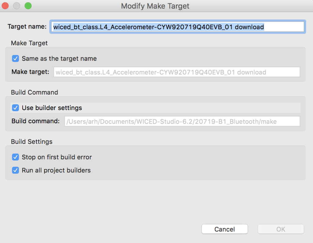
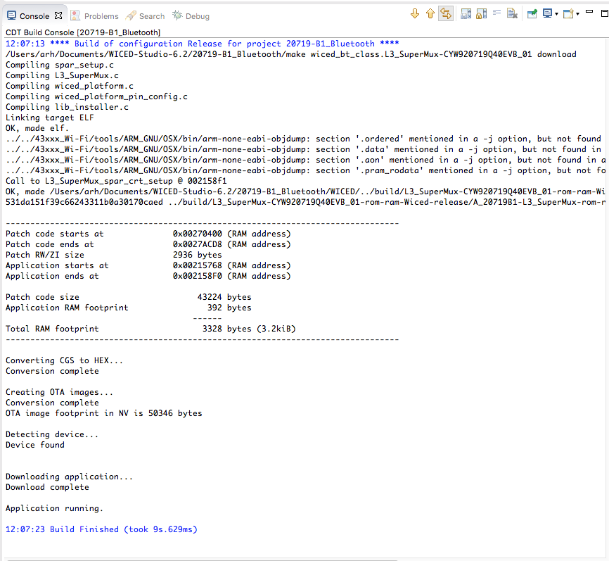
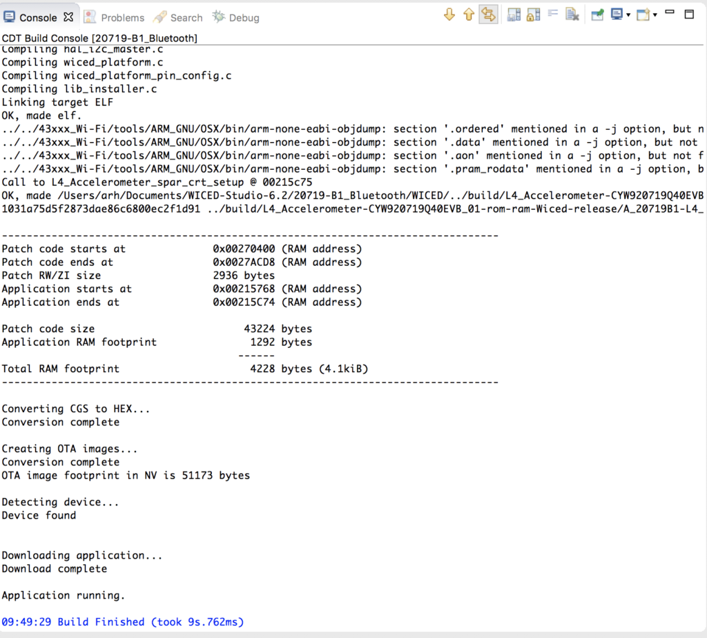
Build it to make sure it still works.
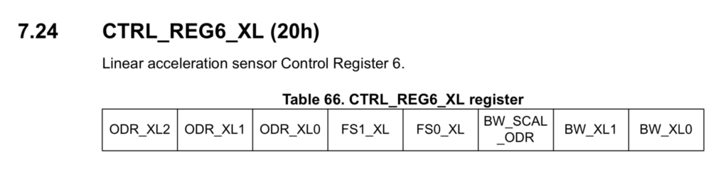
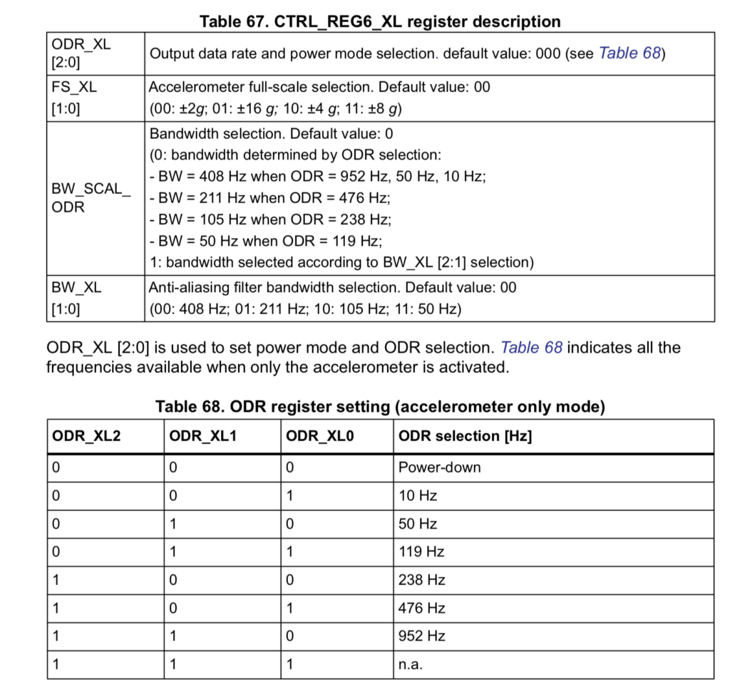
Now that we have a base to stand-on. Let’s have a look at the data sheet. I have used these before and I know that you need to turn on the Accelerometer to give you anything interesting. Turns out CTRL_REG_6_XL is the control register we need.
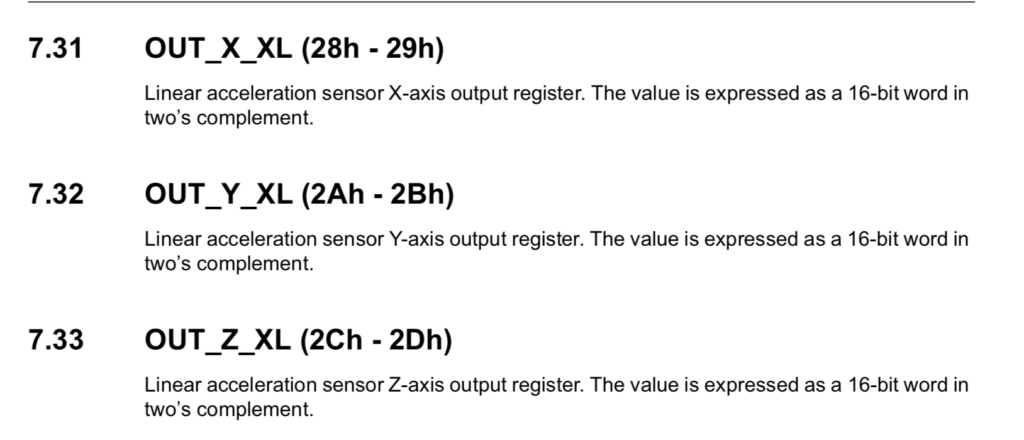
The other interesting registers are the actual output of the accelerometer. That is 0x28 –> 0x2D
Start by modifying the function initialize_app to turn on the accelerometer by writing 0x40 to register 0x20
uint8_t status;
    // Turn on Accelerometer - Register 0x20... 2g accelerometer on @ 50hz
    uint8_t data[] = {0x20, 0x40};
    status = wiced_hal_i2c_write(data,sizeof(data),LSM9DS1_ACC_GYRO_I2C_ADDRESS);
I dont really like printing the values every two seconds so I will modify the timer:
- Make it a milisecond timer
- Set it to print every 500ms
if ( WICED_SUCCESS == wiced_init_timer( &seconds_timer, &comboread_cb, 0, WICED_MILLI_SECONDS_PERIODIC_TIMER )) {
        if ( WICED_SUCCESS != wiced_start_timer( &seconds_timer, 500 )) {
            WICED_BT_TRACE( "Seconds Timer Error\n\r" );
        }
    }
Here is the whole function initialize_app together
void initialize_app( void )
{
    wiced_hal_i2c_init();
    uint8_t status;

    // Turn on Accelerometer - Register 0x20... 2g accelerometer on @ 50hz
    uint8_t data[] = {0x20, 0x40};
    status = wiced_hal_i2c_write(data,sizeof(data),LSM9DS1_ACC_GYRO_I2C_ADDRESS);


    /* register callback for button available on the platform */
    wiced_platform_register_button_callback( WICED_PLATFORM_BUTTON_1, button_cb, NULL, WICED_PLATFORM_BUTTON_RISING_EDGE);

    current_speed = wiced_hal_i2c_get_speed();

    WICED_BT_TRACE("Default I2C speed: %d KHz\n", (CLK_FREQ/current_speed));

    /*Start a timer for POLL_TIMER seconds*/

    if ( WICED_SUCCESS == wiced_init_timer( &seconds_timer, &comboread_cb, 0, WICED_MILLI_SECONDS_PERIODIC_TIMER )) {
        if ( WICED_SUCCESS != wiced_start_timer( &seconds_timer, 500 )) {
            WICED_BT_TRACE( "Seconds Timer Error\n\r" );
        }
    }

}
Next I need to modify the comboread_cb callback. It will
- Setup a structure to hold the three acceleration values (Line 145)
- Then it will read from the LSM9DS1 (Line 152)
- Then print them (Line 156)
/******************************************************************************
* This function reads the value from I2C slave and prints it
*****************************************************************************/
void comboread_cb (uint32_t arg)
{
UINT8 status = 0xFF;
UINT8 reg_add = 0x28; // Acceleromter register
typedef struct {
int16_t ax;
int16_t ay;
int16_t az;
} __attribute__((packed)) accel_val_t;
accel_val_t data;
status = wiced_hal_i2c_combined_read((UINT8 *)®_add, sizeof(UINT8), (uint8_t *)&data, sizeof(data), LSM9DS1_ACC_GYRO_I2C_ADDRESS);
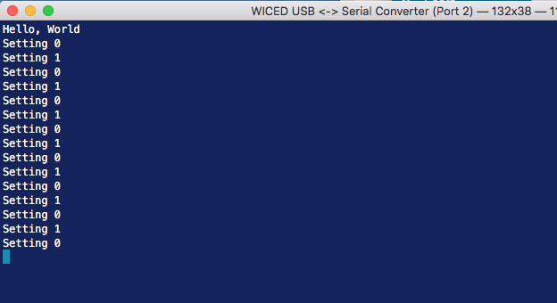
if(I2CM_SUCCESS == status) {
WICED_BT_TRACE("Ax=%d Ay=%d Az=%d\n",data.ax,data.ay,data.az);
}else if(I2CM_OP_FAILED == status) {
WICED_BT_TRACE("I2C comboread operation failed\r\n");
}else if(I2CM_BUSY == status) {
WICED_BT_TRACE("I2C busy\r\n");
}else{
WICED_BT_TRACE("Unknown status from I2C\r\n");
}
}
Now double click the make target and make sure that everything is working.