Summary
In this article Im going to show you how to build a driver for the Matrix Orbital GTT43A that I have been talking about in the last several articles. As you can see from the protocol manual, the Matrix Orbital Display has a bunch of different commands. And I know that I need a driver. But there isn’t (yet) one on the Matrix Orbital Website. However, when I look at the pre-release of the GTT25 protocol guide, it seems clear that they are planning on one. But what to do in the interim? As usual Google is your friend and after looking around a little bit I found this YouTube video of a Matrix Orbital Demo. One more Google search lead me to this Matrix Orbital GitHub repo which appears to hold the driver that they wrote for this demo.
Clone it! Clone it! Good.
Now what? In this article Ill show you:
- How to port the library to PSoC
- How to implement the HAL as conceived by Matrix Orbital
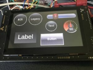
- How to make a test jig
And in the next Article I will
- Replace the HAL and Parser with a Packet based HAL, much better
- Show you how to fix some bugs in the library (nastiness)
- Add more test code
And in the one after that Ill port the whole thing to PSoC6 & RTOS
Port the GTT Client Library
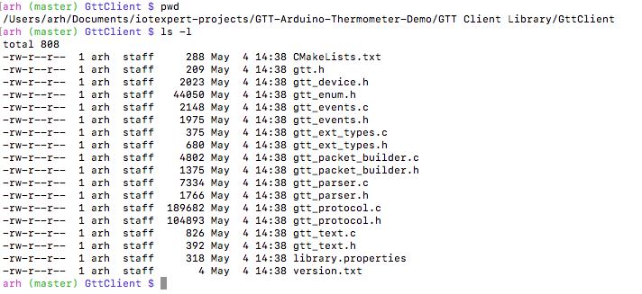
After running “git@github.com:MatrixOrbital/GTT-Arduino-Thermometer-Demo.git” I look around a little bit… and immediately find “GttClient”. And when you look there, perfect a bunch of C and Header files.
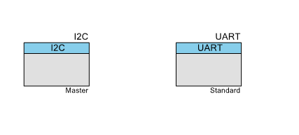
The first step is to make a new PSoC Creator project. As I have done in the past, Ill drive the display with I2C, and Ill build a command line parser to talk to the system. Here is the schematic:
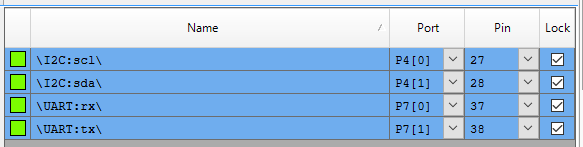
Assign the Pins (I am using a PSoC 4200M, my favorite PSoC, development kit, specifically the CY8CKIT-044)
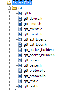
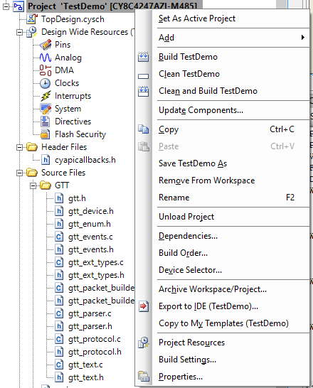
After running “Generate Application”, the next thing I do is pull in the library into PSoC Creator. To do this
- Right click on the Source Files and make a new Folder, rename it “GTT”
- Right click on the GTT Folder and do “Add Existing Item…”
- Navigate to the GttClient directory, select all of the .h and .c files
Your WorkSpace Explorer should look like this now:
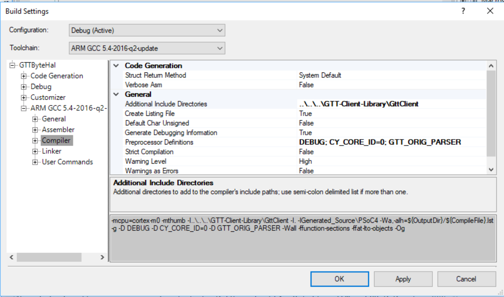
Because those files are not in the normal build path, you next need to add the directory to the include path so that PSoC Creator can find the header files. Right click on the project and pick “Build Settings”.
Then add a path to the library in the “Additional Include Directories”

Before we fix up the library to work, I always like to hit build to make sure everything is working.
Implementing the Hardware Abstraction Layer
In order to use the driver you need a Hardware Abstraction Layer. After looking around a little bit I find the “.ino” file which is the Arduino main project file. In that file, the first thing that they do is declare a structure of type “struct gtt_device”. All of the function calls to the library take a pointer to this structure. OK. Lets have a look at the structure
- First it appears that they let you store some generic data via a “Context”
- Then there are two functions to read and write data
- Then some private stuff (which is used by the packet parser)
typedef struct gtt_device
{
	void* Context;            /* device depended storage */
	gtt_write Write;          /* Function for writing data */
	gtt_read Read;            /* Function for reading data */


	uint8_t secured_packets;  /* 0 = regular protocol, 1 = wrap all outgoing packets with crc protection*/

	/* The fields below are internal and shall NOT be used by the read/write functions */

	gtt_parser Parser;        /* Protocol parser data */
	uint8_t *rx_buffer;       /* Buffer for incoming data */
	size_t rx_buffer_size;    /* size of the rx buffer in elements */
	uint8_t *tx_buffer;       /* Buffer for outgoing data */
	size_t tx_buffer_size;    /* size of the tx buffer in elements */
	size_t tx_index;          /* current index for the packet writer */
	gtt_events events;        /* Event Callbacks */
	size_t wait_idx;          /* Current Packet Index for the waitlist */
	gtt_waitlist_item waitlist[8]; /* Packet recieve waitlists */
} gtt_device;
That means you need to provide a function called “Write” and one called “Read” which reads bytes from the serial interface. Here is how they setup the structure for the Arduino Demo. Apparently they are going to make two functions called i2cWrite and i2cRead.
  gtt.Write = i2cWrite; //Set the write function
  gtt.Read = i2cRead; //Set the read function
  gtt.rx_buffer = rx_buffer; //Declare a buffer for input data
  gtt.rx_buffer_size = sizeof(rx_buffer); //Declare the size of the input buffer
  gtt.tx_buffer = tx_buffer; //Declare a buffer for output data
  gtt.tx_buffer_size = sizeof(tx_buffer); //Declare the size of the output buffer
So, what do those functions look like?
The I2C Write function just uses the Arduino Wire library to send bytes out the I2C. And the I2C read function just reads one byte from the I2C and returns it. OK I know how to do that on the PSoC
}

int i2cWrite(gtt_device* gtt_device, char* data, byte data_length) {//Write an array of bytes over i2c
  Wire.beginTransmission(I2C_Address);
  for (int i = 0; i < data_length; i++) {
    Wire.write(data[i]);
  }
  Wire.endTransmission();
  return 0;
}

byte i2cRead(gtt_device* gtt_device) { //Wait for one byte to be read over i2c
  byte data;
  Wire.beginTransmission(I2C_Address);
  Wire.requestFrom(I2C_Address, 1);
  if(Wire.available()<1)
  {
    return -1;
  }
  else{
    data = Wire.read();
    Serial.println(data);
    return data;
  }
}
To do this exact same thing on the PSoC do this. Notice that I put in a little bit of error checking. I also make complete legal I2C transactions, Start, Address, R/W, bytes, Stop
int generic_write(gtt_device *device, uint8_t *data, size_t length)
{
    (void)device;
    uint32 returncode;


    sprintf(buff,"length = %d ",length);
    UART_UartPutString(buff);


    returncode = I2C_I2CMasterSendStart( ((i2cContext_t *)device->Context)->slaveAddress,I2C_I2C_WRITE_XFER_MODE , ((i2cContext_t *)device->Context)->timeout);
    if(returncode != I2C_I2C_MSTR_NO_ERROR)
    {
        sprintf(buff,"error = %X\r\n",(unsigned int)returncode);
        UART_UartPutString(buff);
    }

    for(size_t i=0;i<length;i++)
    {
        I2C_I2CMasterWriteByte(data[i],((i2cContext_t *)device->Context)->timeout);
        sprintf(buff,"%d ",data[i]);
        UART_UartPutString(buff);
    }

    I2C_I2CMasterSendStop(((i2cContext_t *)device->Context)->timeout);
    UART_UartPutString("\r\n");
    return length;

}
And to make the PSoC read one byte at a time from the I2C do this … notice for some reason I didnt put in error checking.
int generic_read(gtt_device *device)
{
    (void)device;
     uint8 data;

    //uint32 returncode;
    I2C_I2CMasterSendStart( ((i2cContext_t *)device->Context)->slaveAddress,I2C_I2C_READ_XFER_MODE,((i2cContext_t *)device->Context)->timeout);
    I2C_I2CMasterReadByte(I2C_I2C_NAK_DATA,&data,((i2cContext_t *)device->Context)->timeout);
    I2C_I2CMasterSendStop(((i2cContext_t *)device->Context)->timeout);
    return data;
}
Matrix Orbital Parser
The Matrix Orbital Parser is build around a function which you are supposed to call every time through your main loop.
uint8_t gtt_parser_process(gtt_device *device)
If you look in this function you will find a state machine that calls the Read function pointer, then based on the value read and the state of the state machine read in the packet. Remember that there are two somewhat different packet formats, and this thing handles it.
uint8_t gtt_parser_process(gtt_device *device)
{
	int Res = device->Read(device);
	if (Res != -1)
	{
		switch (device->Parser.state)
		{
		case GTT_PARSER_IDLE:
			if (Res == 252)
				device->Parser.state = GTT_PARSER_COMMAND;
			else if (Res == 0) // Ignore 0's
            {
                return 0;
            }
I notice in gtt_parser.h that they decided to use #defines for the states, which works, but would have been better done with an enumerated datatype.
#define GTT_PARSER_IDLE       0
#define GTT_PARSER_COMMAND    1
#define GTT_PARSER_LENGTH_1   2
#define GTT_PARSER_LENGTH_2   3
#define GTT_PARSER_DATA       4
One thing that took a little but of looking at is how they handle the packets that come in. Remember from the previous articles that there are three possible sources of packets that you might read from the buffer.
- Packets that were generated by the configuration scripts residing in the display
- Packets that are generated from the user of the display doing something e.g. pressing a button
- Packets that are responses to the application sending it packets (e.g. get slider value)
They handle this by keeping a list of packets that are going to elicit a response.
The bottom line is that all of their code appears to do the right thing, and all you need to do is call the parser.
Add Test Project Code to main.c
I turns out that I am writing this Article after I already did all of the work for the next one where I replace the byte-by-byte parser with my own packet processor. In order to make that work, I #ifdef to select which packet processor to use.
#ifdef GTT_ORIG_PARSER
// The original Matrix Orbital Byte Based Parser

uint8_t gtt_parser_process(gtt_device *device)
PSoC Creator will allow you to add this to your project on the build settings dialog. If you click on the compiler option, you can then add defines to the command line on the “Preprocessor Definitions” box. Notice that I added “GTT_ORIG_PARSER”
OK now the punchline. In the main loop you need to startup the I2C, UART and setup the GTT interface. Then you loop infinitely. Read a key from the keyboard and do something based on what they press.
You can see that I call a bunch of their driver functions which all start with “gtt_”.
int main()
{
CyGlobalIntEnable; /* Enable global interrupts. */
I2C_Start();
UART_Start();
UART_UartPutString("Started\r\n");
gtt_device *gtt = >t_device_instance;
char c;
int16_t val;
while (1)
{
c = UART_UartGetChar();
switch(c)
{
case 0: break;
case 'l': gtt_draw_line(gtt, 0, 0, 480, 272); break;
case 'c': gtt_clear_screen(gtt); break;
case 'R': gtt_reset(gtt); break;
case 'v':
gtt25_get_gauge_value(gtt,9,&val);
sprintf(buff,"Gauge Value = %d\r\n",val);
UART_UartPutString(buff);
break;
case 'z':
UART_UartPutString("System Mode = IDLE\r\n");
systemMode = MODE_IDLE;
break;
case 'Z':
UART_UartPutString("System Mode = POLLING\r\n");
systemMode = MODE_POLLING;
break;
case '?':
UART_UartPutString("-------- GTT Display Functions -------\r\n");
UART_UartPutString("l\tDraw a line\r\n");
UART_UartPutString("c\tClear Screen\r\n");
UART_UartPutString("R\tReset\r\n");
UART_UartPutString("v\tGet and print value of gauge \r\n");
UART_UartPutString("-------- System Control Functions -------\r\n");
UART_UartPutString("z\tSystemMode = IDLE\r\n");
UART_UartPutString("Z\tSystemMode = POLLING\r\n");
break;
}
if(systemMode == MODE_POLLING)
gtt_parser_process(gtt);
}
return 0;
}
In the next article I am going to replace their “gtt_parser_process” with a complete packet reader.
You can "git" these projects from https://github.com/iotexpert/GTT43A And the driver library from https://github.com/iotexpert/GTT-Client-Library
Title
Matrix Orbital GTT43: A Cool Display
Matrix Orbital GTT43A: Serial Interface
Matrix Orbital GTT43A: GTT Scripts
Matrix Orbital GTT43A: A PSoC 4 Interface
Matrix Orbital GTT43A: Debugging the I2C
Matrix Orbital GTT43A: GTT Driver Library - Part 1
Matrix Orbital GTT43A: GTT Driver Library - Part 1
Matrix Orbital GTT43A: PSoC 6 using RTOS and the GTT Driver Library
No comment yet, add your voice below!