Summary
I have recently found myself way way down a rabbit hole on a project that uses a Matrix Orbital GTT43A. This display is a super cool, though expensive, intelligent touch screen display. Here is a picture:

I call it intelligent because it has a fully featured CPU that runs all of the display and touch functions for you. Basically you build all of the screens with GTT GUI elements (sliders, buttons, text etc.) using the Matrix Orbital design tool called GTT Designer. Then you program that configuration into an sd-card that is attached to the display. When you power up the display, your configuration comes up and you are off to the races. Then, in your system you can then simply interact with the display via I2C, UART, USB or SPI.
I know that it seems simple, but I will say that this has turned into quite an adventure which has, in turn, been an awesome learning experience.
Matrix Orbital GTT43A
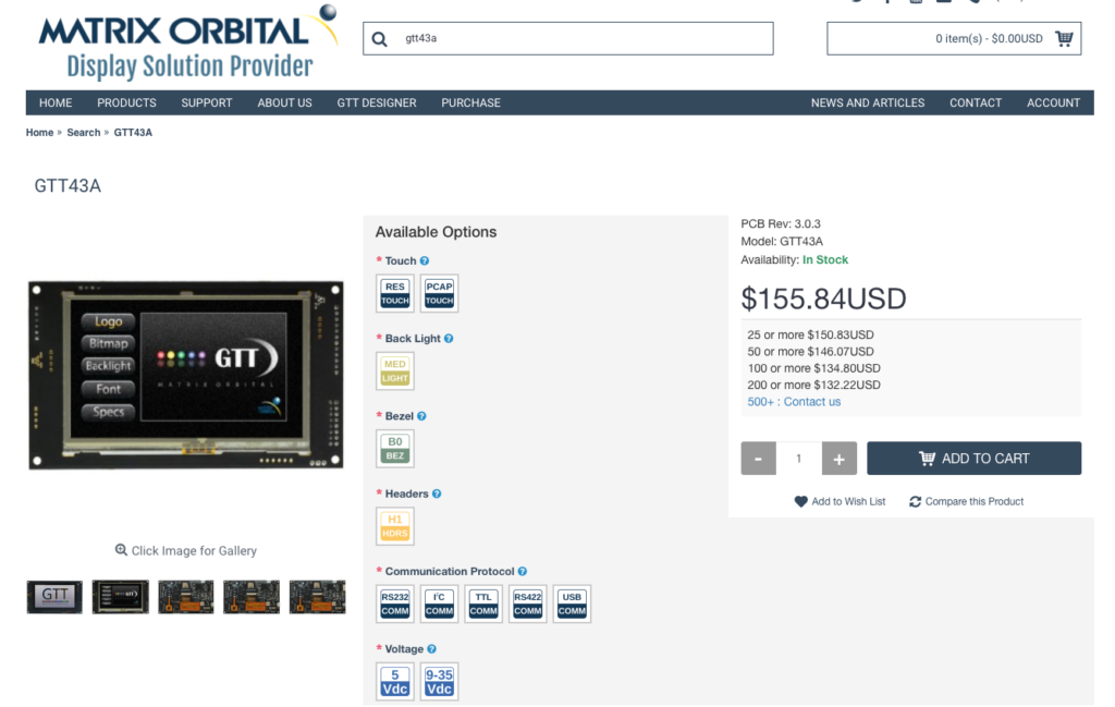
The Matrix Orbital GTT43A is a 4.3″ backlit LCD display with a capacitive touch screen. Here is a screenshot from the Matrix Orbital website. Yes, you read the price right, it is $155.84…. well actually $165.84 with capacitive touch.
Here is a picture of the back of the screen.
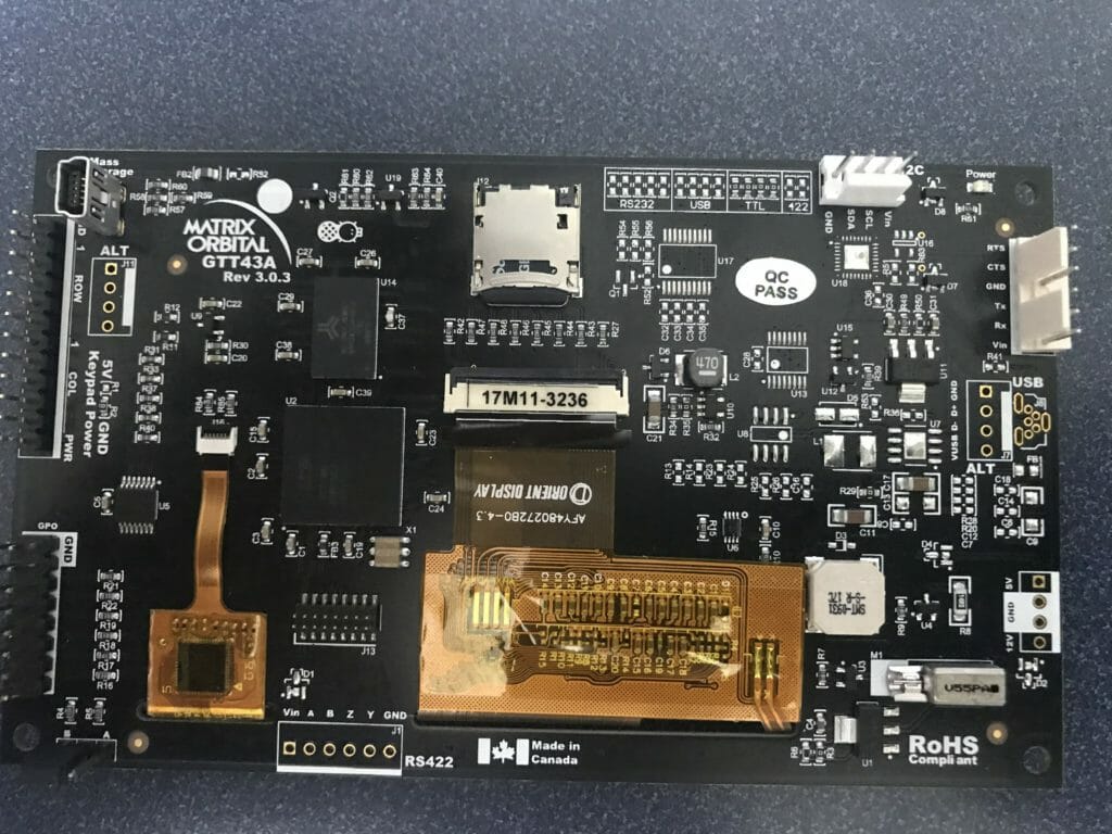
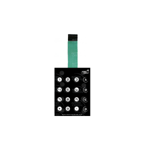
On the far left you can see the connector labeled “Keyboard Power”. This is a place where you can plug in a matrix keyboard that looks like the next picture. Though I am not exactly sure why you would make a nice touch screen interface and then use a mechanical button interface?
In the middle of the picture you can see a micro-sd card which holds all of your screen configuration information. The sd-card is a normal mass storage card and you can drag and drop your configuration, or new firmware for the screen using normal Windows. You can also put the display into mass-storage mode and then access the card via the mini-usb-b connector that is in the upper left.
The display also supports 6 digital GPIOs (which you can see on the lower left of the picture). It also has a piezoelectric buzzer and a haptic vibrator.
In order to talk to the display with your system controller you can use I2C, UART, SPI or USB. It is interesting that you seem to be able to use multiple interfaces at the same time, which is pretty convenient for debugging.
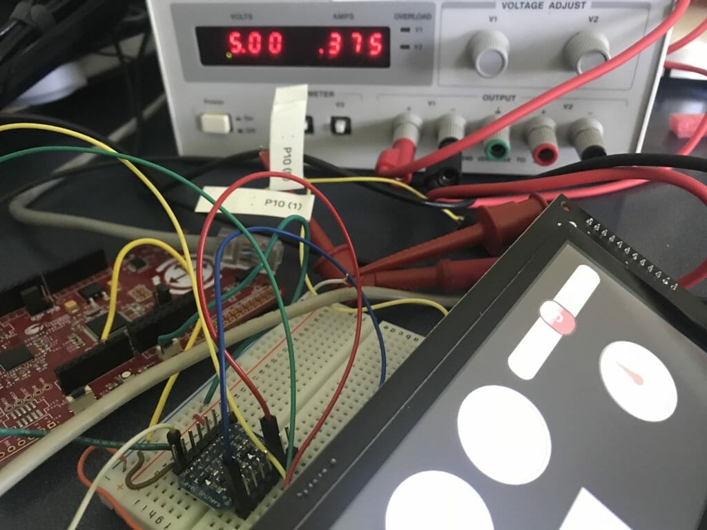
The display requires a decent amount of juice. Here is a picture on my desk, 5V and 375mA, which is more than the development kit I was using will provide. In fact it, will sort of work for a while off the devkit power supply, but when you push a button on the screen it will reboot the display.
GTT Designer
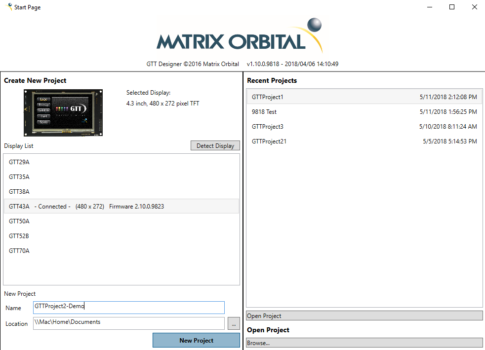
GTT Designer is a Windows GUI building tool. It is straight forward to use. When you start up the software it will give you a choice of displays to build for. In the picture below you can see that it detected that I had a GTT43A attached to my computer via USB.
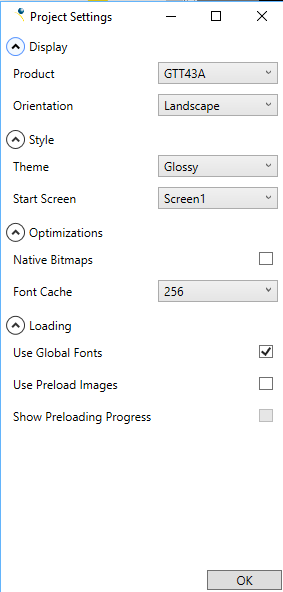
After setting up the name of my project and clicking “New Project” I am given the choice of customizing the global settings for the display.
Once the project is setup, you are now given the ability to configure the display settings. On this screen you can setup a number of things, including the I2C address of the display. Also, on the screen below you can see “Default Channel” is set to none. What this means is that any GUI thing that happens will send messages to the default channel. In this case none. But that isnt what I want so I change it to I2C (next picture)
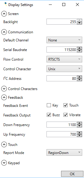
What I really want it all of the output to go to the I2C. But given that the screen is an I2C slave, and it cant send out data, what does that really mean? What it means is that all of the output goes into a buffer, that slowly fills up until you read the data out of it via I2C. If you setup the Default channel as Serial, the data will go directly out via UART.

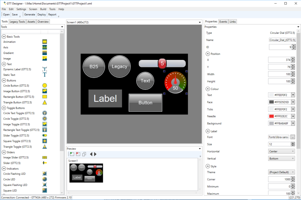
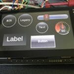
Once the display settings are done you will end up with a screen that looks like this. On the left side of the screen you can pick out the different GUI elements (buttons, text labels, sliders, images etc) and the drag them onto the screen. Notice that there are four tabs, Tools, Legacy Tools, Assets, Overview. At some point very recently Matrix Orbital did a massive re-engineering project to make things simpler to interact with the screen. When they did this, the created a who new set of widgets called “GTT2.5” widgets. You can still use the old widgets which they now call “Legacy”
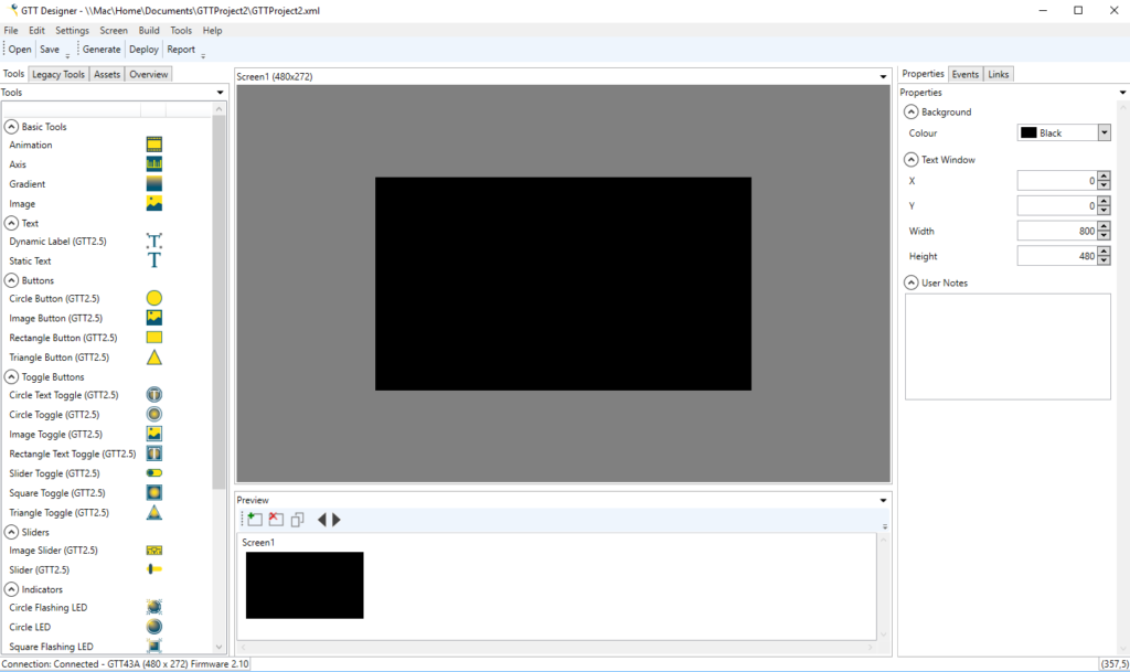
On the screen below you can see that I placed a bunch of different GUI elements for my test project. When you click on an element, the right hand side of the screen will let you update properties of the object e.g. color, size, name. You can also create events (more on that in the next article)
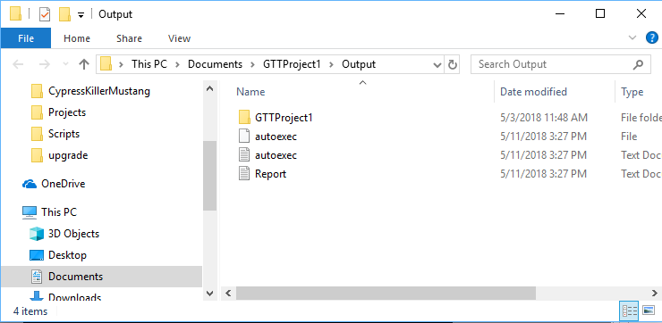
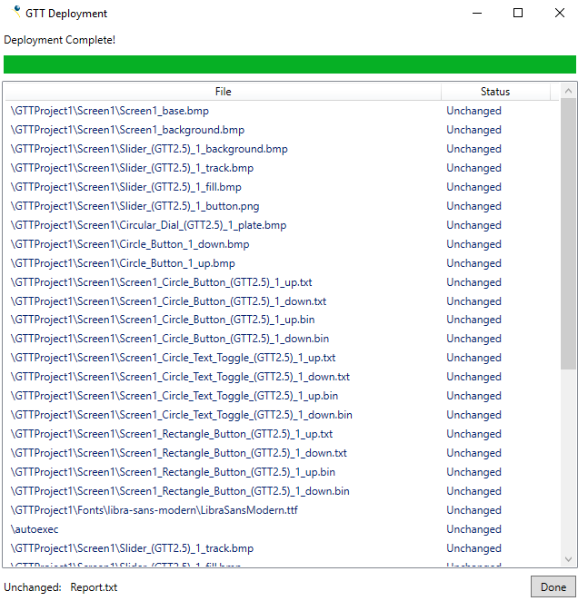
One you have drawn your screen you then want to build and program the project. Or in their language generate and deploy. To do this you can either click generate then click deploy, or just click deploy. When you do this it will first build all of your project into a directory on your computer called “Output”. There are three interesting things in the output directory.
- autoexec.txt/bin – files that contains a script that runs when the display turns on (more on that in the next article)
- Report.txt – a file that contains information about the objects, names, ids etc (this is important for your software)
- GTTProject1 – a directory with all of the files required for your project.
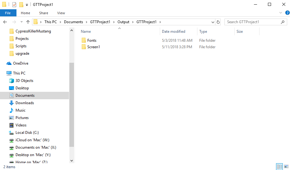
When you look in the GTTProject1 directory you will see that it contains a directory for “Screen1”. If I had made multiple screens it would have made multiple directories. It also has a directory called “Fonts”, which big surprise, contains the Fonts that are used by the project.
In the “Screen1” directory you will see a bunch of bitmap files, text files etc.
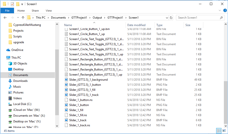
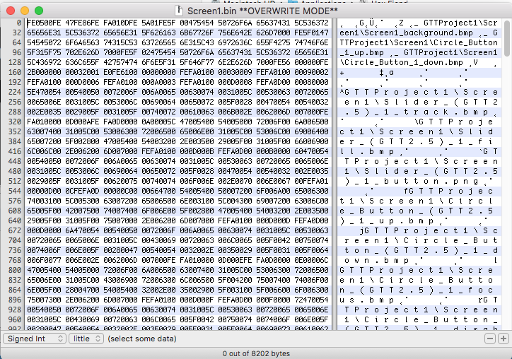
Screen1.txt contains a textual version of the “program” that creates the screen. Here is a snapshot of the top of the file.

And “Screen1.bin” which is the compiled version of the “Screen1.txt”- more on this in the next article.
When you click the deploy button, it sends a command to the screen to put it into mass storage mode which just turns the screen into a flash disk which can be written/read by your PC. Here is what the screen looks like when it is in mass storage mode:
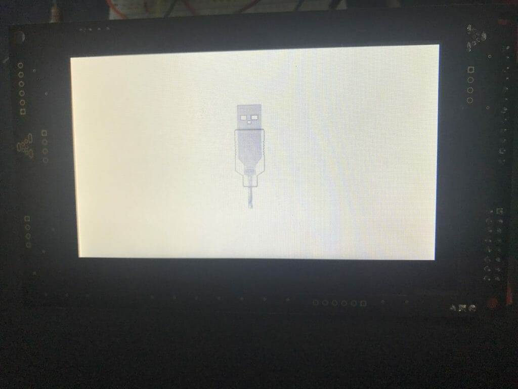
After the device is in mass storage mode, GTT Designer copies all of the file onto the sd-card of the display and the reboots the display to run the program.
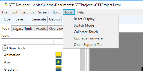
When you are running GTT Designer you can switch the display back and forth between Mass Storage mode and Display mode on the Tools menu by selecting “Switch Mode”
In the next several articles Ill show you how to build firmware to talk to the screen.
You can "git" these projects from https://github.com/iotexpert/GTT43A And the driver library from https://github.com/iotexpert/GTT-Client-Library
Title
Matrix Orbital GTT43: A Cool Display
Matrix Orbital GTT43A: Serial Interface
Matrix Orbital GTT43A: GTT Scripts
Matrix Orbital GTT43A: A PSoC 4 Interface
Matrix Orbital GTT43A: Debugging the I2C
Matrix Orbital GTT43A: GTT Driver Library - Part 1
Matrix Orbital GTT43A: GTT Driver Library - Part 1
Matrix Orbital GTT43A: PSoC 6 using RTOS and the GTT Driver Library
No comment yet, add your voice below!