Summary
In this article I will show you how to interact with the Matrix Orbital GTT43A display using the GTT Support Tool via the KitProg UART on a CY8CKIT-044 and the Bridge Control Panel via I2C. This article will be broken up into four parts
- Building a Test Project in GTT Designer
- GTT Protocol 2.0
- GTT Protocol 2.5
- GTT Support Tool
- Bridge Control Panel
Build a Test Project
In order to understand the whole serial interface, I will build a very simple project with two buttons. You can find this project in my GitHub site at git@github.com:iotexpert/GTT43A
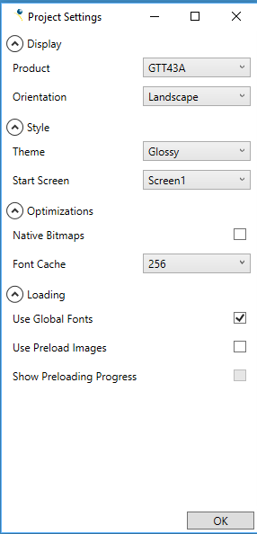
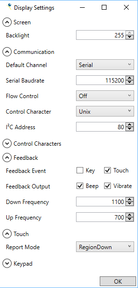
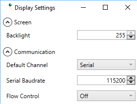
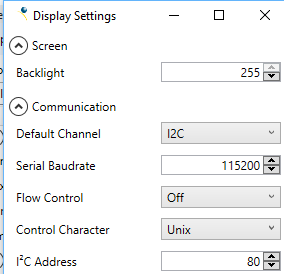
Start up a new project called “BasicTest”. Accept the defaults for Project settings. On the Display Settings screen change the “Default Channel” to Serial and the Flow Control to Off. I am using the CY8CKIT-044 to talk to the screen. On that development kit there is a KitProg which serves as a programmer (for the PSoC 4200M) and as a serial bridge. That serial bridge does not have the flow control pins turned on. If you leave the flow control on, the screen will never transmit and you will need to poke your eyeballs out trying to figure out why.
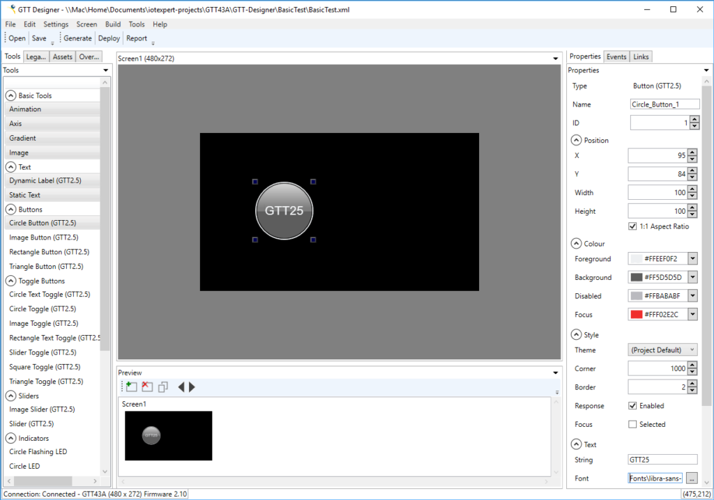
Drag a Circle Button (GTT2.5) onto the screen. Change the Text value (on the right panel) to “GTT25”
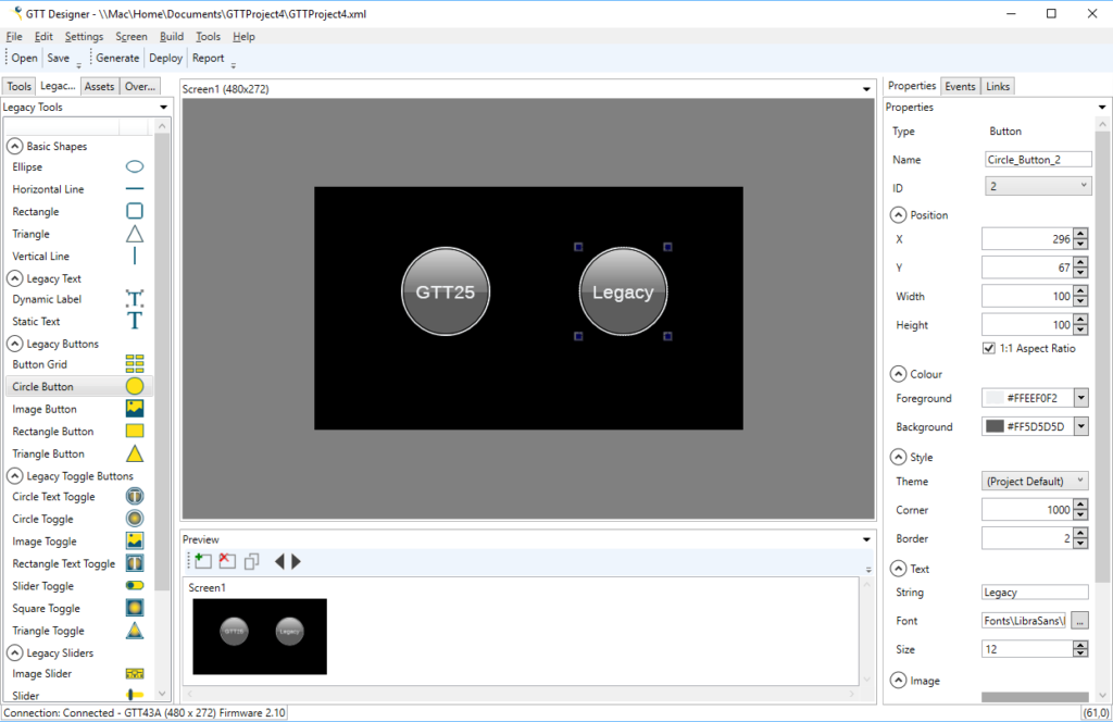
Now click on the “Legacy” tab and drag a “Circle Button” onto the screen. Then change the text label to “Legacy”. In addition change the “ID” from “Auto” to “2”. I noticed that later in this article that if the button ID is “auto” it will not be identified in the messages. Im not sure if this is a bug or my lack of understanding.
When I click “Deploy” I end up with this error message. This appears to be a bug in the GTT Designer.
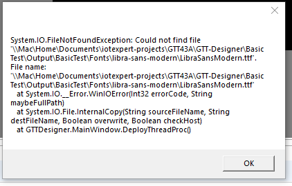
Click on the “Font” and go to the directory where the Font is supposed to be… and find that it is actually empty.
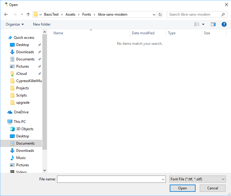
So. I navigate up a directory and then down into “LibraSans” instead of “libra-sans-modern”.
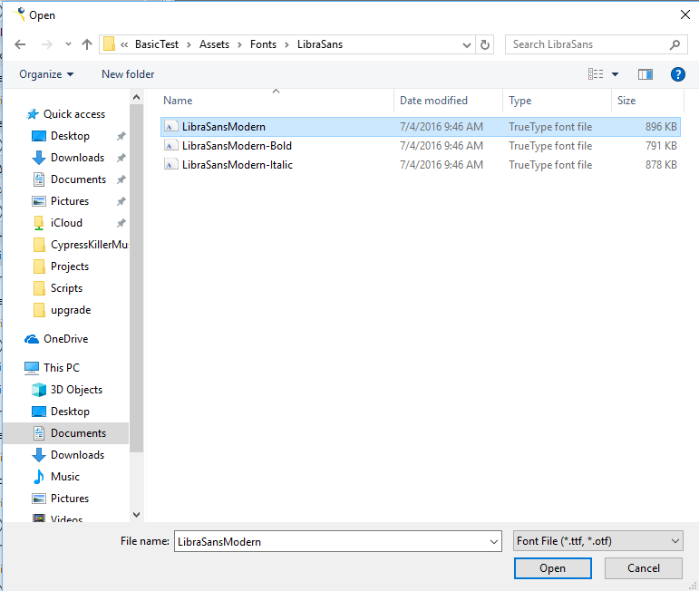
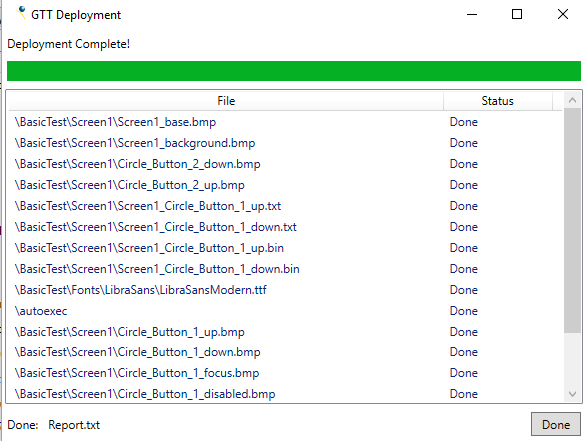
Once that is done press “Deploy”, and I get Success!
Now that I have the project built I need to wire the whole mess together. I am going to use a CY8CKIT-044. This development kit has a PSoC4200M. Although the project is using a PSoC6, I didnt have any level translators at my house (bad Alan) and I wanted to get going … so I used the 5V tolerant PSoC 4. [note: it turns out that the MCU used on the display has 5V tolerant serial I/Os but is a 3.3v MCU so I could have used it directly on the PSoC 6 without this work around] On the far left of the development kit, right next to the USB is the KitProg connector. This connector has an I2C Master and a UART Bridge. In addition I can connect the I2C pins to PSoC, the Display and the Bridge. Here is the schematic for the whole mess.
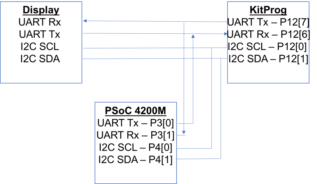
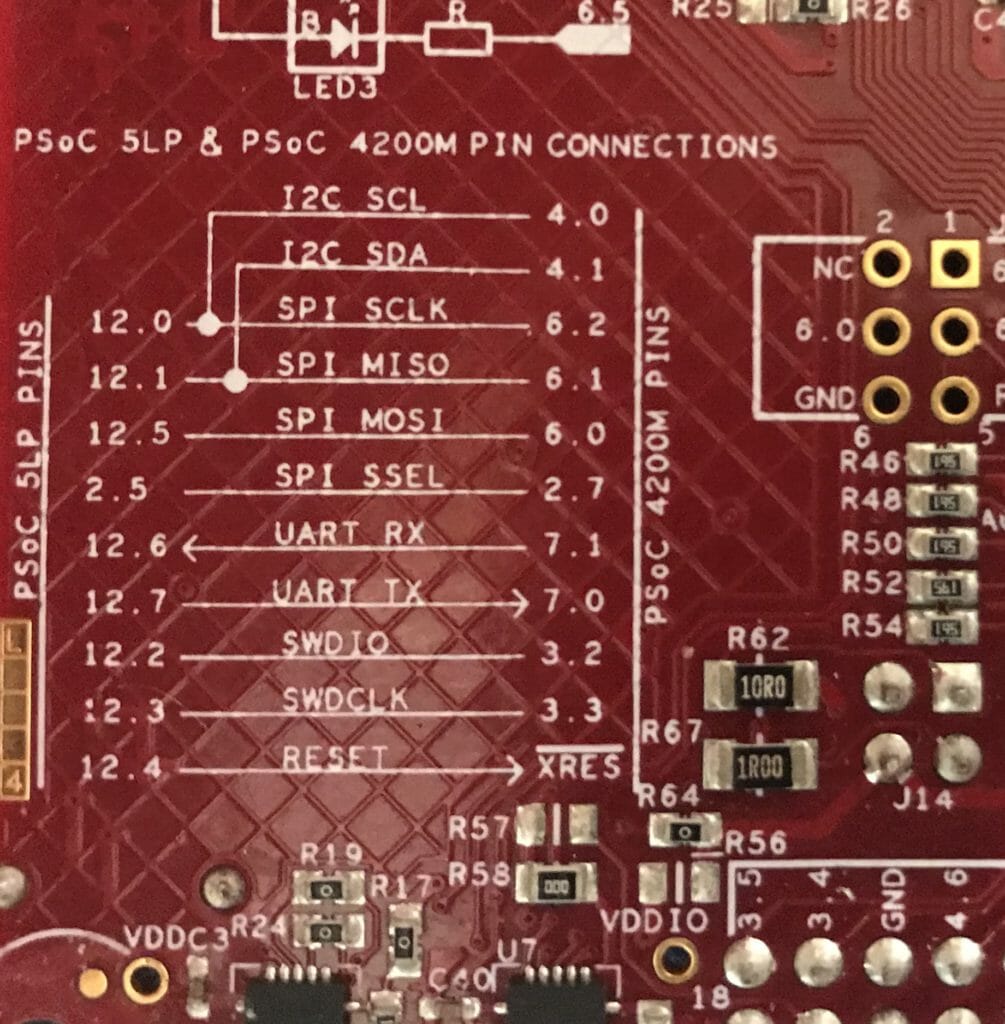
When you look on the back of the CY8CKIT-044 you can see the same wiring diagram on the silkscreen.
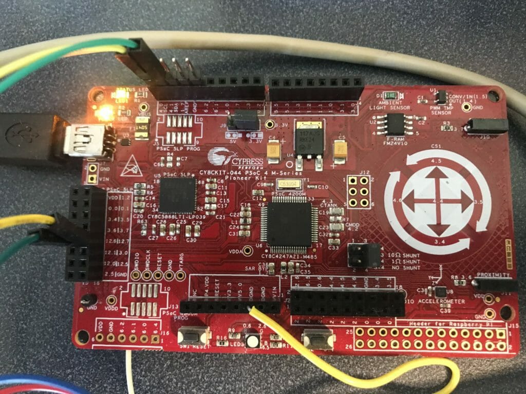
Here is a picture of the development kit. You can see the top green/yellow wires go to P40/P41 (that is the I2C Bus) and the other green/yellow set goes to P12[6] and P12[7] that is the KitProg UART. I suppose I should have used different colors for I2C and UART… oh well.
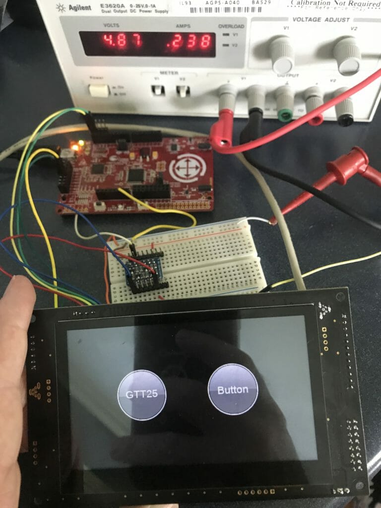
And finally the whole mess.
GTT43A Protocol 2.0
They way that the system works is you can send a command data packet to the display via one of the serial interfaces and then if there is a response required, it will respond with a response data packet. In addition when some event occurs on the display (like a touch screen button being pressed) it will send you a response data packet.
There are two GTT Protocols, one called 2.0 and one called 2.5. First the 2.0 protocol. You send messages in the GTT2.0 command data packet format. That format is simple:
- 254 – 1 byte
- Message ID (look in the manual for all of the legal message codes) – 1 byte
- Optional data 0-n bytes
If there is a required response, the screen will respond with a data packet in the following format
- 252 – 1 byte
- Message ID – 1 byte
- Length MSB – 1 byte
- Length LSB – 1 byte
- Optional Data – 0–>65535 bytes
The total length of the response will be (length msb) << 8 | length lsb – big endian.
For example a command with no optional data …. like reset will look like this { 252, 1 }. [obviously dont send the braces or the comma]
A command with some optional data is “Set Backlight Brightness”. If you want the brightness set to 23% you would send is {252, 153, 23}.
An example of a command that will respond with a response data packet is “Get Module Type” where you would send {254, 55 } and the screen would respond with {252, 55, 00 02 147 01}. Here is the picture from the manual.

When you look at the picture above there are several things to be VERY careful about.
First, the Matrix Orbital people appear to think in decimal not hex. So they show you {252,55,00,02,147,01) instead of (0xFE, 0x37, 0x00, 0x02, 0x93, 0x01}. Notice that my GTT43A value is decimal 37633 which is also known as Hex 0x9301. I often found myself typing hex when I mean decimal and vice versa.
The second thing to be careful about is that they send values in big endian… so if you are using an ARM processor be aware as ARM is almost always little endian.
The third thing to be careful about is that the length parameter in the message is always 16-bit Big Endian even though the documentation often shortens this to “Length”
Lastly, if they send you a 16-bit value it will show up as big endian, and they will probably show it to you in decimal (like table 14 above). Which can look kinda weird in decimal as it is two bytes.
GTT43A Protocol 2.5
As I worked on understanding what the screen is doing, I noticed that I was getting message codes that were not documented in the GTT2.0 Manual. For example when you press a button you will get {252,235,0,5,21,0,0,1,1}. When you look at this packet you can recognize the 252… and the message code 235 … and the length seems to make sense 5 … but the rest of the message is less clear.
So I called technical support, which is excellent, and Daniel agreed to send me a prerelease of the new manual. When you look at the manual you will find:
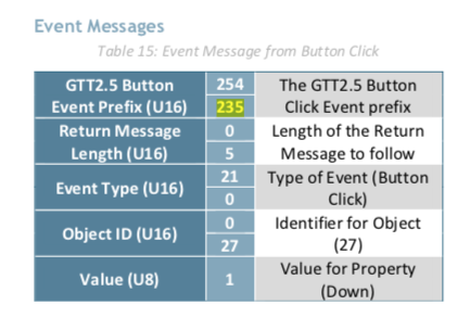
Which makes good sense as I pressed a button, and the object ID was “1”. The pre release version of the manual that I got seems to be missing information, but Im hopeful they will get it done and released soon. But for now, I can work with it. If you need a copy of the manual you will need to contact them directly.
GTT Support Tool
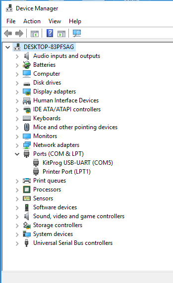
When you install GTT Designer, it will also install a program called the GTT Support Tool. This tool will allow you to send and receive GTT messages to/from the screen. I have the screen attached to the UART on the KitProg Serial bridge (with jumper wires). This means I will see the screen in the Device Manger under the Ports->KitProg (see the COM5)
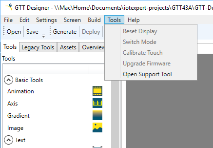
You can run the GTT Support Tool from the Start menu or from the Tools menu on the GTT Designer.
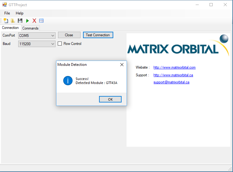
When the tool starts you can pick out which ComPort to talk to and setup the Flow Control (meaning use or not CTS/RTS). The KitProg on the 4200M does not have the CTS/RTS so you need to disable it or things will not work.

When you press the “Test Connection” it will send a message via the UART/ComPort and wait for a response. I am not sure, but I suspect that it is sending a “Get Module” command. In the picture below you can see that I got both the send and the receive message to work.
I was struggling over the weekend to get the communication to work correctly. Specifically I was not getting return messages. It turned out that the project that you build in the GTT Designer must have “Flow Control” turned off and the Default Channel set to Serial or the serial communication responses will not work. Remember you can set this on the “Display Settings”
You can also send the commands to set the communication channel and flow control, but I found it easier to get the project to the correct settings in the GTT Designer.
One you have a functional connection you can click on the “Commands” tab. On the left of the screen you will see a list of commands (well… actually on GTT2.0 commands). On the right side of the screen you will see your “script”, which obviously starts blank.

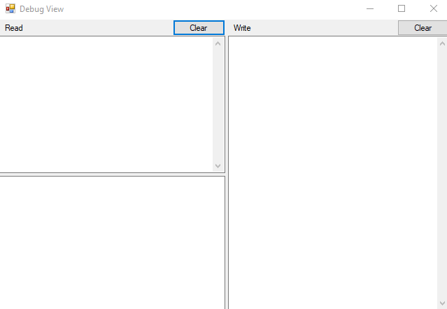
The first thing that you should do is press the little split screen button just to the right of the red “X”. When you do this it will bring up a new window that will show what is sent, and what is received. Obviously it starts blank.
Now you can double click on a command, like “Get Module Version” and it will bring up the command. When you press “OK” it will add it to the script. You CAN change the command and it will add it the script (but with a misleading name)
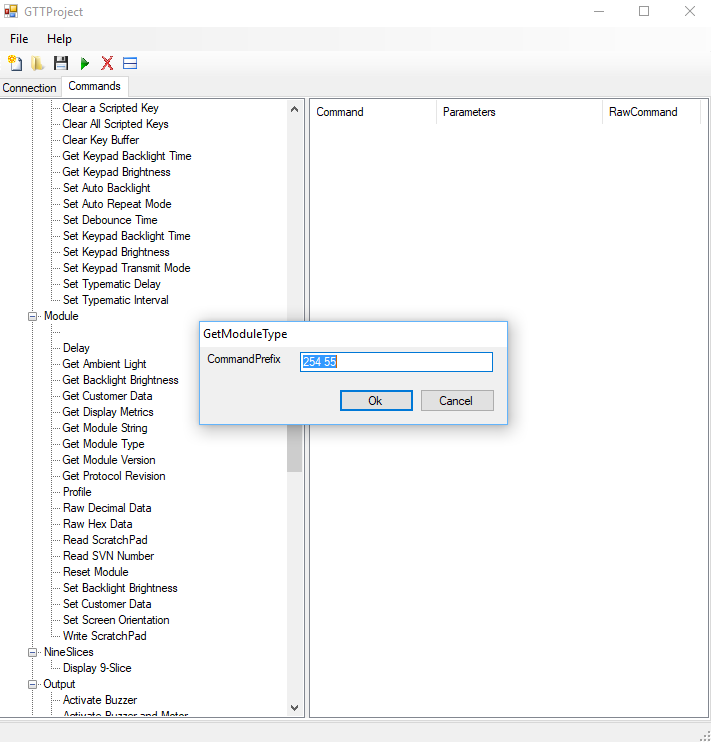
Here is what the window looks like after I add the “Get Module Type” command.

In order to Run the command, you need to click in the script window and then press the green run button. If you have not clicked in the script window it will not run. Once you have run the command your viewer window will look like this.
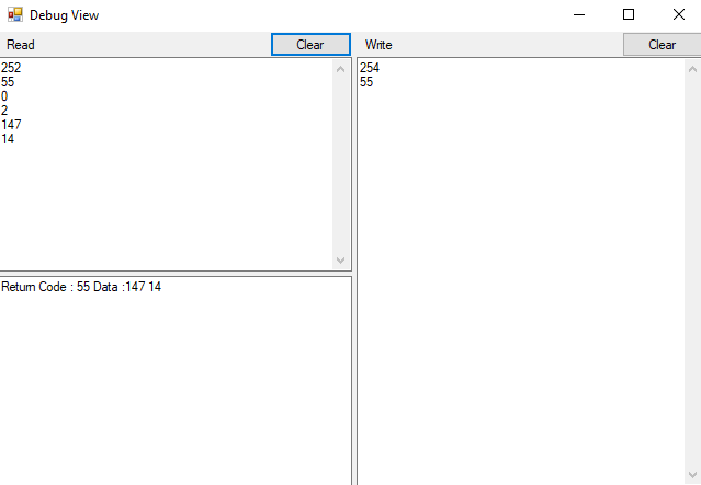
In the window above you can see that I wrote to the serial port a {254,55} and the screen responded {252,55,0,2,147,14}. When you decode this message don’t forget that the data above is in decimal. In this the example the message the 147,14 is actually 0x930E which is 37646. Unfortunately 37646 is not documented in the GTT 2.0 protocol manual (but my screen is a GTT43A).
Another cool thing that that happens in the Debug view is that it shows events that are initiated from the screen. For instance in the picture below I pressed the “GTT25” button from my example project. It show the button press and the button release.

Bridge Control Panel
For my real project I want to interact with the GTT43A via I2C. For this kind of thing I always like to use the Bridge Control Panel first. I have written a bunch of articles about using BCP to debug. This allows me to act as an I2C Master and see how the device acts as a slave. The first thing that I do is press “List Devices” on the BCP. It shows me that there are a number of things connected to the I2C bus.
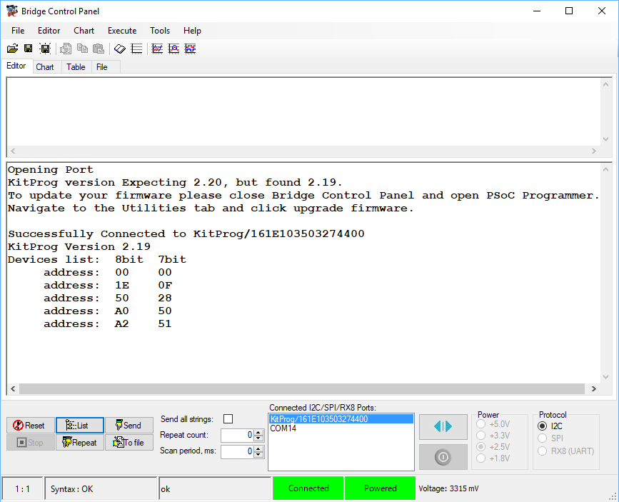
You might recall that from the Display Settings that the default I2C address is 80.
That 80 is also known as 0x50 (here we go with the Hex / Decimal thing again). Moreover that 80 (0x50) is an 8-Bit address, in other words shifted left 1 from the 7-bit address of 0x28.
After I verified that the screen was attached to the bridge control panel. The next thing to do was to set the default communication via I2C. Here is the section of the documentation
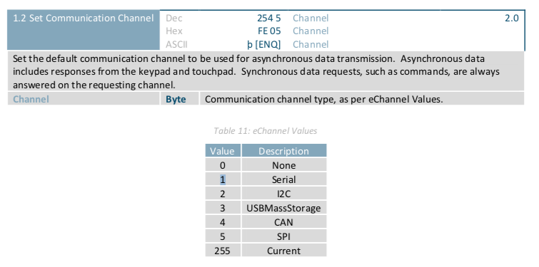
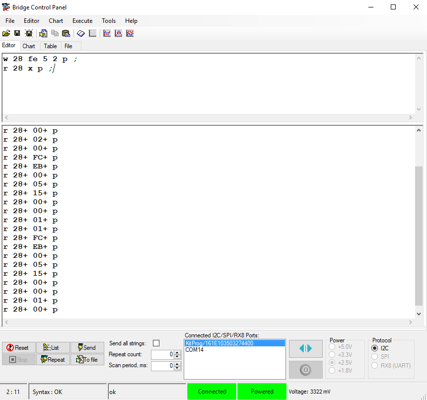
This means that I need to send {0xFE, ox05, 0x02}. When I send that command I get ACKs … good.

The next thing that I do is test to make sure that the legacy button is working correctly. When I press it and then read some bytes I get
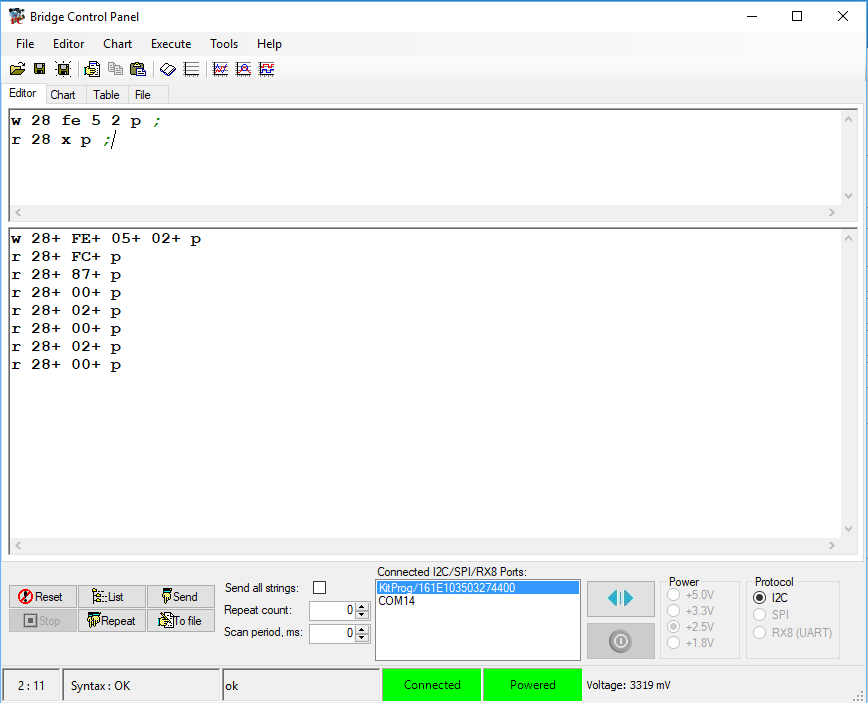
Then I press the GTT 25 Button and get {FC,EB,00,05,15,00,00,01,01} and then {FC,EB,00,05,14,00,00,01,00} in other words a press of button ID 1 and then a release of button ID 1.
Now that we understand the command protocol and we know how to talk to the screen, in the next article Ill talk about GTT Scripts.
You can "git" these projects from https://github.com/iotexpert/GTT43A And the driver library from https://github.com/iotexpert/GTT-Client-Library
Title
Matrix Orbital GTT43: A Cool Display
Matrix Orbital GTT43A: Serial Interface
Matrix Orbital GTT43A: GTT Scripts
Matrix Orbital GTT43A: A PSoC 4 Interface
Matrix Orbital GTT43A: Debugging the I2C
Matrix Orbital GTT43A: GTT Driver Library - Part 1
Matrix Orbital GTT43A: GTT Driver Library - Part 1
Matrix Orbital GTT43A: PSoC 6 using RTOS and the GTT Driver Library
No comment yet, add your voice below!