Mouser Bluetooth Mesh: L4 Integrating the Modus Toolbox Code Examples

How To Design With Bluetooth Mesh


You can "git" a workspace will all of these files at https://github.com/iotexpert/MouserVTWBluetoothMesh or git@github.com:iotexpert/MouserVTWBluetoothMesh.git

Summary

In this lesson I will show you how to find and use code examples.  I’ll then provision a motion sensor into my Bluetooth Mesh network and test.  Here are the steps:

  1. How to Find the Code Examples
  2. How to Import the Code Examples
  3. Explore the Code Examples
  4. How to Use a Code Example
  5. Provision the Motion Sensor Into the Network
  6. Test the Motion Sensor

How to Find the Code Examples

In the ModusToolbox Quick Panel pick “Search Online for Code Examples”

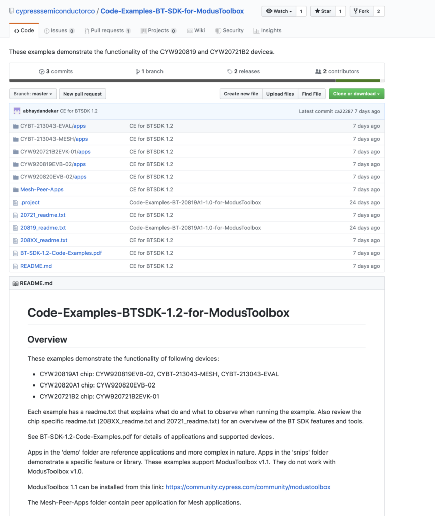
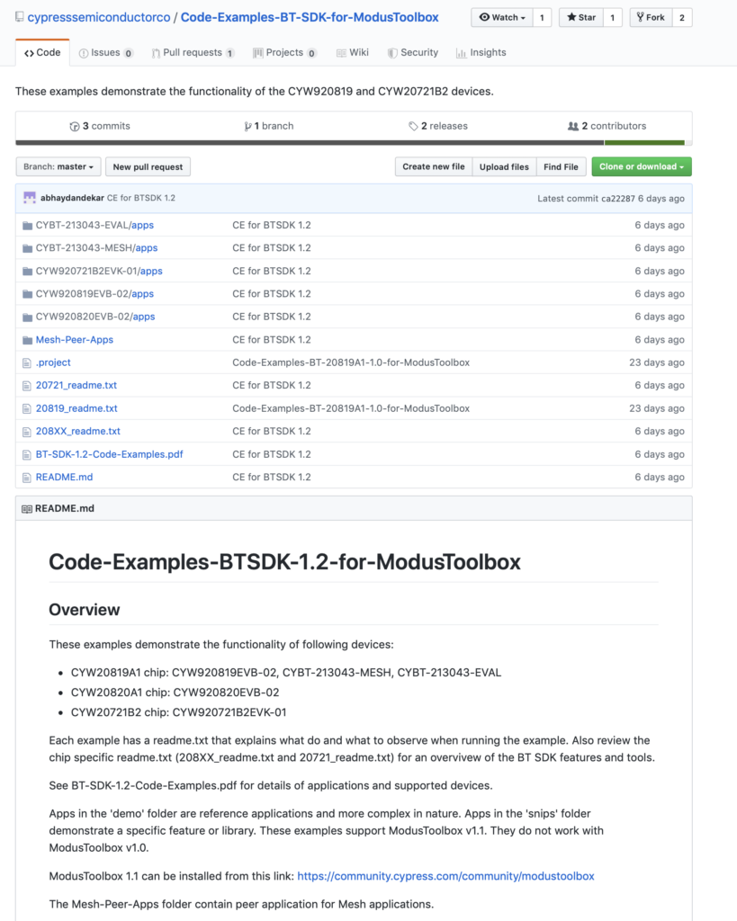
You will find yourself in a web browser on the cypressemiconductorco GitHub site.

Click on the link “Bluetooth SDK Examples”

You can look around on the website at the examples.  Or …

How to Import the Code Examples

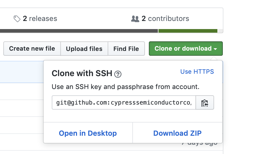
Click the “Clone or download” button.  This will give you this window which has the SSH or HTTPS address of the site.

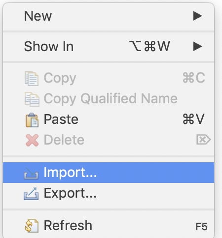
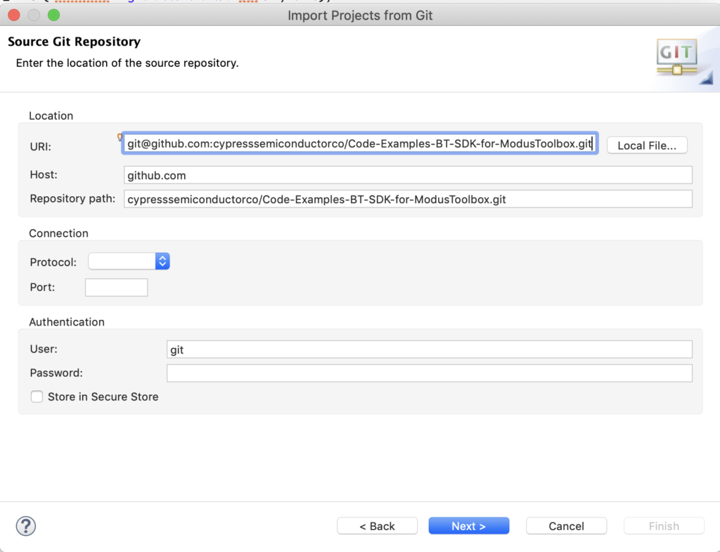
Copy the location of the github repo “git@github.com:cypresssemiconductorco/Code-Examples-BT-SDK-for-ModusToolbox.git”.  Then go back to the Workspace Explorer.  Right click and select “Import…”

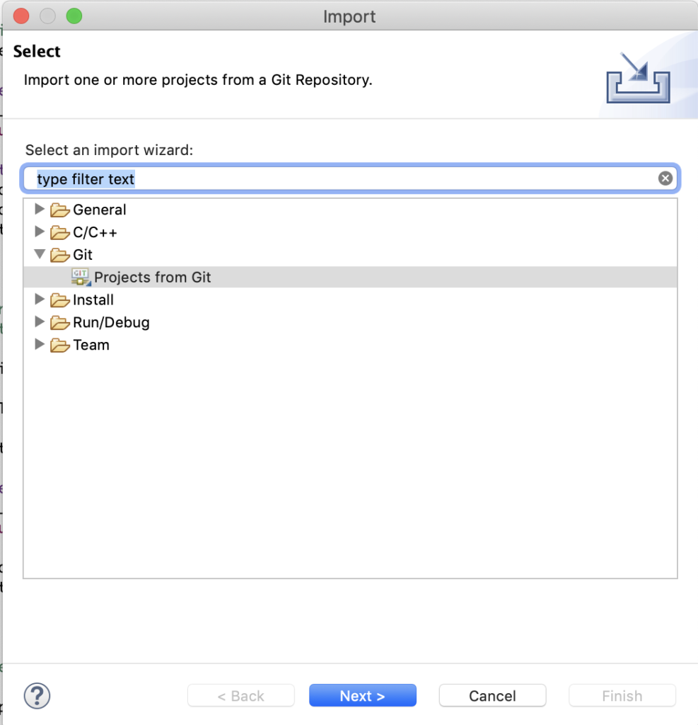
Choose Git–>Projects from Git

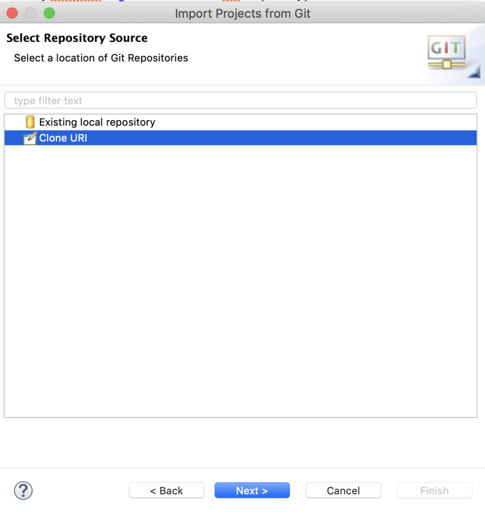
Select “Clone URI” (so you can get the examples from the Internet)

Paste in the URI (which you copied from the web browser) Then press Next–>

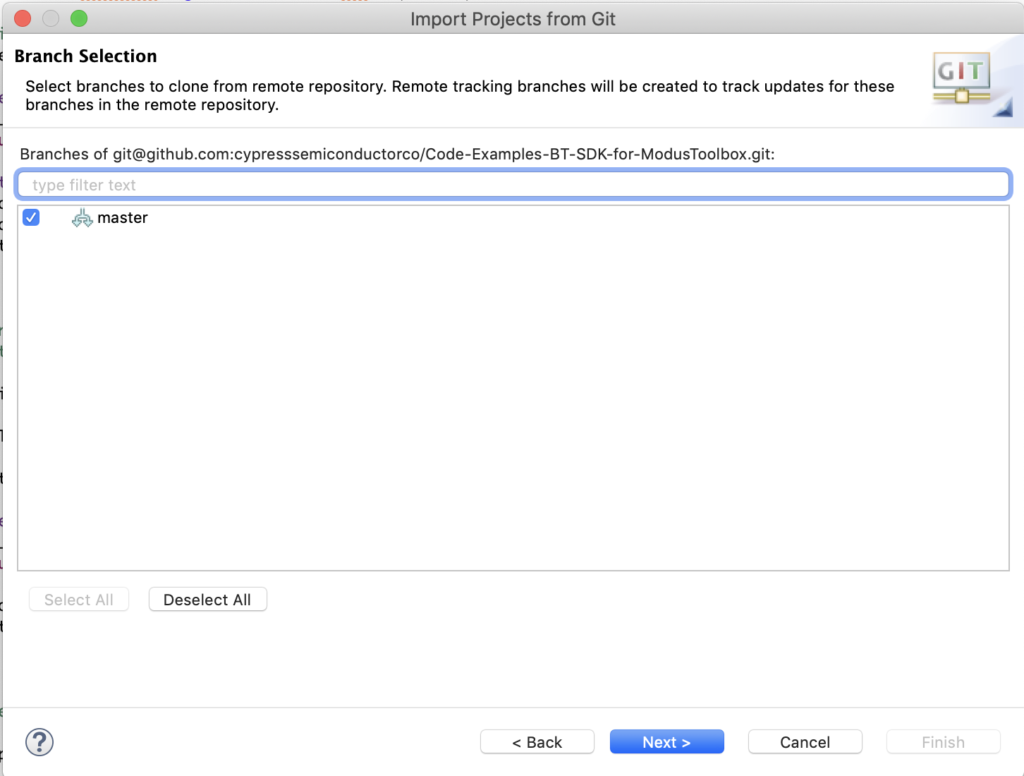
Pick out the master branch.

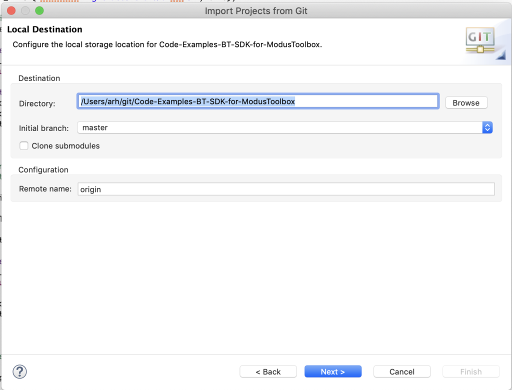
You will now need to tell Eclipse where you want it to save the repository on your local machine.  I let it select the default location and press Next –>

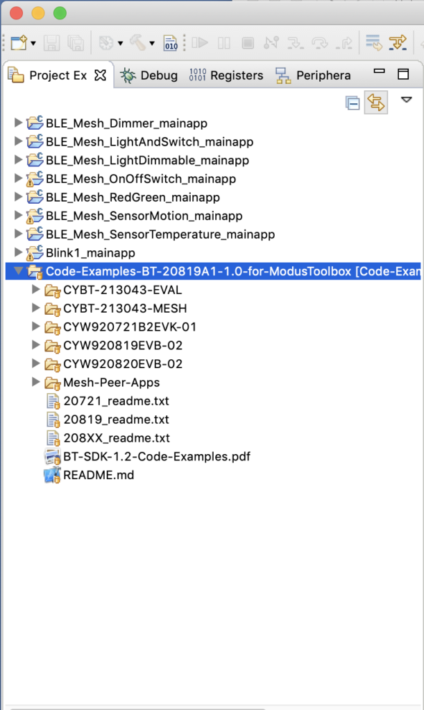
To make things easy, you can then import that directory full of goodness into your Workspace.  An excellent developer I know says that Code is all of the documentation you need.  Which means that it is nice to be able to browse the code in a good editor.

Explore the Code Examples

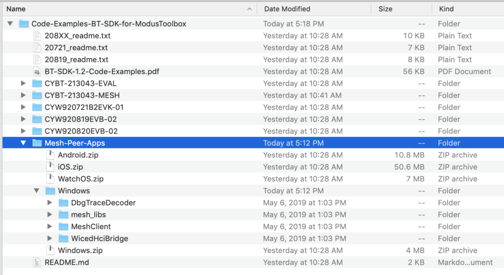
Now you should have the folder “Code-Examples-BT-20819A1-1.0-for-ModusToolbox” inside of your Workspace.

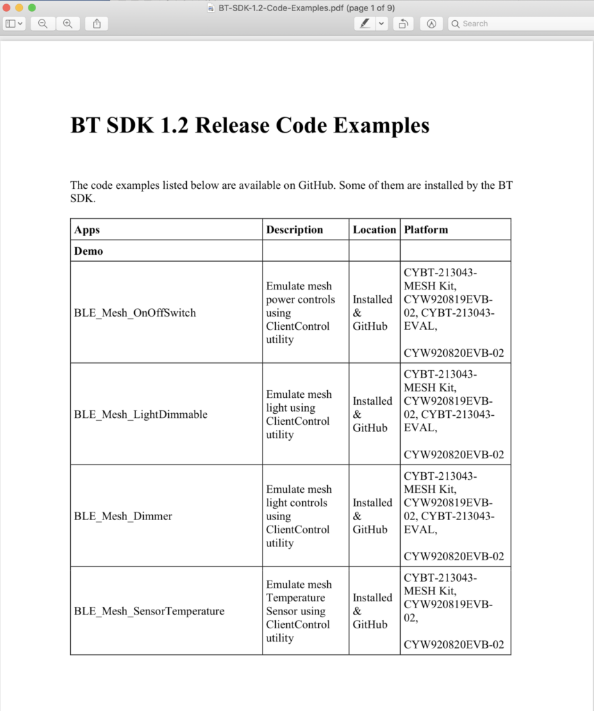
If you double click the “BT-SDK-1.2-Code-Examples.pdf” you will get a description of them all

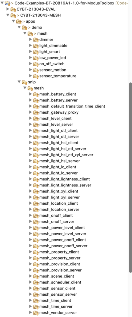
You can walk through them using the Workspace Explorer.  Notice that we created examples for many of the Bluetooth Mesh Models.

Example Peer Apps

We had a problem with Peer Apps in the SDK1.2 release and this was fixed by adding the Peer Apps to the Example Projects.

How to use a Code Example

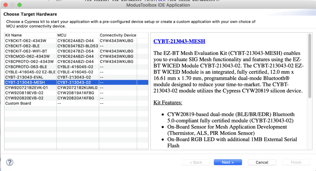
To create a project from one of the code examples, start by choosing “File->New->ModusToolbox IDE Application”

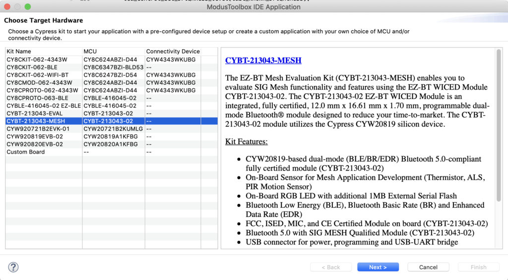
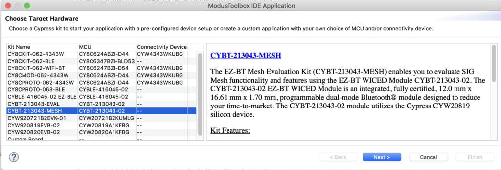
Pick the correct development kit “CYBT-213043-MESH”

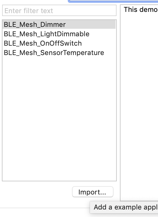
Select “Import”

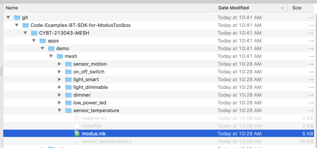
Navigate to the file “modus.mk” of the example you want.  This will be in the directory on your computer where you cloned the GitHub repository.

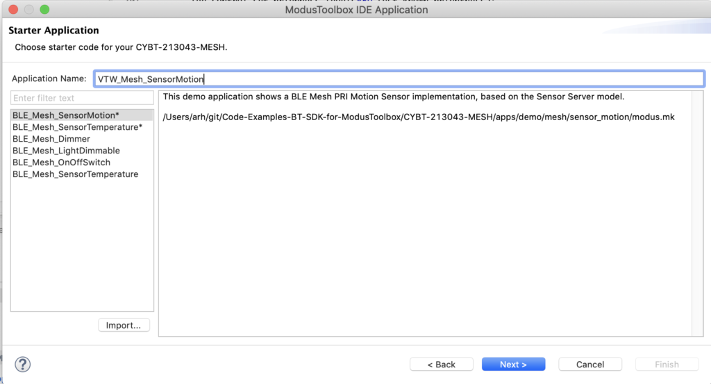
After doing the Import you will have that example as a Starter Application.  Notice that they have an asterisks beside the name.  Type the name of your application if you want to change it.  In this case I pick “VTW_Mesh_SensorMotion”.  Then press “Next->”

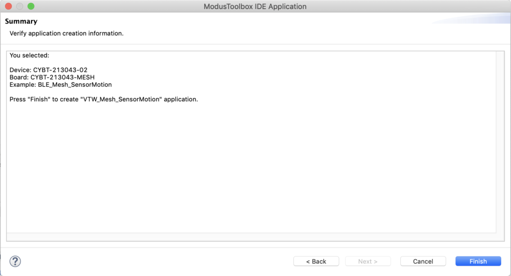
Click “Finish”

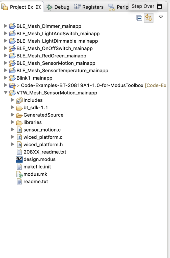
Now you will have the application in the Workspace.

You can now press “VTW_Mesh_SensorMotion Build + Program”

And you will end up with this in your console after sweet Success!!!

Provision the Motion Sensor into the Network

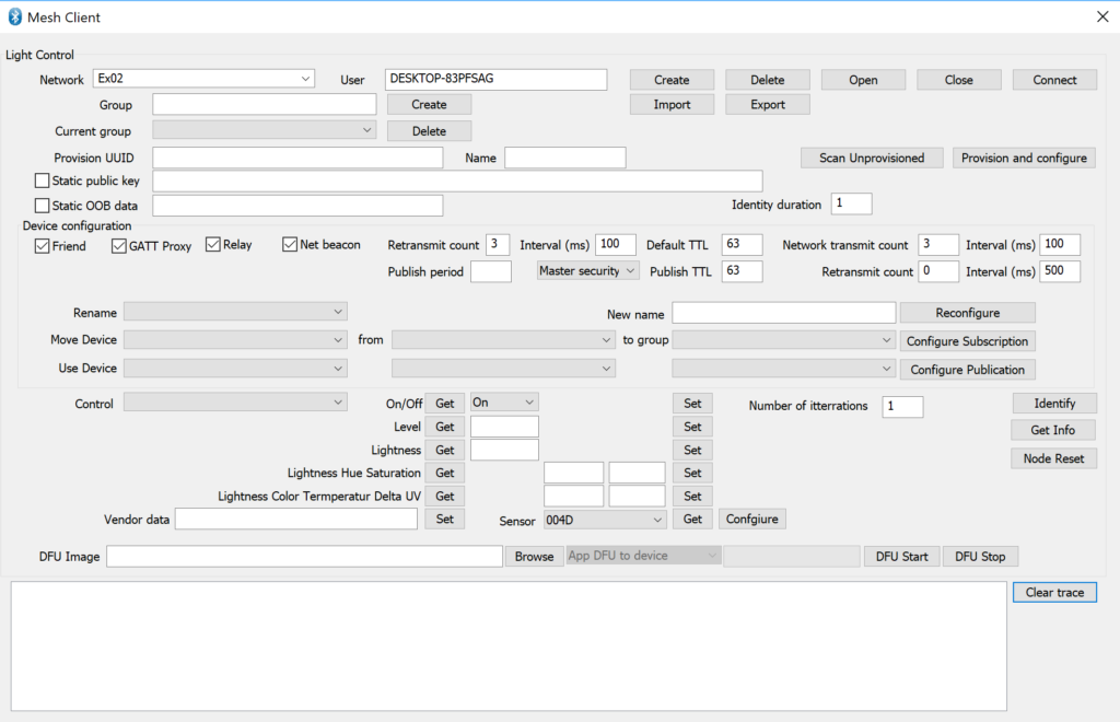
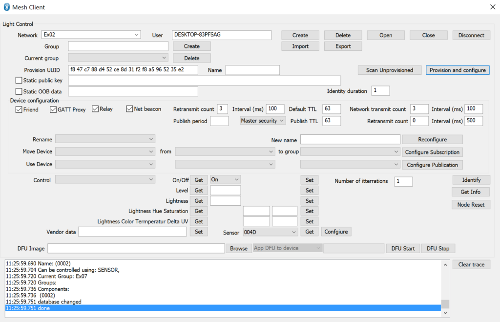
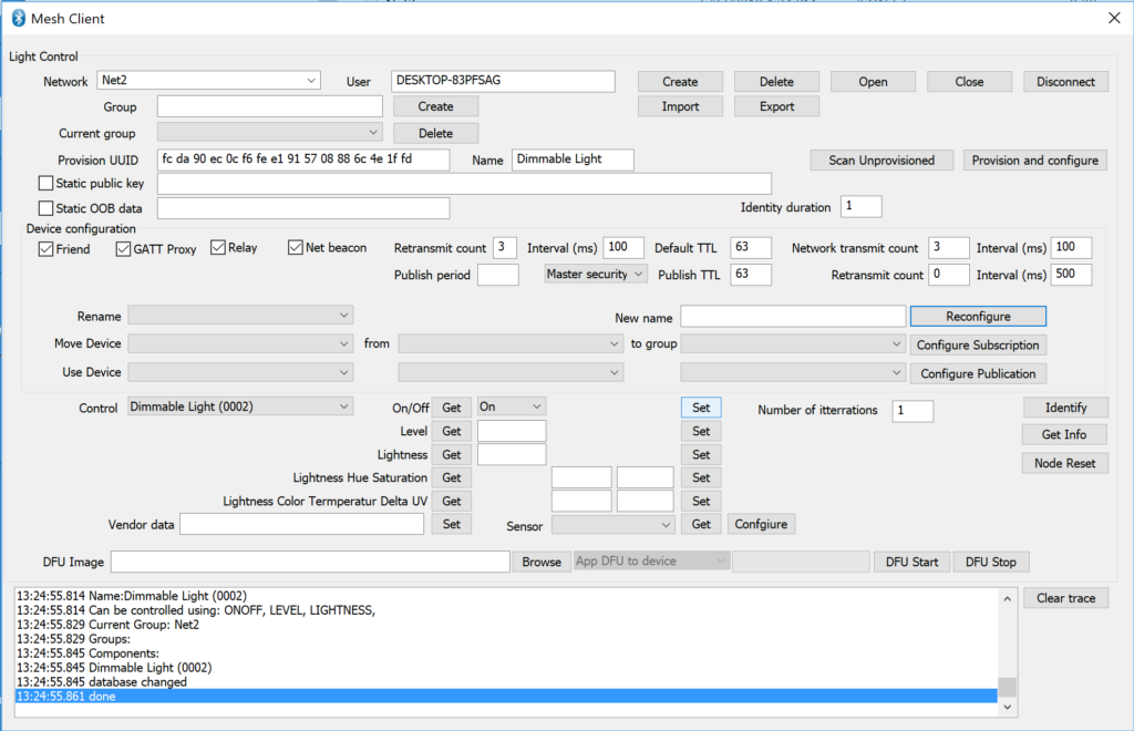
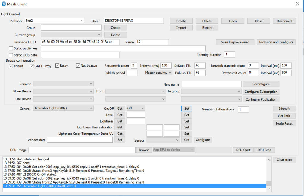
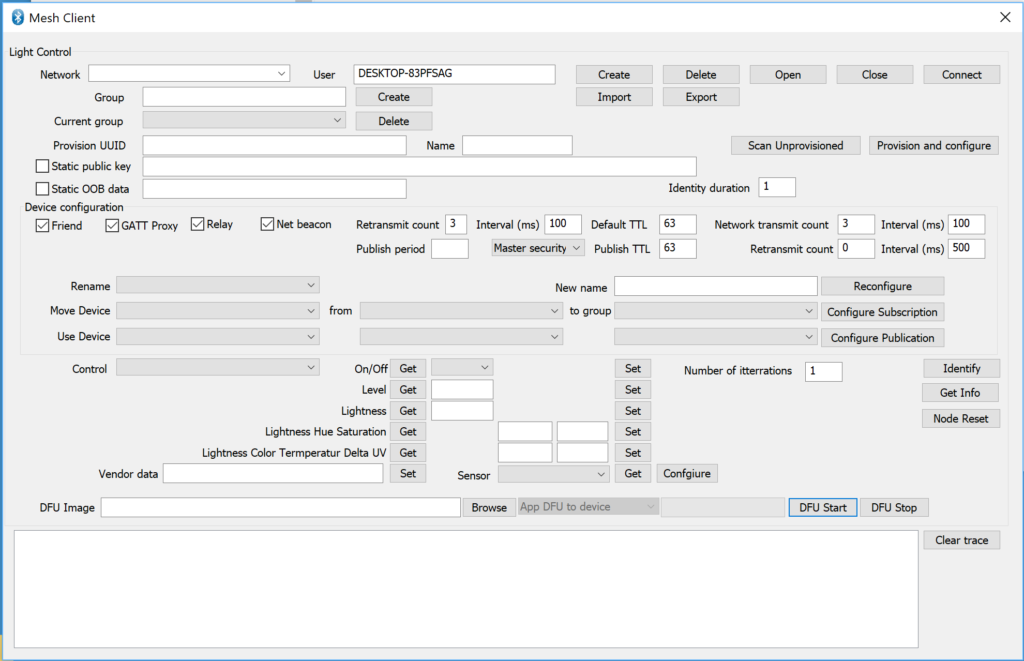
I now have a board programmed with the Motion Sensor Application.  Seems like that it will be a good idea to provision it into the network and see if it is doing anything.  Press “Scan Unprovisioned”.

Once I see my device, I’ll stop scanning and then press “Provision and configure”.  After a minute our tool will tell you that it is done!

Test the Motion Sensor

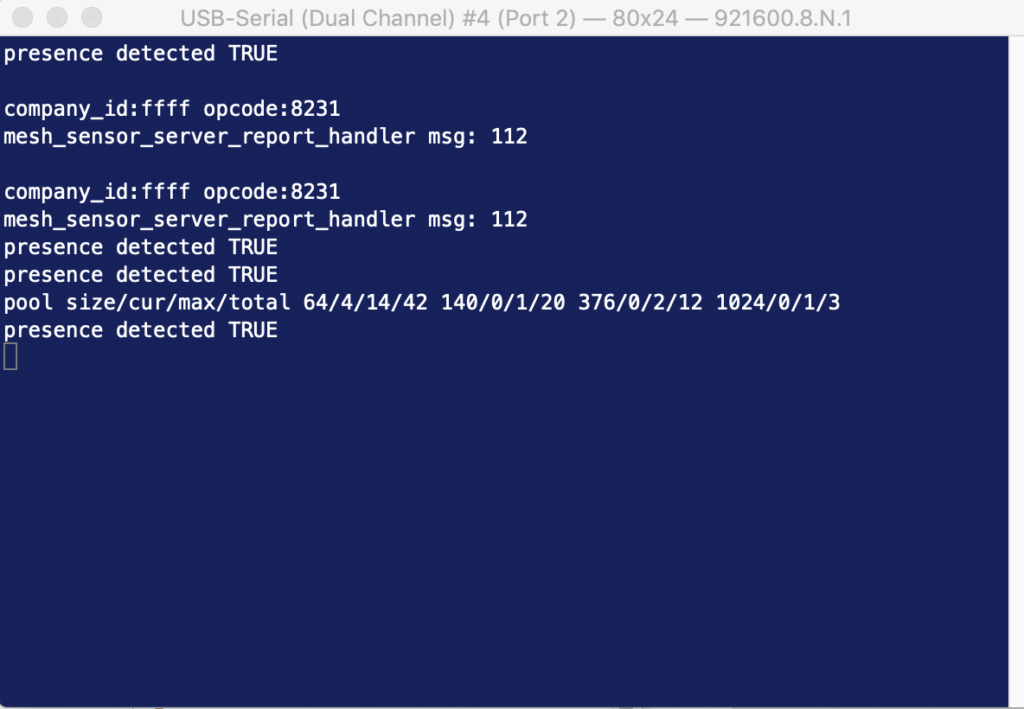
You can request the state of the sensor by clicking “Control” and then picking the motion sensor.  Now press the “Get” button for the sensor and you will see that the sensor is graced with my presence.

Each time I click “Get” you can see the transaction happening on the development kit.

Mouser Bluetooth Mesh: L3 Making a Light Switch Using the Example Code

How To Design With Bluetooth Mesh


You can "git" a workspace will all of these files at https://github.com/iotexpert/MouserVTWBluetoothMesh or git@github.com:iotexpert/MouserVTWBluetoothMesh.git

Summary

In the first several lessons I showed you how to build a BLE Mesh Network using the Cypress Android App and the Windows Application.  I don’t know about you, but even though I live twenty years back in time in Kentucky I still have light switches.  In this lesson Ill show you how to add a light switch to your network.  And then we will have a good look a the code because we have run enough demo projects.

Given that I have a working network from the last lesson I will just add the switch to that network.  Meaning, I will use the Mesh Client to provision in the new switch.

For this exercise we will:

  1. Create the VTW_MeshOnOffSwitch Project
  2. Provision and Configure the Switch
  3. Firmware Architecture
  4. Examine the Code

Create the VTW_MeshOnOffSwitch Project

Start a new project with File–>New–>ModusToolbox IDE Application

Pick out the CYBT-213043-MESH hardware.

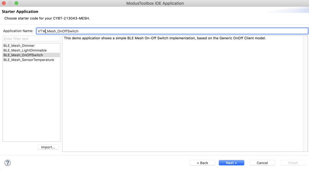
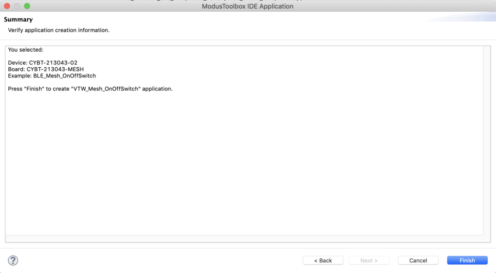
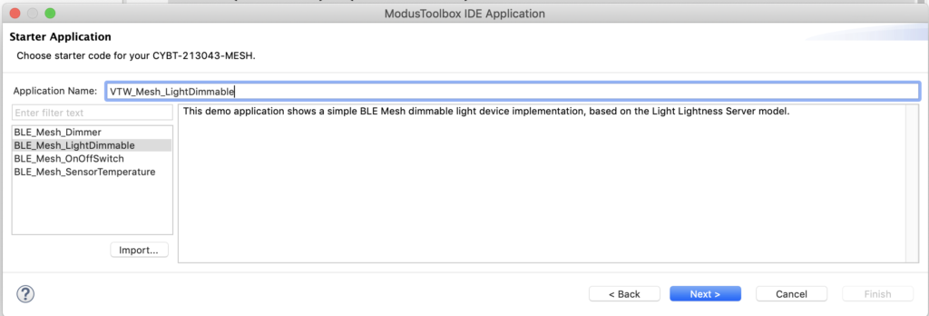
I will use the BLE_Mesh_OnOffSwitch starter application.  Notice that I named it “VTW_Mesh_OnOffSwitch”

Now press Finish to create the application in your workspace.

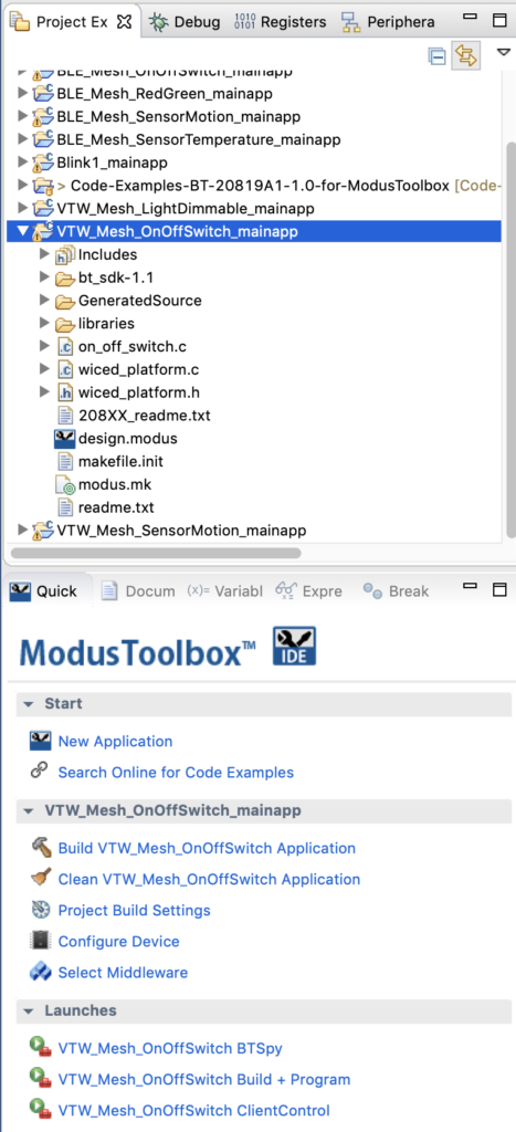
Now your Project Explorer should look like this.  Notice that in the quick panel there are the launches for this application.

So, press “VTW_MeshOnOffSwitch Build + Program”

Provision and Configure the Switch

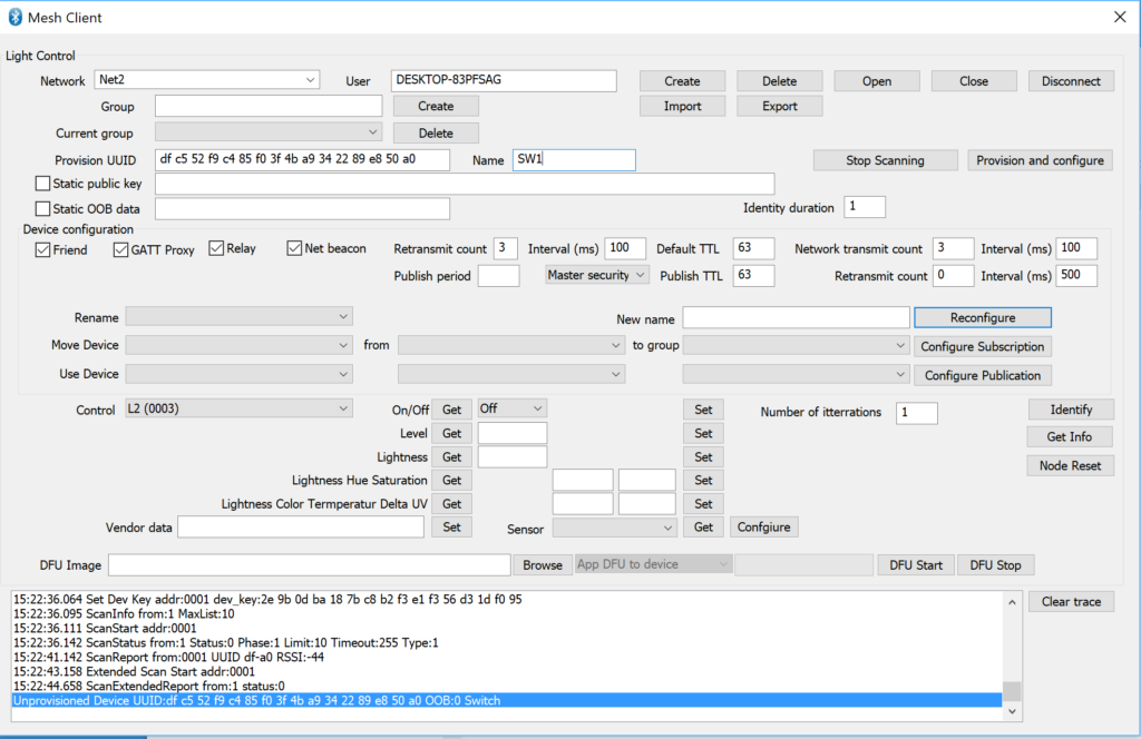
Go back to the Mesh Client application.  Just as before you can add the Switch to the network by scanning for unprovisioned BLE Mesh Nodes.  When the node shows up, give it a name of SW1 and then press “Provision and configure”

After a while, your trace window will indicate success via the ever informative “done” message.

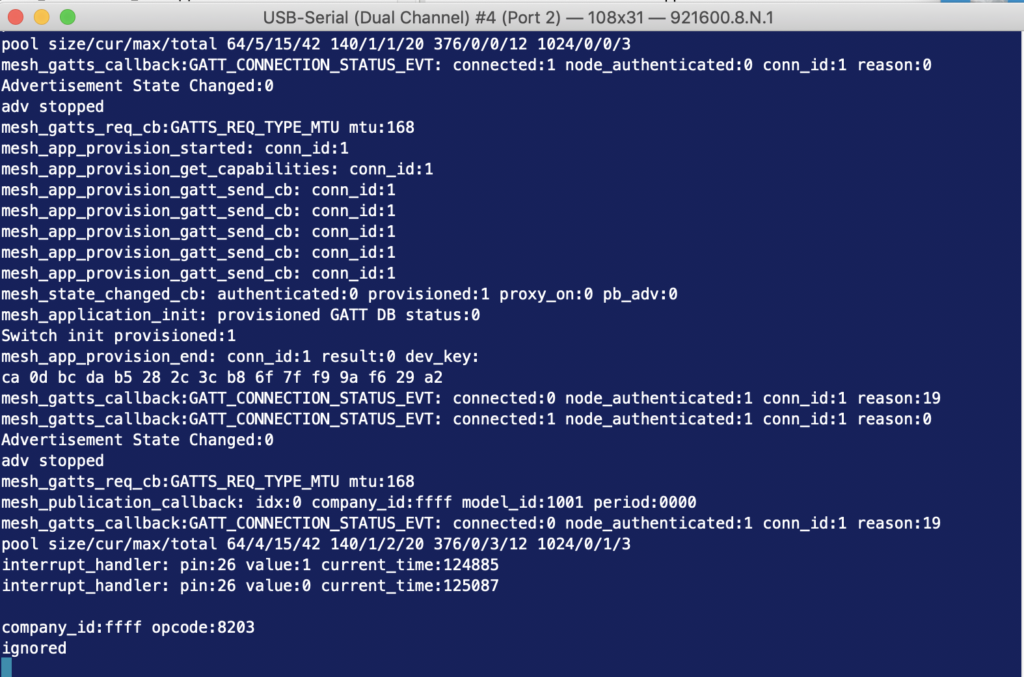
If you have a serial terminal attached to the development kit you will see what happens during the provision/configuration process.

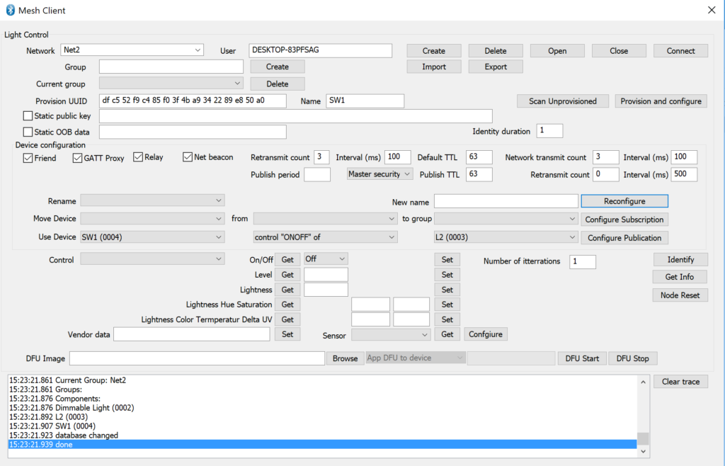
Now test the button on your new Light Switch and notice that both LEDs turn on (both Dimmable and L2).  You can configure the Switch to control only L2 if you want.  On the “Use Device” drop down pick “SW1 (0004)” then select control “ONOFF” and pick the switch “L2”.

After applying the change you can see that switch only controls L2.  You can then switch it to “Dimmable” to control the other LED.

Firmware Architecture

Examine the Code

A Cypress Bluetooth Mesh project has several basic sections  Specifically you must configure:

  1. Elements & Models
  2. Mesh Config
  3. Application Function Pointers
  4. mesh_app_init

Plus for the switch application, you will need to configure the button management code (what happens when the button is pushed).

    Elements and Models

    The “Element” is a fundamental unit of thingness in a BLE Mesh.  For instance in the projects we have looked at, the LEDs are represented by an Element, and the switch is represented by another element.  Each element will have one or more models that represent the functionality of the element.  For instance, in a switch you will have a “WICED_BT_MESH_MODEL_ONOFF_CLIENT”.   If you look at on_off_switch.c you will see that we first define an array of models.  Then we define an array of elements.  The array mesh_element1_models will be associated with the the first element.

    wiced_bt_mesh_core_config_model_t   mesh_element1_models[] =
    {
        WICED_BT_MESH_DEVICE,
        WICED_BT_MESH_MODEL_ONOFF_CLIENT,
    };
    #define MESH_APP_NUM_MODELS  (sizeof(mesh_element1_models) / sizeof(wiced_bt_mesh_core_config_model_t))
    
    #define ONOFF_SWITCH_ELEMENT_INDEX   0
    
    wiced_bt_mesh_core_config_element_t mesh_elements[] =
    {
        {
            .location = MESH_ELEM_LOC_MAIN,                                 // location description as defined in the GATT Bluetooth Namespace Descriptors section of the Bluetooth SIG Assigned Numbers
            .default_transition_time = MESH_DEFAULT_TRANSITION_TIME_IN_MS,  // Default transition time for models of the element in milliseconds
            .onpowerup_state = WICED_BT_MESH_ON_POWER_UP_STATE_RESTORE,     // Default element behavior on power up
            .default_level = 0,                                             // Default value of the variable controlled on this element (for example power, lightness, temperature, hue...)
            .range_min = 1,                                                 // Minimum value of the variable controlled on this element (for example power, lightness, temperature, hue...)
            .range_max = 0xffff,                                            // Maximum value of the variable controlled on this element (for example power, lightness, temperature, hue...)
            .move_rollover = 0,                                             // If true when level gets to range_max during move operation, it switches to min, otherwise move stops.
            .properties_num = 0,                                            // Number of properties in the array models
            .properties = NULL,                                             // Array of properties in the element.
            .sensors_num = 0,                                               // Number of sensors in the sensor array
            .sensors = NULL,                                                // Array of sensors of that element
            .models_num = MESH_APP_NUM_MODELS,                              // Number of models in the array models
            .models = mesh_element1_models,                                 // Array of models located in that element. Model data is defined by structure wiced_bt_mesh_core_config_model_t
        },
    };
    

    Mesh Config

    The mesh config structure handles the basic setup for the Cypress Bluetooth Mesh.  This structure is loaded in by the stack when it starts.

    wiced_bt_mesh_core_config_t  mesh_config =
    {
        .company_id         = MESH_COMPANY_ID_CYPRESS,                  // Company identifier assigned by the Bluetooth SIG
        .product_id         = MESH_PID,                                 // Vendor-assigned product identifier
        .vendor_id          = MESH_VID,                                 // Vendor-assigned product version identifier
        .firmware_id        = MESH_FWID,                                // Vendor-assigned firmware version identifier
        .replay_cache_size  = MESH_CACHE_REPLAY_SIZE,                   // Number of replay protection entries, i.e. maximum number of mesh devices that can send application messages to this device.
    #if defined(LOW_POWER_NODE) && (LOW_POWER_NODE == 1)
        .features           = WICED_BT_MESH_CORE_FEATURE_BIT_LOW_POWER, // A bit field indicating the device features. In Low Power mode no Relay, no Proxy and no Friend
        .friend_cfg         =                                           // Empty Configuration of the Friend Feature
        {
            .receive_window = 0,                                        // Receive Window value in milliseconds supported by the Friend node.
            .cache_buf_len  = 0,                                        // Length of the buffer for the cache
            .max_lpn_num    = 0                                         // Max number of Low Power Nodes with established friendship. Must be > 0 if Friend feature is supported. 
        },
        .low_power          =                                           // Configuration of the Low Power Feature
        {
            .rssi_factor           = 2,                                 // contribution of the RSSI measured by the Friend node used in Friend Offer Delay calculations.
            .receive_window_factor = 2,                                 // contribution of the supported Receive Window used in Friend Offer Delay calculations.
            .min_cache_size_log    = 3,                                 // minimum number of messages that the Friend node can store in its Friend Cache.
            .receive_delay         = 100,                               // Receive delay in 1ms units to be requested by the Low Power node.
            .poll_timeout          = 36000                              // Poll timeout in 100ms units to be requested by the Low Power node.
        },
    #else
        .features           = 0,                                        // no, support for proxy, friend, or relay
        .friend_cfg         =                                           // Empty Configuration of the Friend Feature
        {
            .receive_window        = 0,                                 // Receive Window value in milliseconds supported by the Friend node.
            .cache_buf_len         = 0,                                 // Length of the buffer for the cache
            .max_lpn_num           = 0                                  // Max number of Low Power Nodes with established friendship. Must be > 0 if Friend feature is supported. 
        },
        .low_power          =                                           // Configuration of the Low Power Feature
        {
            .rssi_factor           = 0,                                 // contribution of the RSSI measured by the Friend node used in Friend Offer Delay calculations.
            .receive_window_factor = 0,                                 // contribution of the supported Receive Window used in Friend Offer Delay calculations.
            .min_cache_size_log    = 0,                                 // minimum number of messages that the Friend node can store in its Friend Cache.
            .receive_delay         = 0,                                 // Receive delay in 1 ms units to be requested by the Low Power node.
            .poll_timeout          = 0                                  // Poll timeout in 100ms units to be requested by the Low Power node.
        },
    #endif
        .gatt_client_only          = WICED_FALSE,                       // Can connect to mesh over GATT or ADV
        .elements_num  = (uint8_t)(sizeof(mesh_elements) / sizeof(mesh_elements[0])),   // number of elements on this device
        .elements      = mesh_elements                                  // Array of elements for this device
    };
    

    Application Function Pointers

    The Bluetooth Mesh stack interacts with your program via functions that it runs when something is happening.  You can either accept the default behavior, or you can write your own function.

    /*
     * Mesh application library will call into application functions if provided by the application.
     */
    wiced_bt_mesh_app_func_table_t wiced_bt_mesh_app_func_table =
    {
        mesh_app_init,          // application initialization
        mesh_app_hardware_init, // hardware initialization
        NULL,                   // GATT connection status
        NULL,                   // attention processing
        NULL,                   // notify period set
        NULL,                   // WICED HCI command
        NULL,                   // LPN sleep
        NULL                    // factory reset
    };

    mesh_app_init

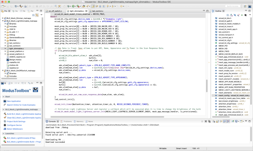
    The function mesh_app_init is called by the stack when the stack starts.  It is your opportunity to get things going.   In the “if” we setup information which makes it easier to see what is happening when you provision by adding that information to the scan response packet.

    The last thing we do in mesh_app_init function is initialize the onoff client model. This should be done for any models that your device uses. The model initialization functions can accept the name of a function that we want the stack to call when it receives messages from the network for that model. In this case, we don’t need to do anything in our firmware for onoff client messages, so we specify NULL.

    /******************************************************
     *               Function Definitions
     ******************************************************/
    void mesh_app_init(wiced_bool_t is_provisioned)
    {
    #if 0
        extern uint8_t wiced_bt_mesh_model_trace_enabled;
        wiced_bt_mesh_model_trace_enabled = WICED_TRUE;
    #endif
        wiced_bt_cfg_settings.device_name = (uint8_t *)"Switch";
        wiced_bt_cfg_settings.gatt_cfg.appearance = APPEARANCE_CONTROL_DEVICE_SLIDER;
    
    #if defined(LOW_POWER_NODE) && (LOW_POWER_NODE == 1)
        WICED_BT_TRACE("LPN Switch init provisioned:%d\n", is_provisioned);
    #else
        WICED_BT_TRACE("Switch init provisioned:%d\n", is_provisioned);
    #endif
    
        // Adv Data is fixed. Spec allows to put URI, Name, Appearance and Tx Power in the Scan Response Data.
        if (!is_provisioned)
        {
            wiced_bt_ble_advert_elem_t  adv_elem[3];
            uint8_t                     buf[2];
            uint8_t                     num_elem = 0;
    
            adv_elem[num_elem].advert_type = BTM_BLE_ADVERT_TYPE_NAME_COMPLETE;
            adv_elem[num_elem].len         = (uint16_t)strlen((const char*)wiced_bt_cfg_settings.device_name);
            adv_elem[num_elem].p_data      = wiced_bt_cfg_settings.device_name;
            num_elem++;
    
            adv_elem[num_elem].advert_type = BTM_BLE_ADVERT_TYPE_APPEARANCE;
            adv_elem[num_elem].len         = 2;
            buf[0]                         = (uint8_t)wiced_bt_cfg_settings.gatt_cfg.appearance;
            buf[1]                         = (uint8_t)(wiced_bt_cfg_settings.gatt_cfg.appearance >> 8);
            adv_elem[num_elem].p_data      = buf;
            num_elem++;
    
            wiced_bt_mesh_set_raw_scan_response_data(num_elem, adv_elem);
        }
    
        // This application does not check result of the transmission or status event from the
        // target device.  Initialize OnOff client library not registering the callback.
        wiced_bt_mesh_model_onoff_client_init(ONOFF_SWITCH_ELEMENT_INDEX, NULL, is_provisioned);
    }
    

    Button Management Code

    Now you just need to setup the button hardware in the mesh_app_hardware_init function to generate an interrupt when the button is pressed or released..

    void mesh_app_hardware_init(void)
    {
        /* Configure buttons available on the platform */
    #if defined(CYW20706A2)
        wiced_hal_gpio_configure_pin(WICED_GPIO_BUTTON, WICED_GPIO_BUTTON_SETTINGS(GPIO_EN_INT_BOTH_EDGE), WICED_GPIO_BUTTON_DEFAULT_STATE);
        wiced_hal_gpio_register_pin_for_interrupt(WICED_GPIO_BUTTON, button_interrupt_handler, NULL);
    #elif (defined(CYW20735B0) || defined(CYW20719B0) || defined(CYW20721B0))
        wiced_hal_gpio_register_pin_for_interrupt(WICED_GPIO_PIN_BUTTON, button_interrupt_handler, NULL);
        wiced_hal_gpio_configure_pin(WICED_GPIO_PIN_BUTTON, WICED_GPIO_BUTTON_SETTINGS, GPIO_PIN_OUTPUT_LOW);
    #else
        wiced_platform_register_button_callback(WICED_PLATFORM_BUTTON_1, button_interrupt_handler, NULL, GPIO_EN_INT_BOTH_EDGE);
        button_previous_value = platform_button[WICED_PLATFORM_BUTTON_1].default_state;
    #endif
    }

    The interrupt handler will call the function wiced_bt_mesh_model_onoff_client_set to publish the button pressed message.

    /*
     * Process interrupts from the button.
     */
    void button_interrupt_handler(void* user_data, uint8_t pin)
    {
        uint32_t value = wiced_hal_gpio_get_pin_input_status(pin);
        uint32_t current_time = wiced_bt_mesh_core_get_tick_count();
        uint32_t button_pushed_duration;
    
        if (value == button_previous_value)
        {
            WICED_BT_TRACE("interrupt_handler: duplicate pin:%d value:%d current_time:%d\n", pin, value, current_time);
            return;
        }
        button_previous_value = value;
    
        WICED_BT_TRACE("interrupt_handler: pin:%d value:%d current_time:%d\n", pin, value, current_time);
    
        if (value == platform_button[WICED_PLATFORM_BUTTON_1].button_pressed_value)
        {
            button_pushed_time = current_time;
            return;
        }
        // button is released
        button_pushed_duration = current_time - button_pushed_time;
        if (button_pushed_duration < 15000)
        {
            process_button_push(ONOFF_SWITCH_ELEMENT_INDEX);
        }
        else
        {
            // More than 15 seconds means factory reset
            mesh_application_factory_reset();
        }
    }
    
    void process_button_push(uint8_t element_idx)
    {
        static uint8_t onoff = 0;
        wiced_bt_mesh_onoff_set_data_t set_data;
    
        onoff ^= 1;
    
        set_data.onoff           = onoff;
        set_data.transition_time = WICED_BT_MESH_TRANSITION_TIME_DEFAULT;
        set_data.delay           = 0;
    
        wiced_bt_mesh_model_onoff_client_set(element_idx, &set_data);
    }


    Mouser Bluetooth Mesh: L2B Building a Mesh Network Using the Mesh Client

    How To Design With Bluetooth Mesh


    You can "git" a workspace will all of these files at https://github.com/iotexpert/MouserVTWBluetoothMesh or git@github.com:iotexpert/MouserVTWBluetoothMesh.git

    Summary

    In this lesson I will show you how to use the Windows Application called “Mesh Client” to control your Bluetooth Mesh network.  The Mesh Client program attaches to the Bluetooth adaptor in your computer and lets you control Bluetooth Mesh networks (genius of a marketing name).  This includes provisioning, configuring, operation, etc.  This lesson will mirror the previous one in that I will setup two dimmable lights but this time I will control them via PC based software instead of the Android app.

    For this exercise I will take you through the following steps:

    1. Reset the Two Kits by Reprogramming
    2. Run the Mesh Client
    3. Create a New Bluetooth Mesh Network
    4. Provision your L1 Dimmable Light to the Network
    5. Control the L1 Dimmable Light
    6. Add the other Dimmable Light to the Network & Test

    Reset the Two Kits by Reprogramming

    Click on the “VTW_Mesh_LightDimmable” project.  Then select “VTW_Mesh_LightDimmable Build + Program”.  Do this to both of your boards so that we can start fresh.

    Run the Mesh Client

    The Mesh Client application can be found in your ModusToolbox installation directory.  Here is the path:

    Edit: There is a bug in this release.  You need to get the MeshClient from the code example … Lesson 4

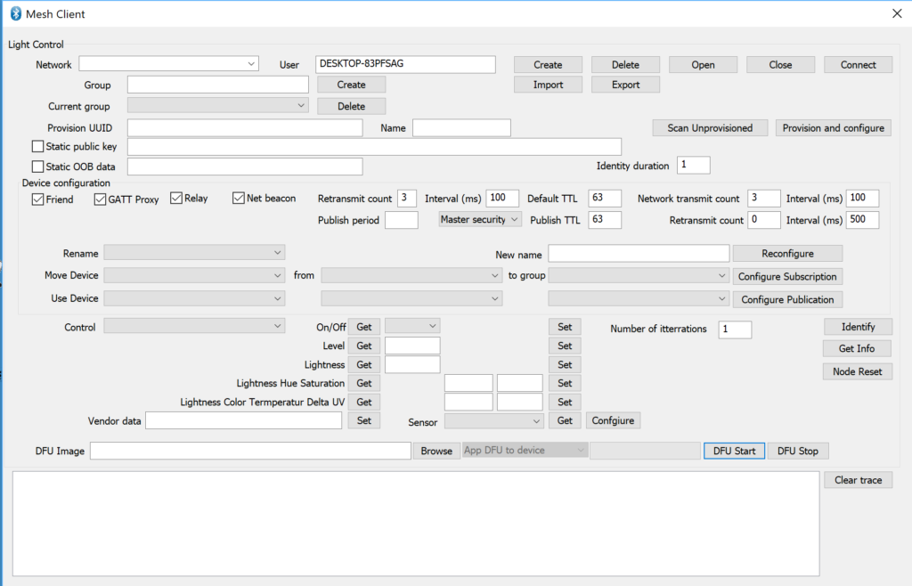
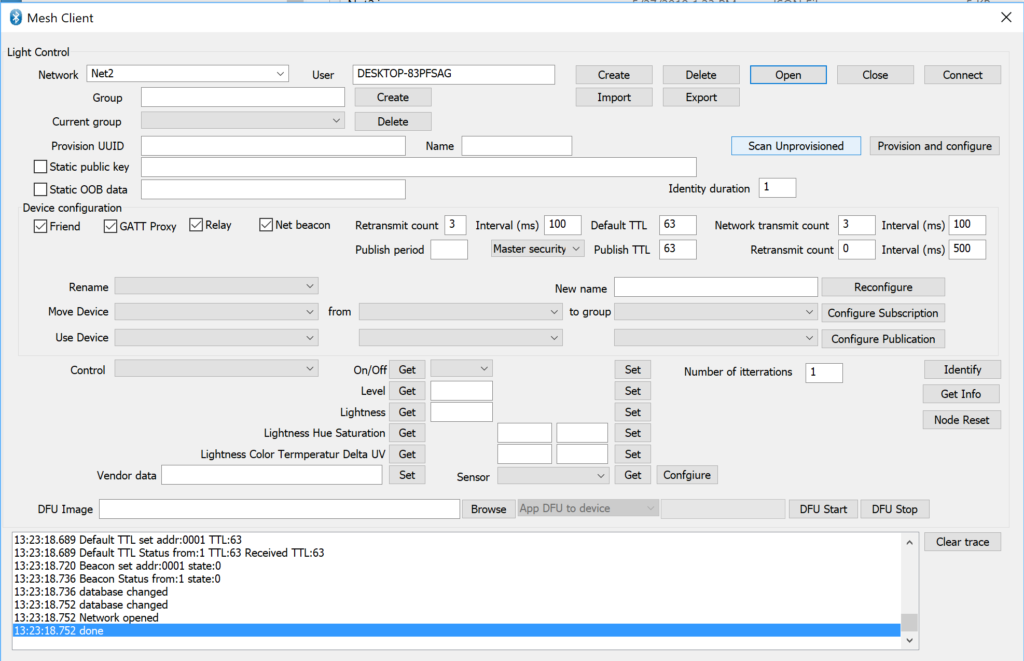
    When you run the Mesh Client it will look like this:

    Create a New Network

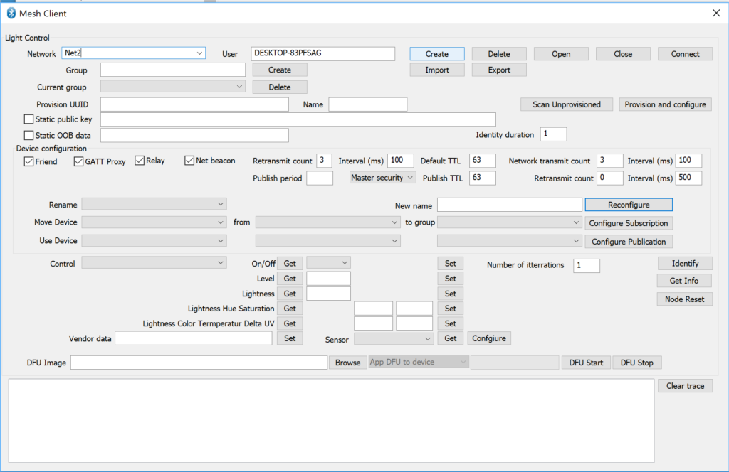
    Before it will do anything, you need to create a new network by giving it a name such as “Net2” and pressing “Create”.  This will populate all of the configuration files required to control the network.

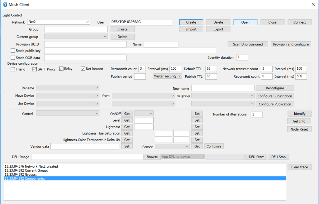
    After the network is created, press the “Open” button.

    After the network configuration files load you will see a trace window like this:

    Provision your L1 Dimmable Light to the Network

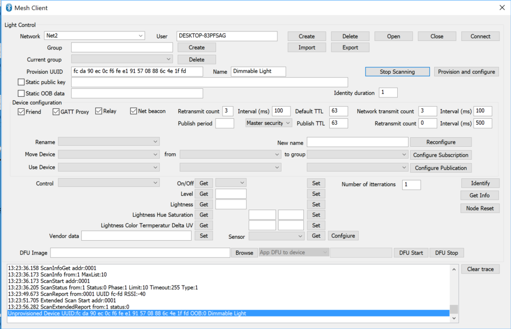
    Now you have a network with no nodes.  Press “Scan Unprovisioned” to find an unprovisioned device, which are just BLE devices that are advertising as mesh beacons.

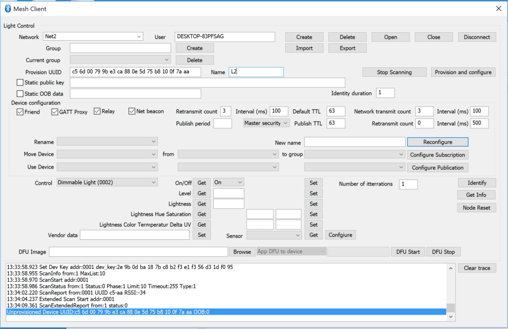
    After a bit, the scanner will find your “Dimmable Light”. You will see the device show up in “Provision UUID” with a name.   You can click Stop Scanning so that it doesn’t keep searching for other devices. Right here, I would recommend you change the device name.  Unfortunately I forgot when I captured these screens.  Oh well.  I hope when I do this live I won’t forget.  Now press “Provision and configure”.  After a some time that process will complete.

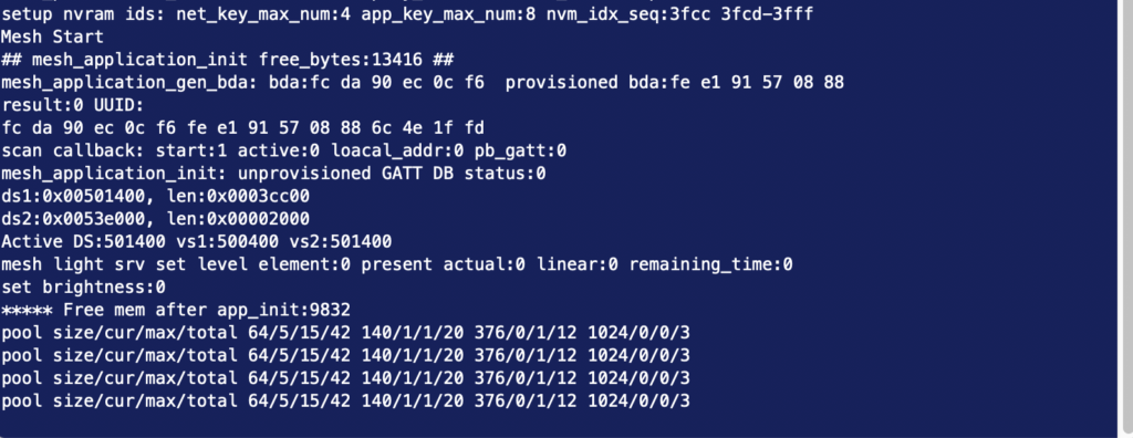
    While the provision and configuration process is going on you will see the console of the Dimmable light reacting.

    Control the L1 Dimmable Light

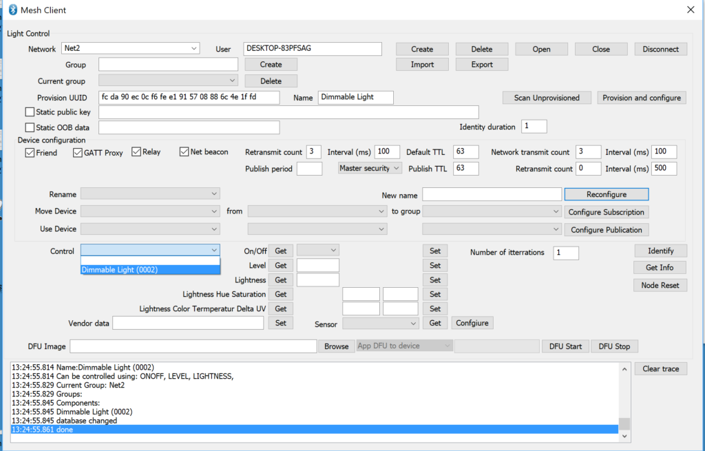
    Now that you have a provisioned node you can use the Mesh Client to control it.  Start by selecting which Node to control in the drop down dialog box.  In this case I chose “Dimmable light” which makes sense as it is the only device in my network.

    Now select “On” and “Set” which will turn on the LED.

    Add the other Dimmable Light to the Network & Test

    Unplug the Dimmable Light and plug it into something other than your computer.  Plug in the other unprovisioned board.  Back in the Mesh Client application press “Scan Unprovisioned”  When it comes back having found the new board,  give it a name “L2” and then press “Provision and configure”.  When I do this live during the workshop I will name the first board “L1” and the second “L2”.  But I’m not going to recapture these screen shots.

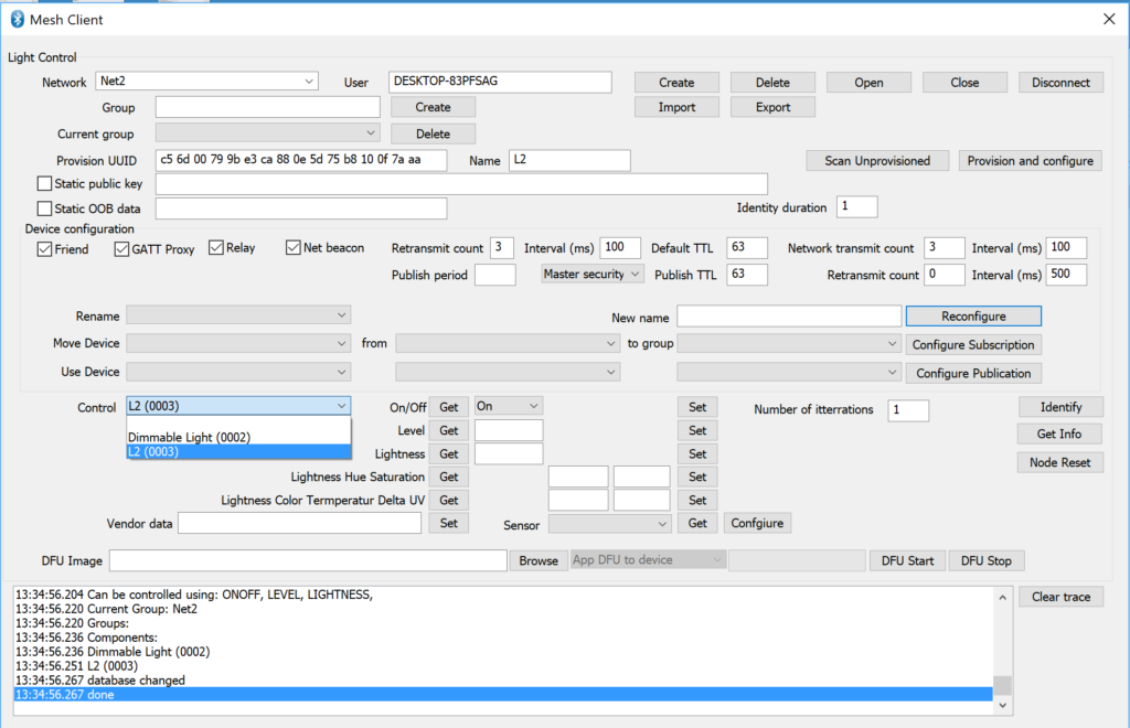
    Once L2 is provisioned into the network.  I can control it the same way I did with “L1”.  Select “L2” (and notice that I called the first light “Dimmable Light” rather than giving it a sensible name.

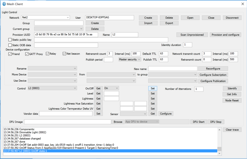
    Now select “On” and then press “Set”

    Finally, test and make sure that the first Dimmable Light is still working by turning it off:

    Mouser Bluetooth Mesh: L2A Using the CYBT-213043-MESH & Building a Mesh Network Using the Mesh Lighting App

    How To Design With Bluetooth Mesh


    You can "git" a workspace will all of these files at https://github.com/iotexpert/MouserVTWBluetoothMesh or git@github.com:iotexpert/MouserVTWBluetoothMesh.git

    Summary

    In this lesson I will walk you through the process of creating your first Bluetooth Mesh Network.  It will be a simple network with two Dimmable Light nodes which we will control using an Android Application called Mesh Lighting.

    In this exercise I will:

    1. Show you the CYBT-213043-MESH development kit
    2. Create a Dimmable Light Bulb Project and Program (two boards)
    3. Create a Mesh Network using MeshLighting Android Application
    4. Add another Dimmable Light to the Mesh
    5. Create Groups (a.k.a. Rooms)

    CYBT-213043-MESH

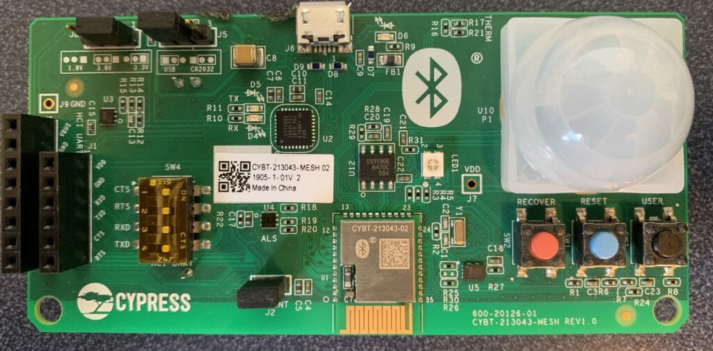
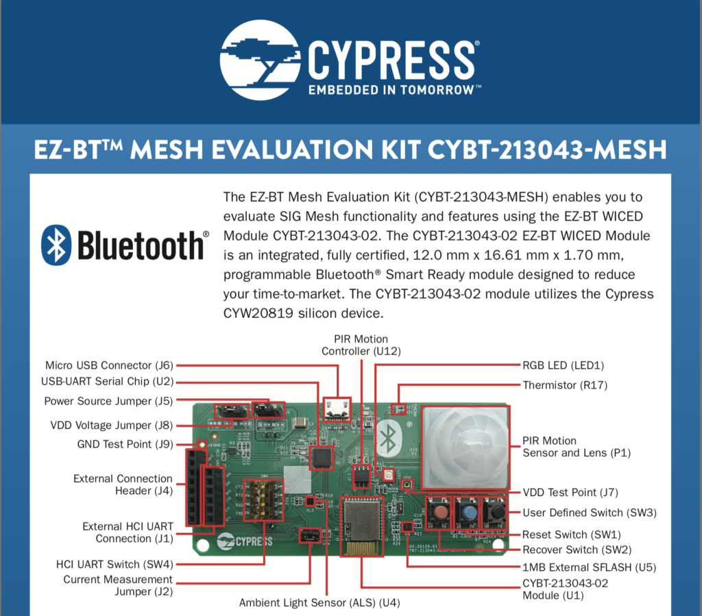
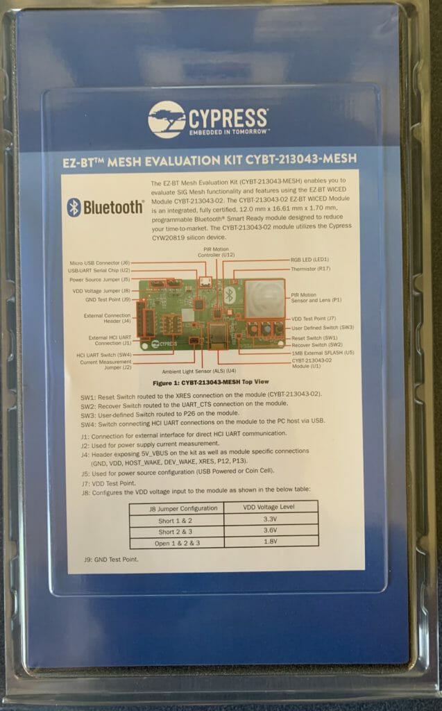
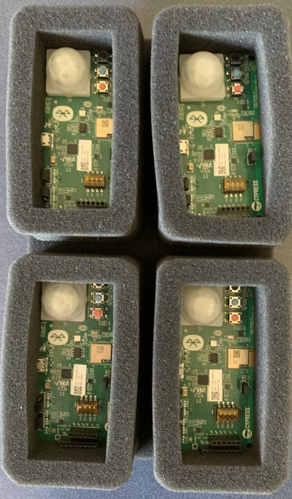
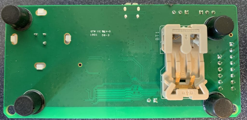
    Here is a picture of one of the development boards.  It has

    • A CYBT-213043-02 module with a PCB antenna.  The module contains a CYW20819
    • A two channel UART to USB device used for programming and debug printing
    • Three buttons (Reset, Recover and User)
    • An Ambient Light Sensor
    • An RGB LED
    • A thermistor
    • A PIR motion sensor

    Create a Dimmable Light Bulb Project and Program (two boards)

    Start this process by programming two of the boards with the Dimmable Light firmware.  To create this firmware start with File–>New–>Modustoolbox IDE Application

    Choose the CY214043-MESH development kit

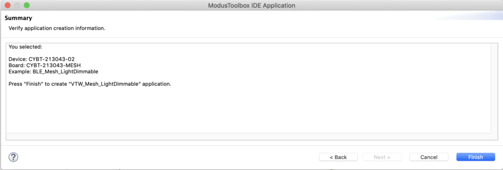
    Then pick “BLE_Mesh_LightDimmable” and give it a name “VTW_Mesh_LightDimmable”

    Now press finish to make the project.

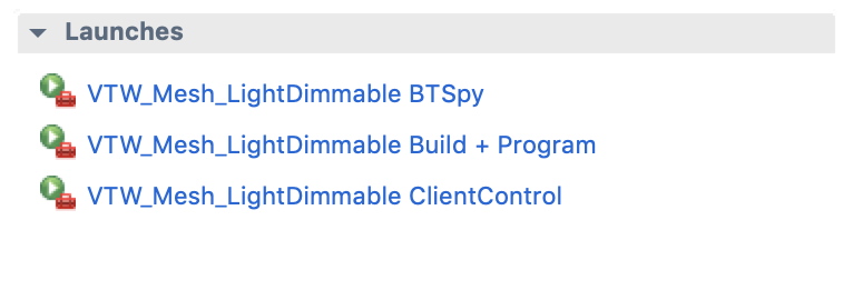
    Modus Toolbox provides a Launches window on a “quick panel” right below the workspace explorer.  Pick “VTW_Mesh_LightDimmable Build + Program”

    The compiler will run and make an executable.  Then it will program the flash of the CYW20819.

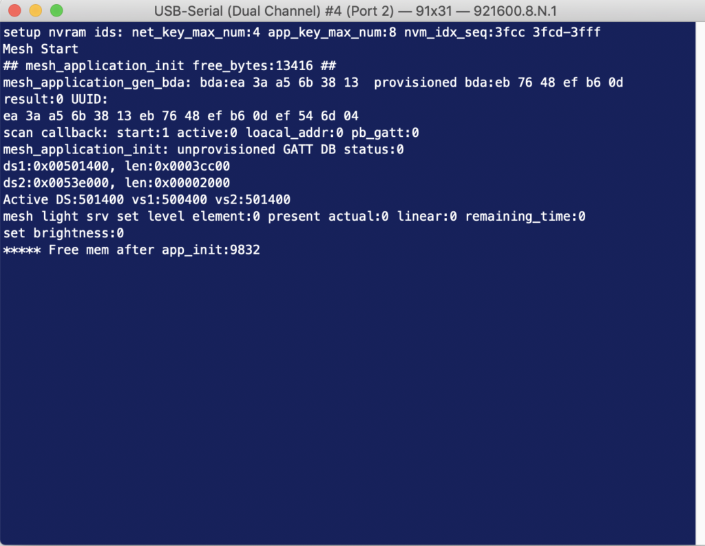
    On a Serial Console you should see the Application Bootup (notice that the baud rate is 921600). Remember there are 2 UART channels on each kit – one primarily used for programming and one used for debug messages. Make sure to connect to the second channel called the peripheral UART or PUART.

    Create a Mesh Network using MeshLight Android Application

    We provide the Android Application called “WICED Mesh Lighting App” and all of the source code as part of the SDK distribution in Modus Toolbox.  You can find it here:

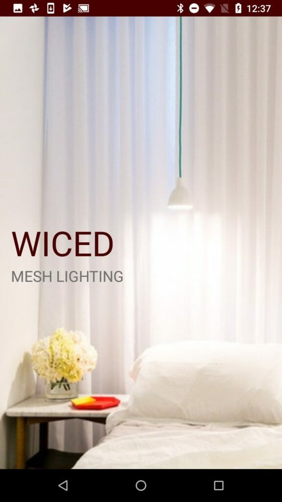
    Start the process on your Android phone by running the “WICED Mesh Lighting App”

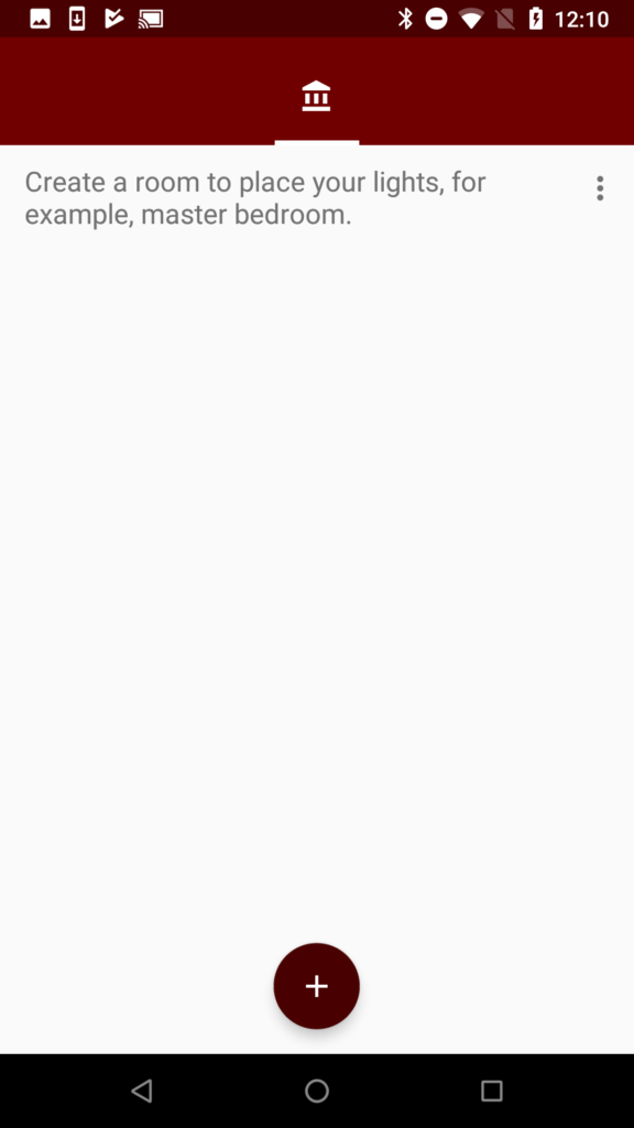
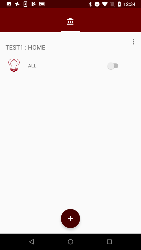
    Once the App starts, your screen should look like this:

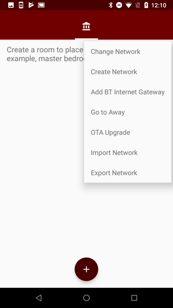
    Press the three dots icon and select “Create Network”

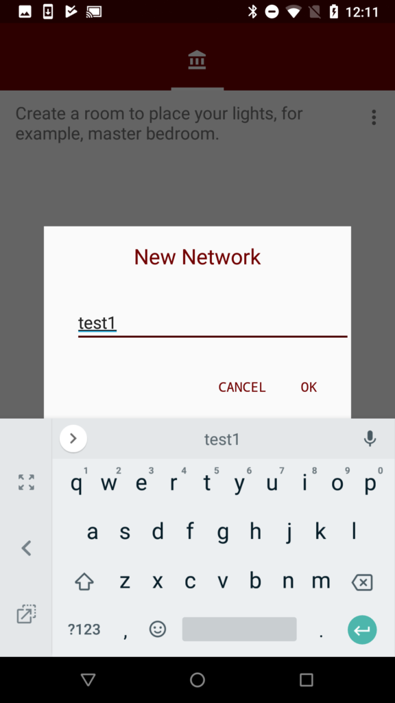
    Give it a name.  In this case I chose “test1”

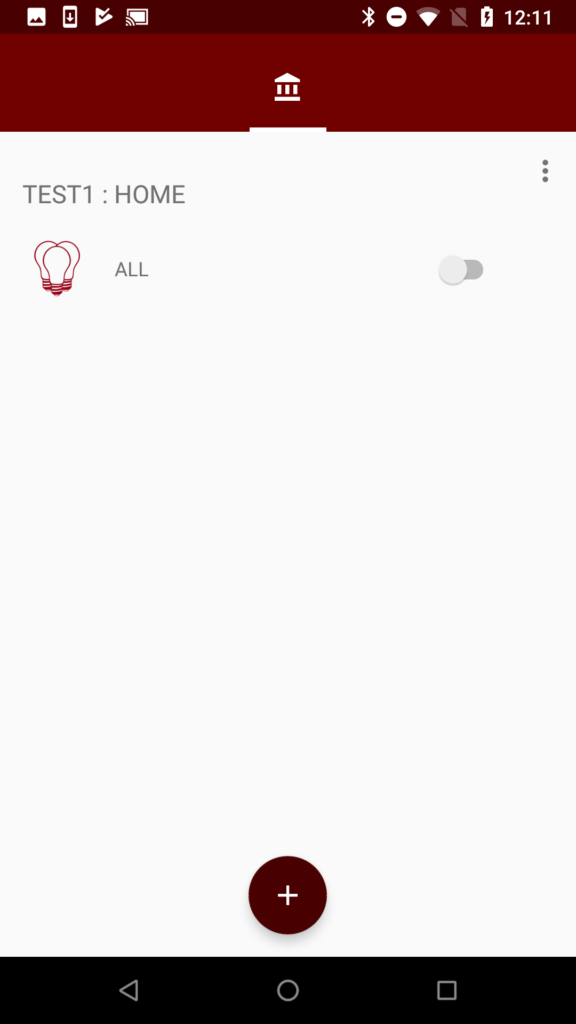
    Click on “ALL”

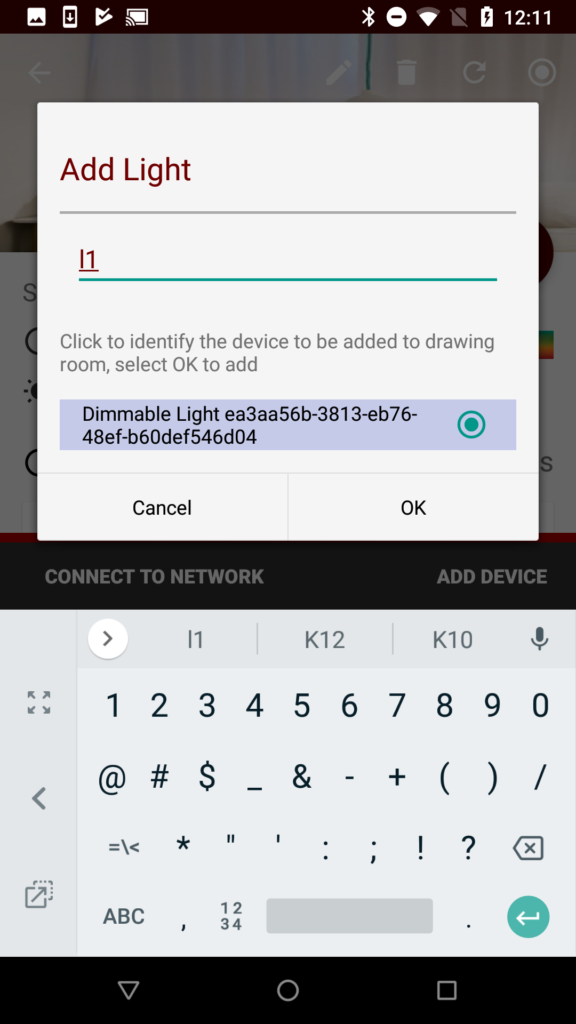
    Then press “Add Device”.  Your screen will search for an Unprovisioned Mesh Device.  When it finds one it will bring up the Name of the device along with the UUID.  I give the device the name “l1” and I attach that name to the “Dimmable Light….”.  After you get that done press OK.

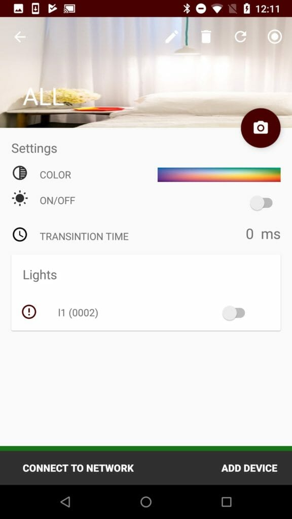
    After you press OK the App will provision and configure your Dimmable Light.  After that is done, your screen will look like this.

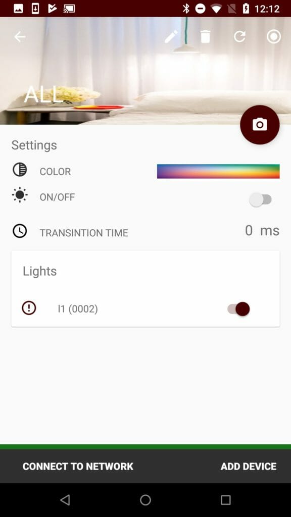
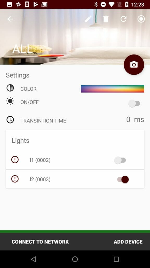
    The green bar along the bottom of the screen indicates that your phone is connected to the network – if it is red, you can click on “Connect to Network”. You can now control the LED using the little switch icon on the right.  In this picture I have the L1 turned on.

    Add another Dimmable Light to the Mesh

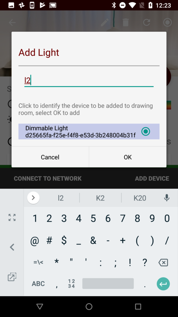
    One Dimmable Light, this is not much of a mesh.  To fix that I program another development kit.  Then I click on all and “Add Device”  After a bit you can add the next kit to your network.  Notice I call this one “l2”

    After the provisioning and configuring your screen will look like this.  Once again you can turn the lights on individually or as a group.

    Create Groups (A.K.A. Rooms)

    It is common for the home automation system to have “Rooms”.  In the world of Bluetooth Mesh these are called “Groups”  To create a group start on the main screen and click the “+” to create a new room

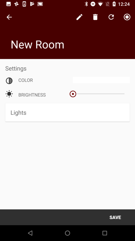
    On the New Room screen click the pencil icon.

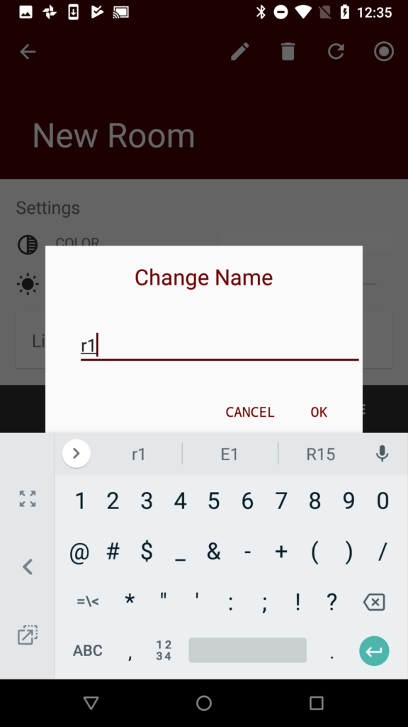
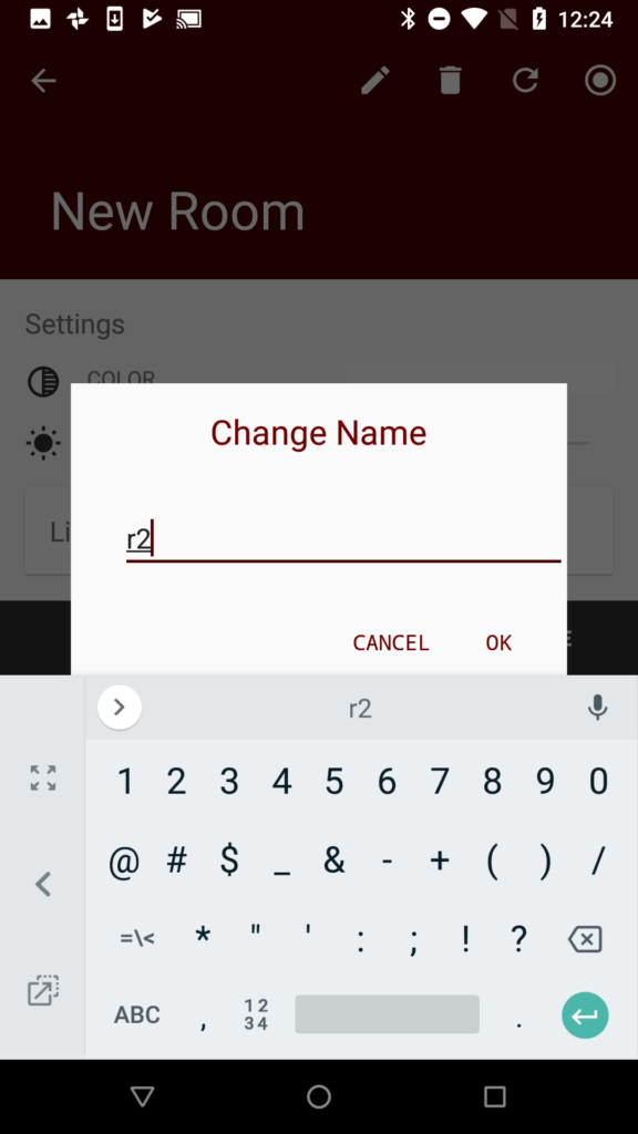
    Then type the name of the room.  In this case “r1”

    Now do the same thing to make “r2”

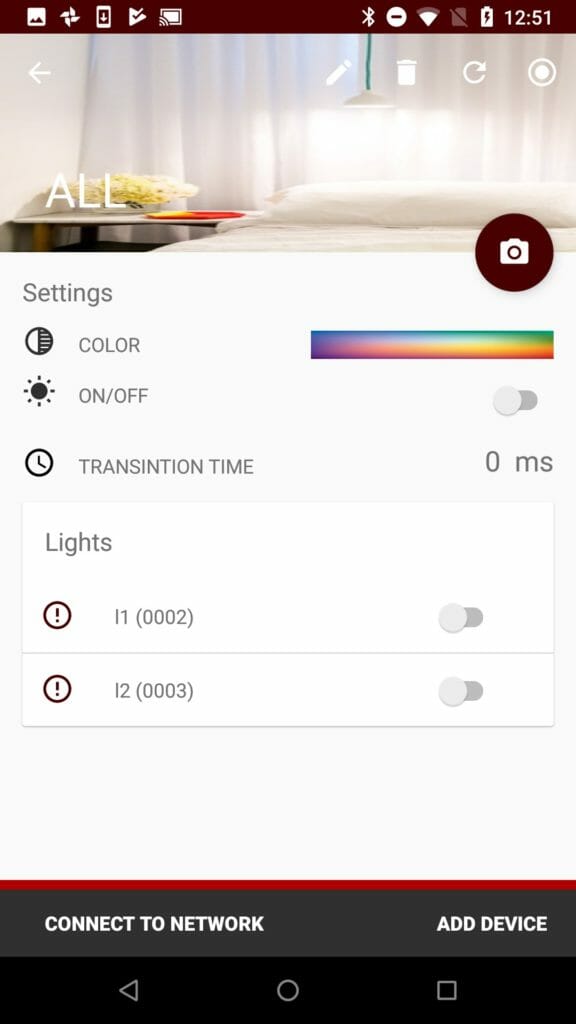
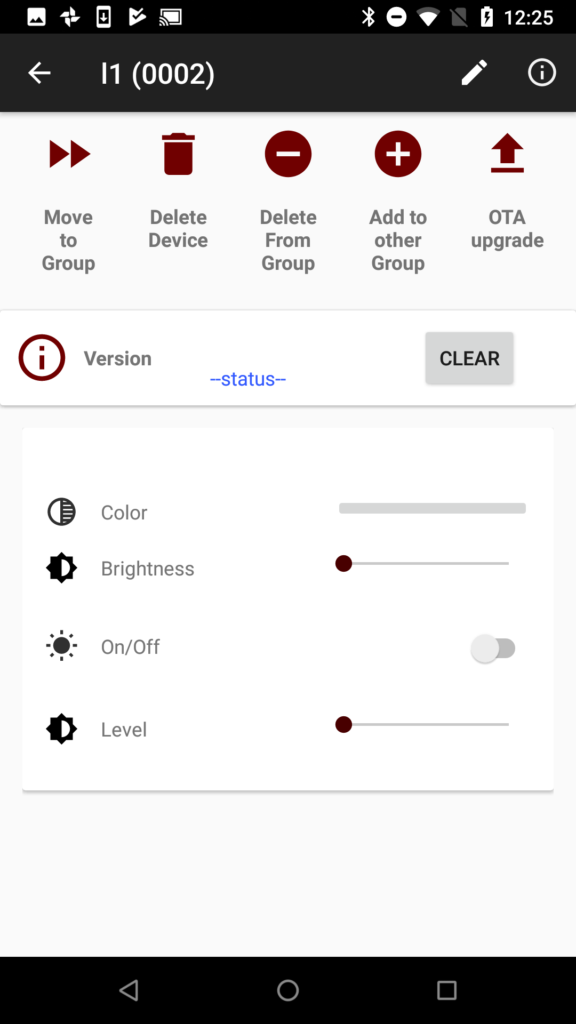
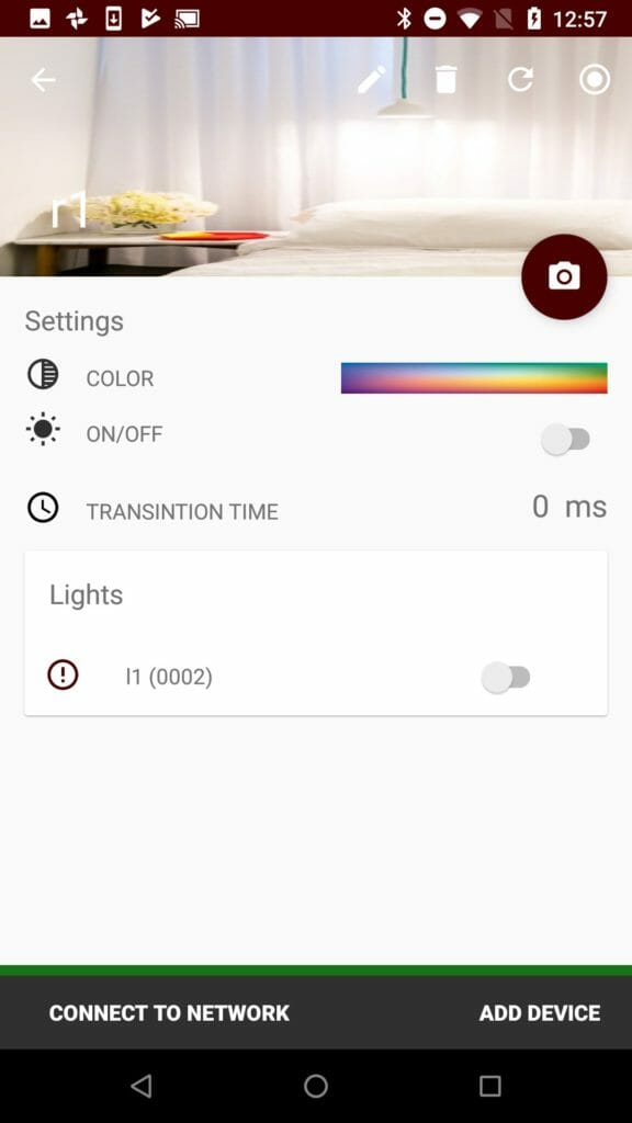
    Back in the “All Screen” you can click on the individual Dimmable Lights to move them around.  Start by moving l1 by clicking on it.

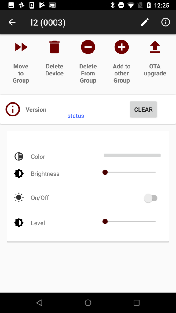
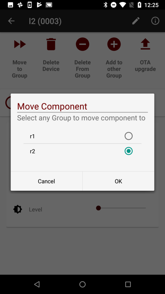
    Click on the “Move to Group” button.

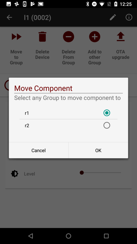
    And assign l1 to r1

    Go back.  Then click on l2.

    And move it to “r2”

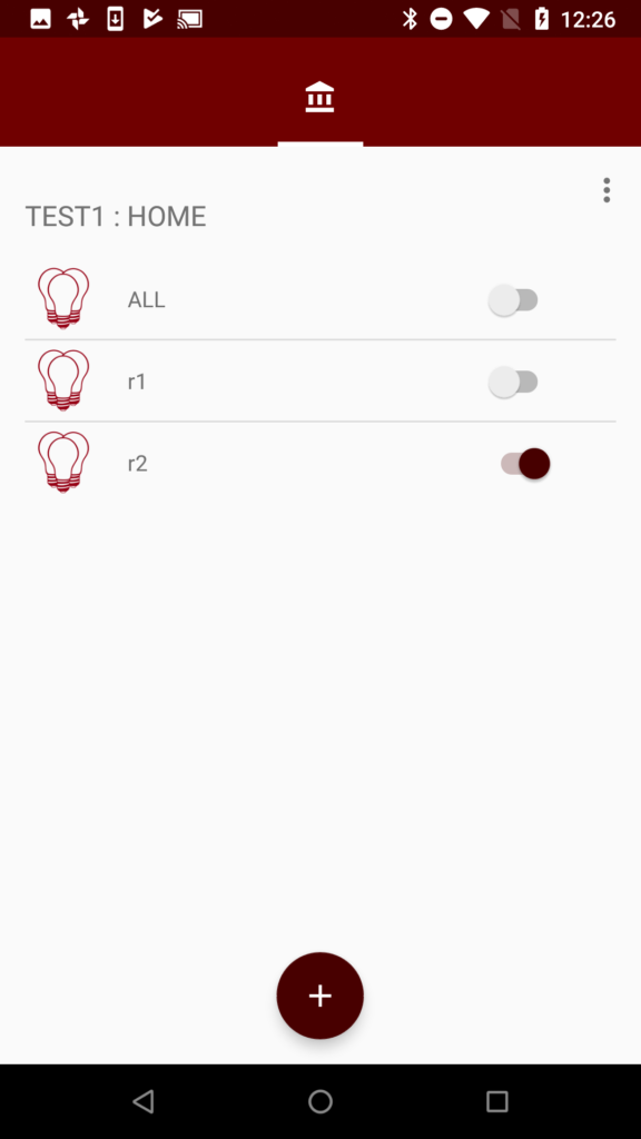
    Now you have this.  Three groups.  ALL, r1, and r2.  You can turn everything in those groups on by pressing the switch.  In the screen capture below I turned on “r2”

    One more interesting thing to do is to add l1 and l2 to the All group.

    Start on the main screen and click “r1”.

    Then click “l1”.

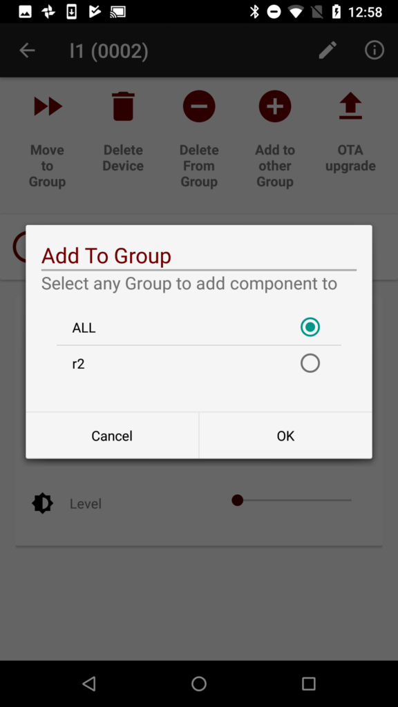
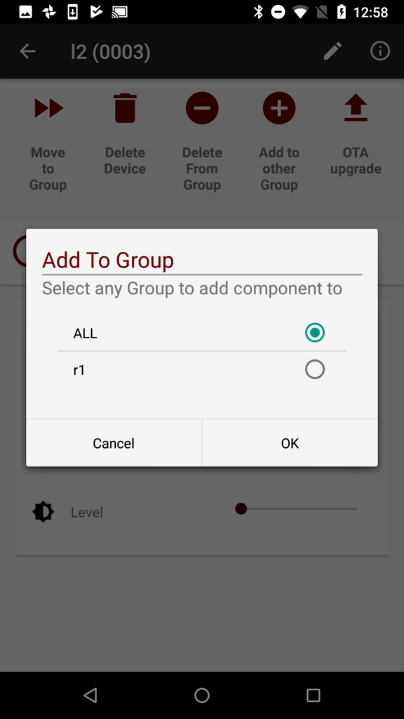
    Press “Add to other Group” and select “ALL”

    Go back and press on “r2”, select “l2” and then press “l2” and “Add to other Group”.

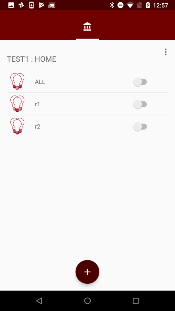
    Now you can control the “All” group, “r1” or “r2”.


    Mouser Bluetooth Mesh: L1 Developer Resources

    How To Design With Bluetooth Mesh


    You can "git" a workspace will all of these files at https://github.com/iotexpert/MouserVTWBluetoothMesh or git@github.com:iotexpert/MouserVTWBluetoothMesh.git

    Summary

    This lesson has a bunch of links to useful documentation about Bluetooth Mesh.  It includes links to all of the Cypress software and application notes.  It also includes links to the Bluetooth Special Interest Group website for the BLE Mesh Specs.

    Cypress Resources

    1. Cypress Bluetooth Mesh Landing Page
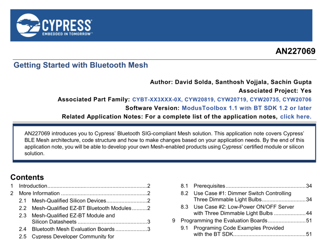
    2. AN227069 – Getting Started with Bluetooth Mesh
    3. EZ-BT Mesh Evaluation Kit Landing Page
    4. EZ-BT Mesh Evaluation Kit QuickStart
    5. Modus Toolbox
    6. Cypress Bluetooth Community
    7. Bluetooth SDK 1.2
    8. Modus Toolbox Bluetooth SDK Examples @ github
    9. Cypress WICED Bluetooth 101 – Class
    10. Mesh Client
    11. Mesh Client Documentation

    Bluetooth Sig Resources

    1. Bluetooth SIG Mesh Specs
    2. Bluetooth SIG Mesh Profile Spec
    3. Bluetooth SIG Mesh Model Spec
    4. Bluetooth SIG Mesh Device Properties
    5. Introducing Bluetooth Mesh Networking
    6. Intro Bluetooth Mesh Part 1
    7. Intro Bluetooth Mesh Part 2
    8. Bluetooth Mesh Fundamental Concepts of BT Mesh Networking Part1
    9. Bluetooth Mesh Fundamental Concepts of BT Mesh Networking Part2
    10. Bluetooth Mesh Networking: Friendship
    11. Management of Devices in a Bluetooth Mesh Network
    12. In-Market Bluetooth Low Energy Devices and Bluetooth Mesh Networking
    13. Bluetooth Mesh Security Overview
    14. Provisioning a Bluetooth Mesh Network Part 1
    15. Provisioning a Bluetooth Mesh Network Part 2

    Other Useful Links

    1. Wikipedia Bluetooth Mesh

    Cypress Bluetooth Mesh Landing Page

    AN227069 – Getting Started with Bluetooth Mesh

    EZ-BT Mesh Evaluation Kit Landing Page

    EZ-BT Mesh Evaluation Kit QuickStart

    Modus Toolbox

    Cypress Bluetooth Community

    Bluetooth SDK 1.2

    Modus Toolbox Bluetooth SDK Examples @ github

    Cypress WICED Bluetooth 101 – Class

    Mesh Client

    Mesh Client Documentation

    Bluetooth SIG Mesh Specs

    Bluetooth SIG Mesh Profile Spec

    Bluetooth SIG Mesh Model Spec

    Bluetooth SIG Mesh Device Properties

    Introducing Bluetooth Mesh Networking

    Intro Bluetooth Mesh Part 1

    Intro Bluetooth Mesh Part 2

    Bluetooth Mesh Fundamental Concepts of BT Mesh Networking Part1

    Bluetooth Mesh Fundamental Concepts of BT Mesh Networking Part2

    Bluetooth Mesh Networking: Friendship

    Management of Devices in a Bluetooth Mesh Network

    In-Market Bluetooth Low Energy Devices and Bluetooth Mesh Networking

    Bluetooth Mesh Security Overview

    Provisioning a Bluetooth Mesh Network Part 1

    Provisioning a Bluetooth Mesh Network Part 2

    Mouser Bluetooth Mesh: L0 Introduction

    Summary

    Register for my Bluetooth Mesh Virtual Workshop on May, 29 at 11:00AM Eastern Time!!

    Block Diagram - Cypress Semiconductor CYBT-213043-MESH Bluetooth Evaluation Kit

    Hello everyone.  This is lesson 0 of a series of 10 lessons about creating Bluetooth Mesh applications for the Cypress EZ Bluetooth Mesh Evaluation Kit CYBT-213043-MESH.  This class is called “How to Design with Bluetooth Mesh” because that is exactly what we are going to do – make some applications.  No powerpoint in sight.

    I am going to start by showing you the development kit and demonstrating how to use it.  It is actually 4 development kits, which makes sense because you need multiple boards to make an actual Bluetooth Mesh.  I will show you and Android App called the “Mesh Lighting” app which I will use to provision, configure and control the mesh.  My plan is to walk you through a bunch of learning resources about Bluetooth Mesh and teach you the key concepts.  Finally, I’ll show you some code and teach you how to write your own projects.

    I will attempt to go slowly enough for you to follow along, but if I go too fast, don’t worry you should be able to follow along with the instructions on this website.

    Todays virtual workshop has this agenda table which will show also show up on every page.  The links will work to take you through the different lessons.

    How To Design With Bluetooth Mesh


    You can "git" a workspace will all of these files at https://github.com/iotexpert/MouserVTWBluetoothMesh or git@github.com:iotexpert/MouserVTWBluetoothMesh.git

    You will need a few things for this class:

    CYBT-213043-MESH

    This “development kit” is actually four identical boards (and cables) which will let you build a complete Bluetooth Mesh.  You can purchase the kit from Mouser.

    Modus Toolbox 1.1

    Modus Toolbox 1.1 is our Eclipse based IDE for developing Bluetooth projects.  You can run this on Windows, Mac and Linux.

    Bluetooth Mesh SDK 1.2

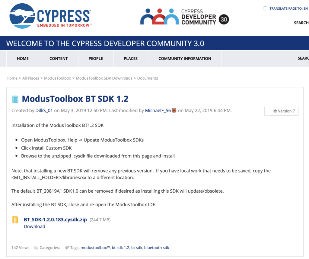
    Cypress has been working continuously to keep our Bluetooth Mesh SDK up to date with changes in the Bluetooth SIG specifications for Mesh.  Our latest release as of today is Bluetooth SDK 1.2 which you will need to have installed.

    IoT Expert Logo -> EPD – Bitmap Madness (Part 2)

    Summary

    In the last article I showed you how to display a bitmap in the Segger format.  In this article I will show you how to convert a BMP to a “C” file and then display it using the Segger GUI_BMP_Draw() API.

    To this I will follow these steps:

    • Use GIMP to Export a Black and White Logo
    • Convert the BMP to a “C” array using Bin2C
    • Add the C to the project and fix up the project

    Use GIMP to Export a Black and White Logo as BMP

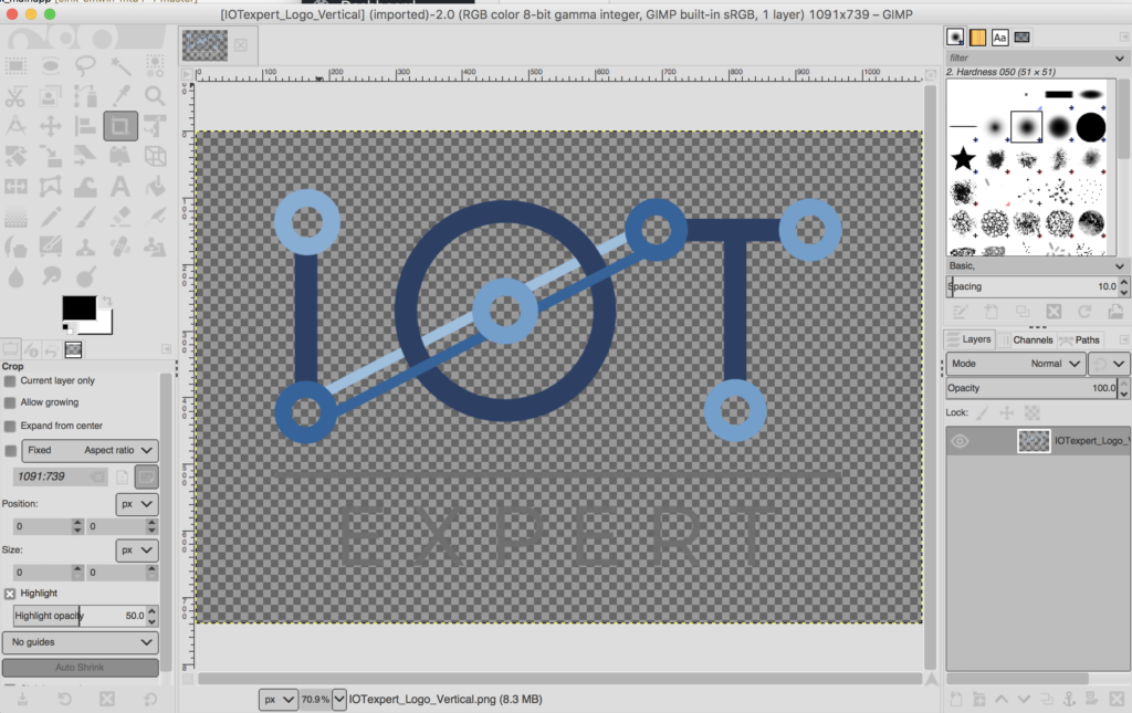
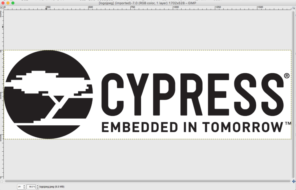
    As in the last article, Ill use GIMP to manipulate the IoT Expert.  First, Ill load the logo from the PNG file.

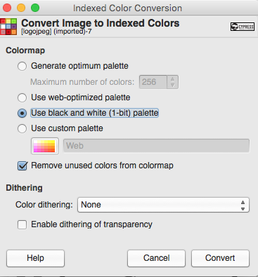
    Then I will convert the PNG to a black and white only image.  This will be a 1-bit per pixel indexed image.  Indexed means that instead of ARGB (aka 32 bits for each pixel), that the color of each pixel will be referenced via an index into a color table.  For instance the color table might look like this:

    Index Value Color
    0 0xFF000000 Black
    1 0xFFFFFFFF White

    The BMP file will then have a color table (like the one above) and each pixel value will be an index into the table.  It turns out that these color tables must have  2^n rows where n is the number of bits in the index.  Also with the BMP format any bitmaps with 24 bits per pixel will not have a color table.

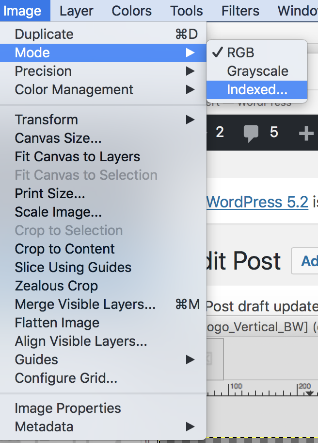
    Gimp can convert an image to indexed.  To do this, click  Image–>Mode–>Indexed…

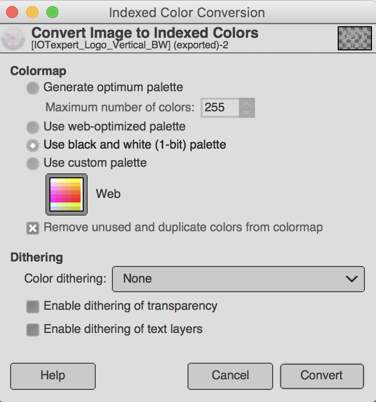
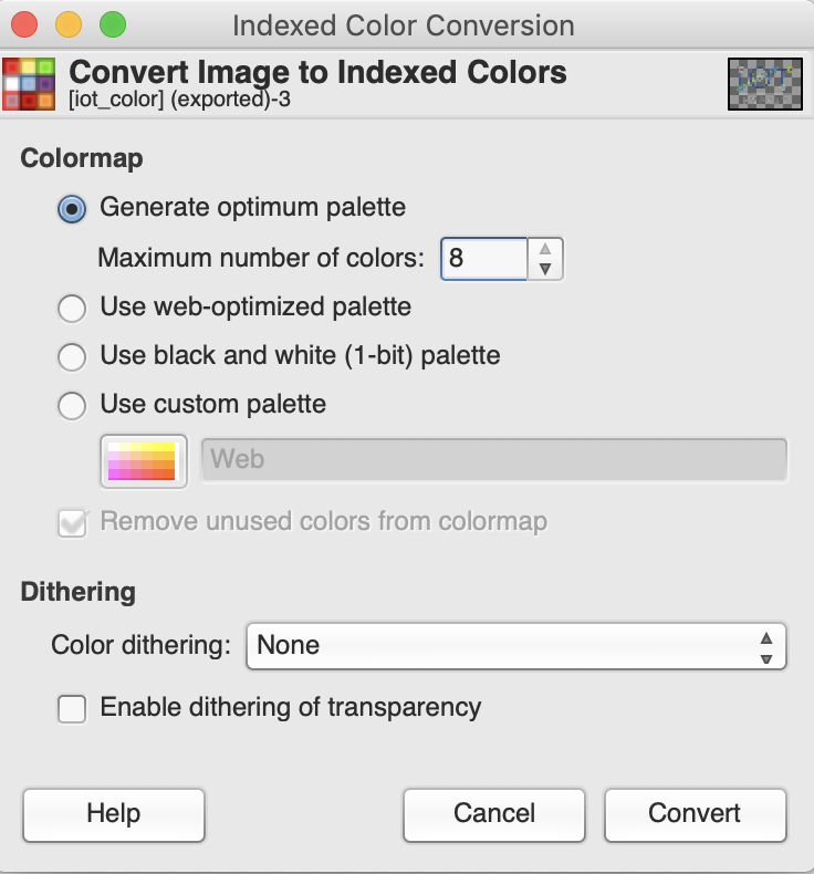
    On this screen you will be given the option to specify the color indexes.  Notice that there is a “black and white only” option.

    Once you have made the conversion you can see that image is now indexed.

    On that screen you could have converted the image to indexed with up to 256 colors (but I choose 2 by using the Use black and white (1-bit) palette.

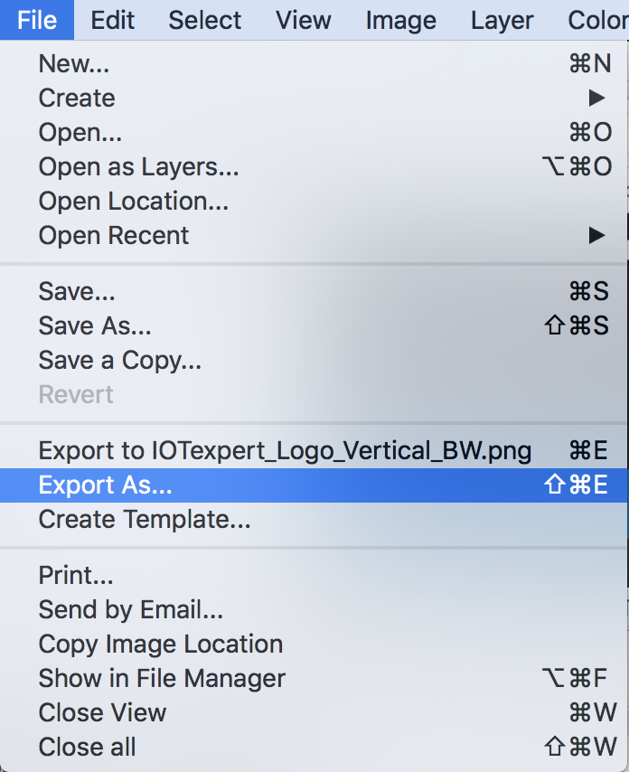
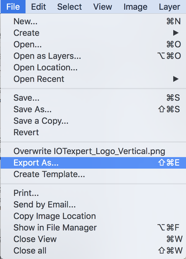
    The next step is to export to a BMP using “File–>Export As…”

    I set the file name to “IOTexpert_Logo_Vertical_BW.bmp”.  Gimp does its magic by using the file extension.  In this case “bmp” creates a Microsoft BMP file.

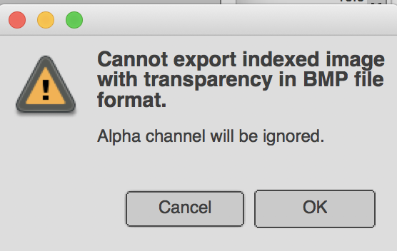
    When I hit export I get this dialog box (which I had no idea what it meant when I started). For now click “OK”

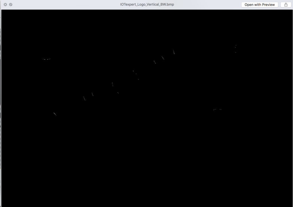
    Once the file is exported this is what I get.  OK… is not very helpful.  What happened?

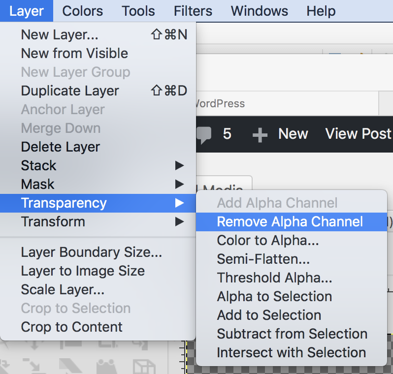
    The answer is that an Indexed BMP does not support Alpha.  So, GIMP ditched the Alpha, which turned everything that wasnt black to the background color, which is black. So, what is the deal with the Alpha channel?  Alpha is how transparent everything is.  You can get rid of it using Layer–>Transparency–>Remove Alpha Channel

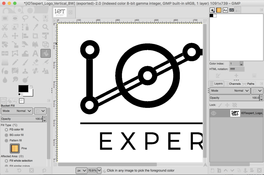
    Which once again turns my image black.  But why?  On the left hand side of the screen you will see the foreground/background colors.  And you will notice that the background is black.

    To fix the problem undo the remove alpha.  Then click the little back and forth arrow to turn the background white.  Then re-remove the alpha.  Now that problem is fixed.

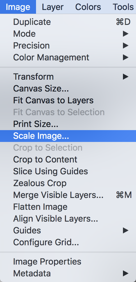
    Now, I can shrink it to the right size using Image–>Scale Image…

    Then pick the 276 width (aka the same width as the EPD screen)

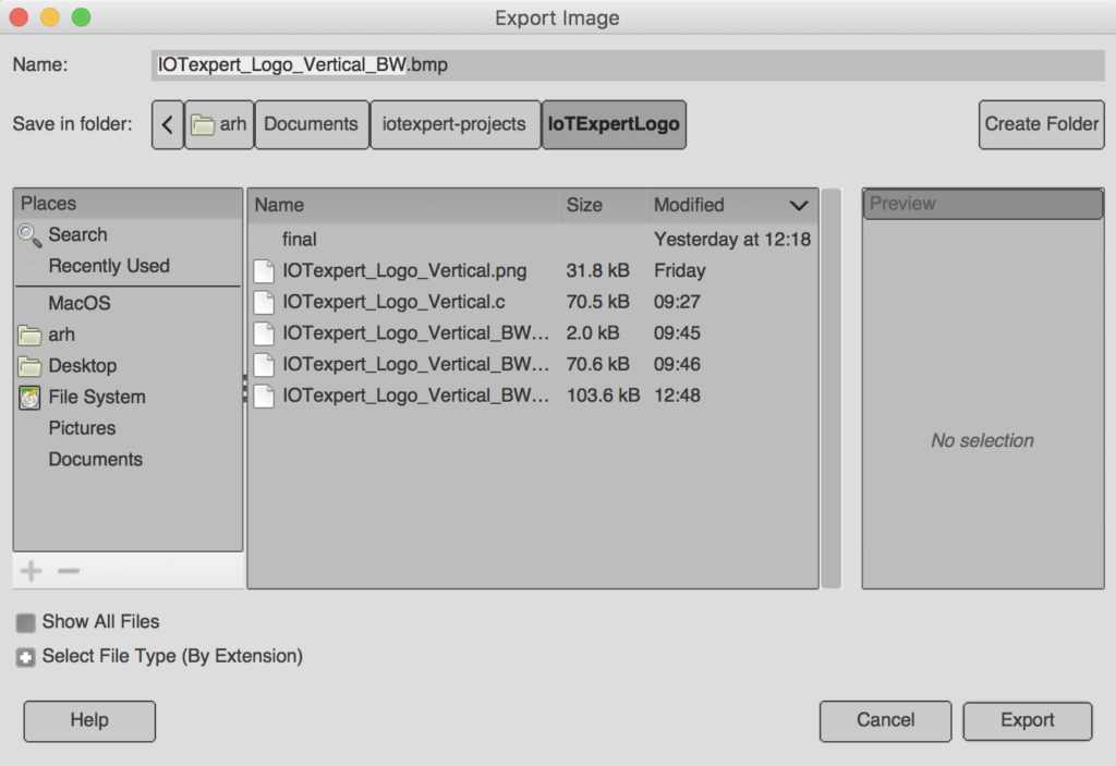
    Now do “File–>Export As..” with a “.bmp” file name extension.  This time it doesn’t ask me about the transparency.

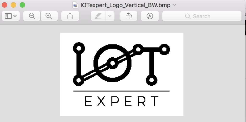
    And, now I have a nice BMP file.  Here is the view from the preview in Mac.

    So, how do I get a BMP file into my program?  Well, I need turn it into an array of bytes.  And to do that…

    Segger Bin2C

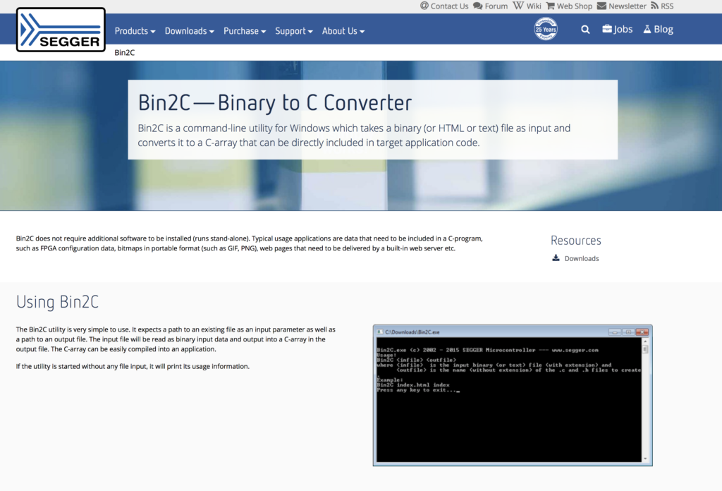
    One of the utility programs that Segger provides is called “Bin2C” which can read in a file and turn it into an array of bytes in “c” format.  You can download it here.

    When I run it, first I select the file, then press “Convert”

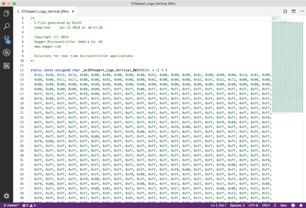
    And it generates a nice array of bytes.

    Update the Project

    To use the array, first copy the file into your project.  You notice that the array is defined as “static” which means that it is not accessible from other files.  Remove that.  Now edit the eInkTask.c and

    1. Add an extern reference to the array of bytes
    2. Make a call to “GMP_BMP_Draw()” to display the logo
    extern unsigned char _acIOTexpert_Logo_Vertical_BW[6862UL + 1];
    void ShowIoTScreen(void)
    {
    	GUI_Clear();
    	GUI_BMP_Draw(_acIOTexpert_Logo_Vertical_BW, 0,0);
    	/* Send the display buffer data to display*/
    	UpdateDisplay(CY_EINK_FULL_4STAGE, true);
    	while(1)
    		vTaskDelay(100);
    }

    When I program the kit I get this… all black.


    But why?  I didn’t know the answer.  So I assumed that it must be something to do with me and my understanding of bitmaps.  In the next article I’ll tell you all about that journey.  But after a day or two of learning about bitmap file formats I was convinced that it wasn’t me.  So I started looking around on the web and I found this thread on Segger’s forum.

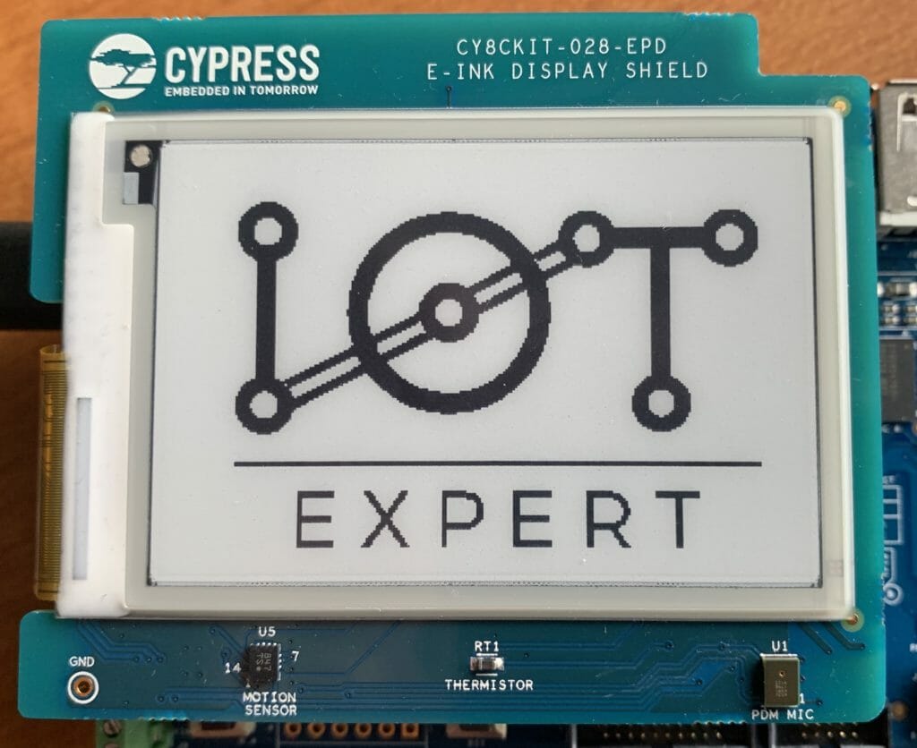
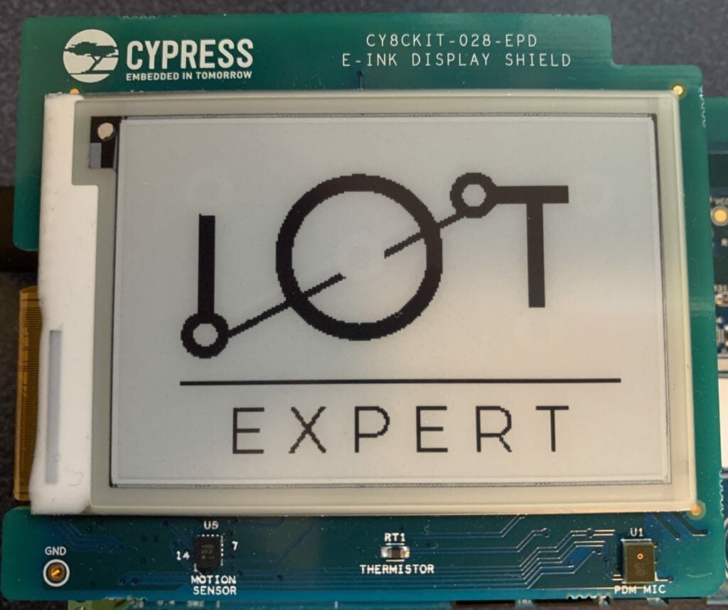
    And, when I got to work the next Monday I called an amazing engineer that works for Cypress in Ukraine. He provided me a v5.48 which sure enough fixed the problem.  When I program that, looks like things are working with bitmaps:

    Unfortunately that means that we (Cypress) have a released version of Segger emWin that is broken.  This will be fixed with an updated version soon, but for now if you are stuck send me an email and I’ll help you.

    The next article is a deep dive into the BMP format.

    IoT Expert Logo –> EPD – Bitmap Madness (Part 1)

    Summary

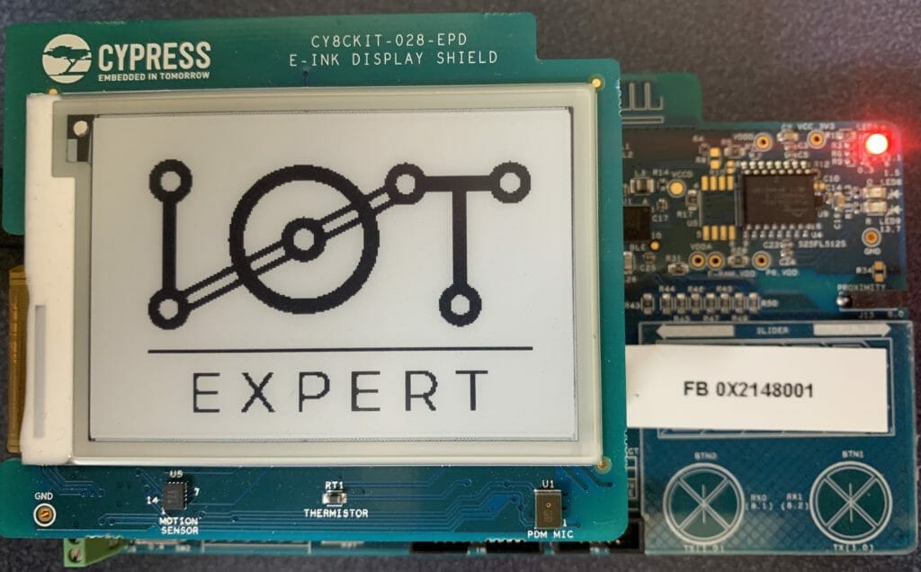
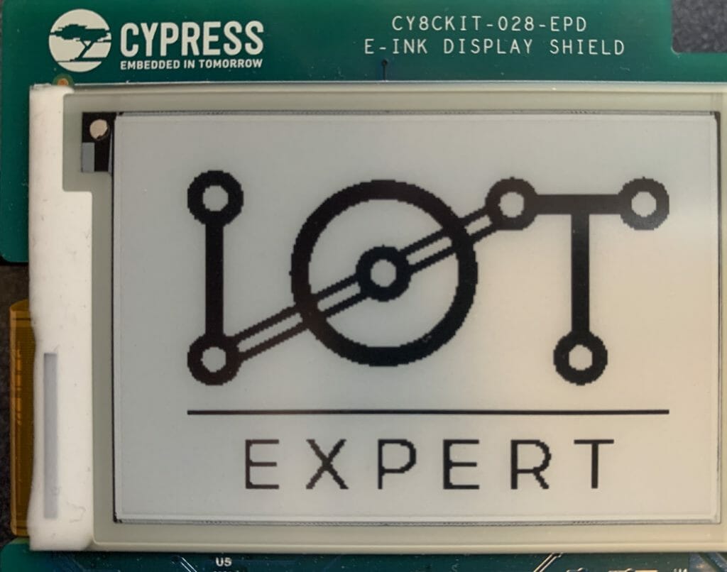
    In the last article I showed you a bunch of things about programming the Pervasive EPD eInk Display that is attached to the CY8CKIT-028-EPD.  You might have noticed in the first video I have a screen that shows the IoT Expert Logo.  Simple right?  Yes you would think, but it actually turned out to be quite a pain in the ass!  This article is my journey through bit maps.  It is hardly canonical, but hopefully it will help you.

    In this article I will specifically walk you through:

    • The IoT Expert Logo
    • Segger emWin Bitmap Drawing APIs
    • Segger Bitmap Converter
    • Updating a Project to draw a Segger Bitmaps
    • Converting a Color Bitmap to Black and White
    • Using GIMP to Fix B/W Conversion

    In the next two articles I will address drawing bitmaps that are in the Windows BMP format and PNG format.

    The IoT Expert Logo

    If you guys remember, in early 2017, I ran a design contest to create a logo for the IoT Expert website.  You can read about it here and here.  When it was over, I had a bunch of different images including this one which is a 1091×739 PNG file with what I thought was five colors but is actually nine (which I discovered during this journey)

    OK, thats cool.  But how do I get that onto the eInk screen which is 276×176 and black and white?

    emWin Bitmap Drawing APIs

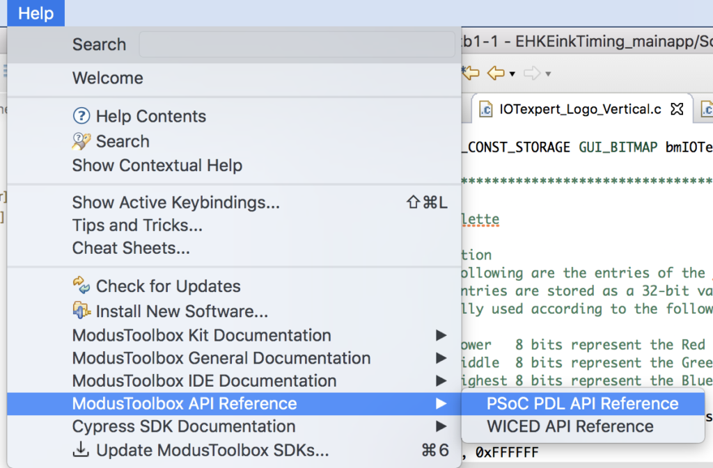
    I started by looking at the Segger emWin documentation which you can either get directly from the Segger website here.  Or you can find it inside of Modus Toolbox.  Select “Help–>ModusToolbox API Reference–>PSoC PDL Reference”

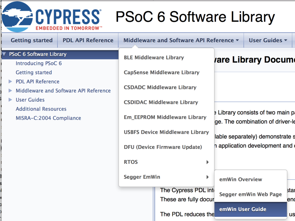
    Then pick “Middleware and Software API Reference –> Segger emWin –> emWin User Guide”

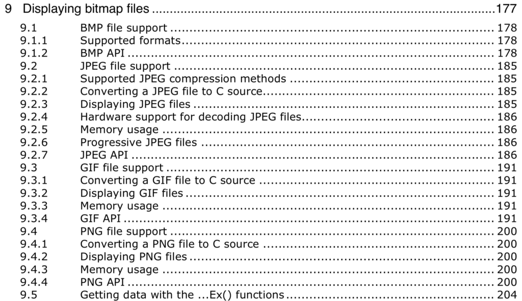
    From the documentation you see that emWin can display bitmaps in the emWin format using the APIs GUI_DrawBitmap.  This section actually goes on for more than another page worth of APIs.  The API that I will focus on in this article is GUI_DrawBitmap()

    You can also display bitmaps that are in GIF, PNG, BMP or JPEG format.

    Bitmap Converter for emWin

    I suppose the first question is, “How do I get a bitmap from my computer in PNG format into the Segger Bitmap format?”  Well, it turns out that Segger has a program called Bitmap Converter for emWin.

    This is a pay program, but you can download it to try it out.  It is sort of an old-school windows program.  So I installed it on parallels on my mac.  When you run it the first time it reminds me that this is not for production.  Got it!

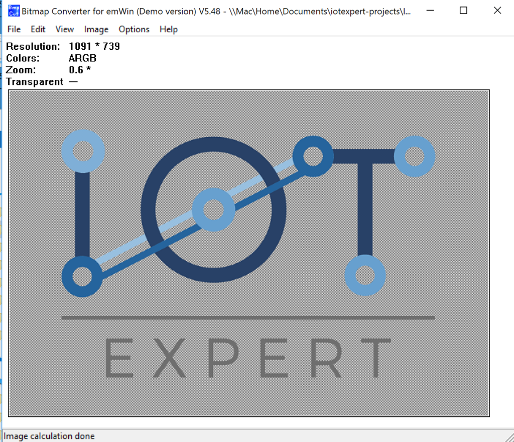
    I start by opening the PNG file of my logo.  Notice that it says the file is 1091 by 739 and in “ARGB” colors.  “ARGB” means Alpha, Red, Green and Blue. (more on this later).

    On the Image menu I start by picking “Scale..” to reduce the size.

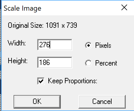
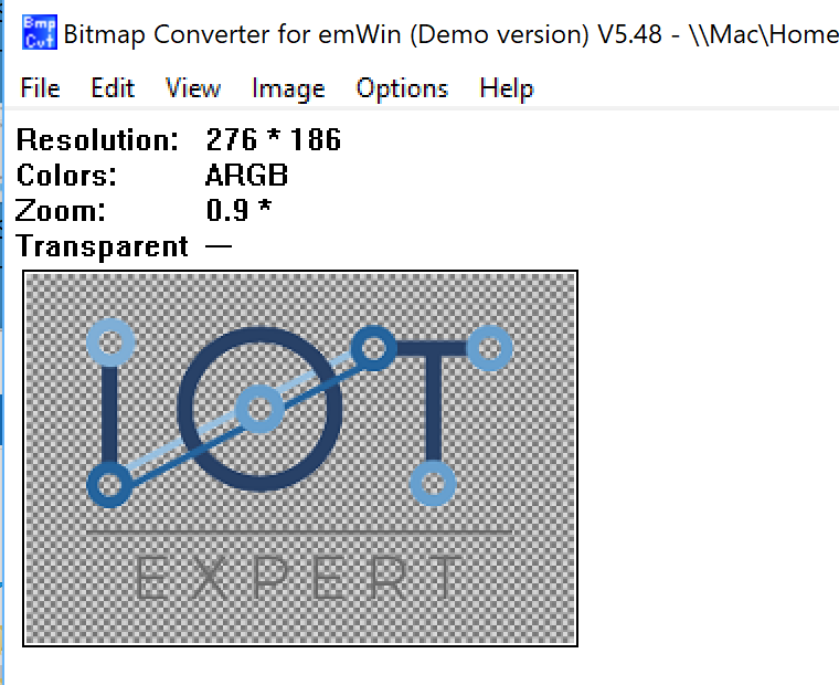
    I pick out 276 wide and it keeps the aspect ratio the same, which results in a height of 186 (actually 10 pixels to high)

    After clicking OK I get this.

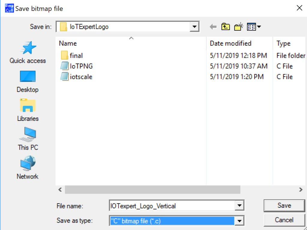
    Now, I want to take that bitmap and turn it into a “C” file that has the right data structures.  To do that pick “Save As..”

    Then pick “C” bitmap file (*.c)

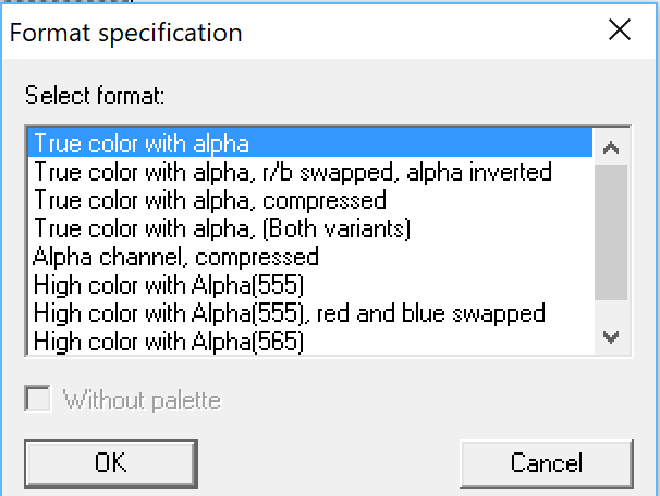
    Now, it asks me this question, which I didn’t really know the answer to. (more on this later) but I let the default be “True color with alpha”

    This created a “C” file called IOTexpert_Logo_Vertical.c” which seems to be OK.

    Updating a Project to draw a Segger Bitmap

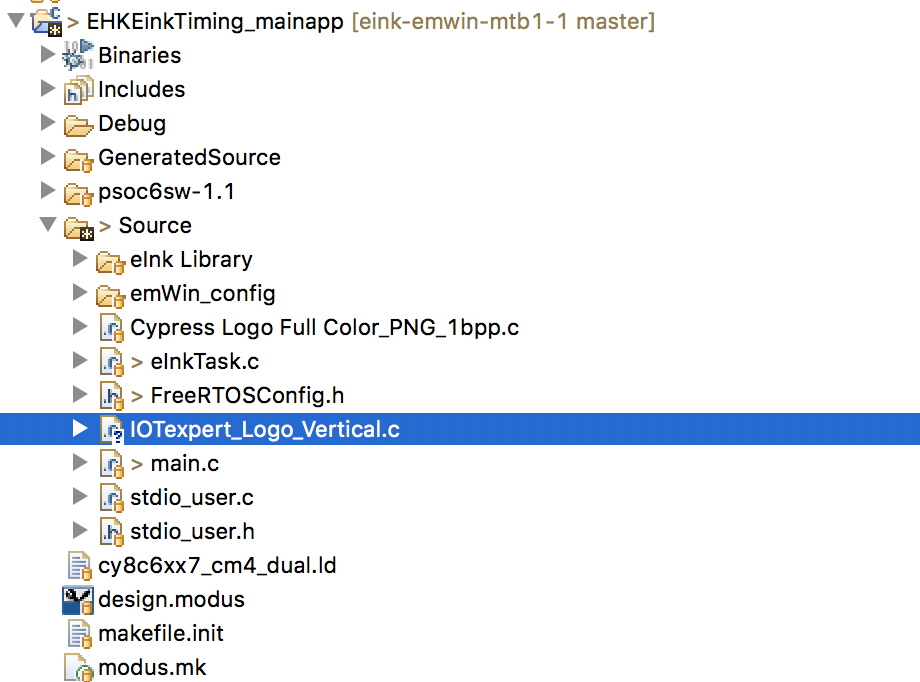
    Rather than make a new project.  I start with the project from the previous article.  I use the finder to copy/paste the c file into my project.  You can see it below.

    Then I double click on the file.  Here is the top.  Notice it reminds me that this is demo only.  And it gives me a little bit of information about the bitmap.  Specifically the width and height.  As well as the number of colors which is 32 bits per pixel.  It turns out that this is 4-bytes per pixel.  The first byte is Alpha and then one byte each for Red, Green and Blue.  Notice that it also declares an extern structure “extern GUI_CONST_STORAGE GUI_BITMAP bmIOTexpert_Logo_Vertical”.  This is exactly the right type to call the GUI_Drawbitmap function.

    /*********************************************************************
    *                SEGGER Microcontroller GmbH & Co. KG                *
    *        Solutions for real time microcontroller applications        *
    *                           www.segger.com                           *
    **********************************************************************
    *                                                                    *
    * C-file generated by                                                *
    *                                                                    *
    *        Bitmap Converter for emWin (Demo version) V5.48.            *
    *        Compiled Jun 12 2018, 15:10:41                              *
    *                                                                    *
    *        (c) 1998 - 2018 Segger Microcontroller GmbH                 *
    *                                                                    *
    *        May not be used in a product                                *
    *                                                                    *
    **********************************************************************
    *                                                                    *
    * Source file: IOTexpert_Logo_Vertical                               *
    * Dimensions:  276 * 186                                             *
    * NumColors:   32bpp: 16777216 + 256                                 *
    *                                                                    *
    **********************************************************************
    */
    
    #include <stdlib.h>
    
    #include "GUI.h"
    
    #ifndef GUI_CONST_STORAGE
      #define GUI_CONST_STORAGE const
    #endif
    
    extern GUI_CONST_STORAGE GUI_BITMAP bmIOTexpert_Logo_Vertical;
    
    static GUI_CONST_STORAGE U32 _acIOTexpert_Logo_Vertical[] = {
      0xFFFFFFFF, 0xFFFFFFFF, 0xFFFFFFFF, 0xFFFFFFFF, 0xFFFFFFFF, 0xFFFFFFFF, 0xFFFFFFFF, 0xFFFFFFFF, 0xFFFFFFFF, 0xFFFFFFFF, 0xFFFFFFFF, 0xFFFFFFFF, 0xFFFFFFFF, 0xFFFFFFFF, 0xFFFFFFFF, 0xFFFFFFFF, 0xFFFFFFFF, 0xFFFFFFFF, 0xFFFFFFFF, 0xFFFFFFFF, 0xFFFFFFFF, 
    

    In my project I create a new function called “ShowIoT” screen.  This will just clear the screen, update the display, then draw the bitmap, then update the screen, then wait forever.  In order for my file to know about the bitmap I copy the “extern GUI_CONST_STORAGE GUI_BITMAP bmIOTexpert_Logo_Vertical” into my file.  Typically this declaration would be in a “.h” file that was paired with the “.c” file.  Oh well.

    extern GUI_CONST_STORAGE GUI_BITMAP bmCypressLogoFullColor_PNG_1bpp;
    
    void ShowIoTScreen(void)
    {
        /* Set foreground and background color and font size */
        GUI_Clear();
        GUI_SetBkColor(GUI_WHITE);
        GUI_SetColor(GUI_BLACK);
        UpdateDisplay(CY_EINK_FULL_4STAGE, true);
    
        GUI_DrawBitmap(&bmCypressLogoFullColor_PNG_1bpp, 0, 0);
    
        /* Send the display buffer data to display*/
        UpdateDisplay(CY_EINK_FULL_4STAGE, true);
        while(1)
        	vTaskDelay(100);
    }
    

    When I build the project I find out.. HOLY CRAP my project is now 270648 bytes.  Wow.

    =========================================
    == Application CM0+ Memory ==
    =========================================
    code:6560	sram:1724
    
    
    =========================================
    == Application CM4 Memory ==
    =========================================
    code:270648	sram:278508


    Why is this?  Simple, by looking at the linker map you can see that the array of data for the bitmap is 0x32220 which is also known as 205344 bytes.  Im going to have to figure out something better than that.

     .rodata._acIOTexpert_Logo_Vertical
                    0x0000000000000000    0x32220 ./Source/IOTexpert_Logo_Vertical.o

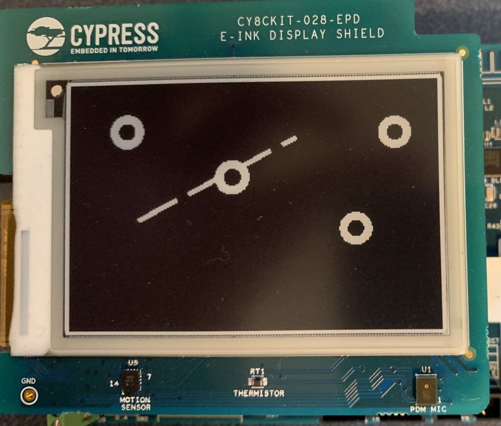
    When I program the screen I get this… which obviously is jacked up.

    But what to do?

    Converting a Color Bitmap to Black and White

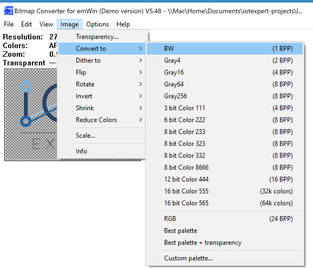
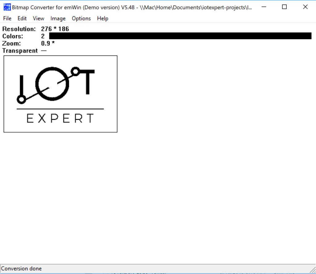
    Well instead of a color image (32 bits-per-pixel) let’s use the Bitmap Converter for emWin (Demo version V5.8 to convert the image to BW.  On the Image –>Covert to –> BW (1BPP)

    After running that I get this. (what happened to my logo?).


    After exporting the new image to a “.c” file I go have a look.  OK it isnt very often that I learn something new about “C”.  But look at this.  Apparently you can represent binary data as “X” and “_” when initializing arrays.  Who knew?

    static GUI_CONST_STORAGE unsigned char _acIOTexpert_Logo_Vertical[] = {
      XXXXXXXX, XXXXXXXX, XXXXXXXX, XXXXXXXX, XXXXXXXX, XXXXXXXX, XXXXXXXX, XXXXXXXX, XXXXXXXX, XXXXXXXX, XXXXXXXX, XXXXXXXX, XXXXXXXX, XXXXXXXX, XXXXXXXX, XXXXXXXX, XXXXXXXX, XXXXXXXX, XXXXXXXX, XXXXXXXX, XXXXXXXX, XXXXXXXX, XXXXXXXX, XXXXXXXX, XXXXXXXX, 
            XXXXXXXX, XXXXXXXX, XXXXXXXX, XXXXXXXX, XXXXXXXX, XXXXXXXX, XXXXXXXX, XXXXXXXX, XXXXXXXX, XXXX____,
    

    When I build the project I find that it is much much smaller.  Thats good.

    =========================================
    == Application CM0+ Memory ==
    =========================================
    code:6560	sram:1724
    
    
    =========================================
    == Application CM4 Memory ==
    =========================================
    code:69744	sram:278492


    And I find that the image occupies 0x196e bytes (also known as 6510 in decimal).  Much better.

    .rodata._acIOTexpert_Logo_Vertical
                    0x000000001000f880     0x196e ./Source/IOTexpert_Logo_Vertical.o

    But, when I program the board, my image is jacked up.  I suppose that I shouldn’t be surprised as thats what the program showed me as well.

    Using GIMP to Fix B/W Conversion

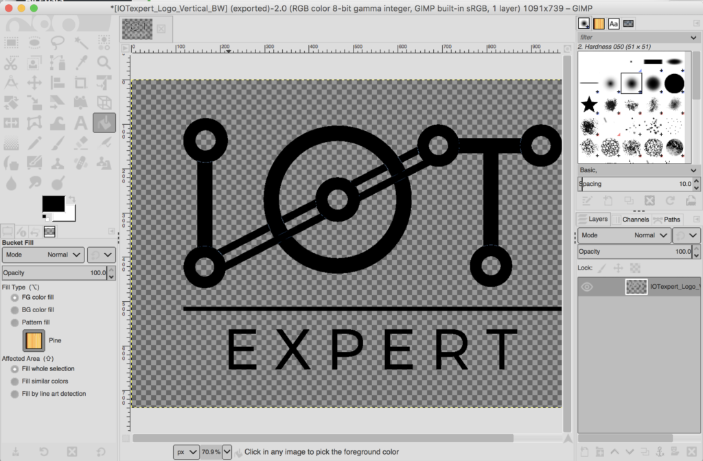
    My lab assistant, Nicholas, looked at the image and said.  The problem is that when you converted it to black and white, the light colors in the logo turned to white instead of black.  OK.  How do I fix it?  Simple, install GIMP and edit the PNG.  GIMP is GNU Image Processor and is a program that acts like Adobe Photoshop.

    Start by opening up the logo and it tell me nearly the same thing as the BitMap converter program.

    On the left side of the screen there is a “bucket” icon which will pour color into regions of the image.  So, to make things work I pour black everywhere there is color.  That little black white thing specifies the foreground and background colors.

    Now I take the file and export it back to an PNG.

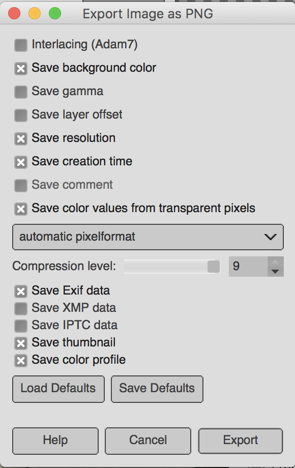
    When you pick “PNG” you need to give it some options.  Which I took also as default.

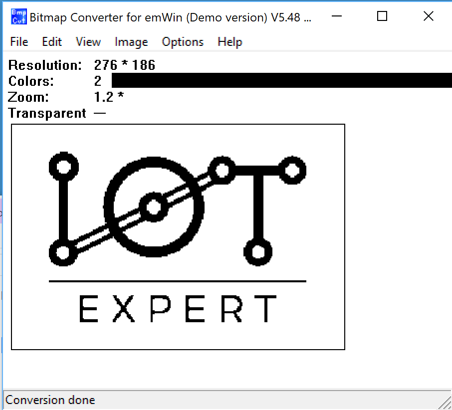
    Now when I open it up in the Bitmap Converter it looks all black and white.  BUT notice that it is still “ARGB”

    So, I convert it to black and white.

    Then I follow the same process to program the development kit. (export C file, copy into project, fix up the extern and build/program).  Excellent.  Now my image is good.

    In the next article I will talk more about the Bitmap format, and colors, and Alpha.  I will then show you how to use some of the other APIs.

    CY8CKIT-028-EPD: How Does The Driver Work?

    Summary

    Before I finish this series there are two more issues which I would like to address.  First, I want to walk you through the schematic and show you how things are connected.  And second, I want to talk about the “Update Scheme”.  Unfortunately, there are a couple of other things that I would like to dig into, but for now this article will be the last.  But, I will leave a few links at the end of the article which will give you a hint about other things that I might be interested in.

    Electrical Interface

    If you follow back through the previous articles you will notice that there are several different pins.  Here is the pin assignment from PSoC Creator.

    But what do they do?  If you look at the list you will see that four of them are to control the SPI interface to the G2 display driver. (miso, mosi, sclk, CY_EINK_Ssel).  The rest of them Ill go one by one through.

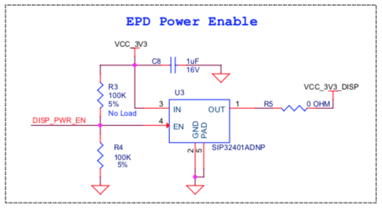
    First is the pin called “CY_EINK_DispEn”.  This pin really should have been called “DISP_PWR_EN” so that it matched the actual shield schematic.  This is a digital output pin which is connected to a Vishay sip32401a 1.1 V to 5.5 V, Slew Rate Controlled Load Switch.  Simply a power switch for the display.  Notice in the schematic that there is a 100K pulldown resistor connected to the enable which means that by default the power is off to the display.  Also notice that R3 is a “No Load” pullup resistor.  You could remove R4 and load R3 to make the power on by default… which I don’t think that you would actually ever do as if you are using an EPD you probably care about power.

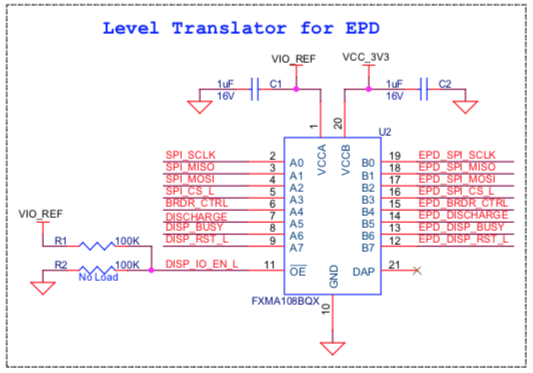
    The next pin is called “CY_EINK_DispIoEn”.  This is a digital output pin which is connected to “DISP_IO_EN_L” on the shield.  This is simply the I/O enable of a Fairchild FXMA108BQX level shifter.  This allows the PSoC to run at lower voltages (e.g. 1.8v) than the 3.3v required by the EPD G2 driver chip.  This would also enable a chip to run at a higher voltage (e.g. 5V) if you were using a 5V capable PSoC (e.g. all of the PSoC 4s).  The schematic uses the same pullup/down scheme that was used on the power switch above.

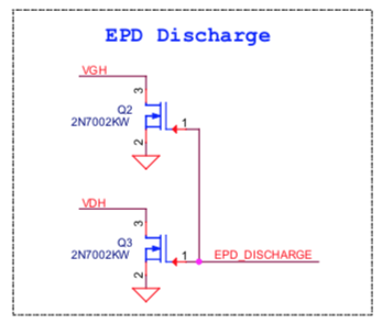
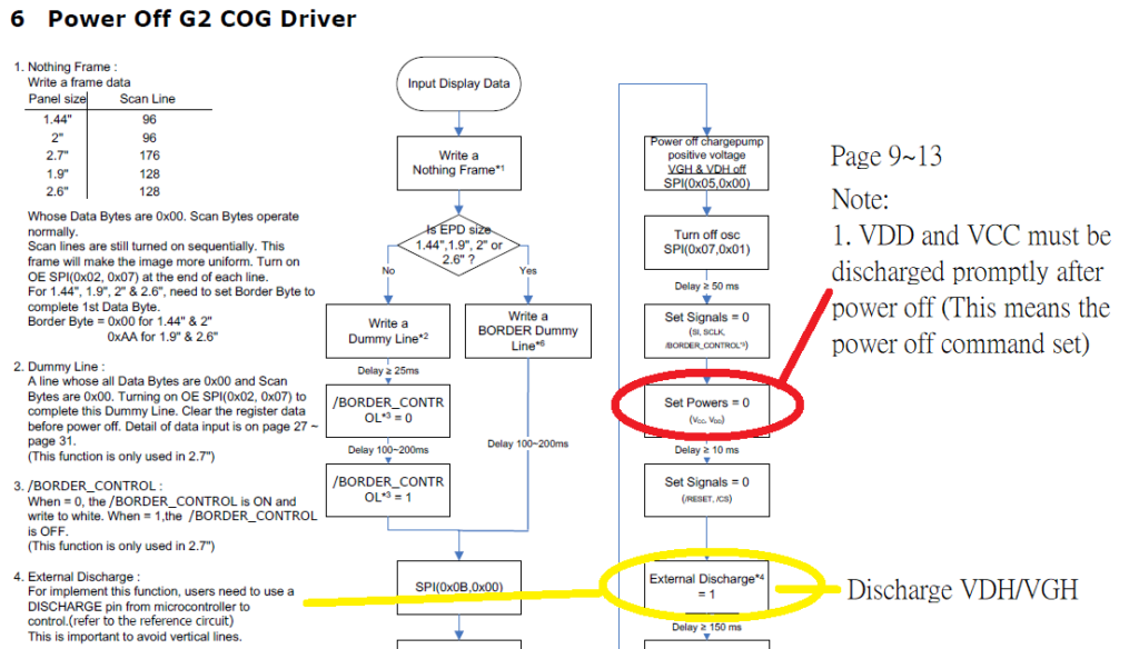
    The next pin is called “CY_EINK_Discharge” and is a digital output from the PSoC.  Notice that when the PSoC drives this pin high that it will enable two power transistors and will short “VGH” and “VDH” to ground.

    If you read the “E-paper Display COG Driver Interface Timing for 1.44”,1.9”,2”,2.6” and 2.7” EPD with G2 COG and Aurora Mb Film” document you will see this note:

    And a bit later on in the documented you will see this logic diagram.

    According to the data sheet, Vgh is driven to >12v and Vdh>8v by a charge pump while talking to the screen.  What I don’t understand is why the note says to drive “Vdd and Vcc” to ground when their schematic says Vdh and Vgh.  I am assuming that the note is an error and the schematic is correct, but Ill send them a note and ask. [edit: I got a quick response from an excellent FAE at Pervasive… with this answer]

    “No, the expression of Note 1 about Vcc/Vdd, it means the power off command set. You can also refer to Power off sequence in section 6 on page 34 of 4P018-00 as follows”

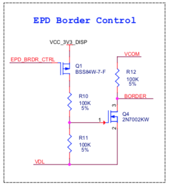
    The last digital I/O pin is called “CY_EINK_Border”.  This pin is connected to the note “EPD_BRDR_CTRL” on this little circuit on the shield.

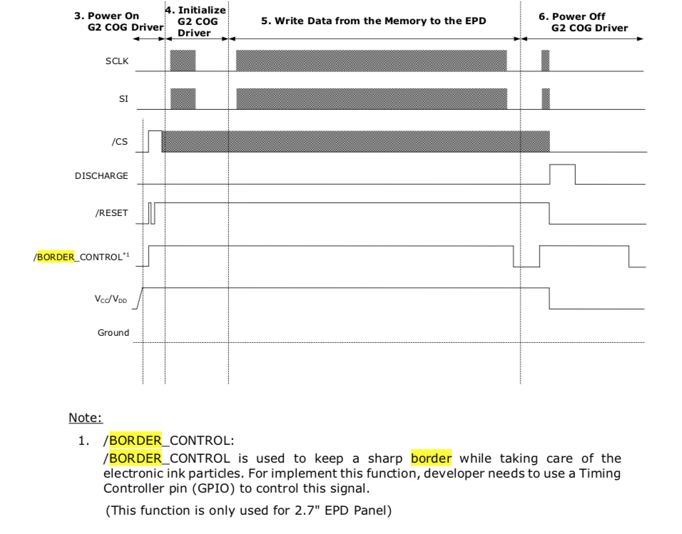
    If you look in the documentation you will see this note:

    And when you look at the timing diagram you see this which shows that after you have update the frame, that you need to do a low, high, low of the border to make it white again.

    This transition is handled for you by the function “Pv_EINK_HardwarePowerOff” function… which I chopped out a little bit of to show the border control.

    pv_eink_status_t Pv_EINK_HardwarePowerOff(void)
    {
    .....
        
        /* After E-INK updates, the border color may degrade to a gray level that is not
        as white as the active area. Toggle the Border pin to avoid this phenomenon. */
        CY_EINK_Delay(PV_EINK_DUMMY_LINE_DELAY);
        CY_EINK_BorderLow;
        CY_EINK_Delay(PV_EINK_BOARDER_DELAY);
        CY_EINK_BorderHigh;
    
    ...
    turn of the G2    
    ....
    
        /* Detach SPI and disable the load switch connected to E-INK display's Vcc */
        Cy_EINK_DetachSPI();
        CY_EINK_TurnOffVcc;
        
        /* Return the pins to their default (OFF) values*/
        CY_EINK_BorderLow;
        CY_EINK_Delay(PV_EINK_CS_OFF_DELAY);
        CY_EINK_CsLow;
        CY_EINK_RstLow;
        CY_EINK_DischargeHigh;
        CY_EINK_Delay(PV_EINK_DETACH_DELAY);
        CY_EINK_DischargeLow;
        
        /* If all operations were completed successfully, send the corresponding flag */
        return(PV_EINK_RES_OK);
    }

    Update Scheme

    If you look at the original picture that I posted,  you can see that “Hassane…” text.  But if you look closely you can see a “ghost image” of the Cypress logo in the background.  Why is this?

    It turns out that Pervasive has three schemes for updating the screen they are called

    1. Four stage
    2. Two stage
    3. Partial

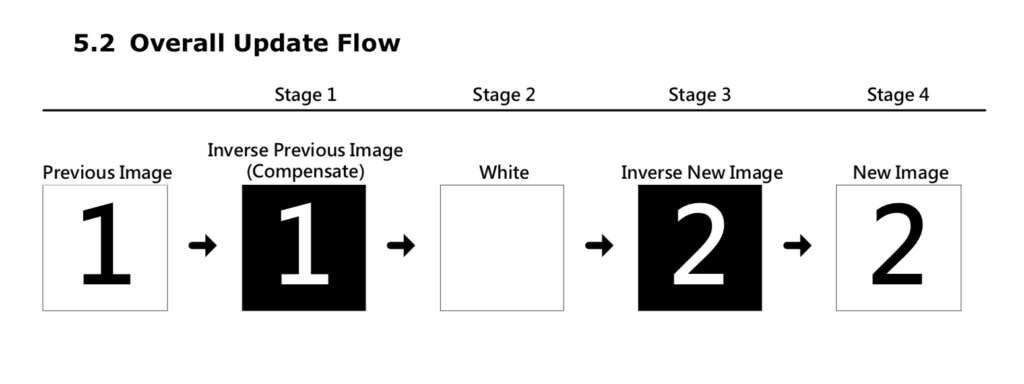
    The four stage update actually writes four complete images on the screen as below (here is the picture from the Pervasive document)

    The purpose of this four stage update is to reduce the ghost images which remain from the previous updates.  Remember that the cool part about these screens is that there are crystals that flip from white to black and back… and once they are flipped you do not need to maintain power to keep them flipped.  The bad news is that they really want to stay flipped which causes Ghosting.

    So why can you see the old image of the Cypress logo?  Simple,  when the four-stage update happened, I had just programmed the kit which means that my program had no idea what was on the screen from before.  This made stage 1 not work correctly because it had to assume all white.

    The next question is what is the problem with the four-stage update?  Well it takes a while (like about 2 seconds) on the 2.7″ screen.  And because it writes 4 times it also consumes more power.  Pervasive also says that you can do a two-stage update with just stage 1 and stage 4 from above.  In my case this cuts the time in about half.

    Finally you can also do a “partial” update.  I tried this and it didn’t work very well for my demo application which massively changes the screen from screen to screen.  But, it does seem to work pretty well for a series of updates to the same reigon (like this counter).  Here is a video I made showing Partial, Two and Four stage updates.   In addition our API lets you turn the power on/off for the G2 Driver – called “power cycle”.  I used that as a variable as well.

    Terms of Art

    EPD – Electrophoretic Display

    eTC – external timing control

    iTC – internal timing control

    G2 COG – Display Controller Chip… Chip on Glass

    FPL – Front Plane Laminate (of which Aurora ma and mb are two types)

    Aurora ma – Wide Temperature film

    Aurora mb – Low power

    E2271CS021 – Aurora mb 2.71″ EPD Panel – on CY8CKIT-028-EPD

    E2271BS021 – Aurora ma 2.71″ EPD Panel

    References

    mbed add http://os.mbed.com/users/dreschpe/code/EaEpaper/

    http://www.pervasivedisplays.com/kits/ext2_kit

    https://www.nayuki.io/page/pervasive-displays-epaper-panel-hardware-driver

    https://github.com/nayuki/Pervasive-Displays-epaper-driver

    https://github.com/repaper/gratis

    https://github.com/aerialist/repaper_companion

    https://www.paulschow.com/2017/02/pervasive-displays-epd-extension-kit.html

    https://embeddedcomputing.weebly.com/pervasive-displays-e-paper-epd-extension-kit-gen-2.html

    CY8CKIT-028-EPD Better Timing

    Summary

    In the first article of this series I talked about how to make the CY8CKIT-028-EPD EINK Shield work with PSoC 6 and Modus Toolbox 1.1. In the second article I improved the interface and talked about the PSoC 6 clocking system.  In this article I want to address the timing system in the EINK firmware.  You might recall that I used one of the Timer-Counter-Pulse-Width-Modulator blocks a.k.a the TCPWM inside of the PSoC 6 as a Timer for updating the EINK Screen.  Using this timer was a bit of a waste as the CM4 already has a timer built into the device called the SysTick timer.  Moreover, the SysTick timer is connected to the FreeRTOS timing system which provides you APIs to talk to it.  For this article I will talk about:

    • ARM SysTick
    • Cypress PDL and SysTick
    • FreeRTOS and SysTick
    • Make a new project & copy the files
    • Use the FreeRTOS timing system to measure the speed increase of the updated SPI
    • Remove the hardware timer & replace with the RTOS timer.

    ARM SysTick

    The ARM Cortex-M MCUs have an option to include a 24-bit timer called SysTick.  As best I can tell, every MCU maker always chooses to have the SysTick option built in.   Certainly the PSoC 4 and PSoC 6 family all have it built in.   But how do you talk to it?  Well, my buddy Reinhard Keil decided that it was silly for everyone to create a different method for interacting with standard ARM peripherals so he created the Cortex Microcontroller Software Interface Standard (CMSIS)

    CMSIS defines two things that you need to do to make the SysTick timer work.  First, you need to create a function called EXACTLY “SysTick_Handler”.  This function gets loaded into the vector table of your program as the interrupt handler for the SysTick interrupt.  As such the function prototype is “void SysTick_Handler(void)”.  The second thing that you need to do is initialize how often the timer should be called.  You do this with the CMSIS call:

    SysTick_Config(SystemCoreClock/1000);

    It is interesting to note that the symbol SystemCoreClock is also defined by CMSIS as the frequency of the clock.  So the above call would setup the SysTick to be called every 1Ms (that is why there is a divide by 1000).

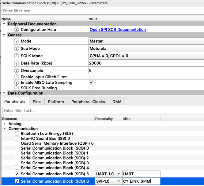
    Here is an example I created starting with the BlinkyLED example project.  After I created the project, I added the kitprog uart (which is SCB5) and I added the Retarget I/O middleware.

    #include "cy_pdl.h"
    #include "cycfg.h"
    #include <stdio.h>
    
    volatile uint32_t count;
    
    void SysTick_Handler(void)
    {
    	count += 1;
    }
    cy_stc_scb_uart_context_t kitprog_context;
    
    int main(void)
    {
    	Cy_SCB_UART_Init(kitprog_HW,&kitprog_config,&kitprog_context);
    	Cy_SCB_UART_Enable(kitprog_HW);
        /* Set up internal routing, pins, and clock-to-peripheral connections */
        init_cycfg_all();
        
        SysTick_Config(SystemCoreClock/1000);
    
        /* enable interrupts */
        __enable_irq();
    
        for (;;)
        {
        		printf("Test count=%d\n",(int)count);
            Cy_GPIO_Inv(LED_RED_PORT, LED_RED_PIN); /* toggle the pin */
            Cy_SysLib_Delay(1000/*msec*/);
        }
    }
    

    Don’t forget to setup the standard i/o by modifying stdio_user.h

    #include "cycfg.h"
    /* Must remain uncommented to use this utility */
    #define IO_STDOUT_ENABLE
    #define IO_STDIN_ENABLE
    #define IO_STDOUT_UART      kitprog_HW
    #define IO_STDIN_UART       kitprog_HW

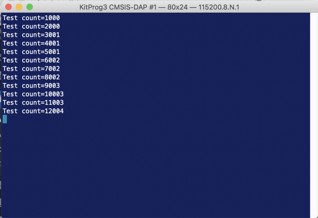
    When you run the program above you should get something like this:

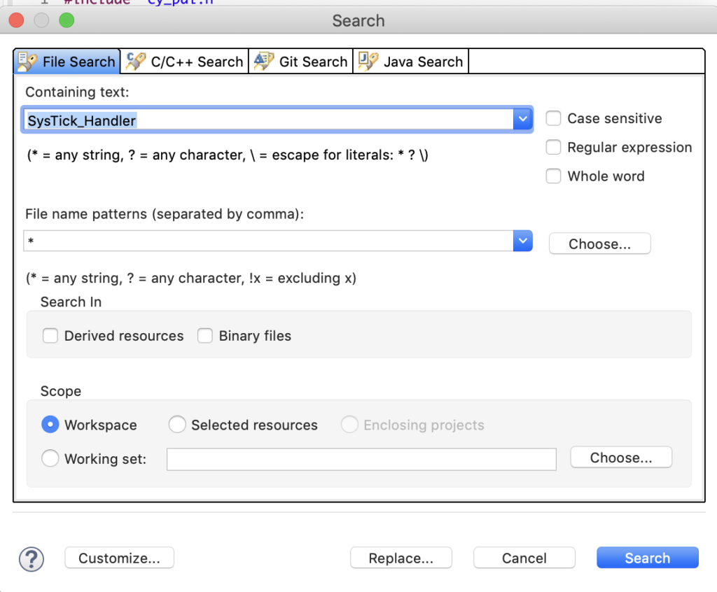
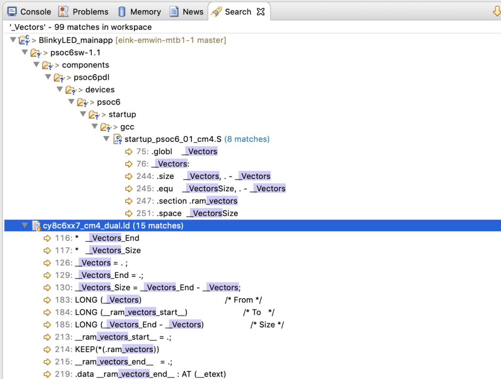
    One interesting question is HOW does the function SysTick_Handler get into the vector table?  Well if you run an eclipse search (type ctrl-h)

    You will find it in an assembly language file called “startup_psoc6_01_cm4.s”

    Double click on the file and you can see the Vector table.

    __Vectors:
        .long    __StackTop            /* Top of Stack */
        .long    Reset_Handler         /* Reset Handler */
        .long    CY_NMI_HANLDER_ADDR   /* NMI Handler */
        .long    HardFault_Handler     /* Hard Fault Handler */
        .long    MemManage_Handler     /* MPU Fault Handler */
        .long    BusFault_Handler      /* Bus Fault Handler */
        .long    UsageFault_Handler    /* Usage Fault Handler */
        .long    0                     /* Reserved */
        .long    0                     /* Reserved */
        .long    0                     /* Reserved */
        .long    0                     /* Reserved */
        .long    SVC_Handler           /* SVCall Handler */
        .long    DebugMon_Handler      /* Debug Monitor Handler */
        .long    0                     /* Reserved */
        .long    PendSV_Handler        /* PendSV Handler */
        .long    SysTick_Handler       /* SysTick Handler */

    But how do the _Vectors get into the right place?  Well? run the search again and you will find that the linker script (which Cypress created) for your project has the definition.

    When you look in the linker script you can see that it is installed at the top of the flash

        {
            . = ALIGN(4);
            __Vectors = . ;
            KEEP(*(.vectors))
            . = ALIGN(4);
            __Vectors_End = .;
            __Vectors_Size = __Vectors_End - __Vectors;
            __end__ = .;
    
            . = ALIGN(4);
            *(.text*)
    
            KEEP(*(.init))
            KEEP(*(.fini))
    
            /* .ctors */
            *crtbegin.o(.ctors)
            *crtbegin?.o(.ctors)
            *(EXCLUDE_FILE(*crtend?.o *crtend.o) .ctors)
            *(SORT(.ctors.*))
            *(.ctors)
    
            /* .dtors */
            *crtbegin.o(.dtors)
            *crtbegin?.o(.dtors)
            *(EXCLUDE_FILE(*crtend?.o *crtend.o) .dtors)
            *(SORT(.dtors.*))
            *(.dtors)
    
            /* Read-only code (constants). */
            *(.rodata .rodata.* .constdata .constdata.* .conststring .conststring.*)
    
            KEEP(*(.eh_frame*))
        } > flash

    And the CM4 flash is defined to start at 0x100002000

    MEMORY
    {
        /* The ram and flash regions control RAM and flash memory allocation for the CM4 core.
         * You can change the memory allocation by editing the 'ram' and 'flash' regions.
         * Note that 2 KB of RAM (at the end of the RAM section) are reserved for system use.
         * Using this memory region for other purposes will lead to unexpected behavior.
         * Your changes must be aligned with the corresponding memory regions for CM0+ core in 'xx_cm0plus.ld',
         * where 'xx' is the device group; for example, 'cy8c6xx7_cm0plus.ld'.
         */
        ram               (rwx)   : ORIGIN = 0x08002000, LENGTH = 0x45800
        flash             (rx)    : ORIGIN = 0x10002000, LENGTH = 0xFE000
    
        /* This is a 32K flash region used for EEPROM emulation. This region can also be used as the general purpose flash.
         * You can assign sections to this memory region for only one of the cores.
         * Note some middleware (e.g. BLE, Emulated EEPROM) can place their data into this memory region.
         * Therefore, repurposing this memory region will prevent such middleware from operation.
         */
        em_eeprom         (rx)    : ORIGIN = 0x14000000, LENGTH = 0x8000       /*  32 KB */
    
        /* The following regions define device specific memory regions and must not be changed. */
        sflash_user_data  (rx)    : ORIGIN = 0x16000800, LENGTH = 0x800        /* Supervisory flash: User data */
        sflash_nar        (rx)    : ORIGIN = 0x16001A00, LENGTH = 0x200        /* Supervisory flash: Normal Access Restrictions (NAR) */
        sflash_public_key (rx)    : ORIGIN = 0x16005A00, LENGTH = 0xC00        /* Supervisory flash: Public Key */
        sflash_toc_2      (rx)    : ORIGIN = 0x16007C00, LENGTH = 0x200        /* Supervisory flash: Table of Content # 2 */
        sflash_rtoc_2     (rx)    : ORIGIN = 0x16007E00, LENGTH = 0x200        /* Supervisory flash: Table of Content # 2 Copy */
        xip               (rx)    : ORIGIN = 0x18000000, LENGTH = 0x8000000    /* 128 MB */
        efuse             (r)     : ORIGIN = 0x90700000, LENGTH = 0x100000     /*   1 MB */
    }

    And when you look at the linker MAP file which is in your project Debug/BlinkyLED_mainapp.map you will see that the vectors end up in the right place.

    .text           0x0000000010002000     0x5de4
                    0x0000000010002000                . = ALIGN (0x4)
                    0x0000000010002000                __Vectors = .
    

    Cypress SysTick

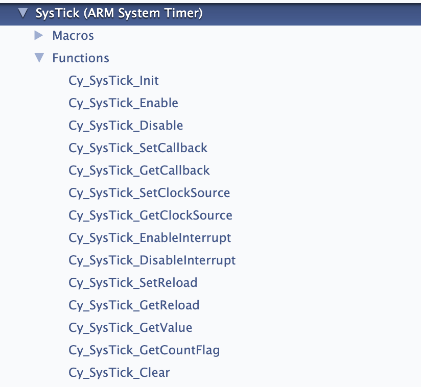
    Now if you happen to be reading the PDL documentation on Saturday afternoon you might notice that there is a section of the documentation called “SysTick”.  And when you click it you will find this:

    And you might ask yourself “What the hell.. those aren’t CMSIS functions?”  Well in typical Cypress fashion we created an extension to SystTick.  It does two basic things

    1. Lets you pick different clock sources for the SysTick timer
    2. Lets you setup multiple callbacks to make it easier to trigger multiple functions in your system

    For this example I modified the previous project by commenting out the CMSIS calls.  And I use the Cy_SysTick calls.

    #include "cy_pdl.h"
    #include "cycfg.h"
    #include <stdio.h>
    
    volatile uint32_t count;
    cy_stc_scb_uart_context_t kitprog_context;
    
    #if 0
    void SysTick_Handler(void)
    {
    	count += 1;
    }
    #endif
    
    void MyHander(void)
    {
    	count += 1;
    }
    
    int main(void)
    {
    	Cy_SCB_UART_Init(kitprog_HW,&kitprog_config,&kitprog_context);
    	Cy_SCB_UART_Enable(kitprog_HW);
        /* Set up internal routing, pins, and clock-to-peripheral connections */
        init_cycfg_all();
    
        Cy_SysTick_Init ( CY_SYSTICK_CLOCK_SOURCE_CLK_CPU, 100000000/1000); // CPU Freq divide by 1000 makes MS
        Cy_SysTick_SetCallback(0,MyHander); // Slot 0
        Cy_SysTick_Enable();
        
    //    SysTick_Config(SystemCoreClock/1000);
    
        /* enable interrupts */
        __enable_irq();
    
        for (;;)
        {
        		printf("Test count=%d\n",(int)count);
            Cy_GPIO_Inv(LED_RED_PORT, LED_RED_PIN); /* toggle the pin */
            Cy_SysLib_Delay(1000/*msec*/);
        }
    }
    

    When you look at this program you might ask where I got the “100000000/1000″…. and if Hassane is reading he will ask WHY DIDN’T YOU COMMENT IT.   The answer to the first question is that it is the CPU Frequency divided by 1000 to get a millisecond timer.

    As to the second question… the answer is … “I just did” 🙂

    There is probably some MACRO for those values… but I just don’t know what they are… and I suppose that I should go look… but…

    And finally the “// slot 0”  means that it uses the first of 5 slots… in other words places where you can store a callback.

    FreeRTOS usage of SysTick

    The FreeRTOS by default uses the SysTick timer to cause the scheduler to run.  And it does this by using the CMSIS interface… well because everyone needs to do their own thing, it actually lets you define the function.  Here is a clip out of FreeRTOSConfig.h where it defines the actual function name as xPortSysTickHandler.

    /* Definitions that map the FreeRTOS port interrupt handlers to their CMSIS
    standard names - or at least those used in the unmodified vector table. */
    #define vPortSVCHandler     SVC_Handler
    #define xPortPendSVHandler  PendSV_Handler
    #define xPortSysTickHandler SysTick_Handler

    And when you look around (using find) you will find it in the file port.c.

    void xPortSysTickHandler( void )
    {
    	/* The SysTick runs at the lowest interrupt priority, so when this interrupt
    	executes all interrupts must be unmasked.  There is therefore no need to
    	save and then restore the interrupt mask value as its value is already
    	known. */
    	portDISABLE_INTERRUPTS();
    	{
    		/* Increment the RTOS tick. */
    		if( xTaskIncrementTick() != pdFALSE )
    		{
    			/* A context switch is required.  Context switching is performed in
    			the PendSV interrupt.  Pend the PendSV interrupt. */
    			portNVIC_INT_CTRL_REG = portNVIC_PENDSVSET_BIT;
    		}
    	}
    	portENABLE_INTERRUPTS();
    }

    And if you look in vTaskStartScheduler you will find that it calls the function vPortSetupTimerInterrupt where it sets up interrupt manually.

    /*
     * Setup the systick timer to generate the tick interrupts at the required
     * frequency.
     */
    __attribute__(( weak )) void vPortSetupTimerInterrupt( void )
    {
    	/* Calculate the constants required to configure the tick interrupt. */
    	#if( configUSE_TICKLESS_IDLE == 1 )
    	{
    		ulTimerCountsForOneTick = ( configSYSTICK_CLOCK_HZ / configTICK_RATE_HZ );
    		xMaximumPossibleSuppressedTicks = portMAX_24_BIT_NUMBER / ulTimerCountsForOneTick;
    		ulStoppedTimerCompensation = portMISSED_COUNTS_FACTOR / ( configCPU_CLOCK_HZ / configSYSTICK_CLOCK_HZ );
    	}
    	#endif /* configUSE_TICKLESS_IDLE */
    
    	/* Stop and clear the SysTick. */
    	portNVIC_SYSTICK_CTRL_REG = 0UL;
    	portNVIC_SYSTICK_CURRENT_VALUE_REG = 0UL;
    
    	/* Configure SysTick to interrupt at the requested rate. */
    	portNVIC_SYSTICK_LOAD_REG = ( configSYSTICK_CLOCK_HZ / configTICK_RATE_HZ ) - 1UL;
    	portNVIC_SYSTICK_CTRL_REG = ( portNVIC_SYSTICK_CLK_BIT | portNVIC_SYSTICK_INT_BIT | portNVIC_SYSTICK_ENABLE_BIT );
    }

    And what is really cool is that when you look in FreeRTOSConfig.h you can see that it uses the CMSIS macro “SystemCoreClock” and that it is configured to have a 1MS callback.

    #define configCPU_CLOCK_HZ                      SystemCoreClock
    #define configTICK_RATE_HZ                      1000u

    So, why did I look at all of that?  Well simple, each time that the SysTick interrupt is called, the FreeRTOS adds 1 to a count…. which you can get access to by calling “xTaskGetTickCount”.  Nice.

    I think that is enough background… so let’s:

    Make a New Project

    I want to start by creating a copy of the project from the previous article (so that alls yall can see the progression of code changes).  In the previous article I walked you step-by-step through creating and copying a project.  Here is a summary of the step you need to take.  If you want to see the details please look at the last article.

    1. Make a new project
    2. Copy design.modus
    3. Add the middleware (FreeRTOS, Segger Core OS NoTouch & Soft FP,Segger BitPlains, Retarget I/O)
    4. Copy all of the files from the source directory
    5. Update the Include paths with the “eInk Library” and “emWin_Config”

    After making all of these changes I will have a project in my workspace called “EHKEinkTiming”.  I would recommend before you go further that you build and program to make sure that everything is still working.

    Measure the SPI Speed Increase

    All of the action to dump the frame buffer onto the EINK display happens in the function UpdateDisplay in the file eInkTask.c.  In the code below you can see that I ask FreeRTOS what the count is before I dump the display, then what the count is after it is done.

    void UpdateDisplay(cy_eink_update_t updateMethod, bool powerCycle)
    {
        /* Copy the EmWin display buffer to imageBuffer*/
        LCD_CopyDisplayBuffer(imageBuffer, CY_EINK_FRAME_SIZE);
    
        uint32_t startCount = xTaskGetTickCount();
        /* Update the EInk display */
        Cy_EINK_ShowFrame(imageBufferCache, imageBuffer, updateMethod, powerCycle);
        uint32_t endCount = xTaskGetTickCount();
        printf("Update Display Time = %d\n",(int)(endCount - startCount));
    
        /* Copy the EmWin display buffer to the imageBuffer cache*/
        LCD_CopyDisplayBuffer(imageBufferCache, CY_EINK_FRAME_SIZE);
    }

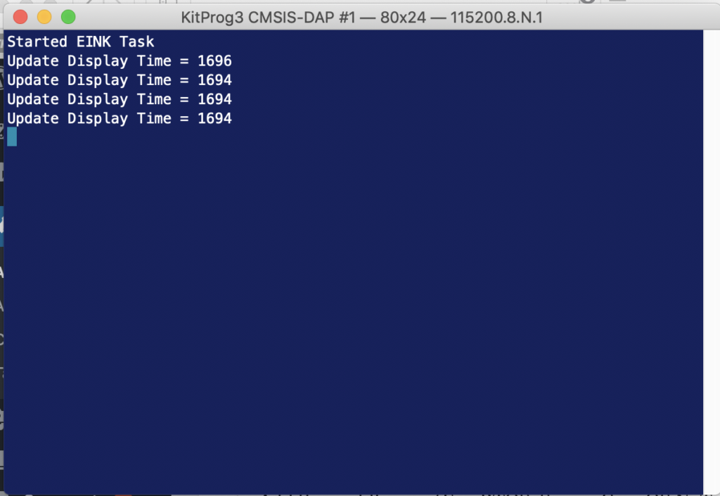
    When I run the updated program I find that it takes about 1.7 seconds to update the screen.

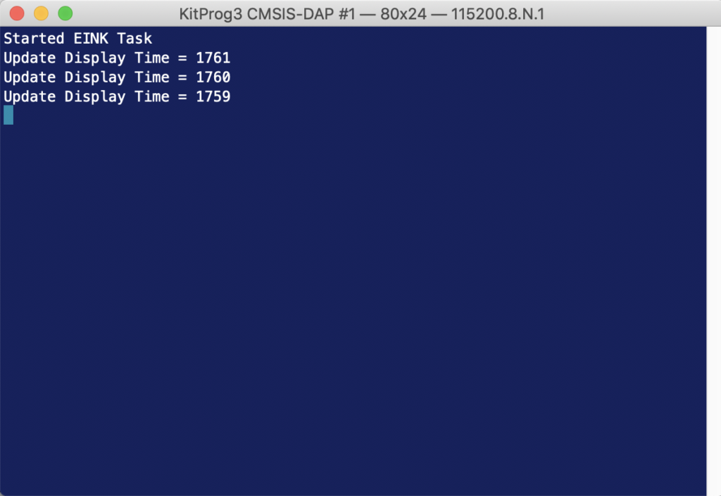
    Then I go back and modify the original program (before the SPI fixes) to see how long it takes…

    And yes if you can do math, which I’m sure everyone who has read this far can, you will notice that I only sped things up by 65 Milliseconds… which means you need to call bullshit on my original declaration that it was noticeably faster.  Oh well at least I learned a bunch about the clock system.

    Remove the HW timer & Update the EINK Driver

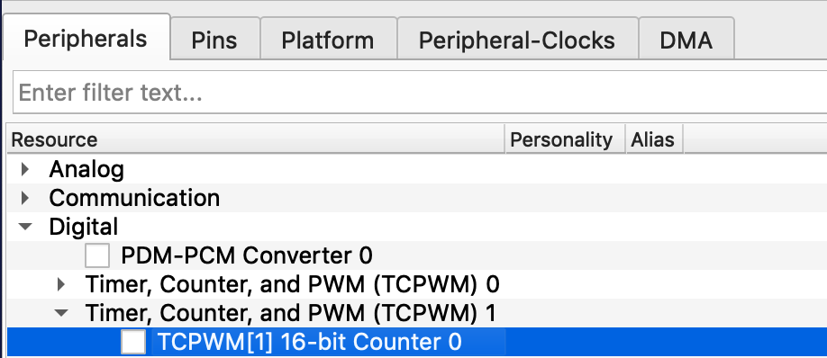
    OK now that we have the hang of SysTick, it is clear that we don’t need the hardware timer that we put into the first project, so let’s get it out of there.  Start by running design.modus and removing the timer.  Just click the checkbox on “TCPWM[1]…” to turn it off.  Then press save.

    If you hit compile you will find a whole bunch of errors… but they are all in four functions inside of cy_eink_psoc_interface.c.   Specifically

    • Cy_EINK_TimerInit
    • Cy_EINK_GetTimeTick
    • Cy_EINK_TimerStop

    To fix them Ill first create a global static variable called “timerCount”

    static uint32_t timerCount;
    

    Then update Cy_EINK_TimerInit to just store the current FreeRTOS timer value in my new global variable.

    void Cy_EINK_TimerInit(void)
    {   
    	timerCount = xTaskGetTickCount();
    }
    

    Next update Cy_EINK_GetTimeTick to return the number of ticks since the timer was initialized.

    uint32_t Cy_EINK_GetTimeTick(void)
    {
    	    /* Return the current value of time tick */
        return(xTaskGetTickCount()-timerCount);
    }
    

    Finally, make the TimerStop function do… well… nothing.

    void Cy_EINK_TimerStop(void)
    {
    }
    

    When I build and program… my project is off to the races without the hardware timer.

    In the next article Ill have a look at the EINK datasheet and driver to look into how it works.

    CY8CKIT-028 Eink Mo-better

    Summary

    In the last article, I walked you through the process of making the CY8CKIT-028 EINK shield work on the PSoC 6 and Modus Toolbox 1.1.  The article got to be a bit out of control in terms of length so I decided to split it into four pieces.  In this article, the second part, I will make updates to the project to increase the overall speed of updating the display.  This will require a dive into the PSoC 6 clocking system.

    This article will contain the following steps/commentary:

    1. Make a new project based on the previous example
    2. Examine the PSOC 6 clocking system
    3. Look at what is required to speed up the SPI & make the changes
    4. Update, program and test the faster clock

    Make a new project

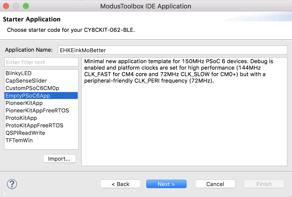
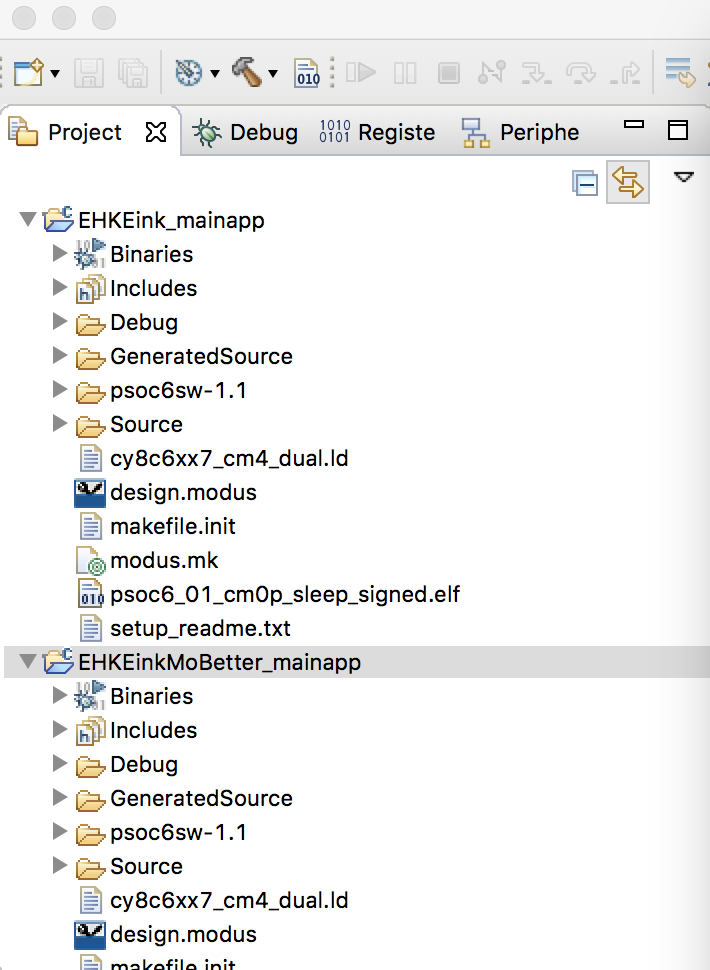
    I really wish I knew how to copy a Modus Toolbox project, and I suppose that is something I should probably figure out.  But, for this article, Ill create a new project, setup the middleware and copy in the files from the previous project.  Here we go:

    First, create a new project for the CY8CKIT-062-BLE


    Then copy the “design.modus” from the previous project and paste it into the new project.  You can do with ctrl-c and ctrl-v.  Remember, the design.modus file is just an xml file that contains all of the configuration information for your project.

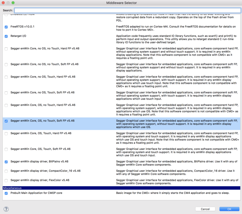
    Next, select middleware for your project including FreeRTOS, Retarget I/O and the two Segger libraries.

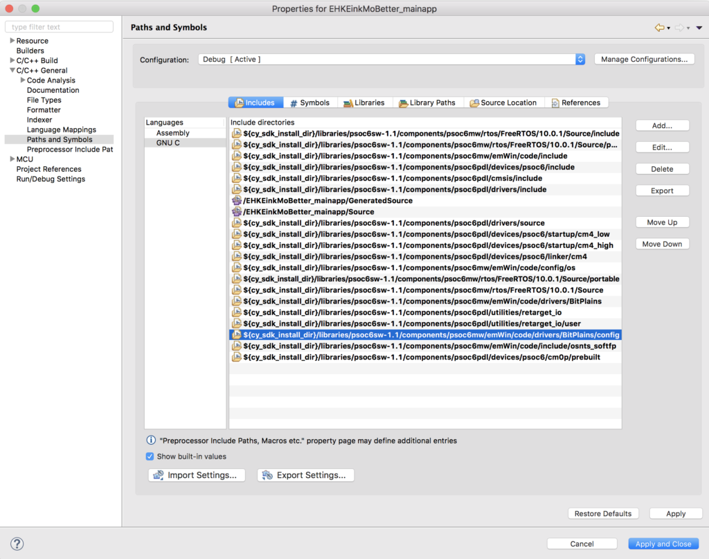
    Recall from the previous article that you need to remove the incorrectly included path for …Bitplains/config.  To do this right click on the project, select settings, pick paths and symbols then click on the wrong directory path and hit Delete.

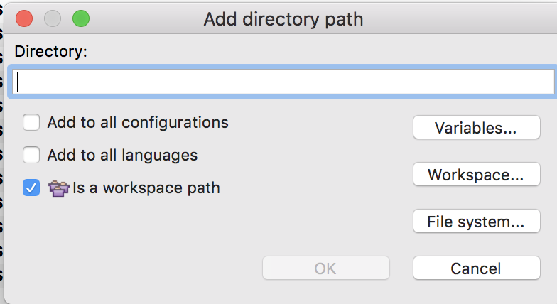
    Now you need to add the paths for “eInk Library” and the “emWin_Config”.   To do this click the “Add…” button.  In the screen below you can see that I clicked “Is a workspace path” which will make it a relative path (i.e. not hardcoded).  Now click “Workspace…”

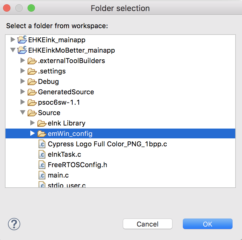
    Then select the “emWin_Config” folder

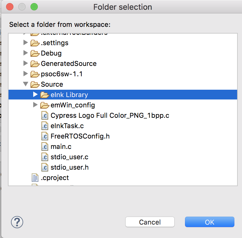
    Then do the same process again for the eInk Library.

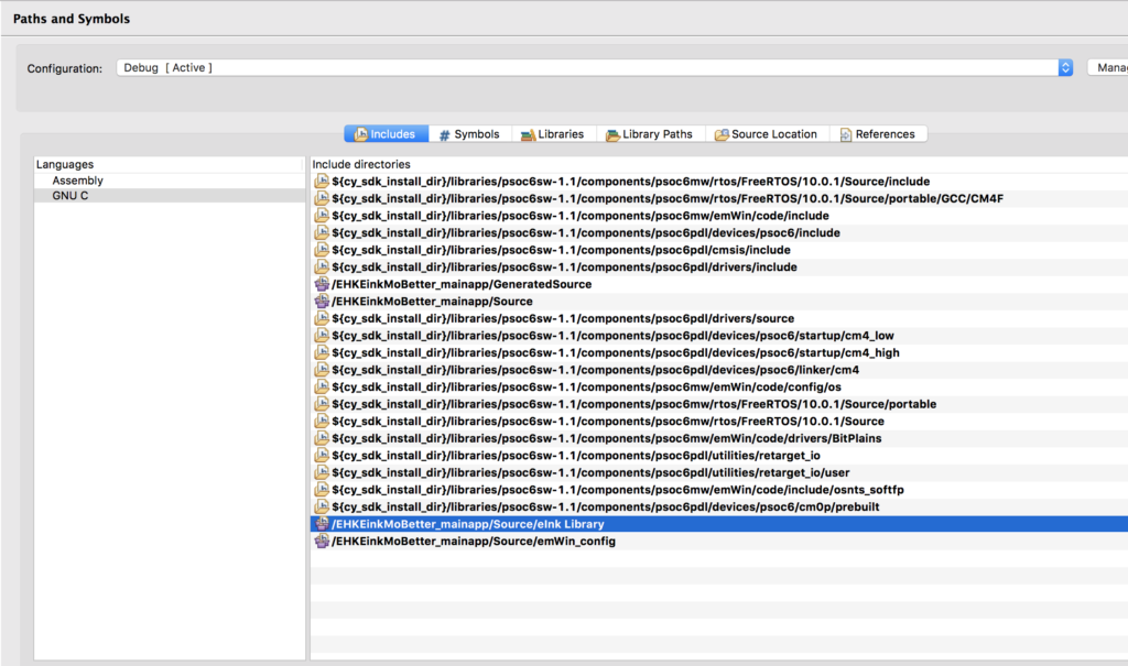
    Now your Include path should look something like this:

    The next thing to do is copy your c and h files from the previous project.  I just use ctrl-c and ctrl-v


    Finally build it and make sure everything is working.

    How does the clocking in the PSoC 6 work?

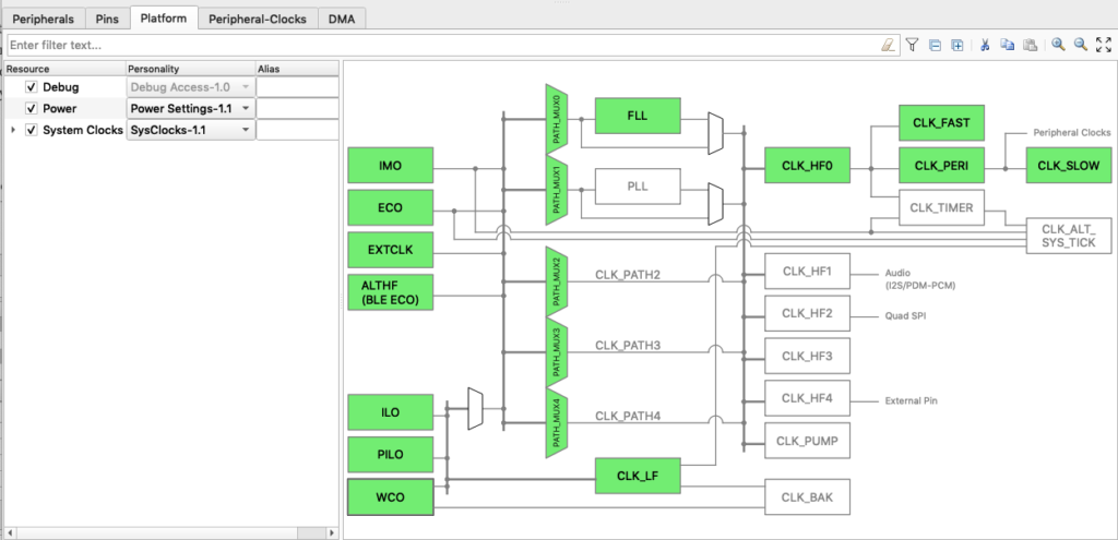
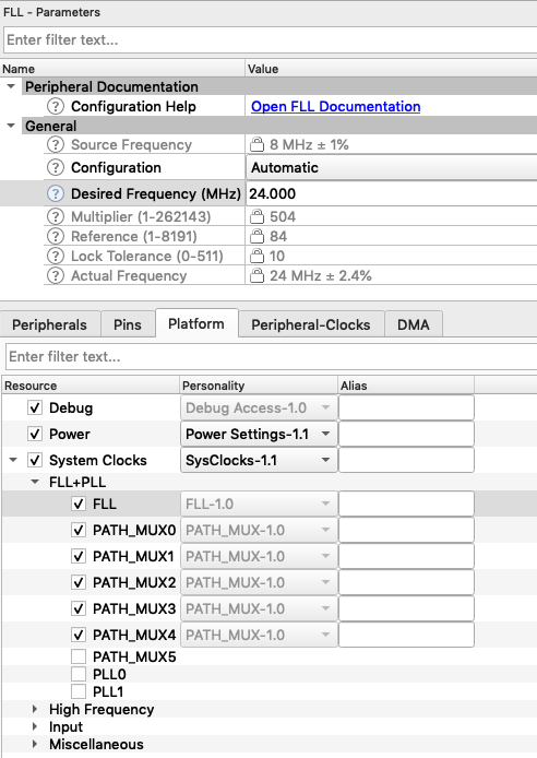
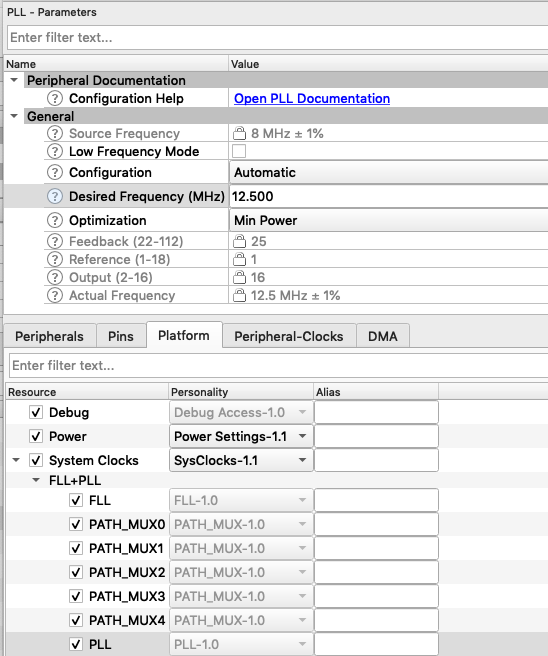
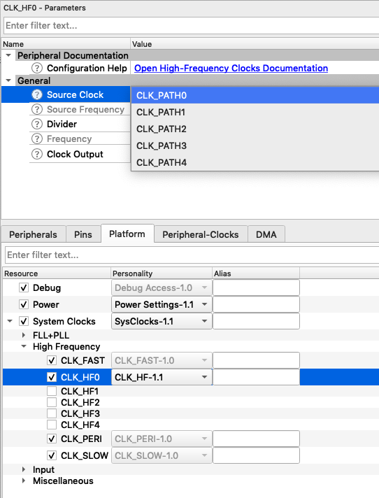
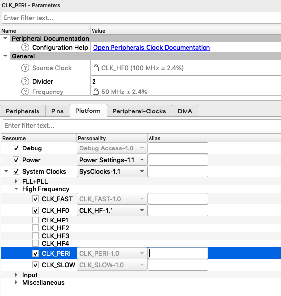
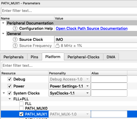
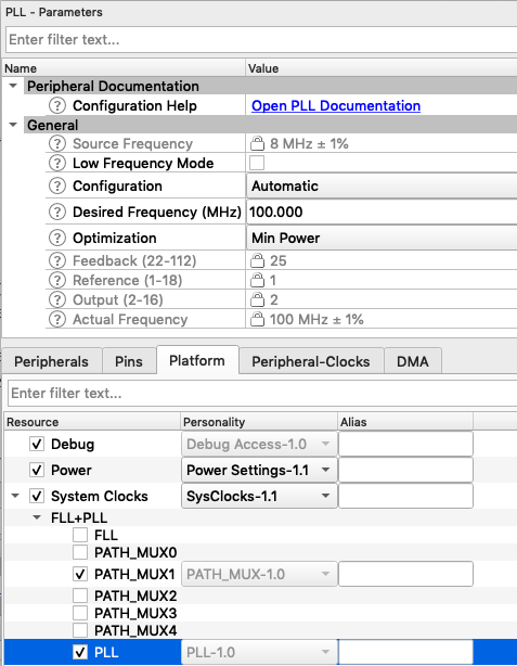
    Before we can fix the SPI speed problem we should have a closer look at the PSoC 6 clocking system.  Let’s start this by double clicking the design.modus in order to open up the device configurator.  When you click on the “Platform” you should see a window that looks like this.

    On the far left side of the picture you can see the “Input” section.  These are reference sources that will drive all of the clock signals in the chip.  This includes

    • IMO – Internal Main Oscillator which is an 8Mhz 1% precision RC Oscillator (requires no external components)
    • ECO – External Crystal Oscillator which will drive a precision crystal for a more accurate clock.  This is sometimes called the “Megahertz clock”
    • External Clock – a pin that will take a clock signal from outside the chip
    • ILO – Internal Low Speed Oscillator – a 32Khz +- 30% (yes 30%) very low power very slow oscillator for generating wakeup signals etc.
    • WCO – Watch Crystal Oscillator – a very precise circuit for driving a 32Khz watch crystal for very accurate clocks

    You can configure each of the “Input” clock sources on the “Input” section of the “System Clock”.  In the picture below you can see that I have enabled all of the clock sources and I’m updating the parameters on the ECO.  In the picture above all of the input sources that are enabled become green.

    The next section of the clock tree is the “Paths”.  On the input side of the paths are the “Sources” which are attached to six multiplexors labeled “PATH_MUXn”.  You can use the “Paths” to select which Input source is driving the “Path” (i.e. IMO, ECO etc.).  The outputs of the Paths are used to drive the HF_CLOCKs.  The only trick in the paths is that “Path0” and “Path1” are special.  In Path0 you can either use the Input to drive an FLL or you can just “pass through” the input signal to the output of the path.  And in “Path1” you can either use the Input PATH_MUX1 to drive a PLL or as above, you can just “pass through” the input signal to the output of the path.  Unfortunately this picture does not label “CLK_PATH0” or “CLK_PATH1”, but if they were on the picture, they would be just to the right of the three multiplexors just to the right of the FLL and PLL.

    The next interesting section of the the paths is the FLL.  The frequency locked loop can generate a higher frequency signal from a lower frequency input.  In PSoC 6, the range of the FLL is 24 MHz to 100 MHz and is programmable by enabling the FLL with the checkbox, then setting the parameters.  Notice that I set it for a 24 MHz clock.

    There is also a PLL in the chip.  This can be configured to run between 12.5 MHz and 150 MHz with the IMO.  If you select a different input source e.g. ECO you will have a different range of frequencies.

    Notice that if you disable either the FLL or the PLL that the frequency of CLOCK_Path0 or CLOCK_Path1 will be set by the PATH_MUX0 or 1.  In other words you can pick any of the input sources to drive into CLOCK_PATH0/1

    Just to the right of the “PATHs” there are five High Frequency Clocks labeled CLK_HF0 –> CLK_HF4.  Each CLK HF has a multiplexor (which isnt shown) that selects its input from one of the 5 “paths”.  It also has a divider that allows you to divide by 1,2,4,8.  Here is a picture of the selector box for CLK_HF0

    The last section of the clocks, that are relevant to this discussion, are “CLK_FAST” which sets the speed of the CPU (unfortunately the CPU clock isn’t shown on the picture… but it is attached to CLK_FAST) and “CLK_PERI” which is the source clock for many of the peripherals in the chip including the SCB/SPI and the SCB/UART.  Each of those clocks also have a configuration box where you can select one more 8-bit divider.  Notice that the source of CLK_FAST and CLK_PERI is always CLK_HF0.  Here is a picture of the selection for CLK_PERI

    Now that we know what’s going on with the clock tree, let’s fix the SPI speed.

    Fix the SPI speed

    You might recall that when I looked at the datasheet for the Pervasive EPD EInk display driver, that I found that the SPI can be run at 20MHz.  Thats good.  And you might also recall that the way that the code example project was configured had the speed set to 8.333MHz, that isn’t so good.  These eInk screens take long enough to update as-is so speeding things up will make a better user experience.

    We know that we want 20Mhz clock on the output of the SPI.  And from the previous article we know that the input to the SPI must be a mutliple of the “oversample”.  That means that we need the input clock to the SCB block to be 20,40,60,80,100,120, or 140 MHz.  All right given all of that I think that I’m going to run my system with a base frequency of 100 MHz.  So, fix the SPI to 20 MHz and 5 times oversampling.

    Somehow or the other in all of my clicking, I got PATH_MUX1 turned off.  Ill turn it back on and select the IMO as the source.

    Next Ill turn on the PLL and set it to 100 Mhz

    When I do this I get two errors, one for the UART and one for the SPI

    Let’s fix the SPI one first.  To do that click on the little wrench and pick out the “8 bit diver 1 to 1”, which makes sense as we picked the oversampling to make that work.

    And then do the same thing to fix the UART

    Build, Program and Test

    After all of that, build, program and test.  On my development kit it is noticeably faster now.  I suppose that I should figure out how to time it and see exactly what improvement I got, but Ill save that to the next Article.

    In the next article Ill address the hardware timer.

    CY8CKIT-028-EPD and Modus Toolbox 1.1

    Summary

    One of my very influential readers is working on a project where he wants to use the CY8CKIT-028-EPD.  But, he wants to use Modus Toolbox 1.1 instead of PSoC Creator and he observed, correctly, that Cypress doesn’t have a MTB code example project for the CY8CKIT-028-EPD.  I knew that we had a working code example in PSoC Creator (CE223727), so I decided to do a port to MTB1.1.  This turned out to be a bit of an adventure which required me to dig out a logic analyzer to solve self inflicted problems.  Here is a picture I took while sorting it out.
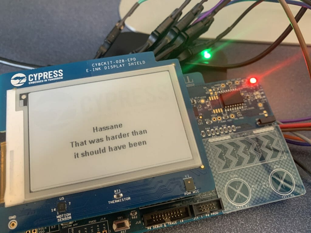
    There are a few things in the PSoC Creator example code which I didn’t really like, so, for the final solution, I would like it to be

    • In Modus Toolbox 1.1
    • Using FreeRTOS
    • Using the Segger emWin graphics library
    • Getting the best response time
    • Using DMA to drive the display

    For this article I will go through these steps:

    1. Build CE223727 EmWin_Eink_Display in PSoC Creator
    2. Explain the PSoC Creator Project
    3. Create a new MTB Project & add the FreeRTOS, Segger emWin and stdio middleware
    4. Configure the device for the correct pins, clocks and peripherals
    5. Setup FreeRTOS and Standard I/O
    6. Copy the driver files into the MTB project from the PSoC Creator workspace
    7. Port the drivers and eInkTask to work in MTB
    8. Program and Test
    9. (Part 2) Update the driver to remove the hardware timer
    10. (Part 2) Update the example to remove polled switch and use a semaphore
    11. (Part 2) Update the driver to use DMA
    12. (Part 2) Explain how the EINK EPD Display Works

    If you lack patience and you just want a working project, you can download it from the IoT Expert GitHub site. git@github.com:iotexpert/eink-emwin-mtb1-1.git

    First build CE223727 EmWin_Eink_Display in PSoC Creator

    Start by finding the code example project for the Eink Display.  In PSoC Creator on the File->Code Example menu you will be able to pick out the code example.
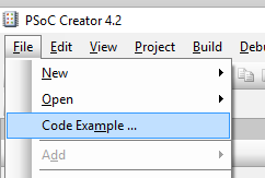
    There are a bunch of code examples, so the easiest way to find them is the filter based on “emwin”.  I did this because I knew we had used the Segger emWin Graphics library.  Notice in the picture below there are two emWin examples.  One with a “world” beside it and one without.  The world symbol means that it is on the internet and you will need to download it.  You can do that by clicking the world button.  Probably, you will find that your CE223727 EmWin_EInk_Display will have a world beside it and you will need to download it before you can make the project.
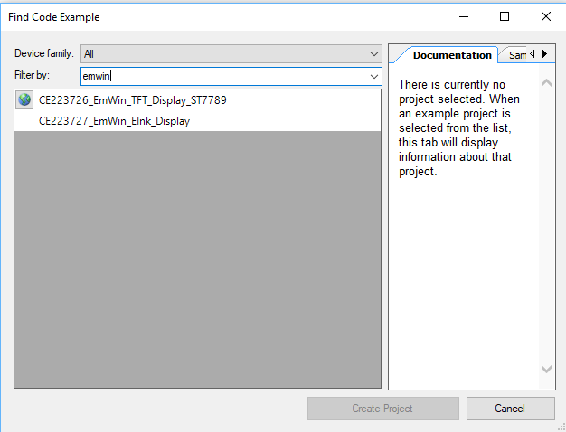
    Once you click create project it will ask you about the project.  Just click “next”
    Then give your project (and workspace) a name.  I called the workspace “EPDExample” and the project “CE22….”
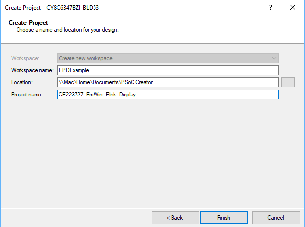
    After all of that is done you will have a schematic (and all of the other stuff required for the project).
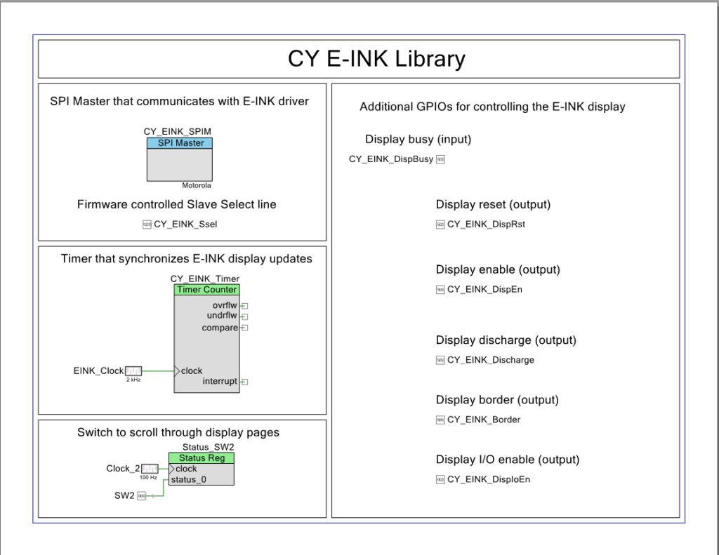
    When you click the program button it will ask you which MCU target to program (pick either, it doesnt matter)
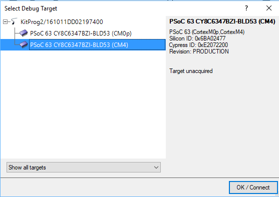
    After a while, your console window should look like this.

    And you development kit should do its thing.
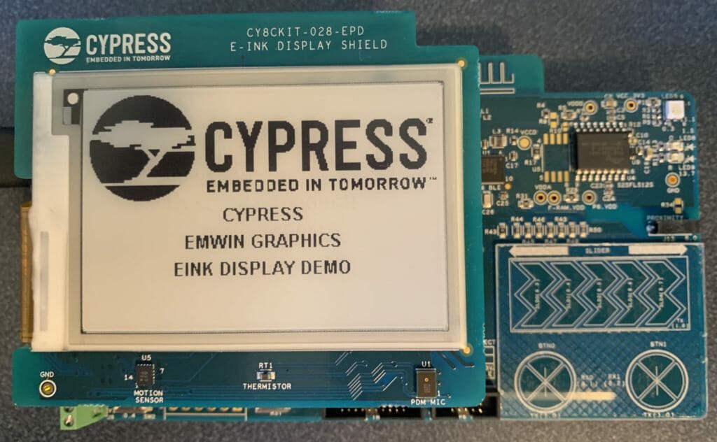
    Explain the PSoC Creator Project

    Now, lets have a look at the project.  Starting on the upper left hand part of the schematic you find that the interface to the EPD is via a SPI.  The SPI slave select is controlled with the Pervasive driver firmware rather than letting the SPI block directly control it.
    The SPI is configured to be 16 megabits per second with CPHA=0 and CPOL=0.
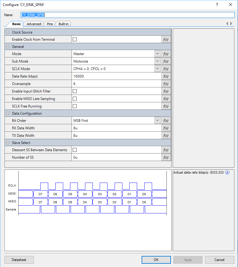
    I didn’t notice this at first, but in the picture above you can see that the actual speed of the SPI is 8.33 mbs.  That isn’t 16mbs for sure.  But why the gap?  The first thing to know is that in order for the SPI block to work correctly the input clock must be set at the desired datarate times the oversample.  What is oversample?  That is a scheme to get rid of glitchy-ness in the input signal.  In this case it will take 6 input samples to determine if the input is a 1 or a 0.  (median filter I think).  With this configuration the input clock to the SCB needs to be 16mbs * 6 = 96mhz.

    But what is the input clock frequency?  If you click on the dwr->clocks you will see this screen which shows that the input clock is 50Mhz (the last line highlighted in blue).  Further more you can see that the source clock for the SCB is “Clk_Peri”.  When you divide 50mhz source clock rate by 6 oversample you will find that the actual bitrate is 8.33kbs.
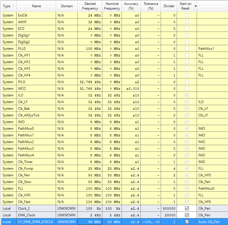
    But where does the 50mhz come from?  Well, the clock system is driven by the “IMO”.  IMO stands for internal main oscillator and it is a trimmed RC oscillator built into the chip. (thanks Tim).  This oscillator runs into an FLL which up converts it to 100MHz.
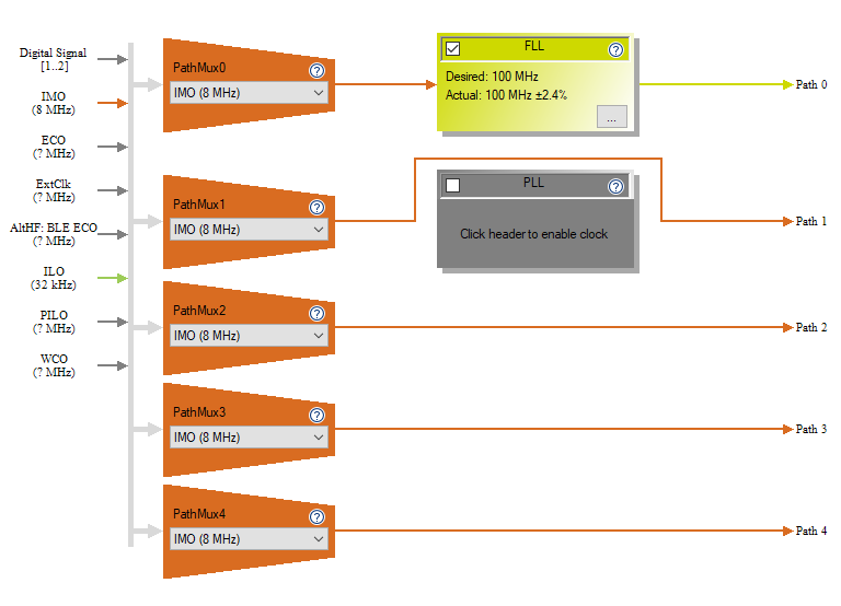
    That signal is then run into the “Clk_Peri” divider which divides it by two to yield a clock of 50MHz.  Which is not all that close to 96MHz… and means that our SPI runs at the wrong speed.
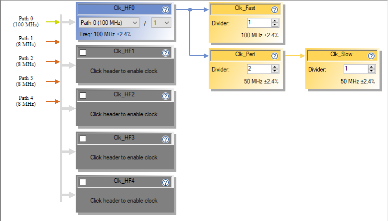
    But what does the EPD driver chip actually want?  You can find the documentation for this EPD on the Pervasive website.  That web page also has a link to the Product Specification 2.7″ TFT EPD Panel (E2271CS021) Rev.01 as well as the driver chip COG Driver Interface Timing for small size G2 V231

    When you look in the timing document you will find that the actual chip can take up to a 20Mhz input clock.  This means that our code example actually updates the screen at 42% (8.33/20) of what it could.  That gives us a chance to make things faster… which I will do after the port to MTB.

    The next sectin of the schematic has a TCPWM that is configured as a timer.  This has an input clock of 2kHz.
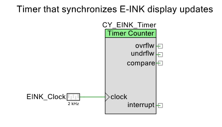
     

    And is setup to divide by 2 which will yield a counter that updates every 1ms.  The author of this code example used the TCPWM to time operations inside of the driver (which I will also replace with something better)
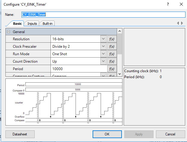
    Lastly there are some GPIOs that control various control pins on the display.  I don’t really know what all of the pins do, but will sort it out in the next article.
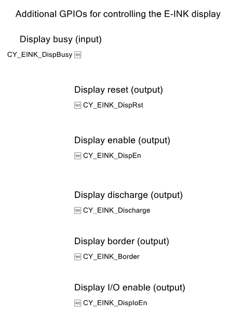
    And all of the pins are assigned like this:
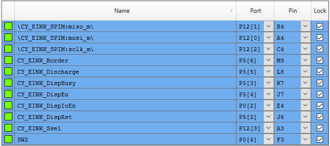
    Create a new MTB project & Add the Middleware

    It is time to start the project in MTB.  Start up Modus Toolbox 1.1 and select File->New->ModusToobox IDE Application    

    Then select the CY8CKIT-062-BLE Development Kit.  This kit comes with the CY8CKIT-028-EPD EINK Shield that you can see in the pictures above.
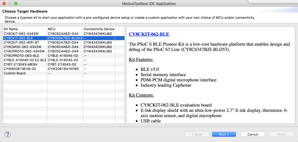
    I decide to call my project “EHKEink” and I derive my project from the “EmptyPSoC6App” template.
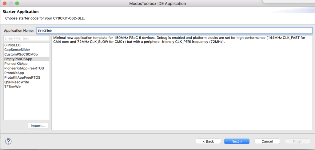
    Once that is done, Let it rip.
    And you should end up with a screen that looks like this. On the left in the workspace explorer you see the main app project.  In the middle you see the readme file which explains how this project is configured.
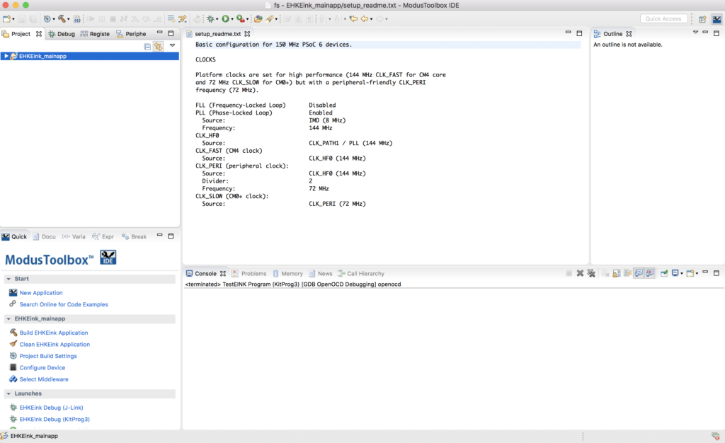
    The next step is to add the “Middleware” that we need to make this project work.  You can do this by clicking the select Middleware button from the ModusToolbox quick panel.
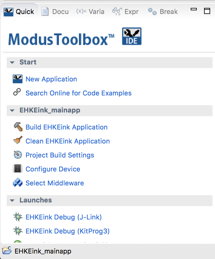
    For this project we need

    • FreeRTOS
    • Retarget I/O
    • Segger emWin Core, OS, no Touch, Soft FP
    • Segger emWin display driver BitPlains

    The middleware selector will bring in all of the drivers you selected into your project.  You can see that it also adds the FreeRTOS configuration file “FreeRTOSConfig.h” as well as “stdio_user.c” etc.  These files endup in the source folder and are for you to edit.
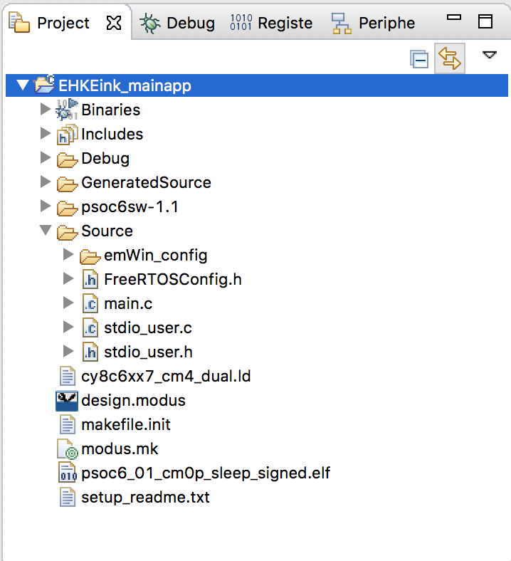
    While I was working on this, I found a bug in the emWin middleware, specifically the the configuration files for BitPlains get included twice.  To fix this you need to change the project properties and remove the path to “..components/psoc6mw/emWin/code/drivers/BitPlains/config”.  To do this, select the project in the workspace explorer then right click and select properties.
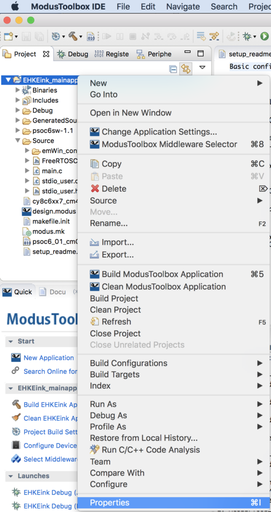
    Then select “C/C++ General –> Paths and Symbols”.  Select the “…BitPlains/config” path and click “Delete”
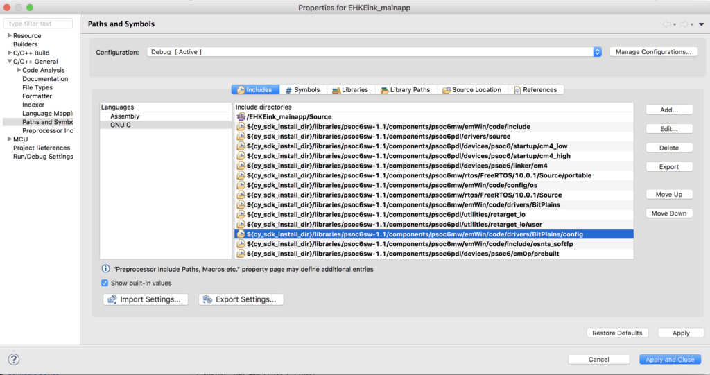
    Configure the device in MTB

    Modus Toolbox does not have a “schematic” or a “dwr” like PSoC Creator.  In order to achieve the same functionality we built the “Configurator”.  This tool will let you setup all of the peripherals in your project.  To run it select “Configure Device” in the MTB Quick Panel.
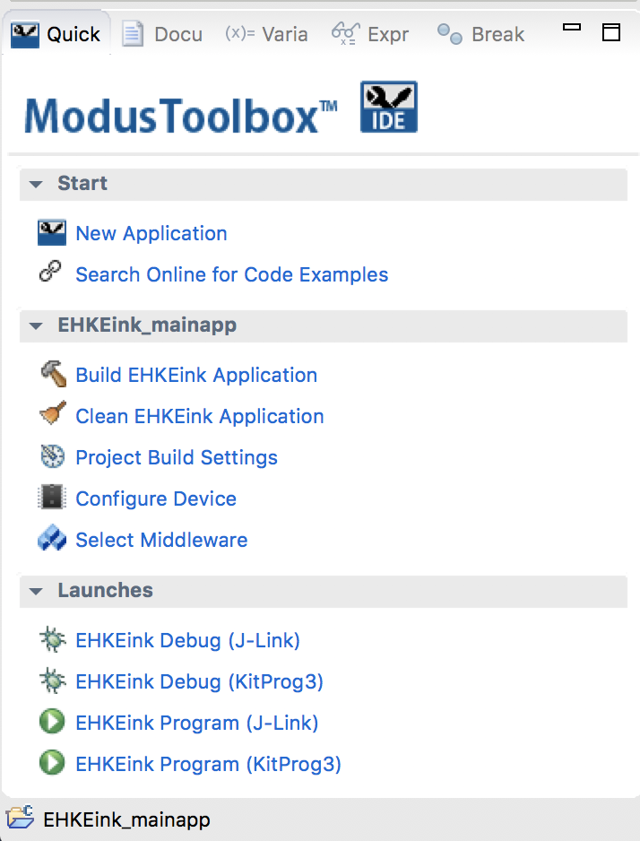
    Remember from the PSoC Creator Schematic we need to have:

    • A bunch of pins
    • A SPI
    • A Timer
    • Plus I want a UART to connect to standard I/O.

    First, click on the “Pins” tab.  This lets you set all of the configuration information for each of the pins on the chip.  I will go one by one enabling the pins and setting them as digital inputs or output.  I am going to give all of the pins that exact same names that they had in the PSoC Creator Project because I know the author of that project used PDL.  When you give a pin a name in the configurator it will generate #defines or c structures based on the name.  This will make the source code the original PSoC Creator author wrote almost exactly compatible with MTB.

    Here is an example of the first output pin which is P0[2] and is named CY_EINK_DispIoEn.  For the output pins you need to do four things.

    1. Enable the checkbox next to the pin name. (in this case P0[2])
    2. Give the pin a name (CY_EINK_DispIoEn)
    3. Set the drive mode (Strong Drive, Input buffer off)
    4. Set the initial state of the pin (High (1))
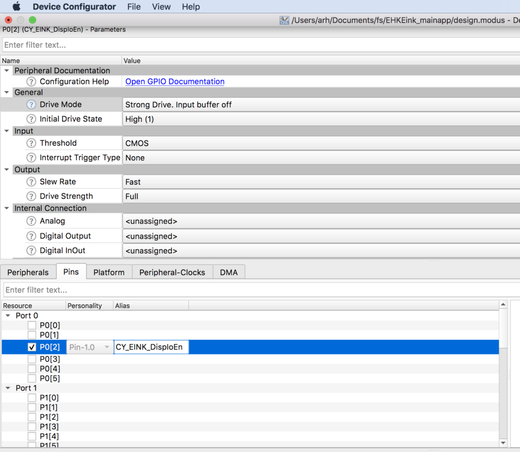
    Now, you need to go one by one turning on all of the output pins (Im not showing you screen shots of all of them)

    There are two input pins for this project SW2 P0[4] and CY_EINK_DispBusy P5[3].  For these pins I will:

    1. Enable the pin checkbox
    2. Give the pin a name (in this case SW2)
    3. Resistive Pull-Up, Input buffer on.  Note for P5[3] the pullup resistor is not needed
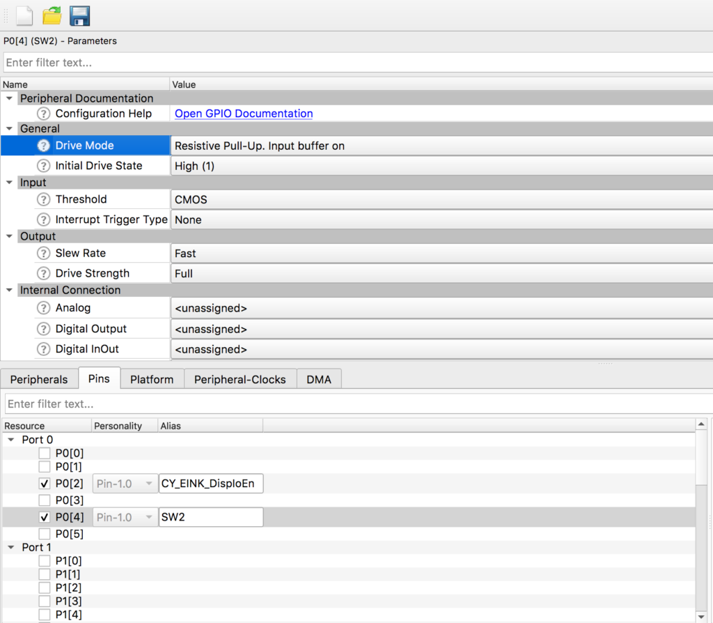
    Now that the digital pins are configured, you can setup the STDIO Uart.  This will be used to send debugging messages to the console Uart which is attached to your computer via a USB<->UART bridge in KitProg 3.

    Start by enabling SCB5 and giving it the name “UART”.  Make sure that the baud rate is set to 115200 and the rest to 8n1
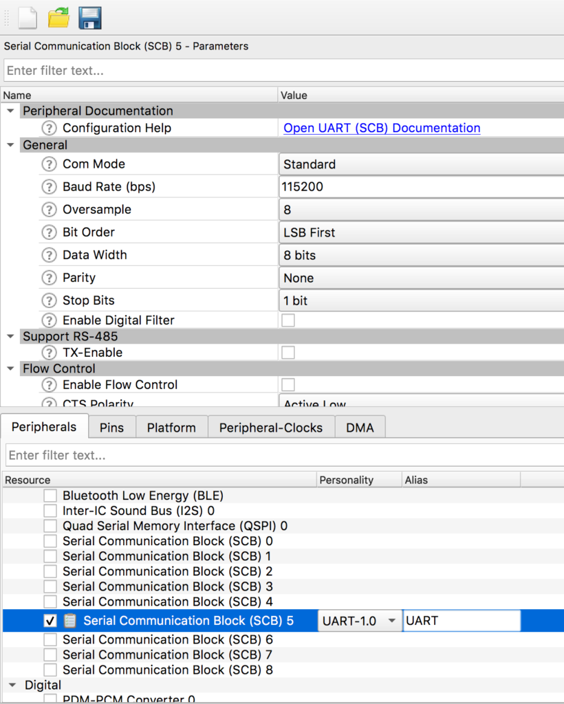
    Scroll down the window and pick out the RX and TX Pins plus the clock (any of the 8-bit clock dividers will do.  In this case I chose Divider 0)
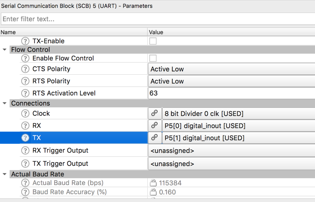
    Now, you need to setup the SPI.  To do this turn on SCB 6, set it to SPI, give it the name “CY_EINK_SPIM”, set it to “Master”, fix the data rate to 1000
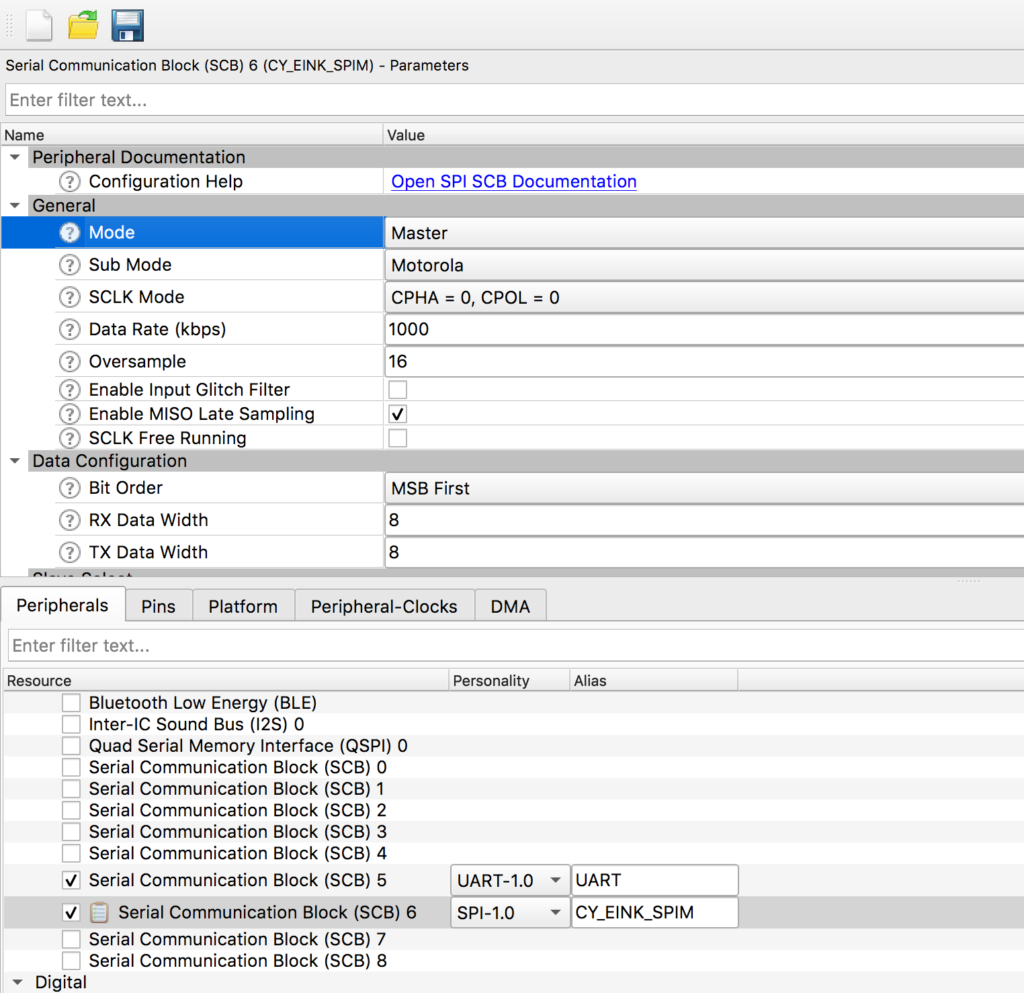
    Then scroll down to the “Connections” section and assign the pins
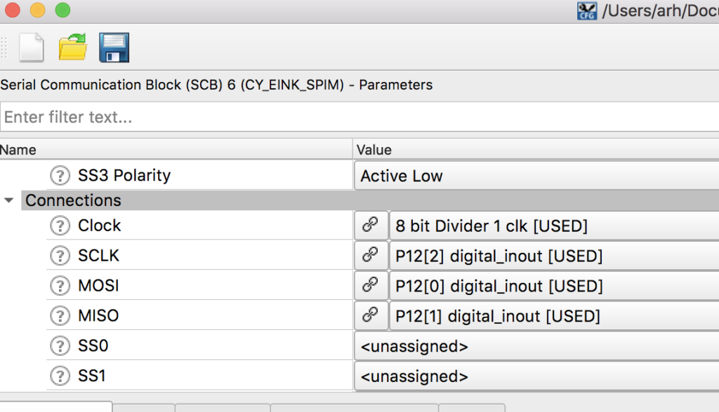
    The last bit of hardware we need is a timer with a 1000kHz input clock, in other words a millisecond timer.  To do this start by enabling TCPWM[1] 16-bit counter.  Call it “CY_EINK_Timer” which was the same name as the PSoC Creator project.  Then setup

    • As a “Timer Counter”.
    • One shot
    • Up count
    • Period is 65535 (aka the max)
    • And pick “Clock signal” as 16 bit Divider
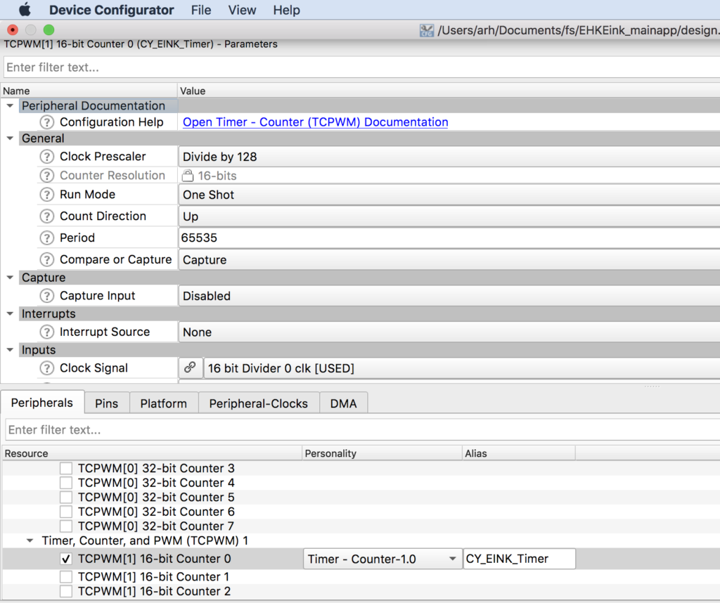
    Given that we want it to count milliseconds and the input has a 128 bit pre-divider… we need for the input clock to be setup to 128khz.  Click on “Peripheral clocks” then select “16 Bit Divider 0”.  Notice that the input frequency is 72Mhz and we need 128Khz… to get this a divider of 562 is required.  72mhz/128khz = 562
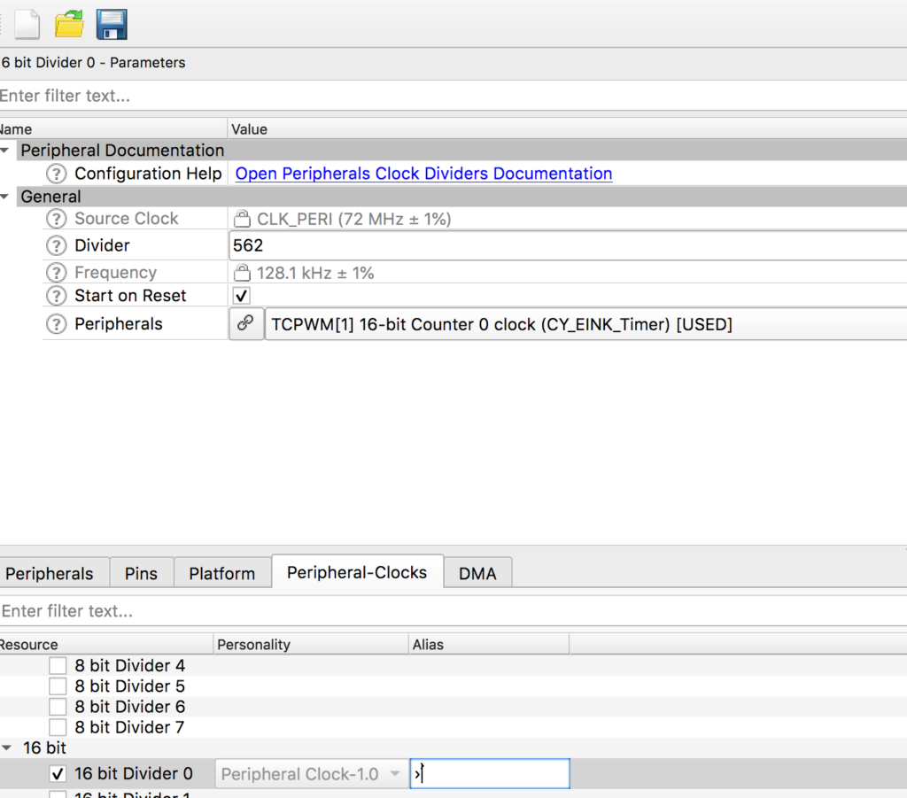
    Setup FreeRTOS and Standard I/O

    The next step is to setup the “plumbing”.  In this projet we are using FreeRTOS and Standard I/O. To configure FreeRTOS just edit the “FreeRTOSConfig.h” and remove the “warning”

    #warning This is a template. Modify it according to your project and remove this line. 
    

    Enable mutexes on line 57

    #define configUSE_MUTEXES                       1
    

    Make the heap bigger on line 70

    #define configTOTAL_HEAP_SIZE                   1024*48
    

    Change the memory scheme to 4 on line 194

    #define configHEAP_ALLOCATION_SCHEME                (HEAP_ALLOCATION_TYPE4)
    

    To enable the UART to be used for Standard I/O, edit “stdio_user.h” and add the includes for “cycfg.h”.  Then update the output and input Uart to be “UART_HW” (which is the name you gave it in the configurator)

    #include "cycfg.h"
    /* Must remain uncommented to use this utility */
    #define IO_STDOUT_ENABLE
    #define IO_STDIN_ENABLE
    #define IO_STDOUT_UART      UART_HW
    #define IO_STDIN_UART       UART_HW
    

    Now make a few edits to main.c to

    • Add includes for the configuration, rtos and standard i/o
    • Create a context for the UART
    • Create a blinking LED Task
    • In main start the UART and start the blinking LED task.
    #include "cy_device_headers.h"
    #include "cycfg.h"
    #include "FreeRTOS.h"
    #include "task.h"
    #include <stdio.h>
    
    cy_stc_scb_uart_context_t UART_context;
    
    void blinkTask(void *arg)
    {
    	(void)arg;
    
        for(;;)
        {
        		vTaskDelay(500);
        		Cy_GPIO_Inv(LED_RED_PORT,LED_RED_PIN);
        		printf("blink\n");
        }
    }
    int main(void)
    {
        init_cycfg_all();
        __enable_irq();
    
        Cy_SCB_UART_Init(UART_HW,&UART_config,&UART_context);
    	Cy_SCB_UART_Enable(UART_HW);
    
      	xTaskCreate( blinkTask,"blinkTask", configMINIMAL_STACK_SIZE,  0,  1, 0  );
      	vTaskStartScheduler();
      	while(1);// Will never get here
    }
    

    As I edited the code I notice that it can’t find “LED_RED” which made me realize that I forgot to add the LED_RED attached to P0[3] in the configuration.  So, I go back and update P0[3] to be LED_RED as strong drive digital output.

    Finally just to make sure that it is all working lets program the kit.  When I press “EHKEink Program” form the quickpanel…
    I get this message in the console.
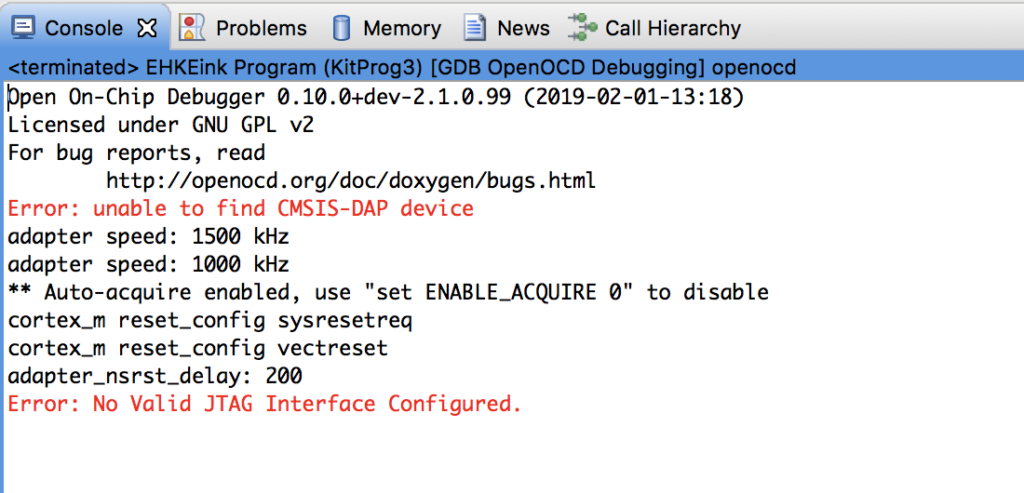
    But how can that be?  I have my kit plugged in?  In order to program your kit using Modus you need “KitProg3”.  PSoC Creator can program you kit with KitProg3 only if it is in the CMSIS-DAP HID mode.  To switch you development kit to KitProg3, you can use the program “fw-loader” which comes with MTB.  You can see what firmware you have by running “fw-loader –device-list”.  To change to KitProg 2 run “fw-loader –update-kp2” and to update to KitProg3 run “fw-loader –update-kp3”
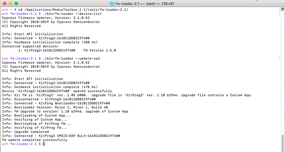
    Now when i program I get both the LED blinking and the console printing blink.
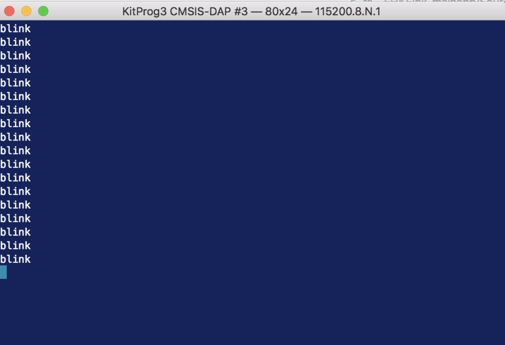
    Copy the files into the MTB project

    Next, I want to bring over the drivers from the PSoC Creator project.  They reside in folder called “eInk Library” inside of the PSoC Creator project.  You can copy them by navigating to the PSoC Creator workspace, then typing ctrl-c in the File Explorer, then clicking the “Source” directory in your Eclipse WorkSpace explorer and typing ctrl-v
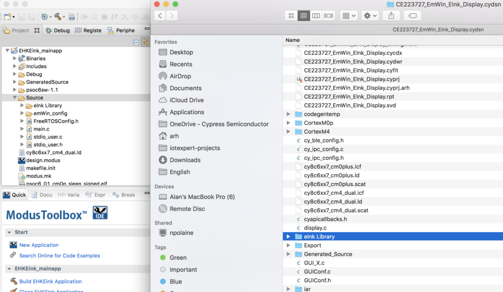
    You will also need the four files “GUIConf.c”, “GUIConf.h”, “LCDConf.h” and “LCDConf.c”.  Copy and paste them into the emWin_config directory.

    For this project I am going to use the code that existed in “main.c” from the original PSoC Creator project.  But I want it to be a task (and a few other changes).  To facilitate things, I will copy it as well. Then rename it to eInkTask.c.  And finally, the file “Cypress Logo Full Color_png1bpp.c” needs to be copied as well.

    After all of those copies you should have your project looking something like this:
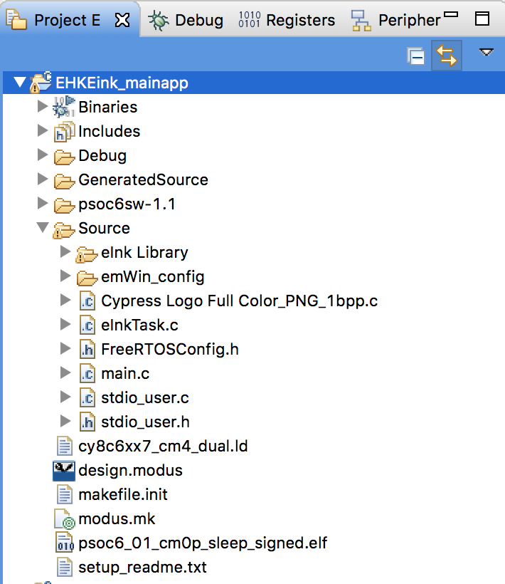
    Port the Drivers and eInkTask

    Now we need to fix all of the driver code.  Big picture you will need to take the following actions.

    • Update the Project settings to include the new folders (emWin_config and emWin Library)
    • Replace the PSoC Creator #include <project.h> with MTB #include “cycfg.h”
    • Update the files to have #include “FreeRTOS.h” and “task.h” where appropriate
    • Replace all of the CyDelay’s with vTaskDelays
    • Fix the old PSoC Creator component calls for the timer with PDL calls

    First go to the project settings (remember, click on the project then select properties).  Then pick “C/C++ Build Settings” then “GNU ARM Cross C Compiler” and “includes”  Press the little green “+” to add the new directories
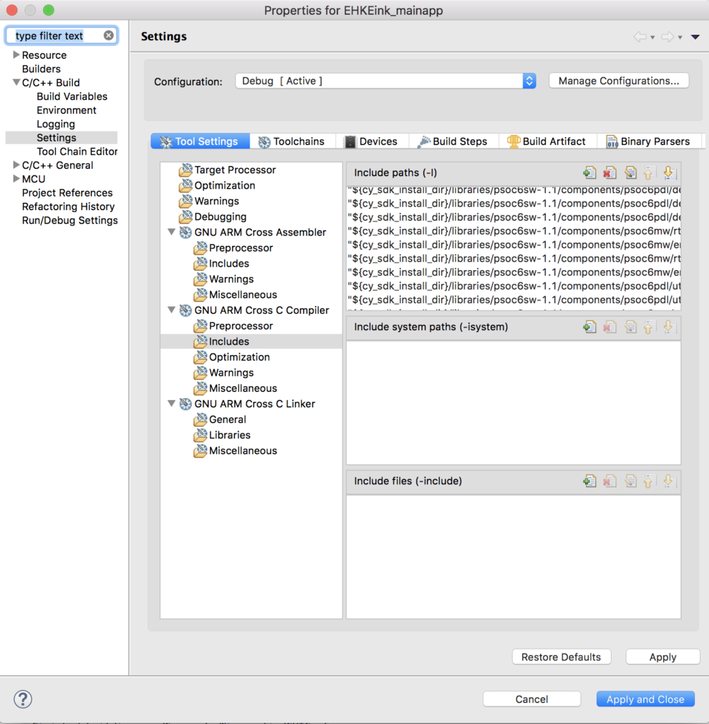
    You can select both directories at once.
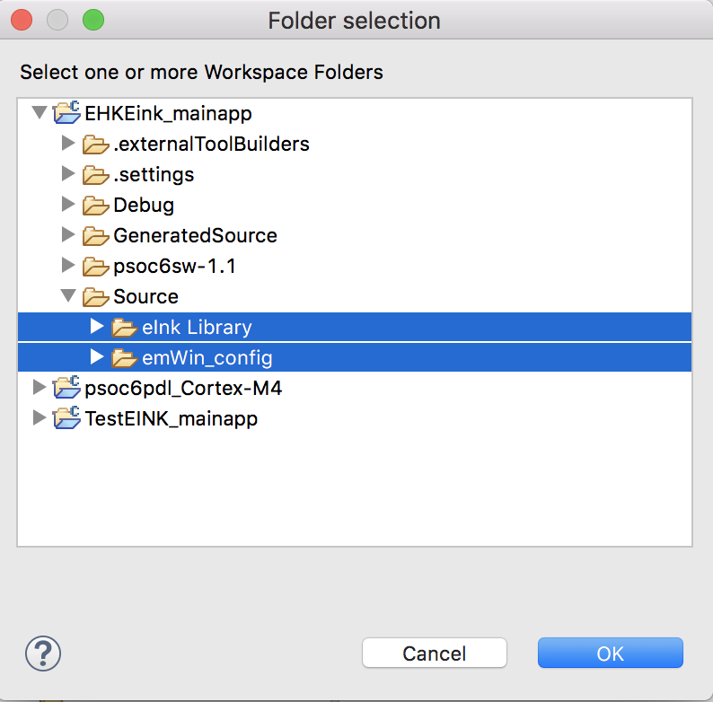
    Next edit  eInkTask.c

    Update #include “project.h” to be #include “cycfg.h” on line 59.  Add “FreeRTOS.h” and “task.h” to the includes.

    #include "cycfg.h"
    #include "GUI.h"
    #include "pervasive_eink_hardware_driver.h"
    #include "cy_eink_library.h"
    #include "LCDConf.h"
    #include "FreeRTOS.h"
    #include "task.h"
    #include <stdio.h>

    Find and replace “CyDelay” with “vTaskDelay”

    Update the PSoC Creator component call  _Read with the pdl calls Cy_GPIO_Read on line 661

    void WaitforSwitchPressAndRelease(void)
    {
        /* Wait for SW2 to be pressed */
        while(Cy_GPIO_Read(SW2_PORT,SW2_PIN) != 0);
        
        /* Wait for SW2 to be released */
        while(Cy_GPIO_Read(SW2_PORT,SW2_PIN) == 0);
    }

    Update the “int main(void)” to be “void eInkTask(void *arg)” on line 687

    void eInkTask(void *arg)
    {
    	(void)arg;

    Remove ” __enable_irq(); /* Enable global interrupts. */” from the old main on line 695.

    In the file cy_eink_psoc_interface.h

    Update the #include <project.h> to be #include “cycfg.h” on line 59.

    In the file cy_eink_psoc_interface.c

    Create a context for the SPIM by adding on line 58:

    cy_stc_scb_spi_context_t CY_EINK_SPIM_context;
    

    The three timer functions in this file use the old PSoC Creator component timer interface APIs rather than the PDL interface.  So you will need to change Cy_EINK_TimerInit, Cy_EINK_GetTimeTick and Cy_EINK_TimerStop to use PDL.

    Here is Cy_EINK_TimerInit

    void Cy_EINK_TimerInit(void)
    {   
        /* Clear the counter value and the counter variable */
        //CY_EINK_Timer_SetCounter(0);
    
        Cy_TCPWM_Counter_Init (CY_EINK_Timer_HW, CY_EINK_Timer_NUM, &CY_EINK_Timer_config);
        Cy_TCPWM_Counter_SetCounter	(	CY_EINK_Timer_HW, CY_EINK_Timer_NUM,0);
        
        Cy_TCPWM_Enable_Multiple(	CY_EINK_Timer_HW,CY_EINK_Timer_MASK);
        /* Initialize the Timer */
        //CY_EINK_Timer_Start();
        Cy_TCPWM_TriggerStart	(	CY_EINK_Timer_HW,CY_EINK_Timer_MASK);
    }
    

    And Cy_EINK_GetTimeTick

    uint32_t Cy_EINK_GetTimeTick(void)
    {
        /* Variable used to store the time tick */
        uint32_t timingCount;
        
        /* Read the current time tick from the E-INK Timer */
        //timingCount = CY_EINK_Timer_GetCounter();
        timingCount = Cy_TCPWM_Counter_GetCounter	(CY_EINK_Timer_HW, CY_EINK_Timer_NUM);
    
    
        /* Return the current value of time tick */
        return(timingCount);
    }

    And Cy_EINK_TimerStop

    void Cy_EINK_TimerStop(void)
    {
        /* Stop the E-INK Timer */
        //CY_EINK_Timer_Disable();
    	Cy_TCPWM_Counter_Disable(CY_EINK_Timer_HW, CY_EINK_Timer_NUM);
    
    }

    In  the file LCDConf.h change the include to stdint.h and make the type uint8_t instead of uint8

    #include  <stdint.h>
        
    void LCD_CopyDisplayBuffer(uint8_t * destination, int count);

    In the file LCDConf.c remove the #include “syslib/cy_syslib.h” (I have no idea why it is/was there) and then add “#include <stdint.h>”  On line 219 change “uint8” to be “uint8_t”

    void LCD_CopyDisplayBuffer(uint8_t * destination, int count)
    

    In the file cy_eink_fonts.h change the “#include <project.h>” to be

    #include <stdint.h>
    #include <stdbool.h>

    In main.c add an external reference to the eInkTask on line 36 (yes this is really ugly Alan)

    extern void eInkTask(void *);
    

    And start the eInkTask on line 58.  Notice that I put in 10K for the stacksize… but I dont actually know how much it takes.

      	xTaskCreate( eInkTask,"eInkTask", 1024*10,  0,  1, 0  );
    

    Program & Test the MTB Project

    When you program the development kit you should have

    1. A blinking RED LED
    2. The ability to scroll through a bunch of screens using the SW2 button.

    Here is a picture
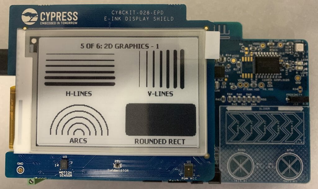
    In the next article I will:

    1. Speed up the SPI
    2. Get rid of the hardware timer
    3. Explain more about the EINK.
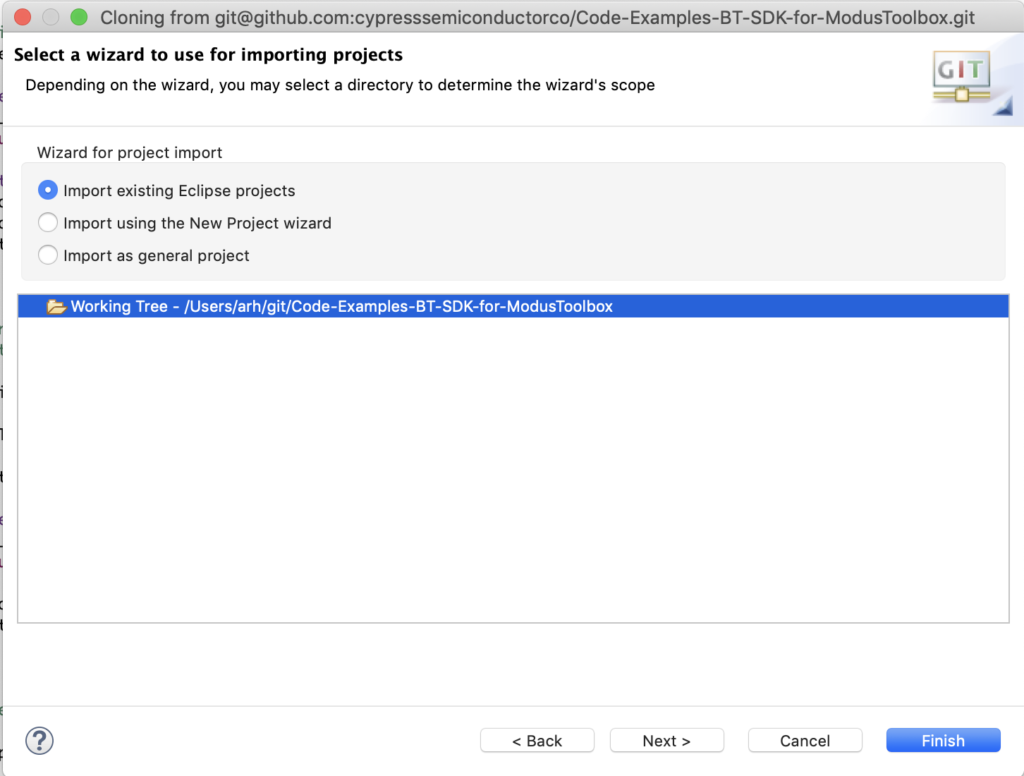
     

    MBEDOS Little File System & CY8CPROTO_62_4343W

    Summary

    This is the first article in a series that will discuss how to use the MBED OS file systems with Cypress SPI Nor Flash chips and PSoC 6.

    Title
    The Back Story & Making the LittleFS Work with the CY8CKIT_062_4343W
    The Architecture of Filesystems in MBEDOS
    SPI Nor Flash
    SFDP
    The MBED OS Quad SPI Driver
    LittleFS
    FATFS
    MBED OS and POSIX Files


    The Back Story

    On a bunch of our development kits there is a SPI NOR Flash sitting right next to the PSoC 6.  Which exact SPI flash depends on the exact generation of development kit.  I have always wanted to use these chips, but had never had time to sort out how they work.  And quite frankly we never made it very easy to use them because although they were connected, we didn’t provide much in the way of software support.  However, with the advent of MBED OS at Cypress we were suddenly gifted with two file systems to use, LittleFS and FATFS.

    This journey starts with an email note to the Applications manager in India (an awesome woman named Jaya)… “Hey, can you get someone to send me an example of the MBED OS flash file system on the CY8CPROTO_062_4343W.”  A day or so later I got an email with an attached project and a “memo” that explained what to do.  This exchange happened right before Embedded World in February and I was really busy.  Finally, a couple of weeks ago I read the email and the instructions which started with “Break off the NOR Flash wing and solder….”  If you look in the picture below you can see that at the top of the kit there is a breakaway wing (circled in green) that has a SPI Flash chip on it (circled in red).

    Honestly, I didn’t read any further than “.. break off the wing…”.  So, I sent another note … “Uh… how about no.  Why can’t I use the development kit without soldering?”… And these two emails were my first steps down the Embedded FileSystem & NOR Flash Rabbit Hole which is the subject of this series of articles.

    Making the LittleFS Work with the CY8CKIT_062_4343W

    I am going to start by giving you the step by step instructions to make the LittleFS work … and these instruction will only include a little bit of commentary on how it works.  I will expand on the “how” in all of the follow on articles.  To make it work you need to follow these steps:

    1. Clone the MBEDOS FileSystem Example
    2. Clone my QSPI driver path
    3. Then patch MBEDOS with the updated QSPI driver.
    4. Test
    5. Examine the Project

    The first step in the process of running the example is to clone the MBED OS Example Project for Filesystems.  To do this, run “mbed import mbed-os-example-filesystem”.  As I noted above, the default MBED does not have the required drivers for the Quad SPI interface.  Fortunately another excellent Applications engineer in India named Vaira built me a QSPI driver in advance of the actual official release from Cypress.  I have put these drivers on the iotexpert github repository and you can get them with a “git clone git@github.com:iotexpert/MBED_QSPI_PATCHES.git”.  Once you have them you can apply the patch by

    1. cd mbed-os-example-filesystem
    2. ../MBED_QSPI_PATCHES/patch-qspi-mbed.sh

    The shell script is simple program that copies the driver files into the correct locations in your mbed-os directory in your current project.  I will talk in detail about these files in a later article.

    #!/bin/sh
    
    cp ../MBED_QSPI_PATCHES/qspi_api.c ../MBED_QSPI_PATCHES/objects.h mbed-os/targets/TARGET_Cypress/TARGET_PSoC6
    cp ../MBED_QSPI_PATCHES/targets.json mbed-os/targets
    cp ../MBED_QSPI_PATCHES/PinNames.h mbed-os/targets/TARGET_Cypress/TARGET_PSOC6/TARGET_CY8CMOD_062_4343W/TARGET_CY8CPROTO_062_4343W/

    Here is what my terminal looks like after I run the import, clone and apply patches.

    Next I will build the project “as-is” using “mbed compile -t GCC_ARM -m CY8CPROTO_062_4343W”

    OK, the project looks like it builds with no problems (other than a very annoying boatload of warnings – I really wish people weren’t slobs).  Running the compile also has the nice side effect of setting the default target and toolchain.  You can see this by either looking at the “.mbed” file or by running “mbed config target” or “mbed config toolchain”.  Here is what my terminal window looks like

    Test

    I generally like to test a project before I start making changes to it.  I already compiled, so now, I program it into the board with either the Cypress Programmer or by running “mbed compile -f”.  When you attach a serial program to the development kit you will get something like this:

    So, the project seems to work.  When I run the project again (by pressing the reset button on the board), here is what I get:

    But what is it doing?  First, lets get the code into an editor where we can see what is happening:

    Visual Studio Code

    Recently, I have been using Visual Studio Code to view and edit my projects.  To make that experience better, it is a good idea to “export” the project from the MBED CLI.  This doesn’t change anything in your project, but it does create the files to make VSCODE work better.  To do this run “mbed export -i vscode_gcc_arm -m CY8CPROTO_062_4343W –profile mbed-os/tools/profiles/debug.json”

    When you start VSCODE it will look something like this:

    When I open the directory with my project with the “File -> Open …” menu

    It will look like this:

    Examine the Project

    Now click on main.cpp and your screen should look like this:

    To make any of the MBED OS Filesystems work, they need to have a “BlockDevice” to read and write the media, meaning the SPI Flash or SD Card or … The project as it comes from ARM creates the BlockDevice on line 23 where it asks for the “default_instance”.  Those configuration files which we patched MBED with earlier sets up the default instance to be the QSPI flash on the development kit (which I will explain in great detail in a later article).

    After you have a BlockDevice, the next thing that you need is a FileSystem object.  In this case on line 31-33 you can see that this project uses a LittleFileSystem.  The argument to the LittleFileSystem object creation is the mount point (think Unix “/fs/”).  The mount point is used by all of the POSIX APIs (open, close, read etc).  I will talk more about POSIX in later article.

    // This example uses LittleFileSystem as the default file system
    #include "LittleFileSystem.h"
    LittleFileSystem fs("fs");

    Near the start of main, the first real thing that happens is that you need to “mount” the Filesystem onto the BlockDevice.  This is done on line 80.  The mount will return an non-zero error code if there is nothing on the SPI Flash or the SPI Flash is corrupted.  If the mount fails, the program will try to create a filesystem by calling “reformat” on line 87.  If that fails the “error” will halt the whole thing and blink the red light on the board.

        int err = fs.mount(bd);
        printf("%s\n", (err ? "Fail :(" : "OK"));
        if (err) {
            // Reformat if we can't mount the filesystem
            // this should only happen on the first boot
            printf("No filesystem found, formatting... ");
            fflush(stdout);
            err = fs.reformat(bd);
            printf("%s\n", (err ? "Fail :(" : "OK"));
            if (err) {
                error("error: %s (%d)\n", strerror(-err), err);
            }
        }

    Once we have a Filesystem (object) and it is formatted, the project will try to open the file “/fs/numbers.txt” using the POSIX API “open” on line 97.  The open specifics that it is to open the file for “read” and that it will append the “+”.  If that operation fails, it will try to create the file on line 103.

     FILE *f = fopen("/fs/numbers.txt", "r+");
        printf("%s\n", (!f ? "Fail :(" : "OK"));
        if (!f) {
            // Create the numbers file if it doesn't exist
            printf("No file found, creating a new file... ");
            fflush(stdout);
            f = fopen("/fs/numbers.txt", "w+");
            printf("%s\n", (!f ? "Fail :(" : "OK"));
            if (!f) {
                error("error: %s (%d)\n", strerror(errno), -errno);
            }

    If the file was opened for the first time, it will write the numbers 0-9 into the file using the loop (109) and fprintf (line 112).  The file will have lines with 4 spaces followed by a number then a “\n”.  This format was chosen to make the parsing easier later on in the program.

            for (int i = 0; i < 10; i++) {
                printf("\rWriting numbers (%d/%d)... ", i, 10);
                fflush(stdout);
                err = fprintf(f, "    %d\n", i);
                if (err < 0) {
                    printf("Fail :(\n");
                    error("error: %s (%d)\n", strerror(errno), -errno);
                }
            }
            printf("\rWriting numbers (%d/%d)... OK\n", 10, 10);

    Once the file is initialized, you want the put the file point back to the start which is done with the “fseek” on line 122.

            printf("Seeking file... ");
            fflush(stdout);
            err = fseek(f, 0, SEEK_SET);
            printf("%s\n", (err < 0 ? "Fail :(" : "OK"));
            if (err < 0) {
                error("error: %s (%d)\n", strerror(errno), -errno);
            }

    The main part of the program will start at the top,  read the numbers and increment them, and write them back into the file.  I am not really in love with this block of code… but I suppose that it is functional.

        // Go through and increment the numbers
        for (int i = 0; i < 10; i++) {
            printf("\rIncrementing numbers (%d/%d)... ", i, 10);
            fflush(stdout);
    
            // Get current stream position
            long pos = ftell(f);
    
            // Parse out the number and increment
            int32_t number;
            fscanf(f, "%d", &number);
            number += 1;
    
            // Seek to beginning of number
            fseek(f, pos, SEEK_SET);
        
            // Store number
            fprintf(f, "    %d\n", number);
    
            // Flush between write and read on same file
            fflush(f);
        }
        printf("\rIncrementing numbers (%d/%d)... OK\n", 10, 10);

    Once all of the numbers are incremented and written back into the file, the last step is closing the file on line 156.

        // Close the file which also flushes any cached writes
        printf("Closing \"/fs/numbers.txt\"... ");
        fflush(stdout);
        err = fclose(f);
        printf("%s\n", (err < 0 ? "Fail :(" : "OK"));
        if (err < 0) {
            error("error: %s (%d)\n", strerror(errno), -errno);
        }

    The next phase of the program is to do a directory listing using the POSIX directory APIs (opendir, readdir,closedir).  This little block of code will print out all of the files in the “/fs” directory.

      // Display the root directory
        printf("Opening the root directory... ");
        fflush(stdout);
        DIR *d = opendir("/fs/");
        printf("%s\n", (!d ? "Fail :(" : "OK"));
        if (!d) {
            error("error: %s (%d)\n", strerror(errno), -errno);
        }
    
        printf("root directory:\n");
        while (true) {
            struct dirent *e = readdir(d);
            if (!e) {
                break;
            }
    
            printf("    %s\n", e->d_name);
        }
    
        printf("Closing the root directory... ");
        fflush(stdout);
        err = closedir(d);
        printf("%s\n", (err < 0 ? "Fail :(" : "OK"));
        if (err < 0) {
            error("error: %s (%d)\n", strerror(errno), -errno);
        }
    

    Then they demonstrate opening the numbers.txt file and printing out the data.

        // Display the numbers file
        printf("Opening \"/fs/numbers.txt\"... ");
        fflush(stdout);
        f = fopen("/fs/numbers.txt", "r");
        printf("%s\n", (!f ? "Fail :(" : "OK"));
        if (!f) {
            error("error: %s (%d)\n", strerror(errno), -errno);
        }
    
        printf("numbers:\n");
        while (!feof(f)) {
            int c = fgetc(f);
            printf("%c", c);
        }
    
        printf("\rClosing \"/fs/numbers.txt\"... ");
        fflush(stdout);
        err = fclose(f);
        printf("%s\n", (err < 0 ? "Fail :(" : "OK"));
        if (err < 0) {
            error("error: %s (%d)\n", strerror(errno), -errno);
        }

    And finally closing things up by unmounting the filesystem.

       // Tidy up
        printf("Unmounting... ");
        fflush(stdout);
        err = fs.unmount();
        printf("%s\n", (err < 0 ? "Fail :(" : "OK"));
        if (err < 0) {
            error("error: %s (%d)\n", strerror(-err), err);
        }
            
        printf("Mbed OS filesystem example done!\n");

    Super Annoying Hard Code

    All through this example program the number “10” is hardcoded.  This is called a MAGIC NUMBER and in this particular case is not at all a good thing.  Moreover, lines of code like this represent absolute insanity.

        printf("\rIncrementing numbers (%d/%d)... OK\n", 10, 10);
    

    Really… just don’t do this.  Friends don’t let friends use magic numbers.

    Erasing the FileSystem

    Near the top of main you can see that they register an interrupt to create an event when the button on the development kit is pressed.

       irq.fall(mbed_event_queue()->event(erase));

    The erase function simply initializes the block device, calls erase and then de-inits the block device.  This will cause the whole thing to begin anew when the kit is reset.

    void erase() {
        printf("Initializing the block device... ");
        fflush(stdout);
        int err = bd->init();
        printf("%s\n", (err ? "Fail :(" : "OK"));
        if (err) {
            error("error: %s (%d)\n", strerror(-err), err);
        }
    
        printf("Erasing the block device... ");
        fflush(stdout);
        err = bd->erase(0, bd->size());
        printf("%s\n", (err ? "Fail :(" : "OK"));
        if (err) {
            error("error: %s (%d)\n", strerror(-err), err);
        }
    
        printf("Deinitializing the block device... ");
        fflush(stdout);
        err = bd->deinit();
        printf("%s\n", (err ? "Fail :(" : "OK"));
        if (err) {
            error("error: %s (%d)\n", strerror(-err), err);
        }
    }
    

    The first time I ran the erase, I thought that there was something wrong… and I ended up going through a big debug loop.  The final step in the debug loop was being patient… which isn’t really in my wheelhouse.  I added this little block of code which timed the erase operation.

        Timer t;
        t.start();
        err = bd->erase(0,bd->size());
        t.stop();
        
        printf("%s\n", (err ? "Fail :(" : "OK"));
        if (err) {
            error("error: %s (%d)\n", strerror(-err), err);
        }
        printf("Time in s =%f\n",((double)t.read_ms())/1000.0);

    And it turns out the answer is 115.06 seconds.  I am going to have to figure out why it takes so long.

    The last thing to notice is that if you press the erase button while it is writing the files, Im pretty sure that something bad happens.

    In the next articles I will examine this system in much much more detail.  Again thanks to Jaya and Vaira for their excellent work.


    MBED OS & PSoC 6 & SSD1306

    Summary

    As I wrote about in the last article I have been working to get ready for Embedded World 2019 in a week and a bit.  For my demo, I will be handing out remote controls that have a 128×64 monochrome OLED display that is driven by an I2C SSD1306.  This whole board is controlled by a PSoC 6 & a 4343W WiFi / Bluetooth Combo.

    This morning I started to port the U8G2 library to MBEDOS… but ran into some problems, so I i decided to see what ports were already out there.  I immediately found a port of the Adafruit_GFX library.  This article talks about using it on my CY8CPROTO_062_4343W board.  As part of this journey I also wanted to be able to draw the Cypress logo on the screen… so I had to figure out how to create a logo in a format that could be drawn on the screen.

    I will follow these steps:

    1. Create a new project & add the Adafruit_GFX_library
    2. Create a main.cpp, configure the library and test
    3. Make a Cypress logo using GIMP
    4. Create a function to draw X11 bitmaps & test

    Create a new project & add the Adafruit_GFX_library

    The first step to get everything going by running

    1. mbed new .
    2. mbed add http://os.mbed.com/users/nkhorman/code/Adafruit_GFX/

    The way to figure out how to add the library is by going to the library webpage on the mbedos website.  Then clicking the arrow on “Import into Compiler” where you will see two options, “Import into Compiler” and “Import with mbed CLI”

    When you select that option you will get a window that tells you the exact command to run.

    I have been using Atom as an editor (and sort of IDE).  When you open the lcd-example directory using Atom you will see your project including

    1. The mbed-os directory with all of the mbed stuff in it.
    2. The Adafruit_GFX library

    Create a main.cpp, configure the library and test

    The next step is to create a main.cpp.

    1. Setup the I2C.  In order to use the graphics library you need to setup a communication vehicle.  In my case that is an I2C bus that is connected to P6[0] and P6[1] on my development board.  Lines 6-15 create the communication class of I2CPreInit, configure it to 400kbs and connect the I2C master to P6[0]/P6[1]
    2. Line 16 actually setups up the graphics library and get it going.
    3. The main simply prints out some information about the display on lines 22-23
    4. Line 24 causes the current frame buffer to be displayed (more on this in a second)
    5. The main loop blinks the LED and prints a counter on the top of the screen.
    #include "mbed.h"
    #include "Adafruit_SSD1306.h"
    
    DigitalOut myled(LED1);
    
    class I2CPreInit : public I2C
    {
    public:
        I2CPreInit(PinName sda, PinName scl) : I2C(sda, scl)
        {
            frequency(400000);
            start();
        };
    };
    I2CPreInit gI2C(P6_1,P6_0);
    Adafruit_SSD1306_I2c gOled2(gI2C,P0_2,0x78,64,128);
    
    int main()
    {   uint16_t x=0;
    
        printf("Started\n");
        printf("%ux%u OLED Display\r\n", gOled2.width(), gOled2.height());
        printf("Rotation = %u\n",gOled2.getRotation());
        gOled2.display();
        while(1)
        {
            x += 1;
            myled = !myled;
            gOled2.printf("%u\r",x);
            gOled2.display();
            wait(1.0);
        }
    }
    

    In order to build this thing I run “mbed compile -t GCC_ARM -m CY8CPROTO_062_4343w”.  When I run the project it looks like this:

    There are several things to notice about this picture.  First, there is an Adafruit logo on the screen.  Where did this come from?  Simple on line 152 of Adafruit_ssd1306.cpp there is a function called “splash” which is called by the constructor.  The spash function just copies a bitmap into the frame buffer of the Adafruit_SSD1306 object.

    void Adafruit_SSD1306::splash(void)
    {
    #ifndef NO_SPLASH_ADAFRUIT
    	uint8_t adaFruitLogo[64 * 128 / 8] =
    	{ 
    		0x00, 0x00, 0x00, 0x00, 0x00, 0x00, 0x00, 0x00, 0x00, 0x00, 0x00, 0x00, 0x00, 0x00, 0x00, 0x00,
    

    The constructor is in Adafruit_ssd1306.h on line 152

    	Adafruit_SSD1306_I2c(I2C &i2c, PinName RST, uint8_t i2cAddress = SSD_I2C_ADDRESS, uint8_t rawHeight = 32, uint8_t rawWidth = 128)
    	    : Adafruit_SSD1306(RST, rawHeight, rawWidth)
    	    , mi2c(i2c)
    	    , mi2cAddress(i2cAddress)
    	    {
    		    begin();
    		    splash();
    		    display();
    	    };

    And if you don’t want to have this splash screen you can uncomment the #define NO_SPLASH_ADAFRUIT in the file “Adafruit_GFC_Config.h”

    #ifndef _ADAFRUIT_GFX_CONFIG_H_
    #define _ADAFRUIT_GFX_CONFIG_H_
    
    // Uncomment this to turn off the builtin splash
    #define NO_SPLASH_ADAFRUIT
    
    // Uncomment this to enable all functionality
    //#define GFX_WANT_ABSTRACTS
    
    // Uncomment this to enable only runtime font scaling, without all the rest of the Abstracts
    //#define GFX_SIZEABLE_TEXT
    
    
    #endif

    The next thing to notice in the picture is that I have lead wires attached to the LCD pins… and those wires are attached to a logic analyzer because I typed the I2C incorrectly and I couldn’t figure out why they didn’t talk.  And finally notice my grandfathers magnifying glass which I use every day.

    Make a Cypress logo using GIMP

    For my project I am less interested in displaying Adafruits Logo and more interested in displaying Cypress’.  To do this I loaded up the Cypress logo in Gimp.

    I then converted it to pure black and white using the “Image->Mode->Indexed…”

    Then selected “black and white palette”

    Then I scaled the image to 128×40 using the “Image->Scale Image”

    Unfortunately it made a bit of a mess of the logo during the scaling process… so I put my son to editing it.

    Which looks like this after he was done.  Pretty good eh?

    In order to use the image you need a “C program” version of it.  It turns out that there is a format called “X11” or “xbm” which is exactly that (a c-file).  You can read about the format on this website.  To get one of these files, just run “File->Export As”

    Then give it a name with a “.xbm” on the end

    Make sure and “de-select the X10 format bitmap” (and older version of the xbm format)

    When all that is said and done you will find the xbm file with goodness in it.  Here is the top of it.

    #define cylogo_width 128
    #define cylogo_height 40
    static unsigned char cylogo_bits[] = {
       0x00, 0x00, 0xff, 0x01, 0x00, 0x00, 0x00, 0x00, 0x00, 0x00, 0x00, 0x00,
       0x00, 0x00, 0x00, 0x00, 0x00, 0xe0, 0xff, 0x0f, 0x00, 0x00, 0x00, 0x00,
       0x00, 0x00, 0x00, 0x00, 0x00, 0x00, 0x00, 0x00, 0x00, 0xf8, 0xff, 0x3f,
       0x00, 0x00, 0x00, 0x00, 0x00, 0x00, 0x00, 0x00, 0x00, 0x00, 0x00, 0x00,
       0x00, 0xfe, 0xff, 0xff, 0x00, 0x00, 0x00, 0x00, 0x00, 0x00, 0x00, 0x00,
    

    The format of this file is unsigned 8-bit integers… each bit represents the bit of one pixel… in BIG ENDIAN!!!! format.  In other words this table will be 128×40/8 bytes long.

    Create a function to draw X11 bitmaps & test

    But how do we use this format?  Well, write a new function in the Adafruit library to draw X11 bitmaps.

    First add the new function name to the class on line 168 of “Adafruit_GFX.h”

        virtual void drawX11BitMap(const uint8_t bitmap[],uint16_t bitMapWidth,uint16_t bitMapSize,uint16_t posX,uint16_t posY);
    

    Then add the code.

    // Write an X11 formatted bitmap to the screen at posX, posY
    void Adafruit_GFX::drawX11BitMap(const uint8_t bitmap[],uint16_t bitMapWidth,uint16_t bitMapSize,uint16_t posX,uint16_t posY)
    {
      int16_t x1 = posX;
      int16_t y1 = posY;
    
      for(unsigned int i=0;i<bitMapSize;i++)
      {
        uint8_t val = bitmap[i];
    
        for(int j=0;j<8;j++)
        {
            uint16_t pixColor;
            if(val>>j & 0x01)
              pixColor = 1;
            else
              pixColor = 0;
    
            drawPixel(x1,y1, pixColor);
            x1 = x1 + 1;
            if(x1 == posX + bitMapWidth)
            {
              x1 = posX;
              y1 = y1 + 1;
            }
        }
      }

    This may not be the most beautiful code in the world… which I suppose makes it fit right in with some of the other stuff in this driver.  Oh well it works.

    Once you have added the function to the library, lets test it to see if it can draw the logo.  First, copy the “cylogo.xbm” into the project and call it “cylogo.h”.  Then modify the “main.cpp” to use it.  Add an include of the “cylogo.h”.  Then on line 26, call the function to draw it at 0,(half way down the screen)

    #include "mbed.h"
    #include "Adafruit_SSD1306.h"
    #include "cylogo.h"
    DigitalOut myled(LED1);
    
    class I2CPreInit : public I2C
    {
    public:
        I2CPreInit(PinName sda, PinName scl) : I2C(sda, scl)
        {
            frequency(400000);
            start();
        };
    };
    I2CPreInit gI2C(P6_1,P6_0);
    Adafruit_SSD1306_I2c gOled2(gI2C,P0_2,0x78,64,128);
    
    int main()
    {   uint16_t x=0;
    
        printf("Started\n");
        printf("%ux%u OLED Display\r\n", gOled2.width(), gOled2.height());
        printf("Rotation = %u\n",gOled2.getRotation());
    
    
        gOled2.drawX11BitMap(cylogo_bits,cylogo_width,sizeof(cylogo_bits),0,(64-cylogo_height)/2);
    
        gOled2.display();
    

    When you program this… everything seems to be good.

    By the way if it isn’t clear by now, I did a solder in a male header onto the board so that I could attach the I2C wires for the display.

    MBEDOS & BLE & PSoC 6 & CYW4343W

    Summary

    At the Embedded World Show in Germany in a couple of weeks I am going to be showing a crazy demo (more on this later) that uses MBED OS and BLE and WiFi and PSoC 6 and the 4343W.  Given how close things are and how new MBED OS is to me I figure that I had better get going sorting out the BLE interface.   This article and probably the next several are going to show my progress through the learning curve.

    It turns out that in MBED OS, instead of using the Cypress BLE Host Stack I will be using the ARM Cordio BLE host stack talking via HCI to the Cypress BLE Controller stack running on the 4343W (a Bluetooth, BLE and WiFi combo chip).  At this point all of my experience with BLE has been with Cypress stacks, either the PSoC 4/6 BLE stack or with the Cypress IoT stacks e.g. the CYW20719.  Lot’s of new learning.  Add in that all of the code is in C++ and it makes for an adventure.

    For this article I will show the steps to get an ARM BLE example going on the CY8CPROTO_062_4343W development kit.  This will involve.

    1. Importing the ARM MBEDOS BLE Examples
    2. Modifying them to support the Cypress Targets & Test
    3. Updating an example program in a few places to fix things that I don’t like.

    Import ARM MBED OS BLE Examples

    The first step is to make a clone of the ARM examples by running “mbed import mbed-os-example-ble”.  This will load a bunch of different example projects (as libraries)

    Then, when you look at what you have after all of that mess, you can see 14 example programs with promising names.

    When you look in the BLE_LED directory you will find a file “readme.md” which is a markdown formatted file.  You can view this file on the GitHub website for this example here.  The top of this one looks promising:

    Modify and Test

    I decide that the example called “BLE_LED” looks like a good place to start.  This example is a simple peripheral that advertises it name.  When you connect to it there is a Service with UUID “0xA000” (unfortunately a 16-bit UUID… bad demo code) that Service has one characteristic with UUID 0xA001 (another 16-UUID … that isn’t nice … come on people… haven’t you read the spec?).  When you write a “1” to that characteristic the LED2 is supposed to turn on, and when you write a 0 the LED2 is supposed to turn off.

    First, until the Cypress stuff is accepted into the main release, I need to update mbed-os to our targets) with “cd mbed-os ; mbed update master”.  To build this project Ill run “mbed compile -t GCC_ARM -m CY8CPROTO_062_4343W”.  When I program the the development kit, the LED starts blinking and I am able to see it using the GATT browser LightBlue Explorer.

    But when I try to write a 1 to the 0xA001 characteristic nothing happens.

    So, what gives? The answer is that on line 32 you can see that the authors as assuming that you have two LEDs (my development kit only has one.

            _alive_led(LED2, 1),
            _actuated_led(LED1, 0),

    And on line 124 you can see a function that inverts the LED

    void blink() {
            _alive_led = !_alive_led;
        }
    

    which is triggered on line 47 to be called every 500ms

        void start() {
            _ble.gap().setEventHandler(this);
    
            _ble.init(this, &LEDDemo::on_init_complete);
    
            _event_queue.call_every(2000, this, &LEDDemo::blink);
    
            _event_queue.dispatch_forever();
        }

    OK.  I am not loving this. I think that I should make some updates to this project.
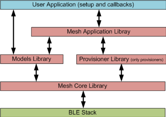
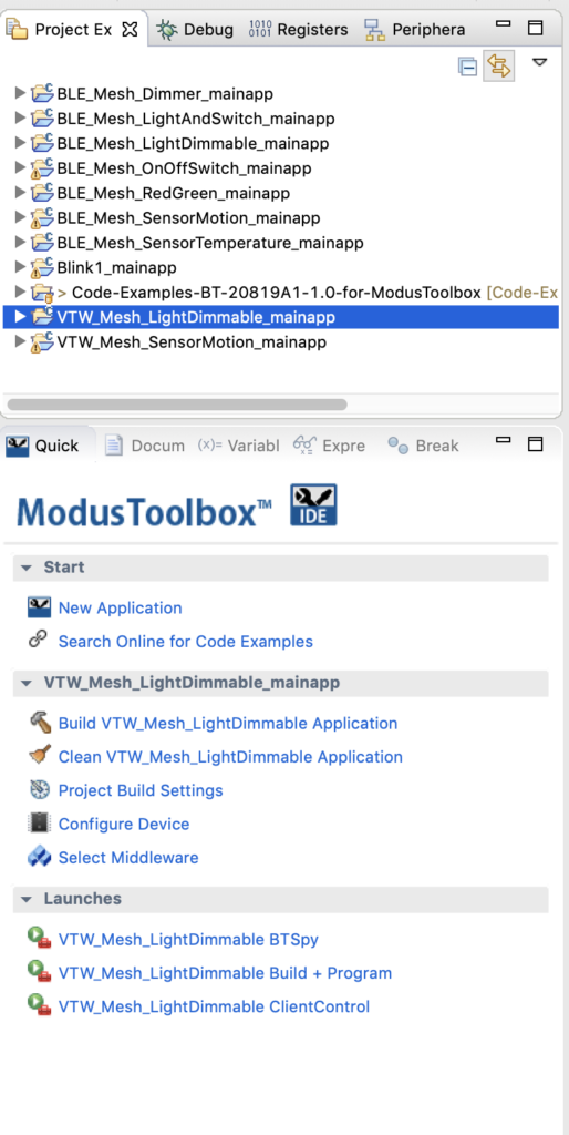
    Update

    There are several things that I don’t like about this program or need to be fixed.

    1. Make the user LED2 be LED1 and fix the fact that it is active low.
    2. Change the UUIDs of the Service and Characteristic to be legal 128-bit UUIDs
    3. Make the stdio print out the status of the connection (instead of the blinking LED1)
    4. Make the baud rate of standard i/o be 115200 instead of 9600

    First, fix the LED2 to be LED1.  Do this by commenting out all of the _alive_led code and switching the _actuated_led to be LED1.  Also set the state of the LED1 to 1 (meaning off because it is active low)

            //_alive_led(LED1, 1),
            _actuated_led(LED1, 1),

    The author of the example code has a function called blink which is executed by the event queue every 500ms, comment out that function

    /*
        void blink() {
            _alive_led = !_alive_led;
        }
    */

    And don’t inject events into the queue to run the blink function

            //_event_queue.call_every(500, this, &LEDDemo::blink);

    The LED on my board is active low… so instead of writing the value write the opposite of the value.

                _actuated_led = !*(params->data);
    

    It is illegal in Bluetooth to use 16-bit UUIDs without first registering them with the Bluetooth SIG and having them be “Assigned numbers”.  The author of this example program violated the specification by assigning the LED service UUID of 0xA000 and the LED characteristic UUID of 0xA001.  This is super annoying and I am not willing to be a slob.  To fix this modify ledservice.h to declare the UUIDs as UUID type instead of uint16_ts

        //const static uint16_t LED_SERVICE_UUID              = 0xA000;
        //const static uint16_t LED_STATE_CHARACTERISTIC_UUID = 0xA001;
    
        const static UUID LED_SERVICE_UUID;
        const static UUID LED_STATE_CHARACTERISTIC_UUID;

    Then initialize them in the main.cpp as 128-bit UUIDs using the const char * initializer.

    const UUID LEDService::LED_SERVICE_UUID("21c04d09-c884-4af1-96a9-52e4e4ba195b");
    const UUID LEDService::LED_STATE_CHARACTERISTIC_UUID("1e500043-6b31-4a3d-b91e-025f92ca9763");

    The original code has a blinking LED.  Which I dont really like.  Typically, I like to blink the LED when the device is advertising, and make it be solid when there is a connection.  However, as I only have one LED on my board, and I have allocated it to be the “_actuated_led”, I will use the UART to print out status changes.  To do this, I update the “onDisconnectionComplete” and “onConnectionComplete” events to print out that fact to stdio.

        void onDisconnectionComplete(const ble::DisconnectionCompleteEvent&) {
            _ble.gap().startAdvertising(ble::LEGACY_ADVERTISING_HANDLE);
            printf("DisconnectionCompleteEvent\n");
        }
    
        void onConnectionComplete	(	const ble::ConnectionCompleteEvent & 	event	)
        {
          printf("onConnectionComplete\n");
        }
    

    In order to set the stdio to use 115200 instead of 9600 you can change the default rate of the UART in the mbed_app.json.

      "CY8CPROTO_062_4343W": {
                "platform.stdio-baud-rate": 115200,
                "platform.default-serial-baud-rate": 115200
            },

    Here is the final version of main.cpp

    /* mbed Microcontroller Library
     * Copyright (c) 2006-2013 ARM Limited
     *
     * Licensed under the Apache License, Version 2.0 (the "License");
     * you may not use this file except in compliance with the License.
     * You may obtain a copy of the License at
     *
     *     http://www.apache.org/licenses/LICENSE-2.0
     *
     * Unless required by applicable law or agreed to in writing, software
     * distributed under the License is distributed on an "AS IS" BASIS,
     * WITHOUT WARRANTIES OR CONDITIONS OF ANY KIND, either express or implied.
     * See the License for the specific language governing permissions and
     * limitations under the License.
     */
    
    #include <events/mbed_events.h>
    #include <mbed.h>
    #include "ble/BLE.h"
    #include "LEDService.h"
    #include "pretty_printer.h"
    
    const static char DEVICE_NAME[] = "LED";
    
    static EventQueue event_queue(/* event count */ 10 * EVENTS_EVENT_SIZE);
    
    //const UUID::LongUUIDBytes_t testbytes = { 0x21, 0xc0, 0x4d, 0x09, 0xc8, 0x84, 0x4a, 0xf1, 0x96, 0xa9, 0x52, 0xe4, 0xe4, 0xba, 0x19, 0x5b } ;
    // {0x1e, 0x50, 0x00, 0x43, 0x6b, 0x31, 0x4a, 0x3d, 0xb9, 0x1e, 0x02, 0x5f, 0x92, 0xca, 0x97, 0x63}
    //const UUID LEDService::LED_SERVICE_UUID(testbytes,UUID::MSB);
    const UUID LEDService::LED_SERVICE_UUID("21c04d09-c884-4af1-96a9-52e4e4ba195b");
    const UUID LEDService::LED_STATE_CHARACTERISTIC_UUID("1e500043-6b31-4a3d-b91e-025f92ca9763");
    
    class LEDDemo : ble::Gap::EventHandler {
    public:
    
    
        LEDDemo(BLE &ble, events::EventQueue &event_queue) :
            _ble(ble),
            _event_queue(event_queue),
            //_alive_led(LED1, 1),
            _actuated_led(LED1, 1),
            _led_uuid(LEDService::LED_SERVICE_UUID),
            _led_service(NULL),
            _adv_data_builder(_adv_buffer) { }
    
        ~LEDDemo() {
            delete _led_service;
        }
    
        void start() {
            _ble.gap().setEventHandler(this);
    
            _ble.init(this, &LEDDemo::on_init_complete);
    
            //_event_queue.call_every(500, this, &LEDDemo::blink);
    
            _event_queue.dispatch_forever();
        }
    
    private:
        /** Callback triggered when the ble initialization process has finished */
        void on_init_complete(BLE::InitializationCompleteCallbackContext *params) {
            if (params->error != BLE_ERROR_NONE) {
                printf("Ble initialization failed.");
                return;
            }
    
            _led_service = new LEDService(_ble, false);
    
            _ble.gattServer().onDataWritten(this, &LEDDemo::on_data_written);
    
            print_mac_address();
    
            start_advertising();
        }
    
        void start_advertising() {
            /* Create advertising parameters and payload */
    
            ble::AdvertisingParameters adv_parameters(
                ble::advertising_type_t::CONNECTABLE_UNDIRECTED,
                ble::adv_interval_t(ble::millisecond_t(1000))
            );
    
            _adv_data_builder.setFlags();
            _adv_data_builder.setLocalServiceList(mbed::make_Span(&_led_uuid, 1));
            _adv_data_builder.setName(DEVICE_NAME);
    
            /* Setup advertising */
    
            ble_error_t error = _ble.gap().setAdvertisingParameters(
                ble::LEGACY_ADVERTISING_HANDLE,
                adv_parameters
            );
    
            if (error) {
                printf("_ble.gap().setAdvertisingParameters() failed\r\n");
                return;
            }
    
            error = _ble.gap().setAdvertisingPayload(
                ble::LEGACY_ADVERTISING_HANDLE,
                _adv_data_builder.getAdvertisingData()
            );
    
            if (error) {
                printf("_ble.gap().setAdvertisingPayload() failed\r\n");
                return;
            }
    
            /* Start advertising */
    
            error = _ble.gap().startAdvertising(ble::LEGACY_ADVERTISING_HANDLE);
    
            if (error) {
                printf("_ble.gap().startAdvertising() failed\r\n");
                return;
            }
        }
    
        /**
         * This callback allows the LEDService to receive updates to the ledState Characteristic.
         *
         * @param[in] params Information about the characterisitc being updated.
         */
        void on_data_written(const GattWriteCallbackParams *params) {
            if ((params->handle == _led_service->getValueHandle()) && (params->len == 1)) {
                _actuated_led = !*(params->data);
            }
        }
    /*
        void blink() {
            _alive_led = !_alive_led;
        }
    */
    private:
        /* Event handler */
    
        void onDisconnectionComplete(const ble::DisconnectionCompleteEvent&) {
            _ble.gap().startAdvertising(ble::LEGACY_ADVERTISING_HANDLE);
            printf("DisconnectionCompleteEvent\n");
        }
    
        void onConnectionComplete	(	const ble::ConnectionCompleteEvent & 	event	)
        {
          printf("onConnectionComplete\n");
        }
    
    private:
        BLE &_ble;
        events::EventQueue &_event_queue;
        //DigitalOut _alive_led;
        DigitalOut _actuated_led;
    
        UUID _led_uuid;
        LEDService *_led_service;
    
        uint8_t _adv_buffer[ble::LEGACY_ADVERTISING_MAX_SIZE];
        ble::AdvertisingDataBuilder _adv_data_builder;
    };
    
    /** Schedule processing of events from the BLE middleware in the event queue. */
    void schedule_ble_events(BLE::OnEventsToProcessCallbackContext *context) {
        event_queue.call(Callback<void()>(&context->ble, &BLE::processEvents));
    }
    
    int main()
    {
        printf("Example Bluetooth\n");
        BLE &ble = BLE::Instance();
        ble.onEventsToProcess(schedule_ble_events);
    
        LEDDemo demo(ble, event_queue);
        demo.start();
    
        return 0;
    }
    

    And LEDService.h

    /* mbed Microcontroller Library
     * Copyright (c) 2006-2013 ARM Limited
     *
     * Licensed under the Apache License, Version 2.0 (the "License");
     * you may not use this file except in compliance with the License.
     * You may obtain a copy of the License at
     *
     *     http://www.apache.org/licenses/LICENSE-2.0
     *
     * Unless required by applicable law or agreed to in writing, software
     * distributed under the License is distributed on an "AS IS" BASIS,
     * WITHOUT WARRANTIES OR CONDITIONS OF ANY KIND, either express or implied.
     * See the License for the specific language governing permissions and
     * limitations under the License.
     */
    
    #ifndef __BLE_LED_SERVICE_H__
    #define __BLE_LED_SERVICE_H__
    
    class LEDService {
    public:
        //const static uint16_t LED_SERVICE_UUID              = 0xA000;
        //const static uint16_t LED_STATE_CHARACTERISTIC_UUID = 0xA001;
    
        const static UUID LED_SERVICE_UUID;
        const static UUID LED_STATE_CHARACTERISTIC_UUID;
    
        LEDService(BLEDevice &_ble, bool initialValueForLEDCharacteristic) :
            ble(_ble), ledState(LED_STATE_CHARACTERISTIC_UUID, &initialValueForLEDCharacteristic)
        {
            GattCharacteristic *charTable[] = {&ledState};
            GattService         ledService(LED_SERVICE_UUID, charTable, sizeof(charTable) / sizeof(GattCharacteristic *));
    
            ble.gattServer().addService(ledService);
        }
    
        GattAttribute::Handle_t getValueHandle() const
        {
            return ledState.getValueHandle();
        }
    
    private:
        BLEDevice                         &ble;
        ReadWriteGattCharacteristic<bool> ledState;
    };
    
    #endif /* #ifndef __BLE_LED_SERVICE_H__ */