Pattern Agents are running a crowd funding effort for ThingSoC TSoC4L … help them here
Summary
One of the boards that the Pattern Agents guys sent me was a TSOC GROVEY I2CHUB : I2C Hub/Switch. In this post I will take you through the process that I went through to evaluate the board and build an interface to the ThingSoc TSoC 4L base board.
- Introduction to the TSoC Grovey I2CHUB
- Discussion of PCA9546A I2C
- Using the MiniProg-3 to interact with the PCA9546A
- Building a Command Line Interface (CLI) using the USB/UART
- Adding firmware to mimic the MiniProg-3 I2C list to the CLI
- Adding a “port change” feature to the CLI firmware
Introduction to the TSoC Grovey I2CHUB
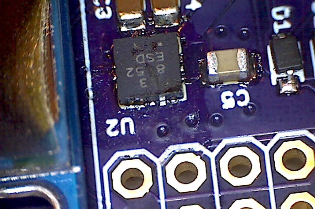
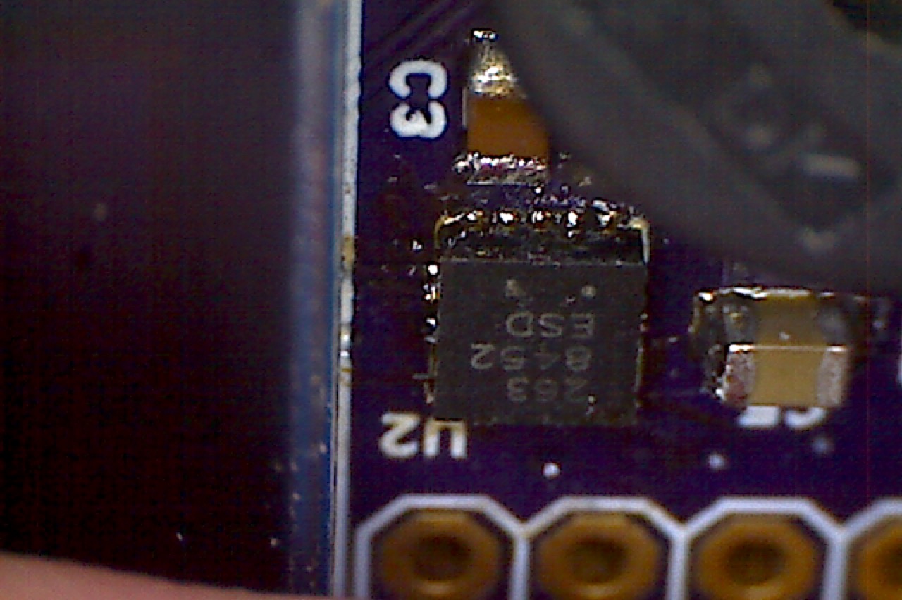
The ThingSoC I2C Hub is a ThingSoC Compatible (not Compliant) board that serves as a bridge from the base board to 4 separate programmable I2C busses using an NXP/TI 9546A bridge chip. Each of the I2C busses is attached via a SeeedStudio Grove connector. Grove is an ecosystem of sensors (Humidity, Temperature etc.) that are all? mostly? I2C connected.
Discussion of PCA9546A I2C
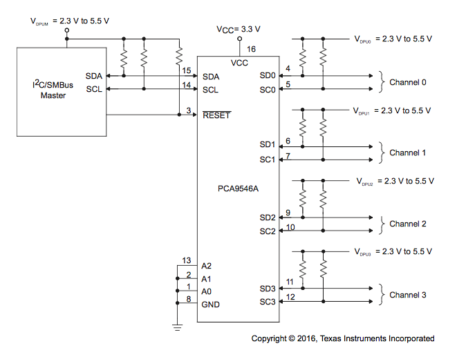
The PCA9546A is made by TI and NXP (or whatever they are calling themselves these days) and can be purchased for about $0.70 from Digikey, Mouser, or Arrow. The chip is pretty cool. It will let you connect your I2C master to 1 of 4 I2C busses. It will actually let you connect more than one bus at a time. This chip enables you to connect multiple slaves with the same address to your I2C master.
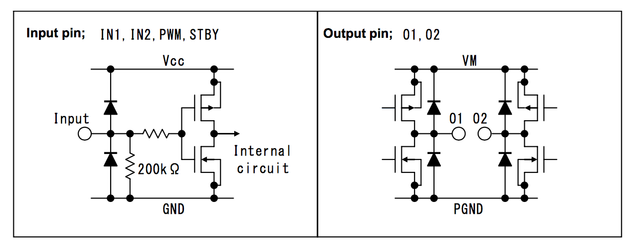
Here is a simplified picture from TIs datasheet.
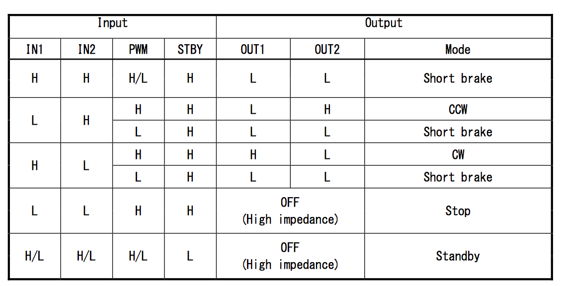
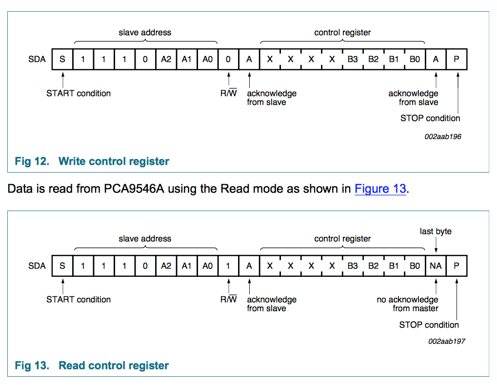
To control the system you just need to write into the control register with a bit mask. The bit masks contains which slaves busses you want switched on. Here is a screen shot from NXPs datasheet:
Using the MiniProg-3 to interact with the PCA9546A
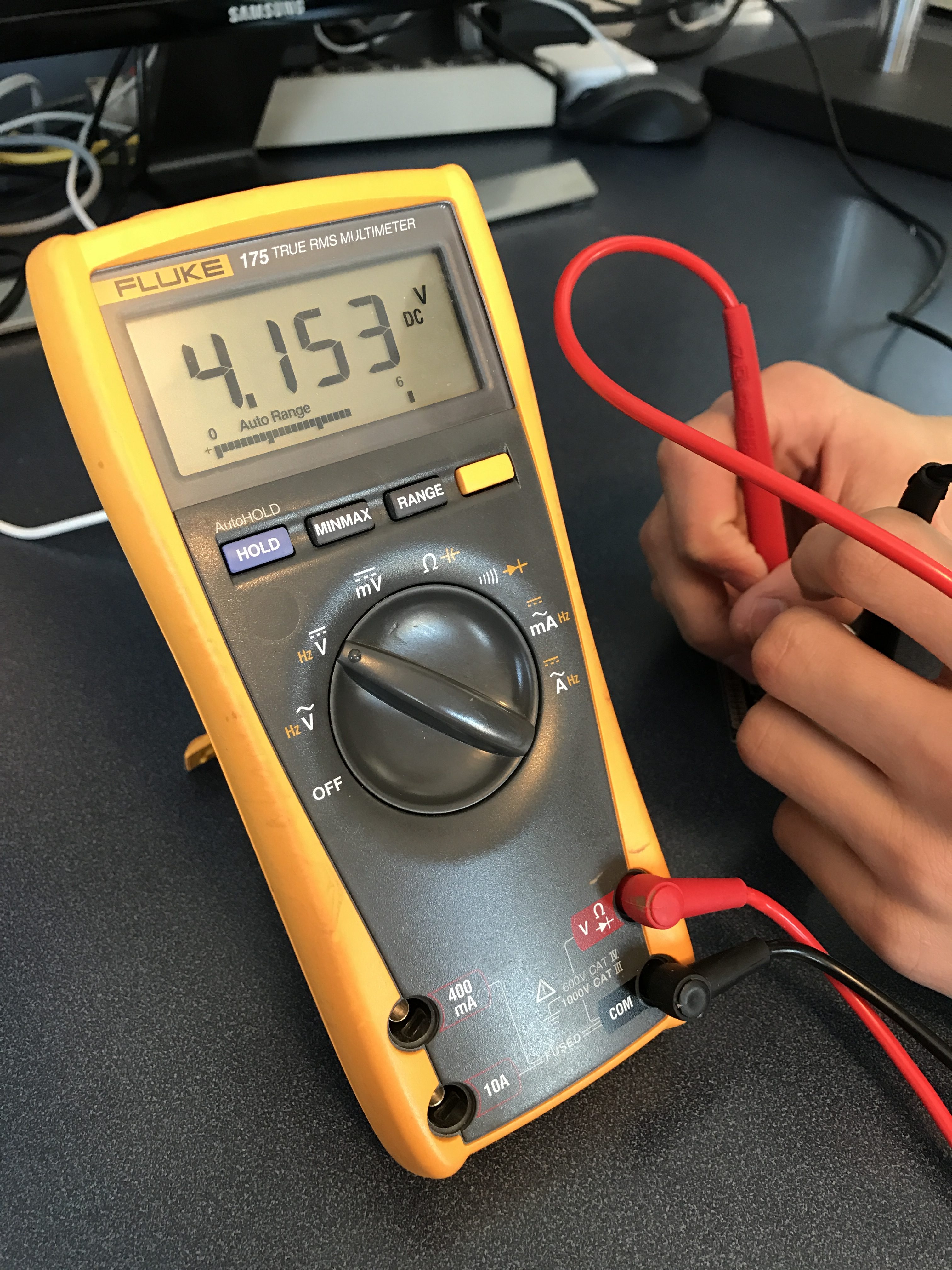
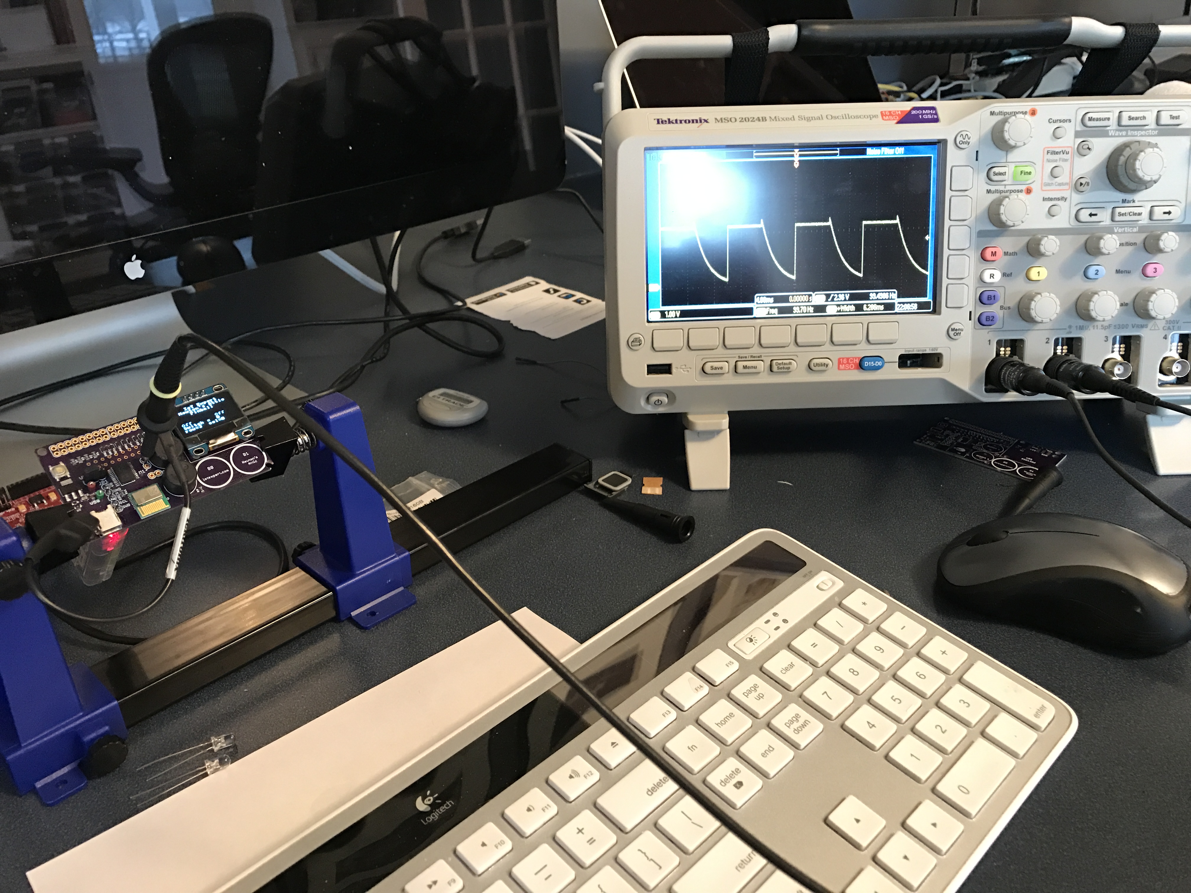
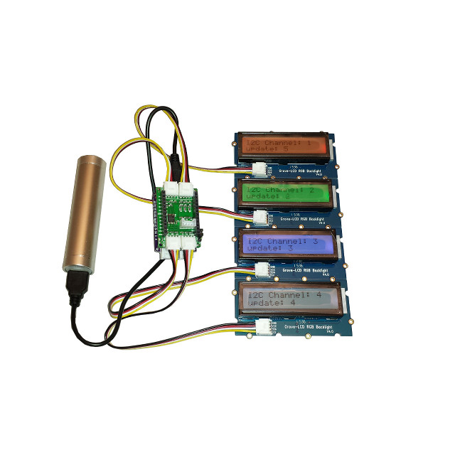
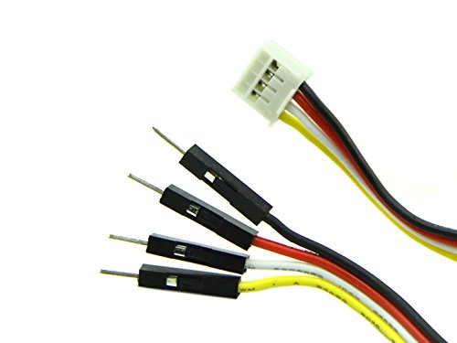
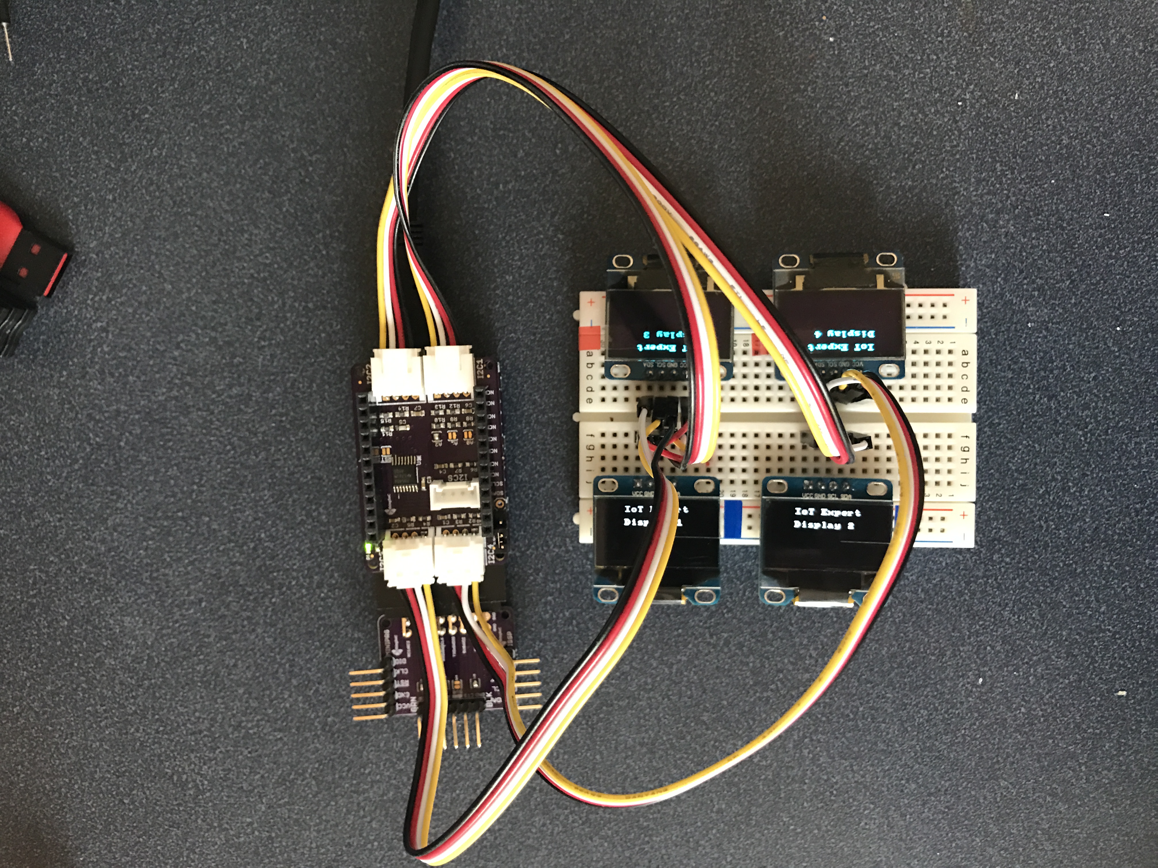
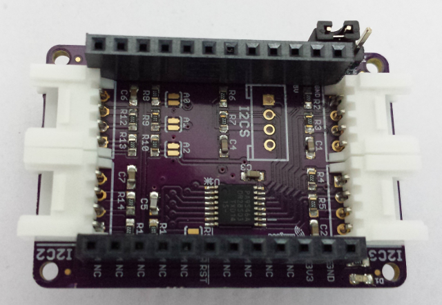
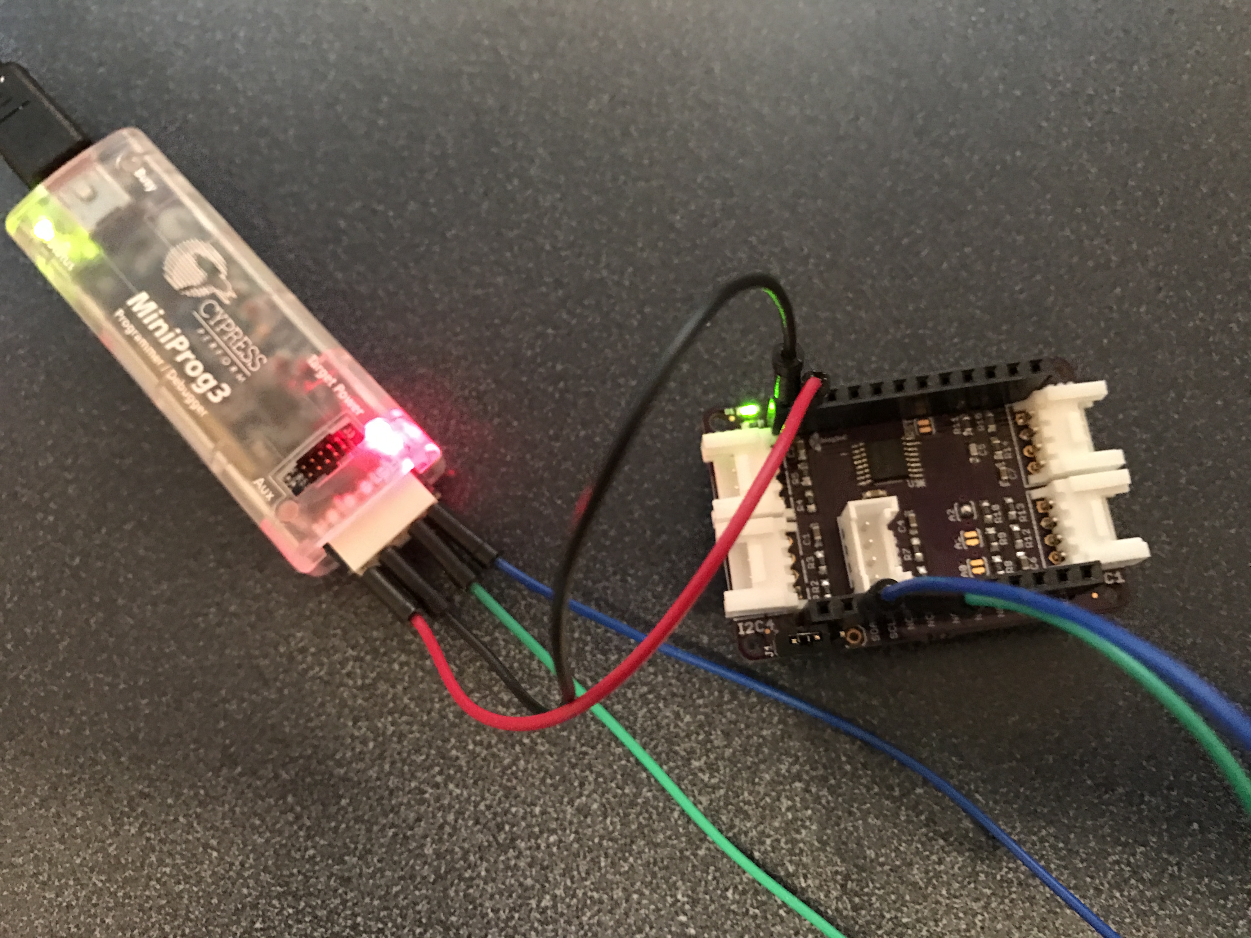
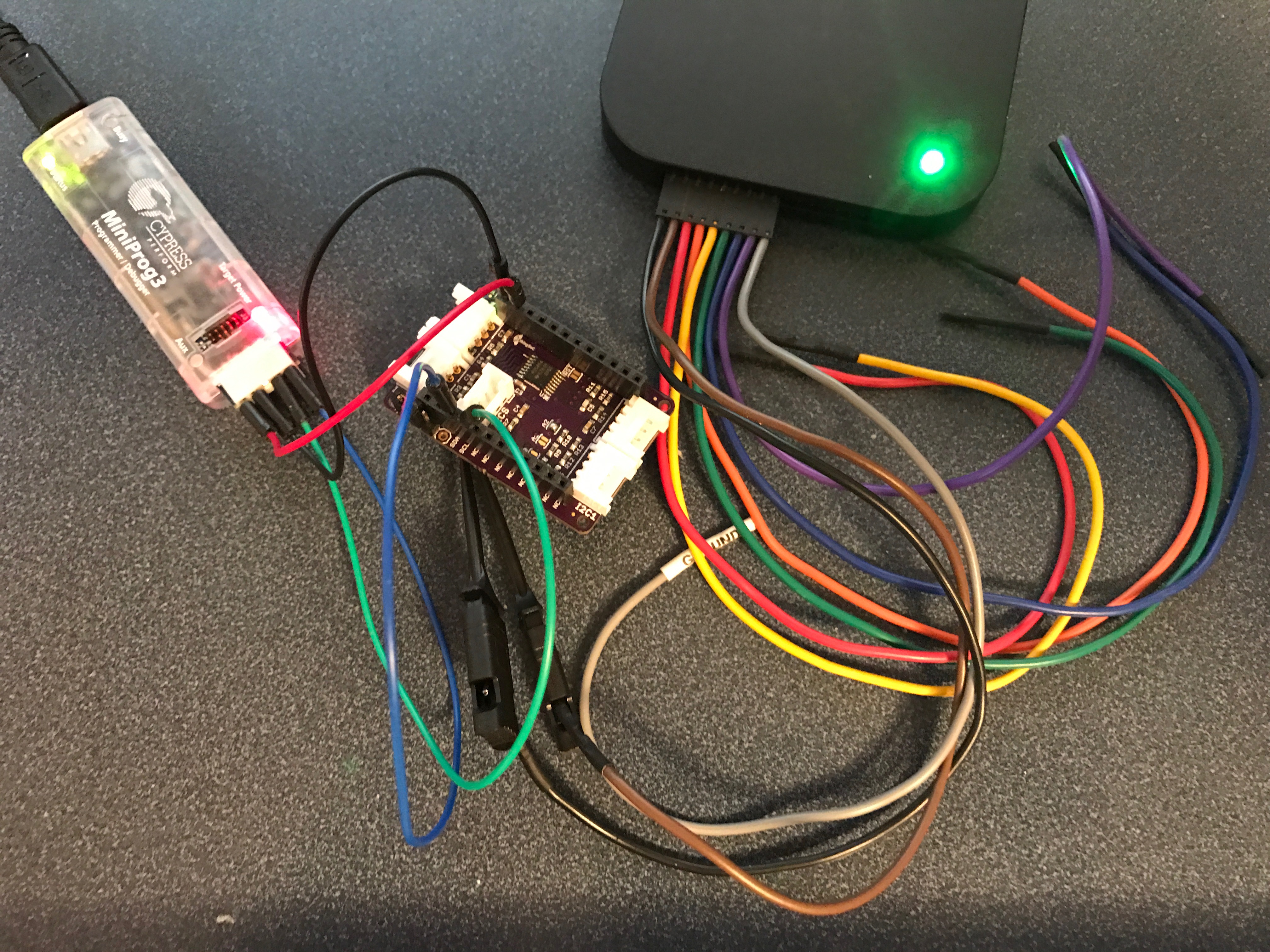
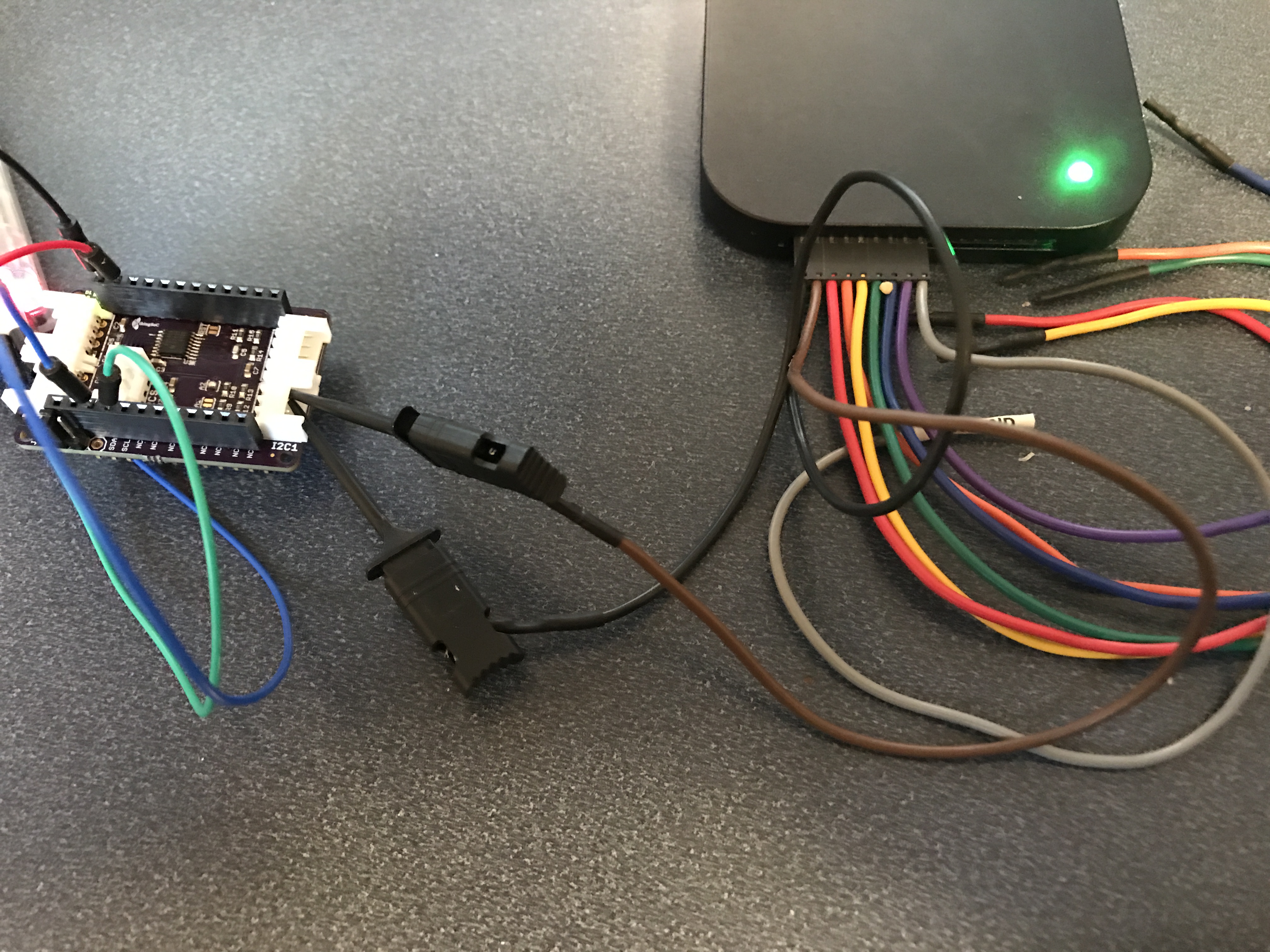
I start the whole firmware journey by using a MiniProg-3 as an I2C<–>USB bridge. This allows me to type I2C commands in the Bridge Control Panel which go directly to the chip (without writing firmware). In the picture below you can see that I have the MiniProg-3 attached to the ThingSoC board using jumper wires. I also use the MiniProg-3 to power the board.
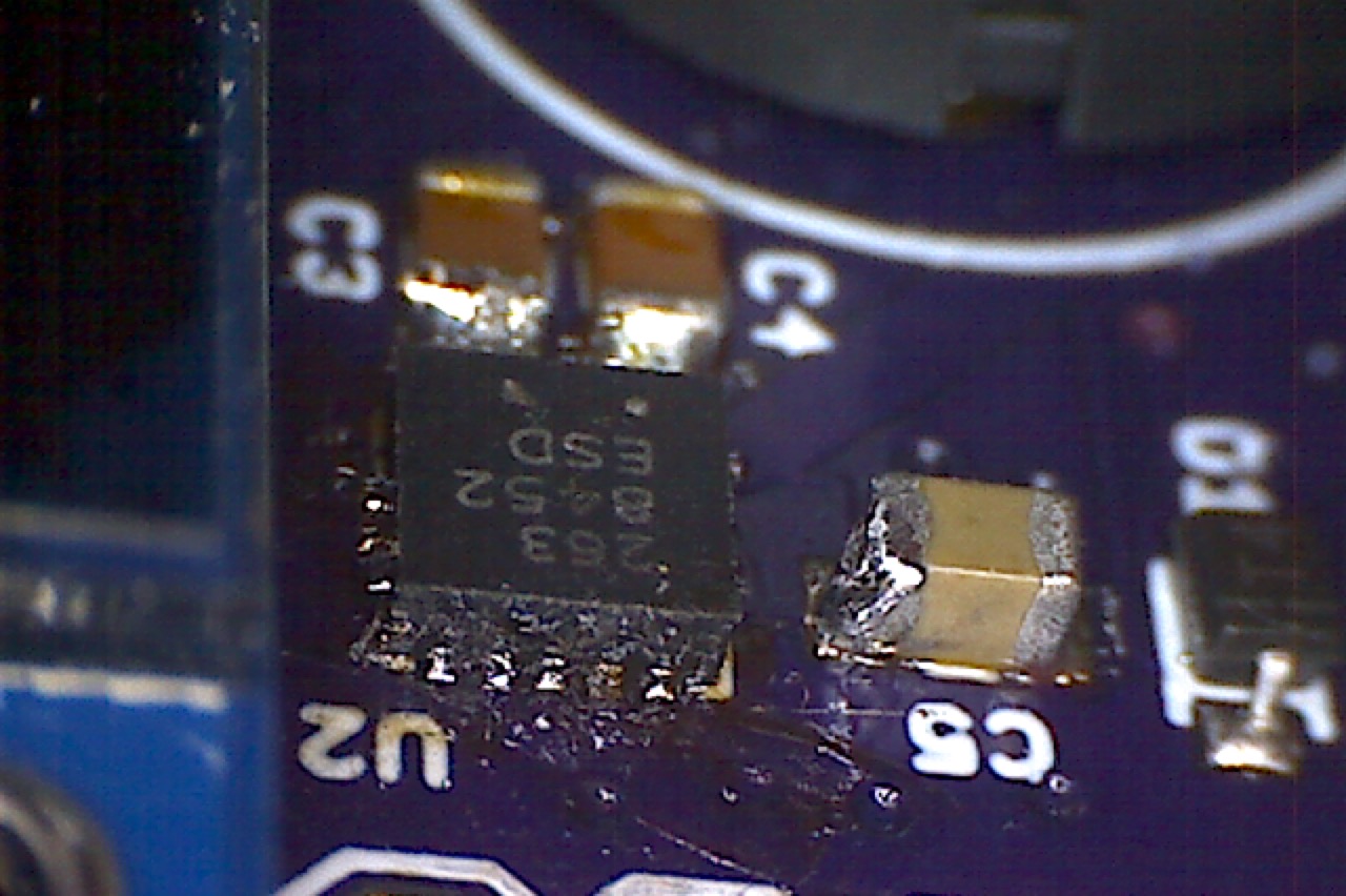
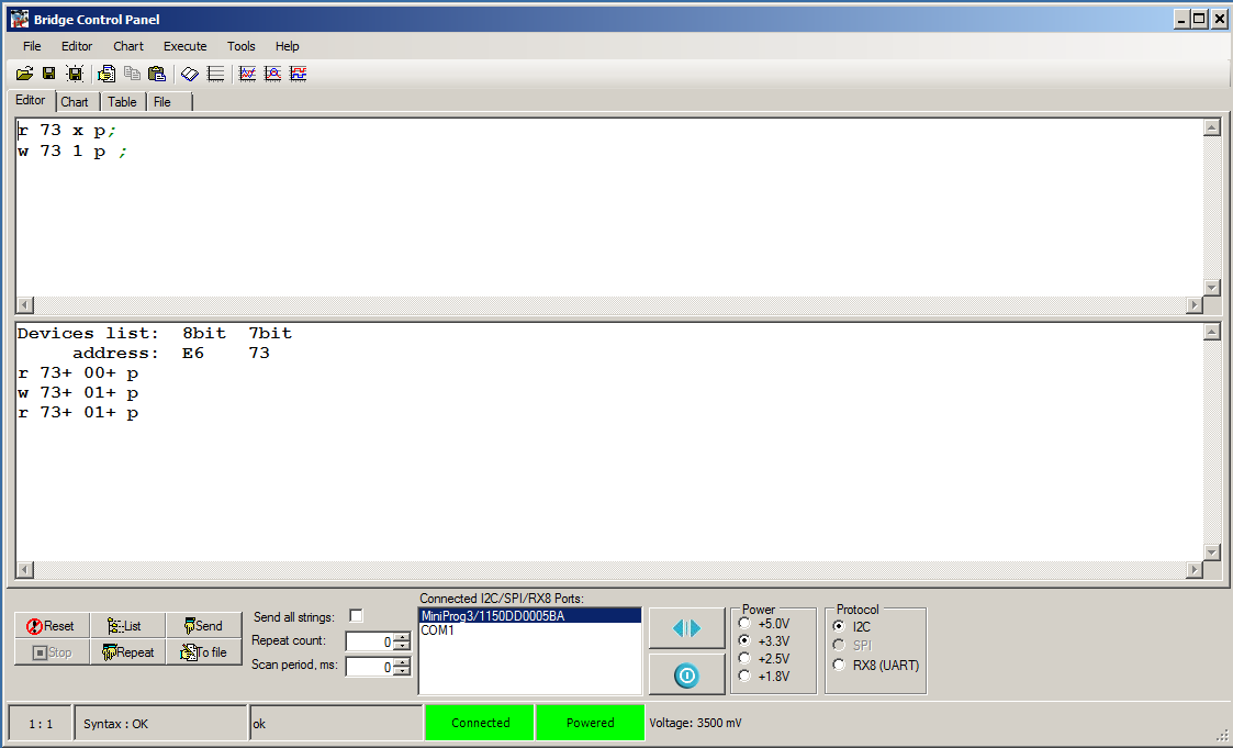
When I press “List”, the Bridge Control Panel probes all of the I2C addresses. If a device ACKs, it prints out that fact in the output window. In the picture below you can see that PCA9546A is attached at address 0x73. I then read and write the control register, which also works as expected.
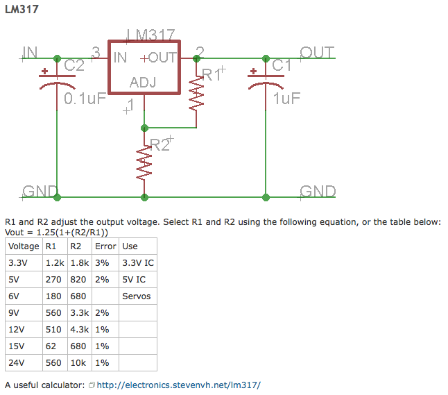
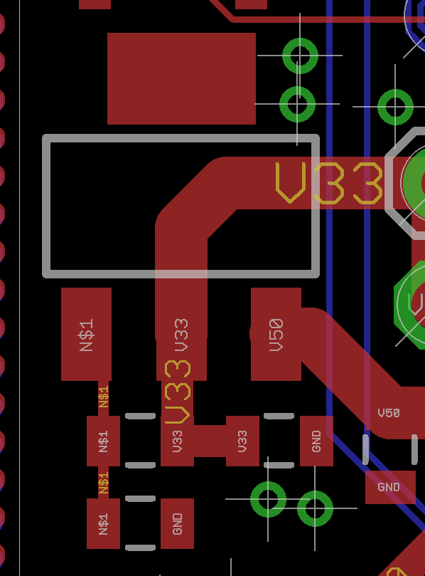
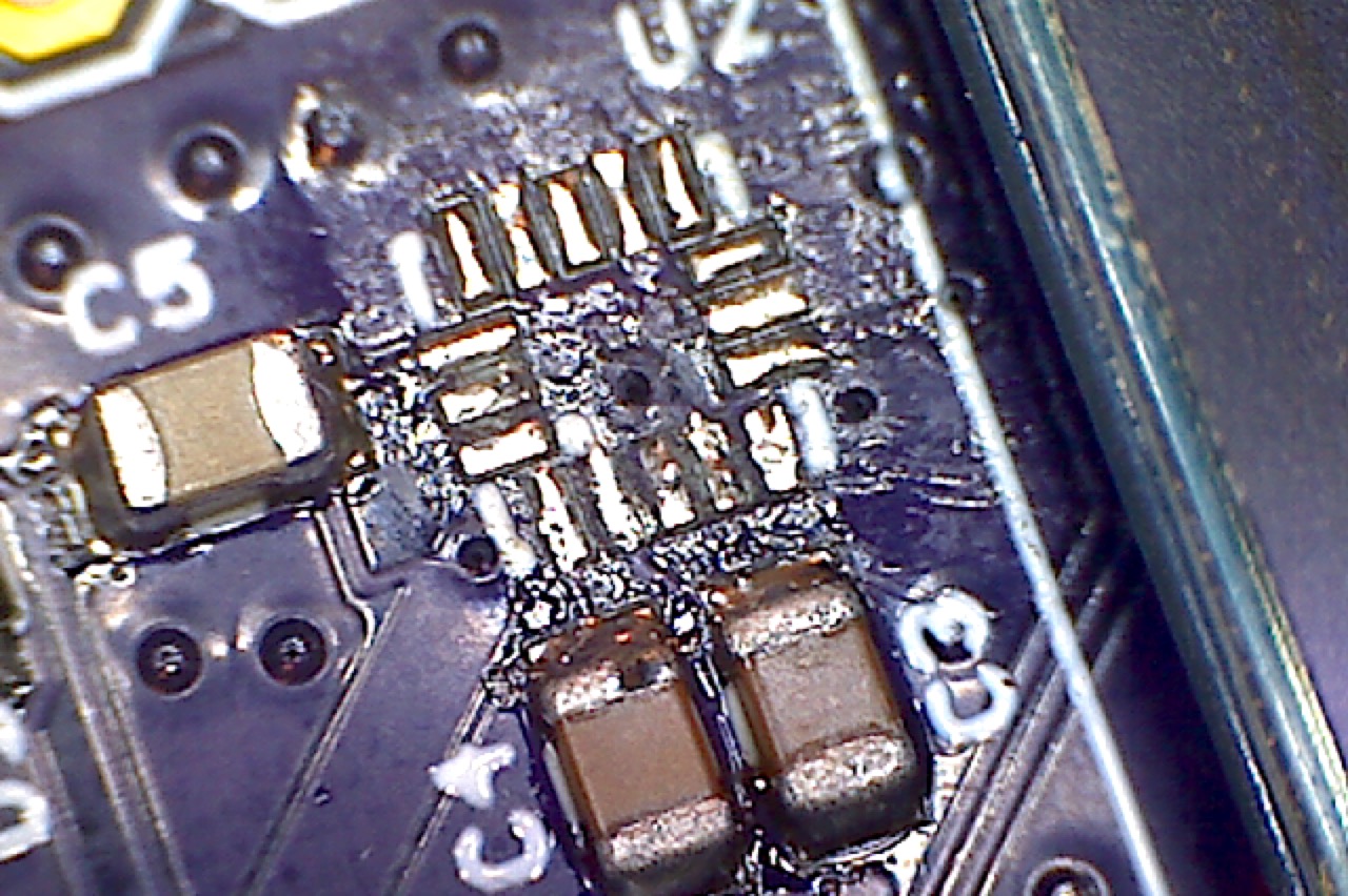
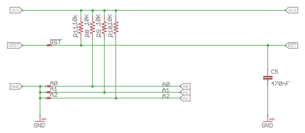
The address 0x73 makes sense as you can see that (in the picture above) there is a blob of solder on “A2” which pulls it low (instead of the default high). Here is that part of the schematic:
Building a Command Line Interface (CLI) over the USB/UART
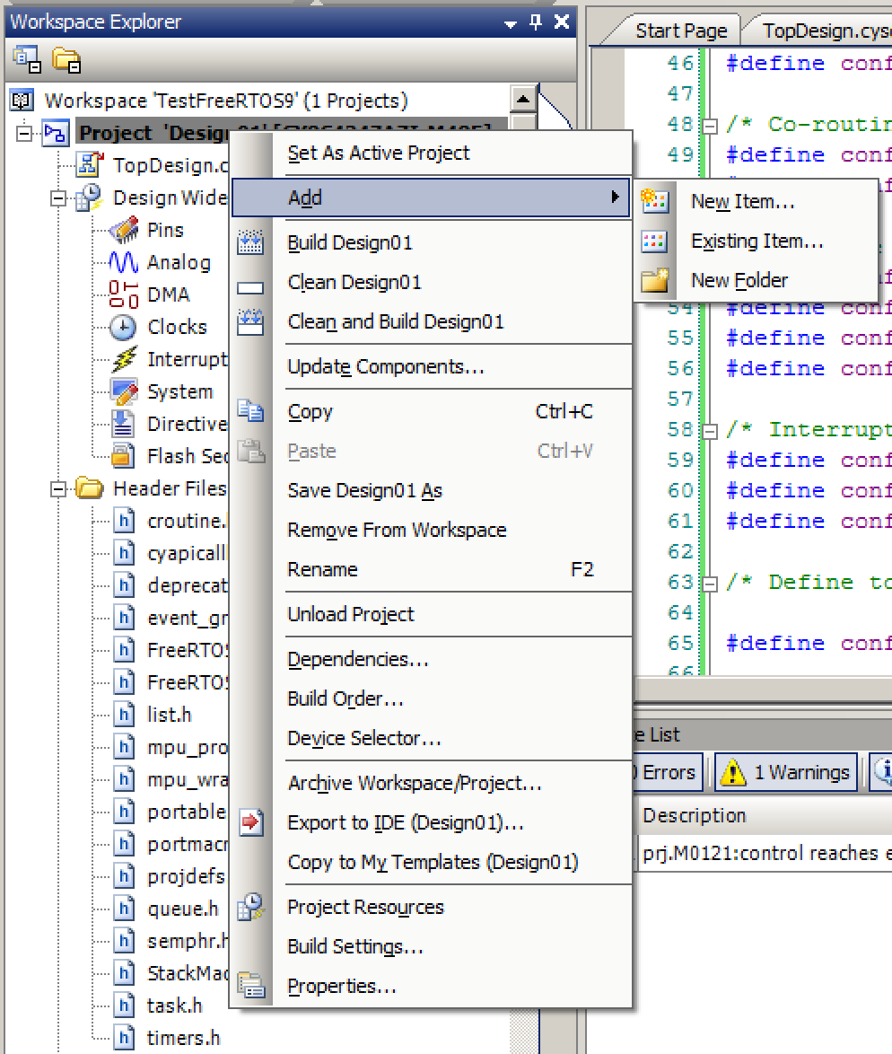
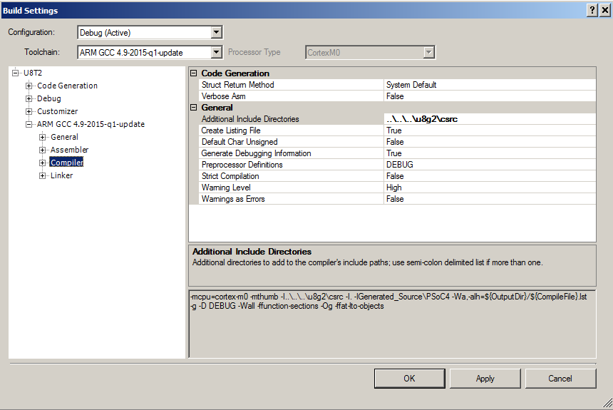
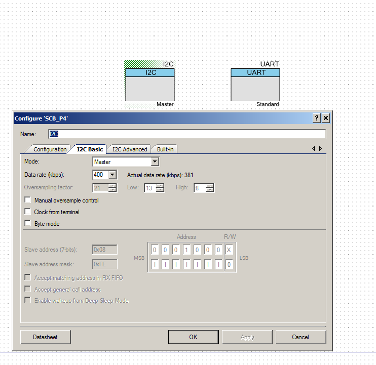
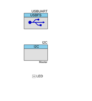
Now I am ready to build a command line interface using the USB <–> UART Bridge. First, I make a schematic with the USB-FS (Full Speed), LED and I2C components. Notice that the USBFS is setup as a USBUART. The I2C is configured as a Master.
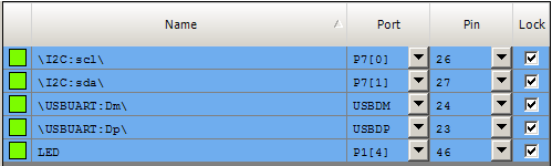
The Pins are selected as:
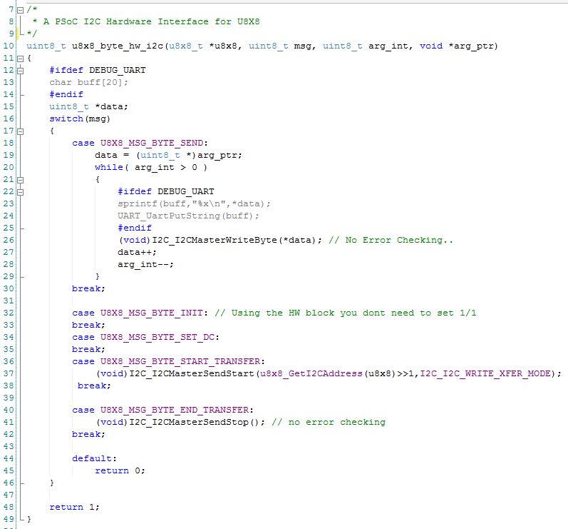
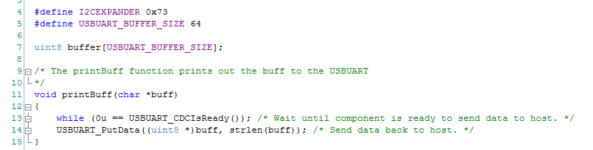
Next is a helper function to printout text via the CDC UART:
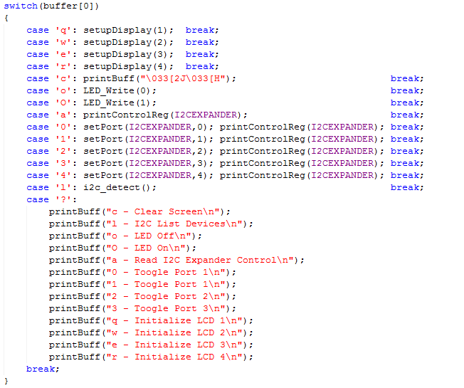
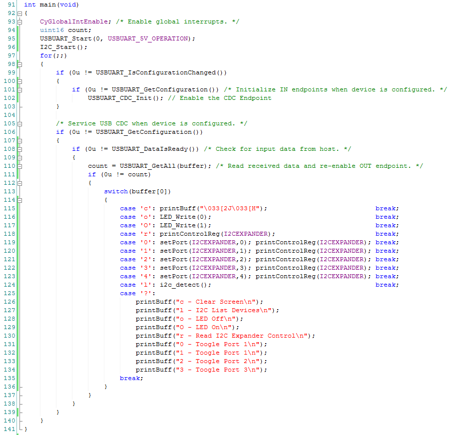
Then I write a little bit of firmware for the CLI. The function just reads from the UART and, if the user has pressed a button, then it issues that command.
Lines 99-103 get the USBUART going, and deal with changes (e.g. unplug events).
The only thing that you might not have seen is the “Clear Screen”. I just send out the escape sequence (old school) for clear screen and move home from the VT100 Escape Codes.
Adding firmware to mimic the MiniProg-3 I2C list to the CLI
When you press “List” in the Bridge Control Panel, what happens? Although I have been using the Bridge Control Panel for years I wasn’t exactly sure. To find the answer, I plugged in my Saleae Logic 16 and watched the output.
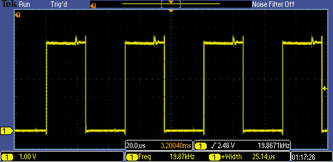
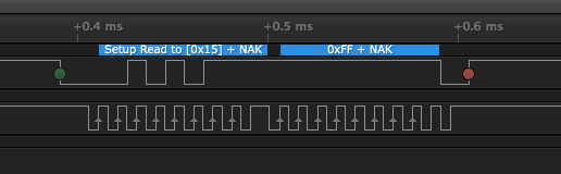
In this screenshot from the Saleae Logic output screen, you can see that the Bridge Control Panel sends out a “Read 0x15” which was NAKed.
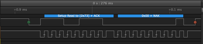
In this screen shot you can see that when the “Read 0x73” occurs, that the PCA9456A ACKs which tells the Bridge Control Panel that the device is there.
While I was writing the entry, I looked around at several implementations. It appears that sometimes people send “Write Address” instead of “Read Address”. I wasn’t sure exactly what was right, so I consulted Dr. Zwave. He really should go by Dr. I2C since that is what he did at Cypress. Anyway, he pointed out that you will hang the I2C bus if you try a Read and then don’t read the next byte. With a write you don’t actually need to keep writing. I decided to follow his instructions.
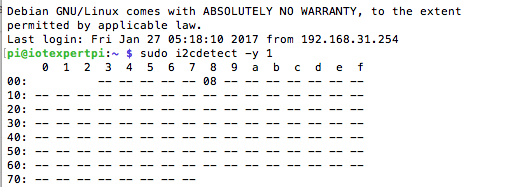
I have always liked the output of the Raspberry Pi I2CDetect command. Here is a screen shot from one of my Raspberry Pi’s where a PSoC4 is attached on I2C Address 0x8. I am not totally sure why the command does not probe addresses 0x00-0x02 (comment with the answer and Ill send you a devkit)
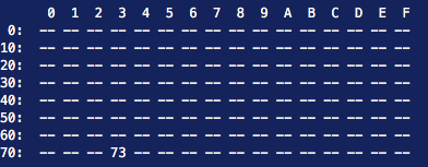
The implementation of i2c_detect on the PSoC4L is pretty simple. All I need to do is iterate through all of the addresses from 0->0x7F. Then attempt to write. If a device ACKs then printout the address, otherwise move on. Instead of one big loop, I split it up into two loops to make the printing a little bit simpler. Here is the code:
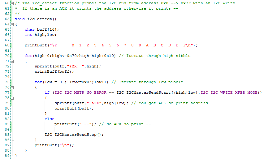
Now, when I press “l” on the CLI, it probes all of the legal addresses on the I2C bus from the PSoC4L. You can see that only the PCA9546A at address 0x73 is active. How cool is that?
Adding a “port change” feature to the CLI firmware
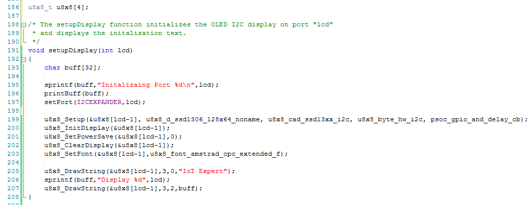
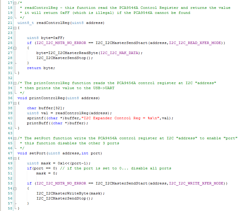
The last block of code adds three functions which let me control the PCA9546A control register.
To test the whole thing, I attach the Saleae Logic Analzer to I2C Port1. Then I probe to make sure that I can attach and unattached the bus.
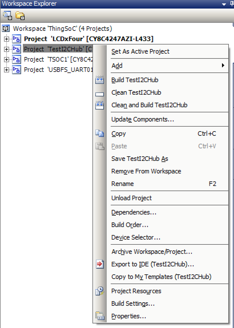
You can find all of the projects in the TSoC Series at my GitHub ThingSoC repository git@github.com:iotexpert/ThingSoC.git