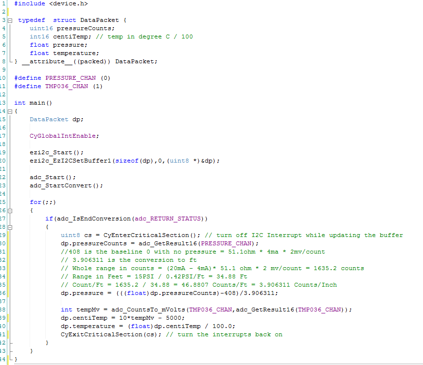
In the previous post I discussed the process that I used to test the bootloader firmware. In this post I will walk you through testing the actual application firmware. As I started working on this post I decided to remind myself of the format of the EZI2C buffer. Here it is:

The first thing that I immediately noticed was that I did something really dumb. Specifically I named one of the fields “float pressure” when it is really “float inches”. Oh well. The DataPacket structure is composed of 4 variables, two of them are 2-byte unsigned integers and two of them are 4-byte float. As this PSoC is an ARM chip, all of the variables are stored in little endian format-meaning that the Most Significant Byte (MSB) is last.
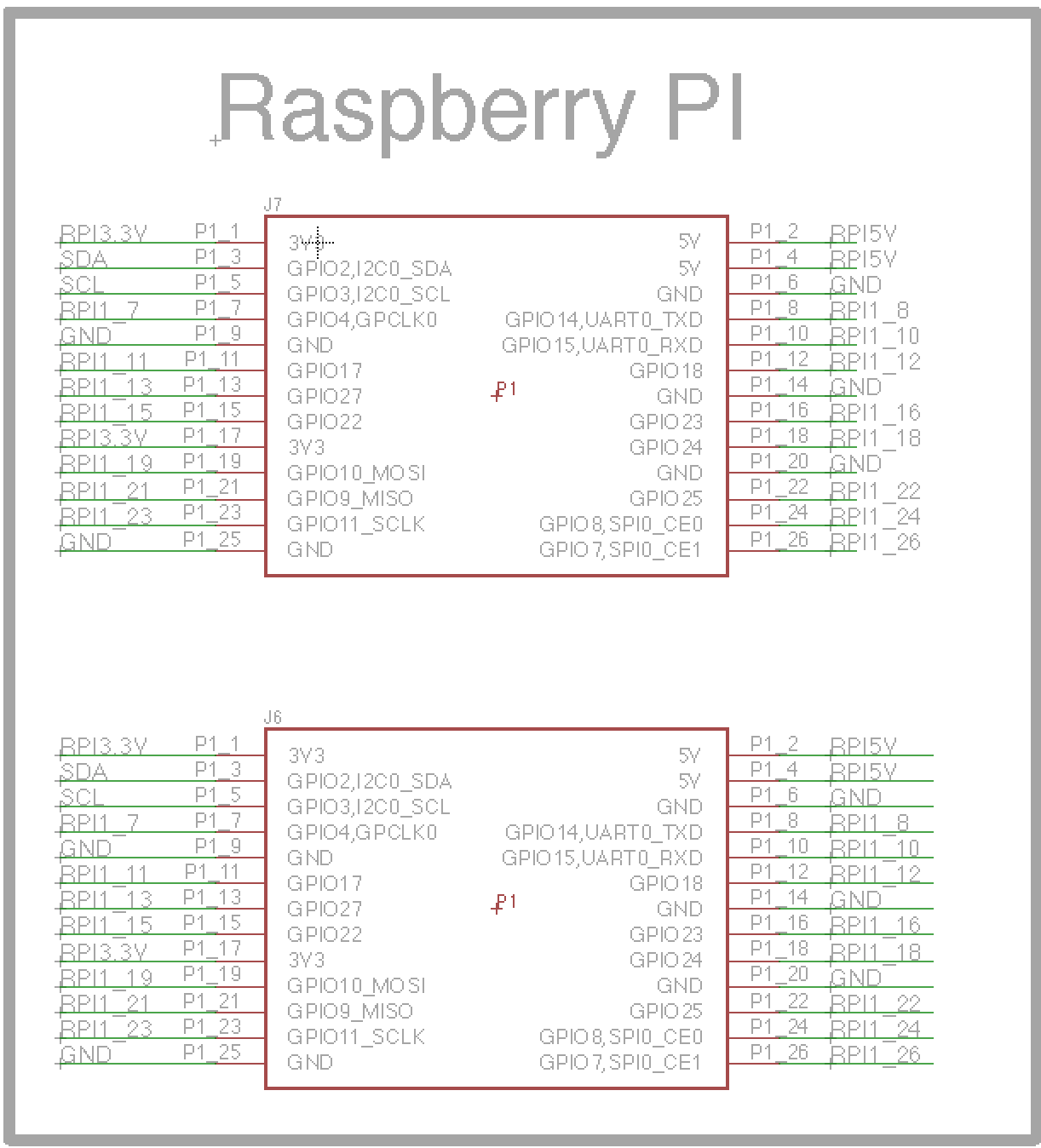
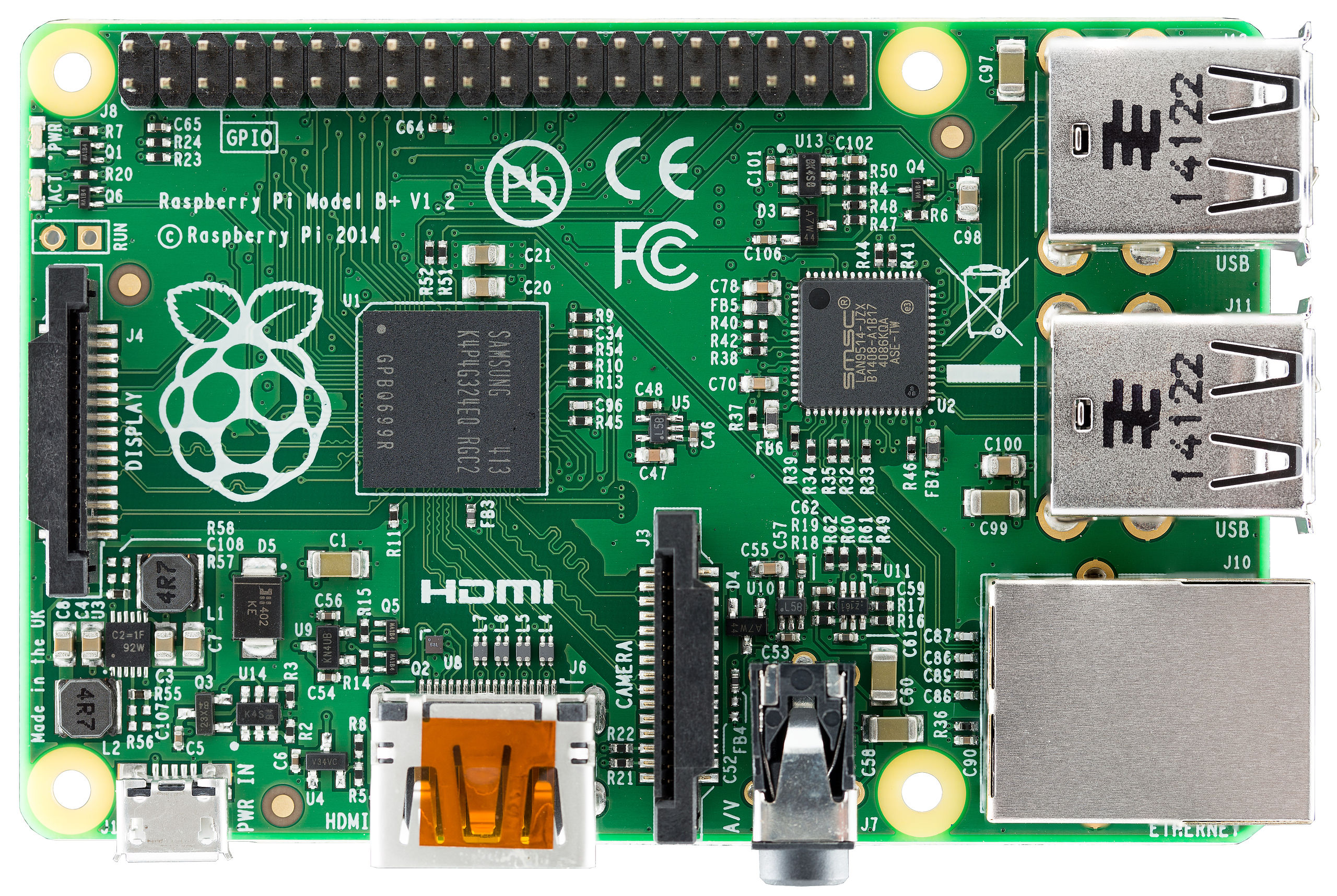
To help test the firmware, I will use a program called the Bridge Control Panel (BCP). The BCP is delivered as part of the PSoC Creator installation and is available under the Start->All Programs->Cypress menu. The BCP can talk to a Miniprog 3 (or any of the Cypress programmers) via the USB port and then bridge to the I2C bus. It can then act as an I2C master- in my case it will be emulating the Raspberry Pi I2C Master.
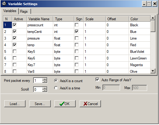
After starting the BCP, I first configure the “chart->variable settings”. This allows me to setup names and sizes of the EZI2C registers that I want to read from the PSoC. You can see that I added one variable to correspond to each variable in the DataPacket structure. In the BCP, an “int” is the same as an ARM int16 aka a two byte integer. I also select “sign” to indicate that the tempCenti is int16 (not uint16).
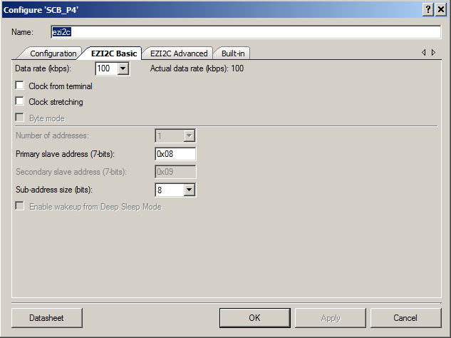
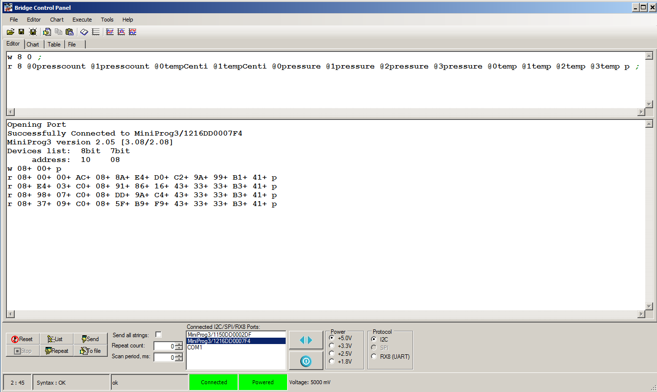
After setting up the variables, I first make sure that the BCP is talking to the PSoC4 by pressing “list” button on the BCP. When I click that button, the BCP tries to read from all of the 127 valid I2C addresses. If it gets an “ACK”, then it reports that it can talk to that device. On the screen below you can see that it sees “address: 10 08” which is the I2C address of my PSoC4.
The next step is to tell the BCP how to read the EZI2C registers. First I write a 0 to address 8 with the “w 8 0;” command. This sets the “data pointer” t0 0, meaning the start of the register space. I then issue command to read 12 bytes, each byte has a name that corresponds to a byte in the “variables” configured in the previous step. An example is “@0presscount” which corresponds to the least significant byte of the presscount variable and “@1presscount” which corresponds to the most significant byte of the presscount variable.
After setting up the variables, I press “return” to issue the command. The BCP returns “r 08+ 00+ 00+ AC+ 08+ 8A+ E4+ D0+ C2+ 9A+ 99+ B1+ 41+”. What does that mean? The R means that it did a read. The 08+ is the address of the I2C and the + means and “ACK”. Each of the other bytes+ are the other 12 bytes read in the command. I use this website to covert the 4-byte hex float(s) to decimal and I get:
- pressCount = 0x0000 : There is 0 volts attached to the input which is true
- tempCenti = 0x08AC = 2200 (that makes sense 22.2 degrees c * 100 ~= 2200)
- pressure = 0xC2D0E48A = -104.44636535644531 … that makes sense rememberdp.pressure = (((float)dp.pressureCounts)-408)/3.906311:
- temp = 0x41b1999A = 22.200000762939453 c = 71.9f [ok that makes sense]
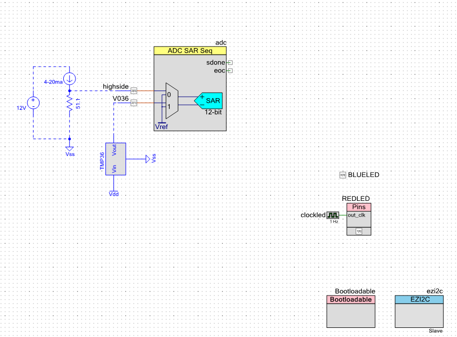
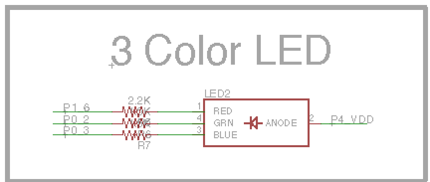
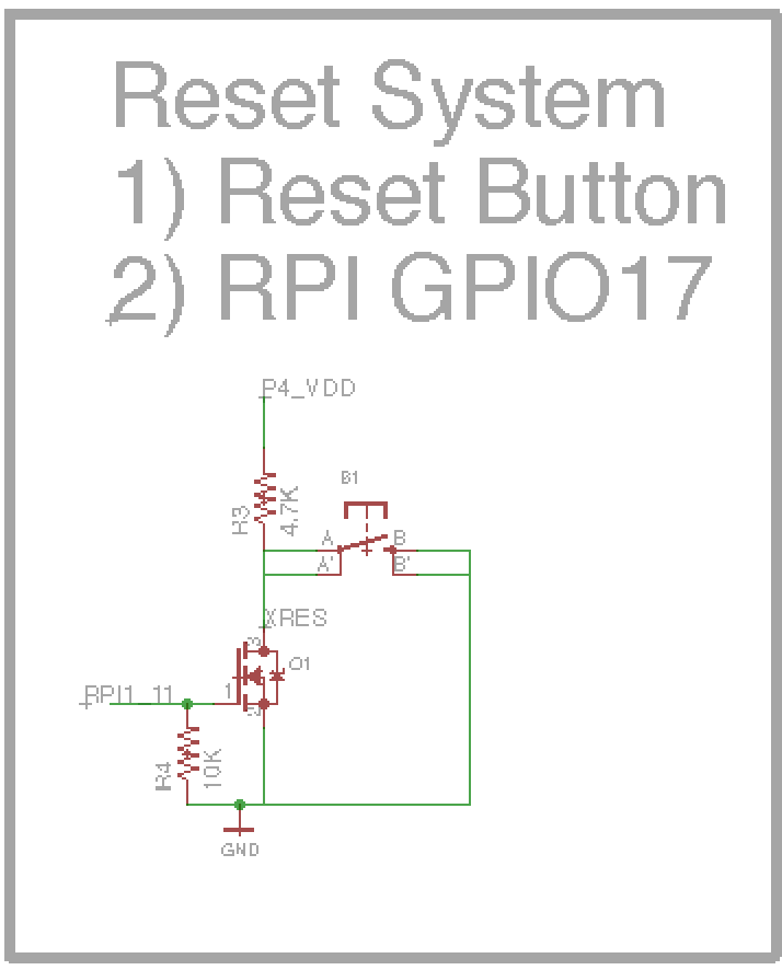
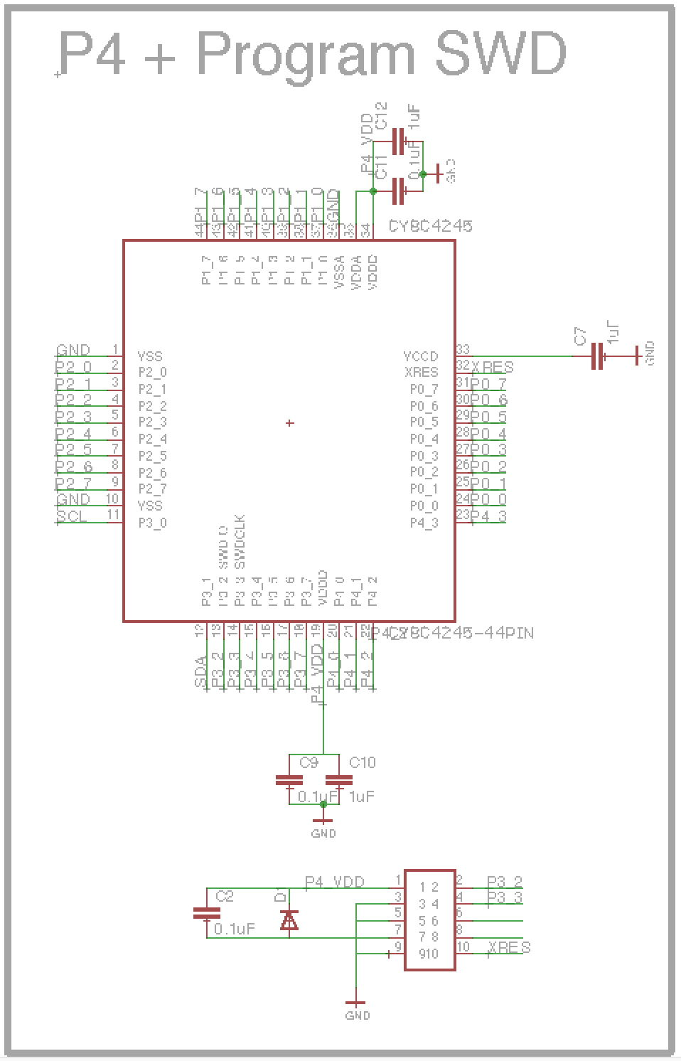
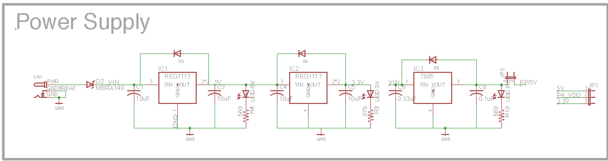
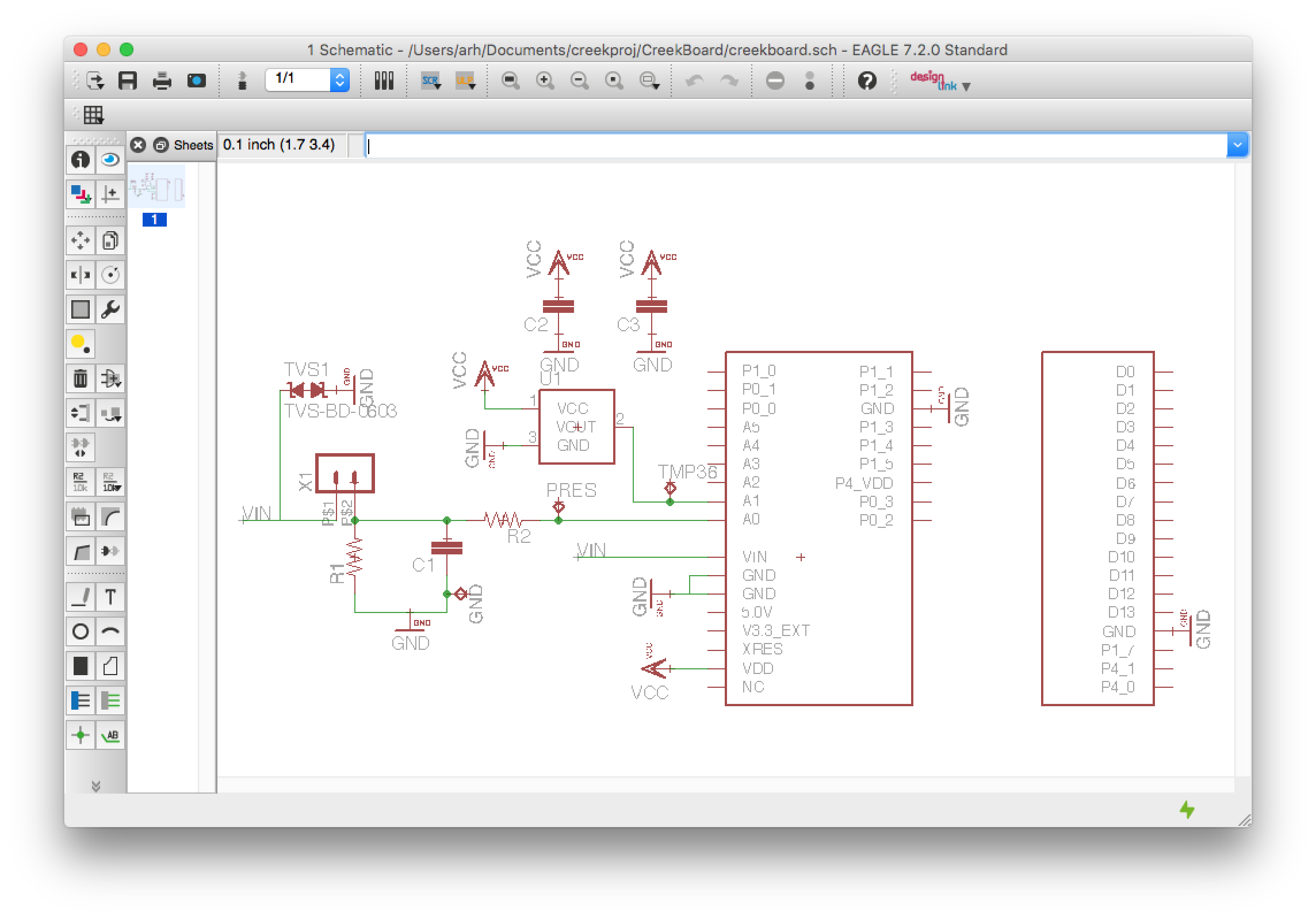
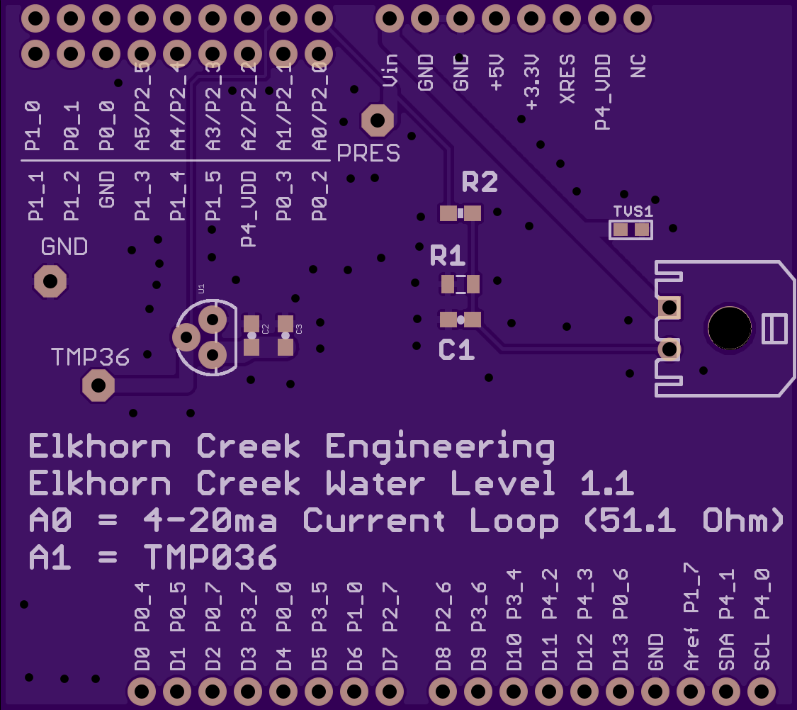
The next step is to attach a bench power supply to the pressure input (I bought this one from eBay). I will use the variable voltage to simulate different pressures. Recall from the schematic that the pressure sensor acts as a current source that is then driven into a 51.1 ohm resistor. Here is the schematic:
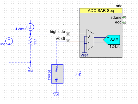
With this setup if I put in 0.51V on the “high side” I should get [V=IR] 0.51V = I * 51.1Ohm so I= 0.01 A. You can see from the picture that is what I get (or pretty damn close). When I press return on the bridge control panel (see it in the screen shot above) I get “r 08+ E4+ 03+ C0+ 08+ 91+ 86+ 16+ 43+ 33+ 33+ B3+ 41+” which means
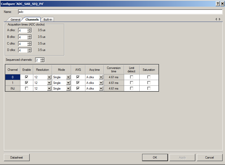
- pressCount = 0x03E4 = 996 counts. The range of the ADC is 4096 counts (in single ended mode) and 0 –> 2.048V so 996 counts is 0.498v
- tempCenti = 0x08C0 = 2200 (that makes sense 22.2 degrees c * 100 ~= 2200)
- pressure = 0x43168691 = 150.52565002441406 [that works… remember the equation]dp.pressure = (((float)dp.pressureCounts)-408)/3.906311
- temp = 0x41B33333 = 22.399999618530273 c = 72.3f [ok that makes sense]

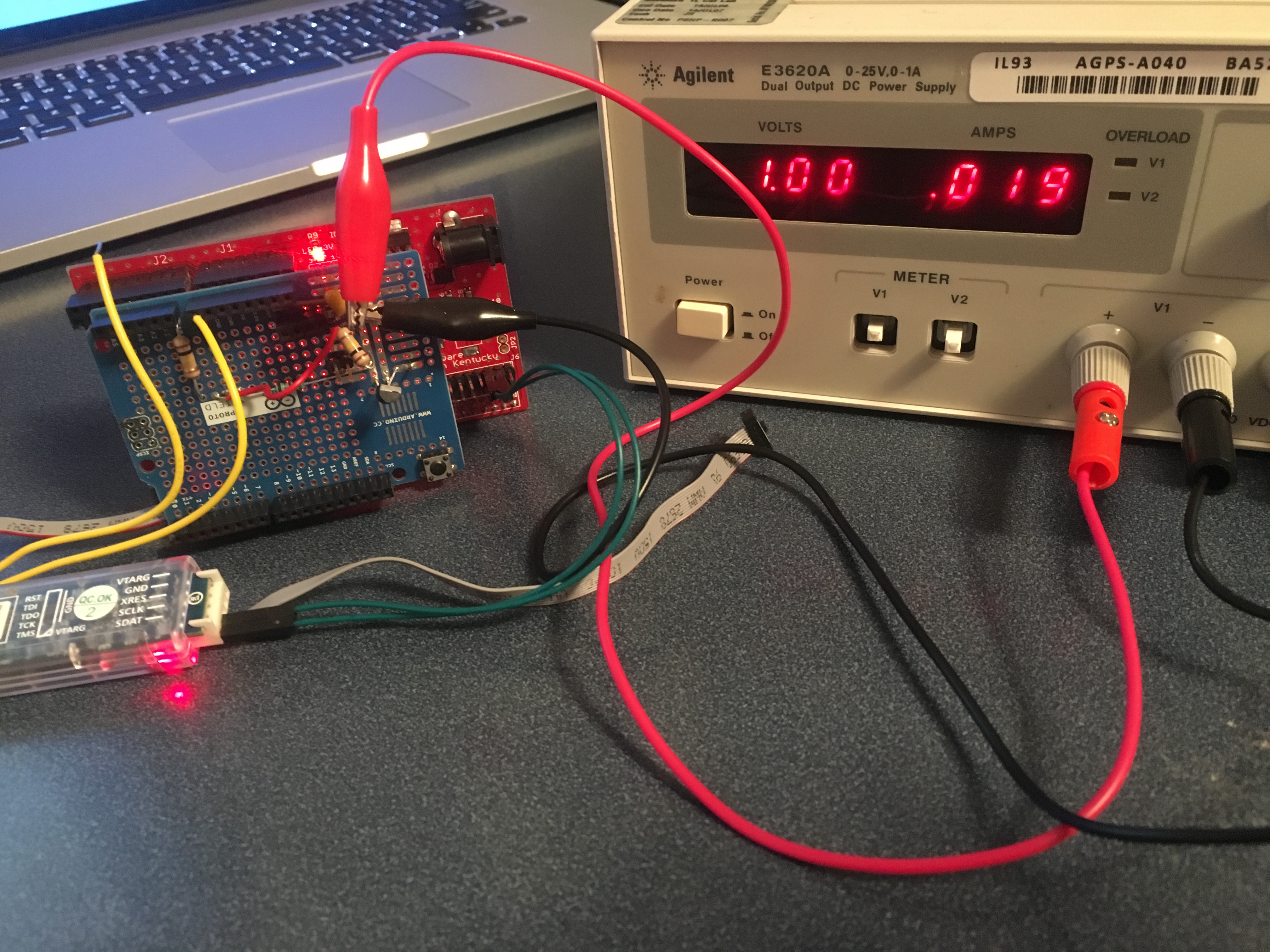
For the last test of the pressure sensor input I put the variable supply to 1.0V which makes 0.019 mA. Once again V=IR 1V/51.1Ohm = 0.0196 A. Ok Ohms law still works. Then I press return and I get “r 08+ 98+ 07+ C0+ 08+ DD+ 9A+ C4+ 43+ 33+ 33+ B3+ 41+ p”. When I decode that I get
- pressCount = 0x0798 = 1944 counts. The range of the ADC is 4096 counts (in single ended mode) and 0 –> 2.048V so 1944 counts is 0.972v (that is pretty damn close)
- tempCenti = 0x08C0 = 2240 (that makes sense 22.4 degrees c * 100 ~= 2240)
- pressure = 0x43C49ADD = 393.2098693847656 [that works… remember the equation]dp.pressure = (((float)dp.pressureCounts)-408)/3.906311:
- temp = 0x41B33333 = 22.399999618530273 c = 72.3f [ok that makes sense]
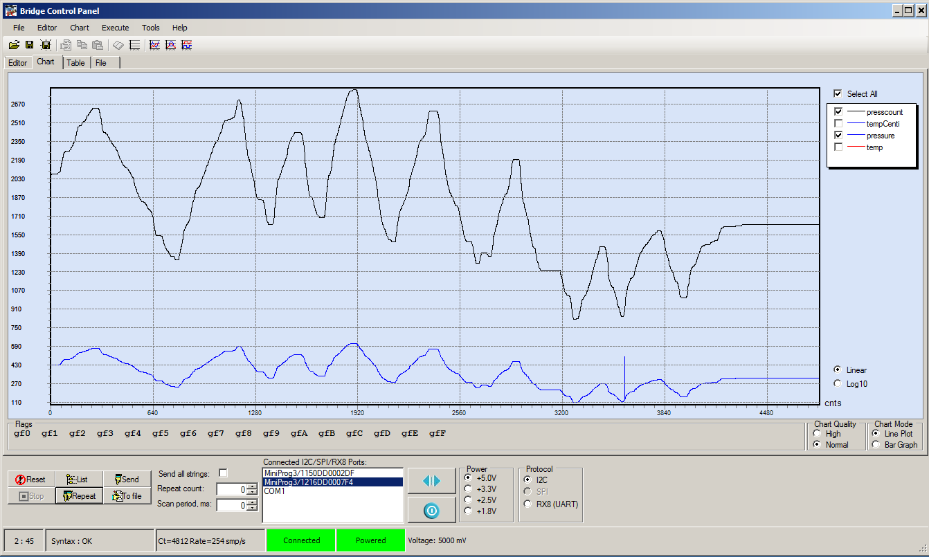
In the next test I will go into graphing mode and use the “repeat” button to run I2C reads as fast as possible. I will then sweep the voltage on the bench power supply and plot the pressure and the counts to make sure that makes sense. It looks good, here is the plot:
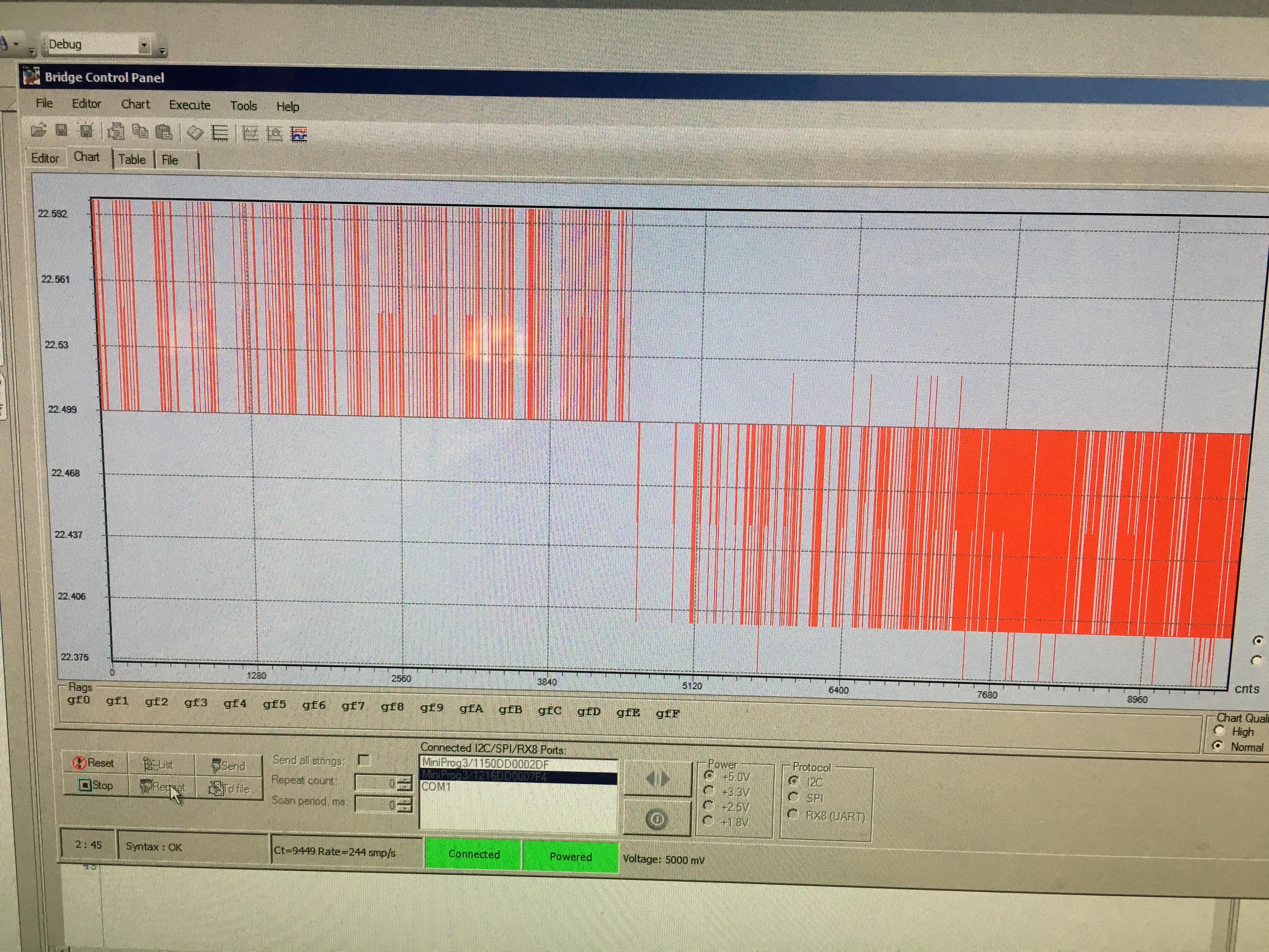
In the next test I use a Fluke Thermocouple to verify that the TMP036 is reading the correct temperature. You can see that when I put the thermocouple right on the sensor it reads 23.4 degrees C. I then turned the camera towards the screen and took a picture of the plot. In that plot you can see the temperature bouncing around 22.5. The bounce is +- 1 count (literally noise) of the ADC . I am not sure what the cause of the 0.9 degree difference between the Fluke and the TMP036, it could be several things including the accuracy of the TMP036, the accuracy of the Fluke, the accuracy of the PSoC4 ADC, where I am measuring, etc. But less than a degree really doesn’t matter to me.

In the last test I make a graph of the temperature while I am grabbing the TMP036 which causes the temperature to rise. After a bit of time I let go of the sensor and you can see the temperature fall.

At this point it looks like the bootloader is working and that the PSoC 4 firmware is working. In the next post I will talk about the overall server software architecture.
Index
Description
The Creek: IOT for the Elkhorn Creek
Introduction
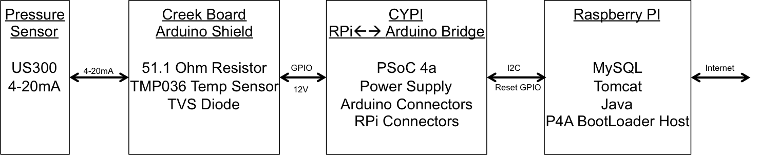
The Creek: Solution Architecture 1.0
Overall architecture
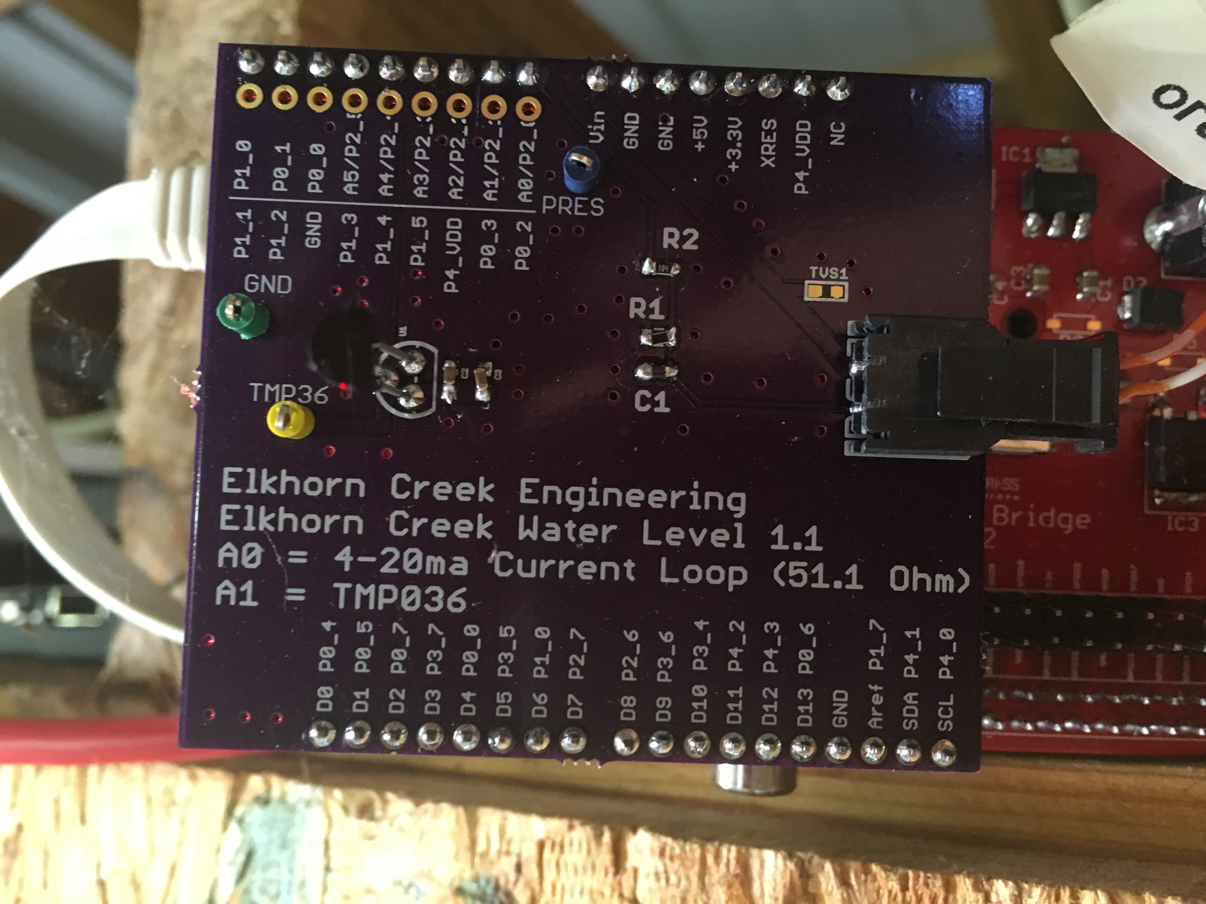
The Creek: Creek Board 1.1
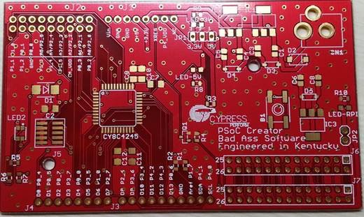
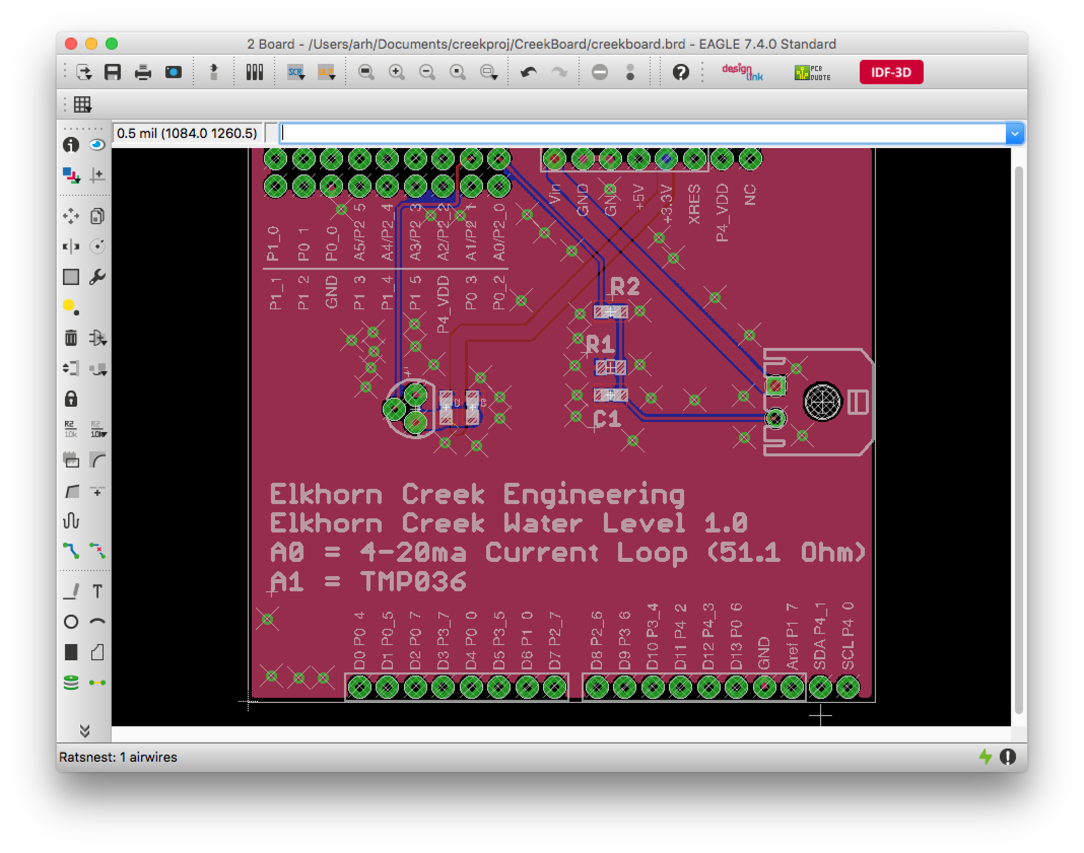
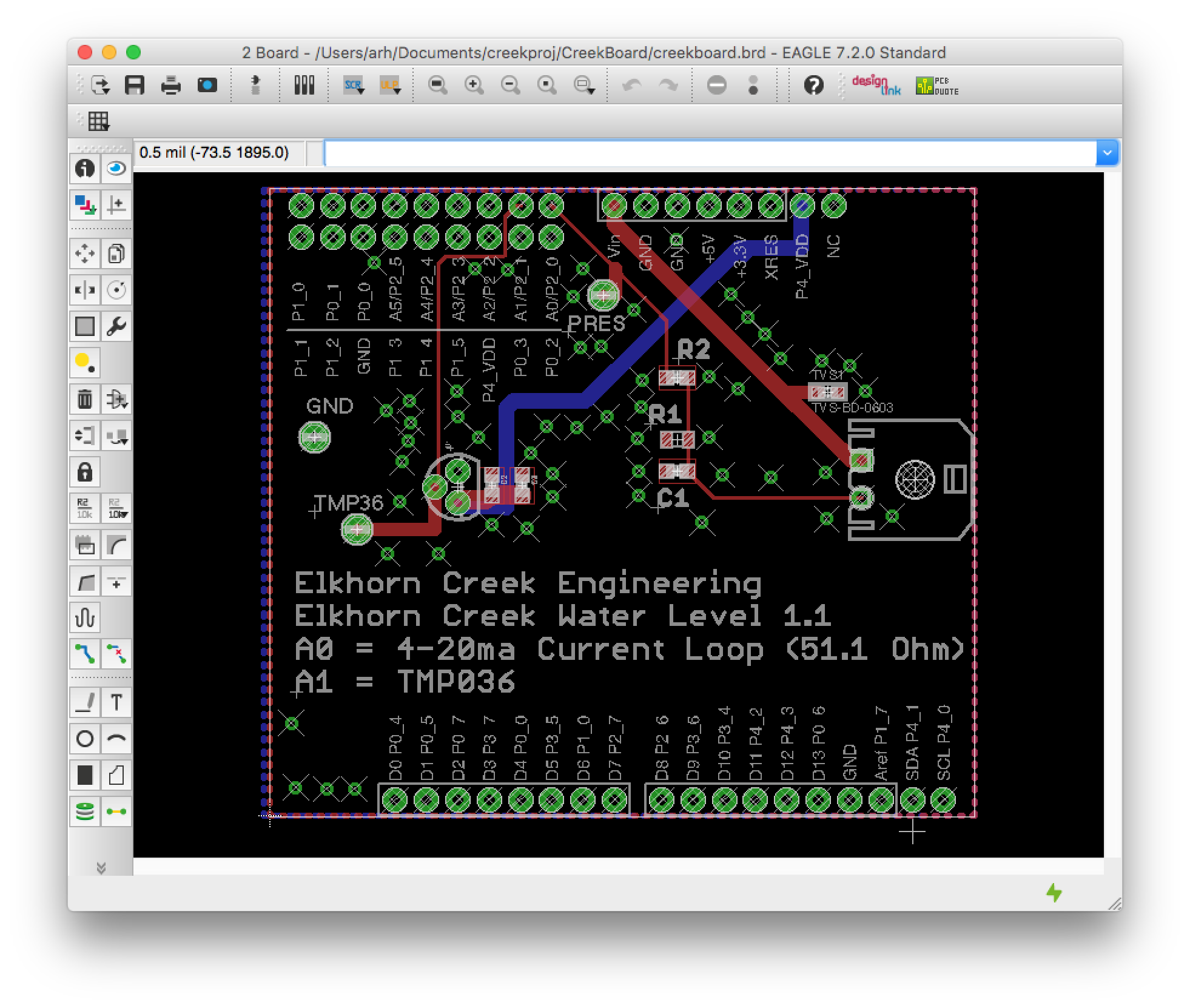
Eagle layout of the board
The Creek: Creek Board 1.0 – RCCA
A discussion of the errors in the 1.0 board
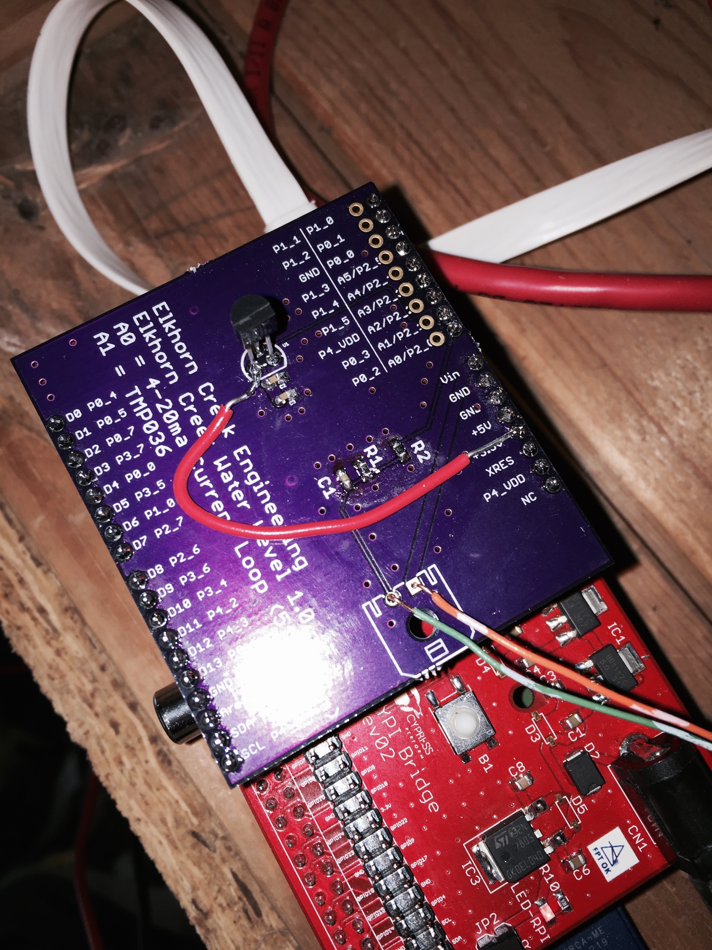
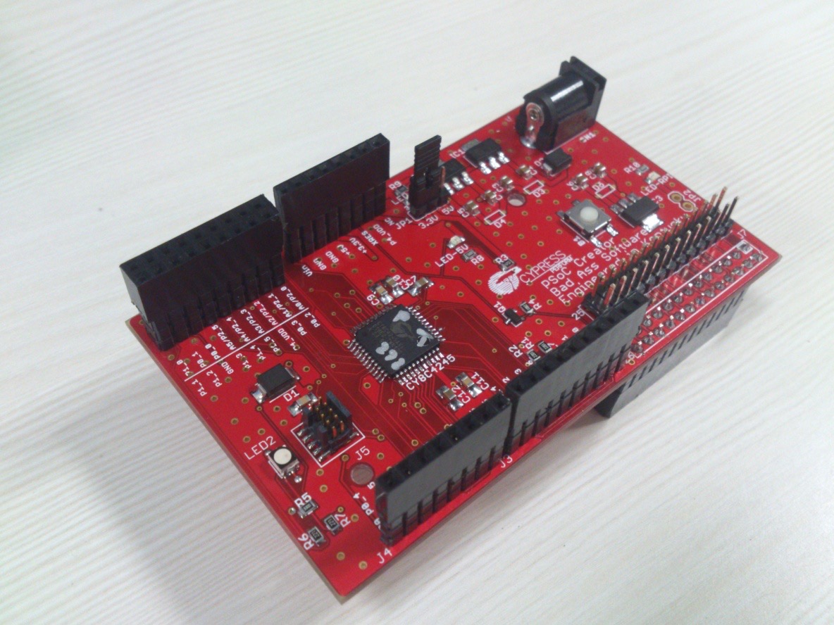
The Creek: CYPI, a Raspberry Pi to Arduino Bridge
PSoC4 <--> Raspberry Pi Bridge Board
The Creek: PSoC4 Creator Schematic and Firmware
Firmware to interface with the temperature and pressure sensors
The Creek: Testing the Firmware
Using tools to verify that the PSoC 4 Firmware is working correctly
The Creek: Testing the Bootloader
Make sure that you can load new firmware into the PSoC
The Creek: Software Architecture
All of the Raspberry Pi software connections
The Creek: Install MySql
Instruction to configure MySql
The Creek: Install Tomcat
Instruction to configure Tomcat JSP Server
The Creek: Data Collection Java (Part 1)
The Java program that reads the I2C and saves it in the database
The Creek: Data Collection Java (Part 2)
The Java program that reads the I2C and saves it in the database
The Creek: Create the Chart with JFreeChart
Using open source Java charting software to create plots of the Creek Depth
The Creek: Flood Event Data Processor
A batch program to create analyze the database and create a table of flood events
The Creek: Flood Event Web Page
A batch program to create the flood event web page
The Creek: Creek Server 1.1
Updates to all of the back off server programs to integrate charts
The Creek: JSP Web Page for www.elkhorn-creek.org
The JSP program to make the table and display the website
The Creek: Raspberry Pi Clock Stretching
Sorting out a bug in the system having to do with the Broadcomm Raspberry Pi Master not functioning well with clock stretching
The Creek: Creek Server 1.2
Caching the web pages to make them faster