A New Logo Design Contest for IoT Expert (Part 2)

You might have noticed that today the IoT Expert website looks completely new.  And, you would be right.  The whole thing has been re-done.  Why?  There are a lot of reasons, but the bottom line is that I changed my mind.  When Yakob Dedi posted his original design to the 99designs contest I immediately thought, “Wow, that is the winner!”  Then when I sent the design around, one of my good friends said that it was obviously the winner and I should stop wasting time with the others.  But, for several reasons, I ended up going with the other design.

But, I regretted the decision.  And every day that went by, it ate at me.  One of the marketing people that I work with originally said the Yakob “IoT Expert” logo was the only choice from the contest that was iconic.  This comment kept ringing in my brain.  Finally I contacted Yakob (aka AnnSir on 99designs) , bought the logo and started the process of switching.  And now, I am much much happier for it.

IoT Expert T-Shirt

It turns out that the switch was not that easy because the WordPress template that I was using was not very compatible with the redesigned logo.  Then, we descended into the pits of hell trying to find a good template starting point.  Yakob looked at 100’s of different designs.  He selected about a dozen that we went through the merits and problems of.  Finally, we picked a template that seemed to provide all of the features we needed.  The WordPress world has a frightening amount of open-source, freemium and paid developers and it is a pain to sort the wheat from the chaff.  It is absolutely huckster-central.

As we worked through the new design, Yakob suggested that I move to icons for the menus.  When I saw his designs I was convinced.

I hope you like the redesign.  Send me email, tweet me or make a comment.


A New Logo Design Contest for IoT Expert (Part 1)

IoT Expert Logo Design Contest

When I created this blog, I looked around at a bunch of different websites.  After seeing what was out there, I bought a fairly plain WordPress theme, put it online, then started typing blogs.  This situation has been OK, but not ideal.  I realized last fall that I needed to do better.  But what?  I didn’t really know, nor have time to think about it.  Then in December, my friend John Turbek, sent me an email invitation to participate in a logo design contest for his boutique farm Fertile Pastures.

He was running a logo contest using a company called 99designs.com.  This company is associated with a bunch (like 100,000) of free lance designers.  You can create a design contest by describing what kind of things you like and what you are trying to do.  Then designers from all over the world submit their ideas.  You can refine the designs as part of a 2 stage design contest.  At the end you pick a winner, the designer gets paid, and you end up with a copyright for your new logo as well as the artifacts from the contest.

I thought that this would be an easy way to get what I needed for this website.  Turns out, I got what I needed, but it wasn’t easy.  The 99designs website works very well, but it was incredibly time consuming to look a the 724 designs that were submitted and rank/rate them and their creators.  Apparently, IoT is an interesting subject (who knew?) and I had an abnormally large number of designers and submission for my contest.  There were a bunch of really cool ideas and interesting people.

First, the winner is Ceasar Cuervo (not Jose).  Here is a link to his website. which has a bunch of really cool examples of his designs.  Here is his winning design:

I agonized for several days about the end result for the logo design contest as there where three other designers who stood out.  I was sorry not to choose them because they seemed to capable and creative.  I would recommend any one of them.

The best of the finalists was Ann Sir.  He has a super cool website with his portfolio.  I was very close to choosing this design as the winner because I thought that in many ways it the most creative.  Here is his design, which even now,  I am sad that I didn’t choose.

Ann Sir logo design contest submission

The next person is Ivek_design.  Ivo lives in Croatia and has won a bunch of these contests.  I thought that his submission to the new logo design contest was really creative.  Moreover, he “gets it” and I found him to be very responsive an intelligent.  Here is the Ivek Design:

Ivek Design logo design contest submission

The final person who I really liked is Kaylee CK.  Ms. Kalee CK was by far the most prolific of the designers who submitted to the new logo design contest.  She is super responsive and was the source of many many ideas that I thought were clever.  She is also a “go-getter” type and has won a bunch of these contests.  Here is one of her many designs which I also think is very clever.

Kaylee CK logo design contest submission

In an upcoming post, Ill talk about the whole process that I followed to get this chosen and deployed.

IOT Expert 2016 Year in Review and 2017 Goals

Summary

This week as I looked back on 2016, I decided to evaluate where I have been with my project www.iotexpert.com and what the future should look like.

I started this website in the fall of 2014 when I was on vacation from Cypress.  In that first 4 months I made 14 posts, which, at the time, I thought was an OK start even though my original goal was to post 2x per week.  On December 7, 2014 I went back to work full time at Cypress and I let things get out of control in my personal life.  One signal of that problem was only two posts during 2015.  At the end of January 2016, I decided that my only goal for this site would be to post once per week for the  rest of the year.  I far exceeded that goal by completing 76 posts.  During 2016, I also started the @askiotexpert twitter feed as well as becoming the first or second google hit for “iot expert” and “iotexpert”.  In terms of opportunity for my website, the best thing to happen was the acquisition of the Broadcomm IoT group by Cypress.  This gave me easy access to WiFi, Bluetooth and Zigbee.  All three of these technologies will play a big role in the coming year.

All-in-all I am pretty happy with the results. But, I think that I have learned quite a bit that will improve your experience for the future.

2016 Data

Topic # Posts Comment
The Creek 21 IOT-ifying the Elkhorn Creek with PSoC
Pinball 19 PSoC component projects, board design etc for the non-profit Newton's Attic
PSoC 4000s 11 Smart IO, BLE and CapSense projects for the PSoC 4000s series
CY8CKIT021 8 A bunch of PSoC projects for the new teaching development kit
Electronica 2016 5 Building up demo projects for Electronica
Personal Cloud Services 4 GIT,MQTT,AMQP,MAC Server, etc.
Maker Faire 3 My experience in Rome,New York, and the Bay Area Maker Faire's
WICED 2 The beginnings of a new series on IoT using Cypress WICED WiFi
Embedded World 1 My presentation from Embedded World
Eagle PCB 1 The most popular post of the year with rules for designing PCBs
Qinsi 1 The second most popular post of the year with temperature profiles from my Qinsi QS-5100 reflow oven

I made good progress with the number of page views and unique users through the year.  Though, it is clear that something happened in September and October that I should look at.

2016 Areas for Improvement

There are three areas that I feel that I should improve on for next year.

  1. Gaps in posts:  There were a couple of stretches where there was a multi-week gap between posts.  I need to make sure and work ahead so that I always have material on the hook to fill in the gaps that occur because of my travel.
  2. Quality:  I need to be continuously vigilant about my writing, grammar, spelling etc.
  3. Searching:  In order to make things easier to find by onsite and offsite (google) search I need to be very deliberate about using titles, tags and meta data.

2017 Goals

For 2017 my goals fall into three broad categories.  First, I want to continue creating (hopefully) interesting, high-quality IOT engineering content.  To that end I would like to:

  1. Achieve 2x/week posts and hit 104 posts for the year.
  2. Create a new video series and post 12 videos.

In addition to the new content, I would like to improve the accessibility of my website by

  1. Deploying a mailing list
  2. Automatically connecting to Twitter
  3. Automatically connecting to Facebook
  4. Developing a Linked-In strategy
  5. Fixing my release process to use best practices for all meta-data

such that I achieve

  1. 10x User Traffic
  2. 10x Twitter followers on @askiotexpert
  3. 10 Google keywords where www.iotexpert.com is a first page hit

Lastly, I want to update and deploy a new brand for iotexpert including logo’s, web page headers, Facebook covers, etc.

This year should be interesting.

Alan

Qinsi-QS5100 Sn63Pb37 Solder Profile

About 2 years ago, I bought a Qinsi QS5100 reflow oven from China via Amazon.com.  My decision was based almost completely on the nice youtube video that Ian Lesnet from Dangerous Prototypes posted about his results.  After I got the oven, I successfully built a series of Physics Lab boards with it.  Then one day about a year ago, I got two boards in a row with horrible results which I attributed to the temperature profile.  A few weeks later, I dug around on the internet and decided to change to the Lesnet profile and things seemed to be working again.

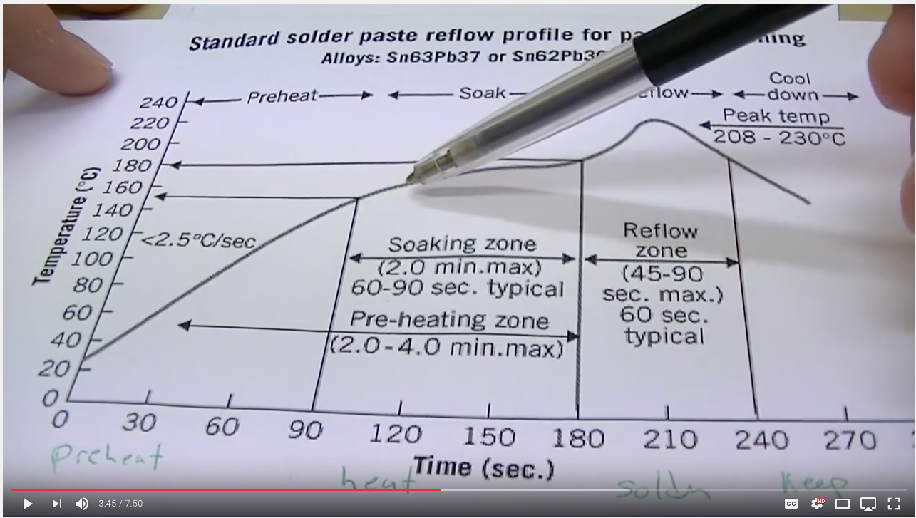
I have always had this bouncing around in the back of my head as a potential problem because I wasn’t SURE about the source of my original problem.  And, I don’t really believe in magic, but I didn’t have time to pursue a root cause.  As I have had a little bit of time the last few days, I decided to dig in.  First, I found the data sheet for the Kester solder paste that I have been using.  Here is scan of the printout of a blown up section from the datasheet with my handwritten notes from the Lesnet video (which I incorrectly denote as Sparkfun)

screen-shot-2016-11-27-at-8-41-17-am

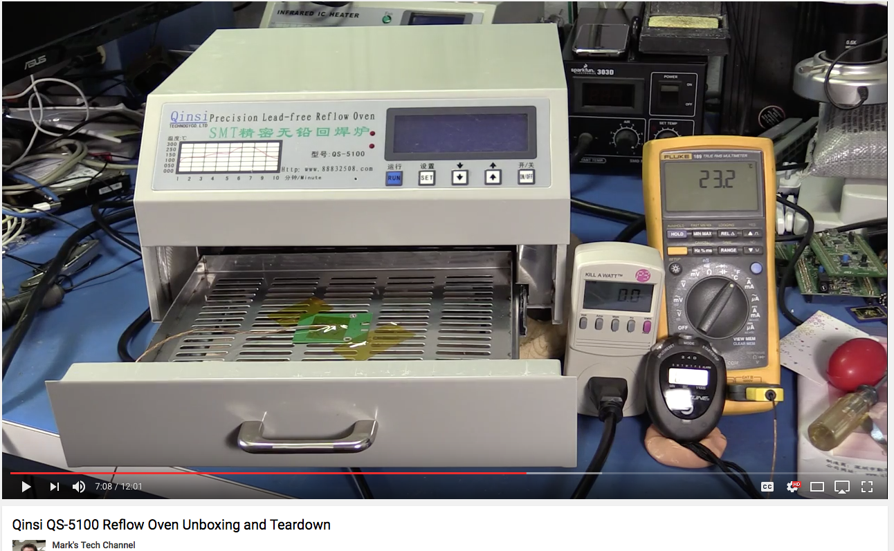
In fact in the video Mr. Lesnet shows a screenshot of a solder profile which is similar to the Kester data sheet.  I wondered why he didnt use that profile?

screen-shot-2016-11-27-at-8-57-22-am

I had switched to using the Lesnet profile and was having consistently good results.  However, yesterday I decided that I wanted to compare that program with reality.  I found at least a couple of places on the internet where a comparison of the actual temperature and the programmed temperature were made with a Fluke & Thermocouple.

screen-shot-2016-11-27-at-9-00-03-amscreen-shot-2016-11-27-at-9-01-36-am

In the past I used the Fluke/Thermocouple method as well, but I found it difficult to compare a time based profile with instantaneous readings from the Fluke.  Moreover the numbers that you can read from the Kester data sheet don’t seem to match what you can enter into the QS-5100.  So, what in the world is the oven doing?

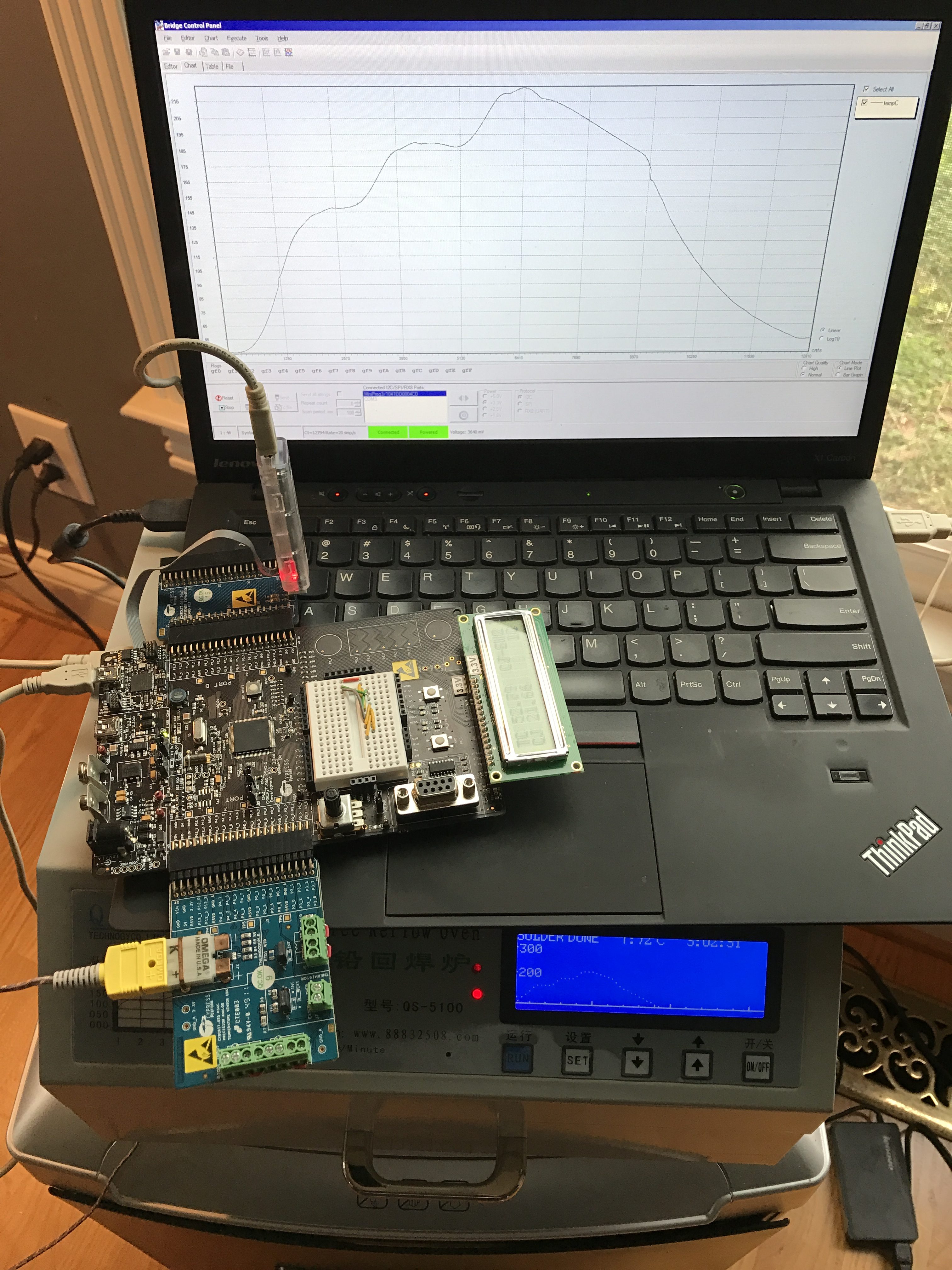
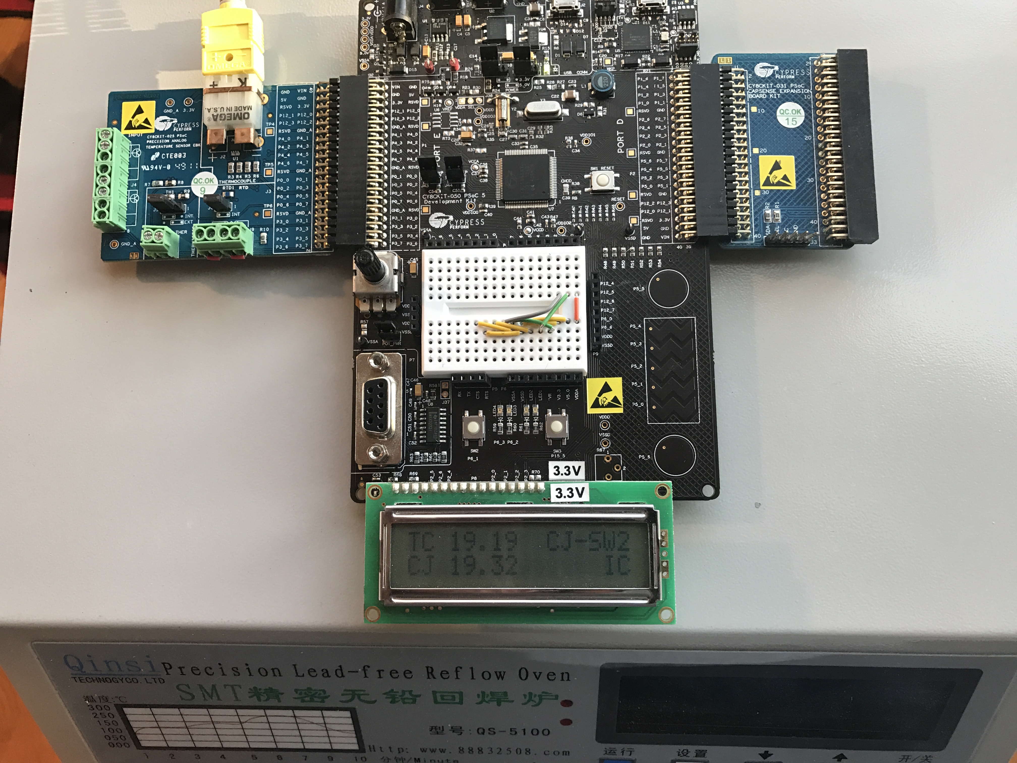
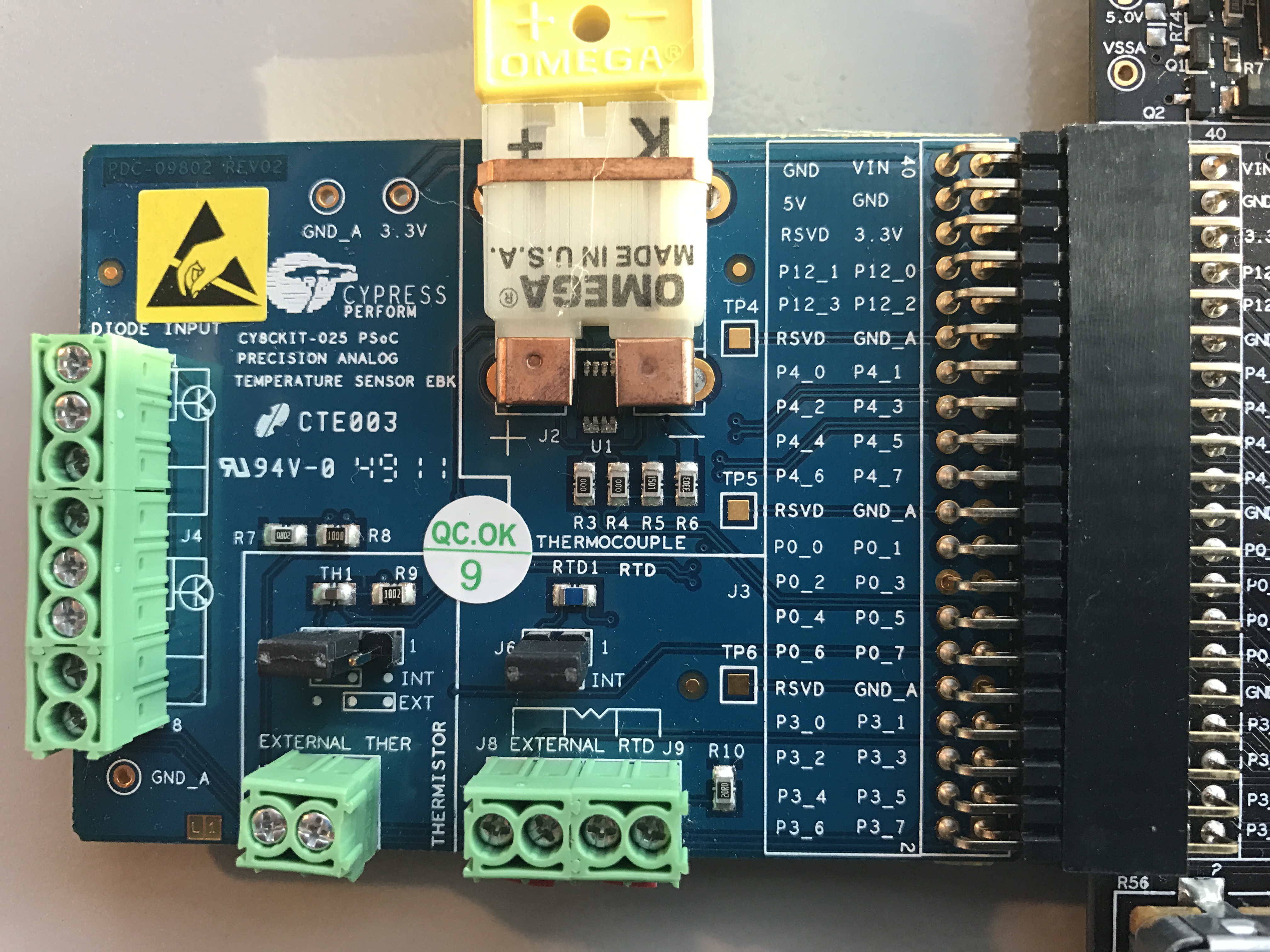
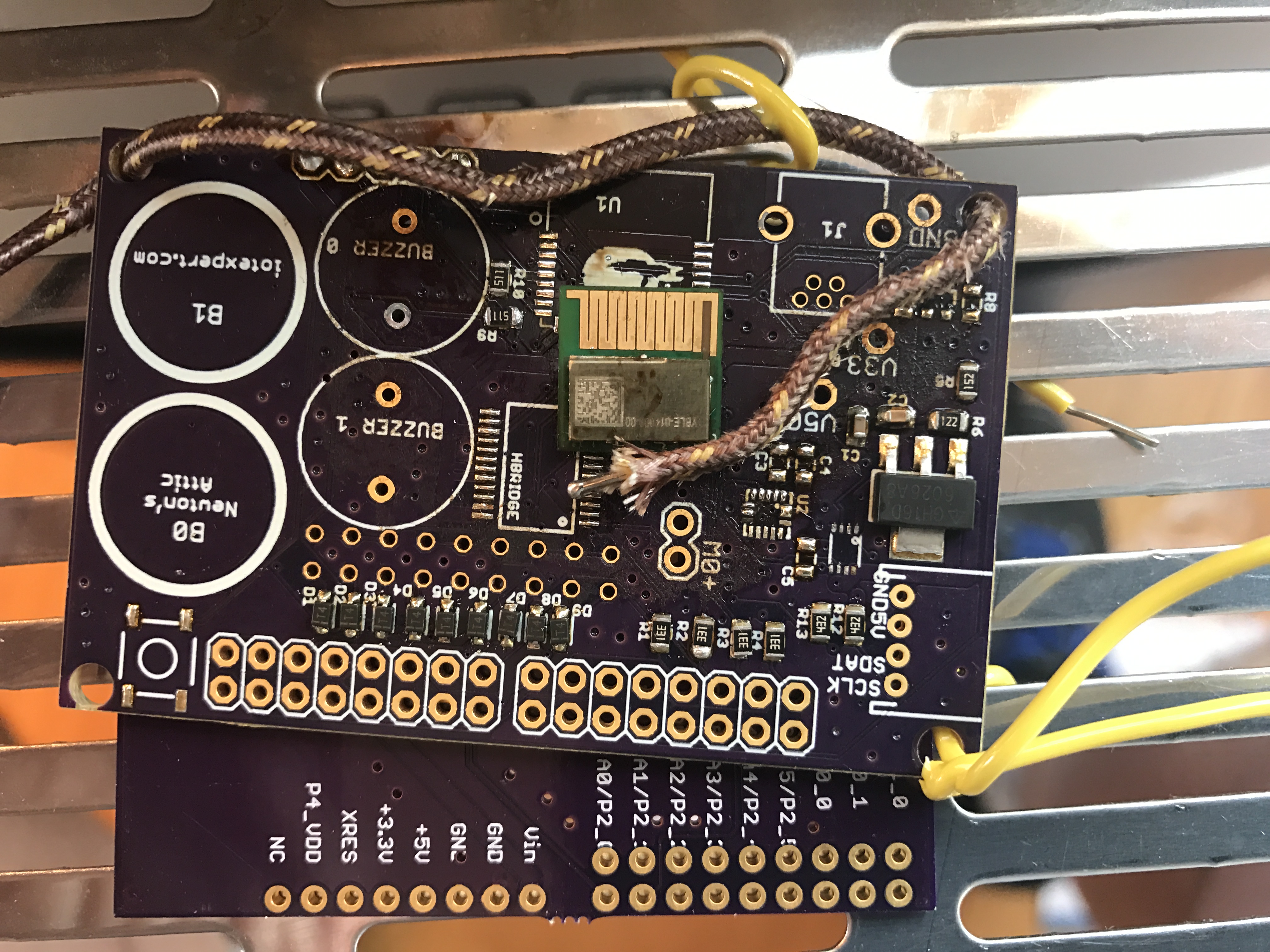
What I really wanted was to capture the data in realtime so that I could plot and analyze what the oven was doing.  To do this I used CY8CKIT-025 Precision Temperature Sensor Expansion Board attached to a PSoC5LP CY8CKIT-050 connected to the Bridge Control Panel to capture the actual PCB temperature into an excel file.  The CY8CKIT-025 has a K-Type thermocouple, a DS600 for cold junction compensation, a thermistor, an RTD and a temperature diode.  When paired with the 20-bit ADC in the PSoC5LP you are able to demonstrate a bunch of different methods for measuring temperature.  I used the example project that came with the kit with one modification, the addition of an “EZI2C”.   By putting in an EZI2C I was able to use the Bridge Control Panel to measure the temperature every 100ms and record that data to a file for analysis.  Here are several pictures of the setup:

img_3386

The board on the right side of the CY8CKIT-050 has a little header where you can plug in a miniprog-3 to use as an USB->I2C bridge

img_3390

img_3388

In the picture below, the PCB has been through about 15 reflows (which is why it looks so crappy).  The yellow wires are holding the board and the thermocouple wire in place.

img_3392

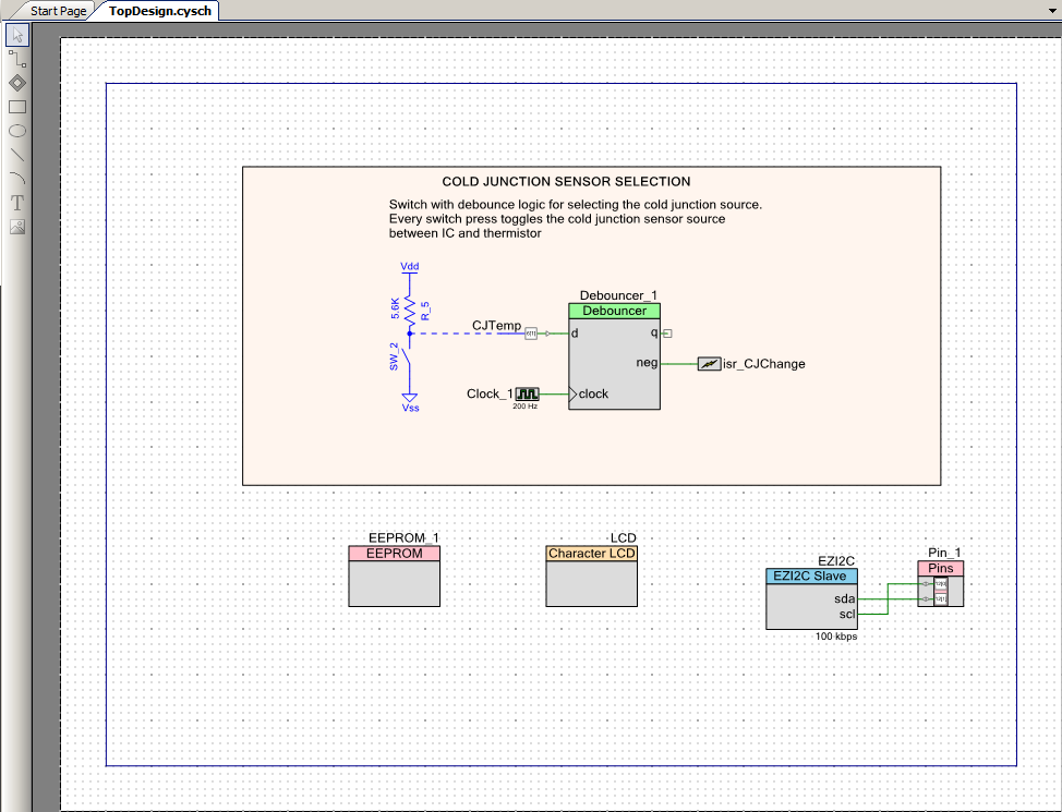
The modification that I made to the Cy8CKIT-025 kit example project were

  • Add the EZI2C Component

screen-shot-2016-11-27-at-10-26-23-am

  • Make a floating point buffer and attach it to the I2C

screen-shot-2016-11-27-at-10-27-20-am

  • Save the thermocouple data into the floating point buffer

screen-shot-2016-11-27-at-10-27-34-am

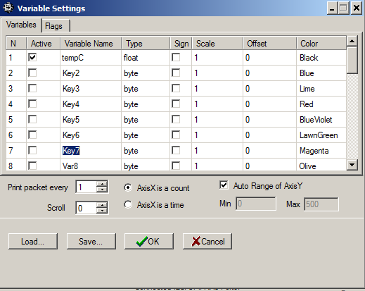
Once that was done, I can start the Bridge Control Panel and set it up to automatically read from the I2C by first setting up the variable tempC, setting up the read and then setting up the 100ms repeat.

screen-shot-2016-11-27-at-10-50-45-am

bcp

Now, I can run the whole thing and view the chart.

bcpgraph

All of the temperature measurement is setup, so I can take some real data.  First I look for repeatability by running a couple of heat cycles.  The oven seems to act the same way every time here is an overlay of the 12th and 13th run.  (bad Alan… label your axis)

data-overlay

And finally we are ready to do a little bit of analysis.  Here is an annotated plot of Run12 which was done with the Lesnet profile:

  • Preheat 150 degrees 60 seconds
  • Heat 180 degrees 58 seconds
  • Solder 210 30 seconds
  • Keep 180 degrees
  • Cool 150 degrees

Based on the graph you can see that the oven seems to have 4 modes:

  1. Heat
  2. Hold
  3. Cool
  4. Cool with fan

In the graph below:

  •  The heater turns on to drive the temperature to the preheat phase (mode 1).  The oven heater appears to be able to raise the temperature linearly at about 1.6 degrees C per second.  Once it gets to the preheat temperature, it try’s to hold the temperature at about 145 degrees for 58 seconds (151-93) in mode 2.  Looking at the graph this section isn’t very flat, so I wonder if there is really a 5th mode?
  • The oven turns on the heater and the temperature ramps up to about 186 degrees (mode 1), which it then attempts to hold for about 60 seconds (mode 2)
  • Then the oven turns on the heater and raises the temperature to about 219 degree (mode 1), which it then holds for about 30 seconds (mode 2)
  • Then the oven lets the temperature drop naturally until it reaches about 180 degrees (mode 3)
  • Then the oven turns on the fans and drives the temperature in a steeper line down to 150 degrees (mode 4)
  • Then the oven turns off the fans and lets the oven cool down (mode 3)

analysis

As far as accuracy goes, the time measurement seems pretty good (one website bitched about this).  With regards to temperature it appears that the oven is a bit low during the preheat phase (which is also not very flat) and is a bit high during the heat and solder phases.  I think that I might lower the heat/solder temperatures a little bit.. 5 degrees?

As far as matching the Kester profile goes, or the the profile on the screenshot that Mr. Lesnet showed in his video, the heat/soak phase the temperature is just a little bit high.  However, he never says that his profile is intended for Sn63Pb37 solder so maybe he was trying to achieve something else (that is what I get for making an assumption).  The profile does however, work very well for me for that solder.  So where does that leave me?

The book that came with the oven (which is obviously translated from Chinese into very funny English) says about the same numbers for the preheat and heat and a bit hotter for the solder.

img_3393

But interestingly, the oven does not come pre-programmed that way for any of the default profiles:

img_3394

The book that came with the oven also has a nice chart with some properties of different alloys of solder.  On that chart it says that the melting point of Sn63Pb37 is 183 degrees. That means that the soak/preheat phase is just below the melting point of the solder.  My best guess it that the spot where the thermocouple measures the temperature-just off of the surface of the board-is actually just touch higher than the actual junction temperature which is why I think that it works.

img_3396

The next real boards that I do I think that I will run an experiment and lower the preheat temperature by 5 degrees.  Unfortunately that still leaves me with the question… why did I have bad solder joints originally?  I think that the answer is old solder paste, but I am not sure that I will ever know.

That is it. While I was looking for information I found a number of resources on the internet to be useful

Link Comment
Ian Lesnet youtube video
Marks Tech Channel teardown of QS-5100 He warns you that a wire isn't connected properly
Kester Datasheet Graph profile on 2nd page of document
Reflow 7 youtube video A sweep of the temperature measured with a multi-meter
Dangerous Prototype Forum discussion a few solder profiles + some proposed modifications
MakeICT scan of QS-5100 manual Just a scan of the manual
An EEVBlog Forum discussion of the QS-5100 A bit of chatter
Despectus blog teardown of QS-5100 A modification of the placement of the thermocouple
Labitat wiki A few different reflow profiles & instructions

Electronica 2016 – The WICED Server

The last three days at Electronica I have been showing people how to build the Robot ARM Controller.  In previous posts I talked about the process for the Servo Motor controller and the CapSense user interface.

image009

In this post I am going to focus on the TCP/IP Server running on the Cypress WICED board.  Remember that this board performs two functions

  1. An I2C Master which writes data to the PSoC Servo Motor Controller
  2. A TCP/IP Server listening on TCP Port 40508.  The command format of the TCP/IP Packet is a 2-digit ASCII coded hex number representing the position of motor 1 followed by a 2-digit ASCII coded hex number for motor 2 e.g 3240 takes motor 1 to 0x32 aka 50% and 0x40 aka 64% for motor 2

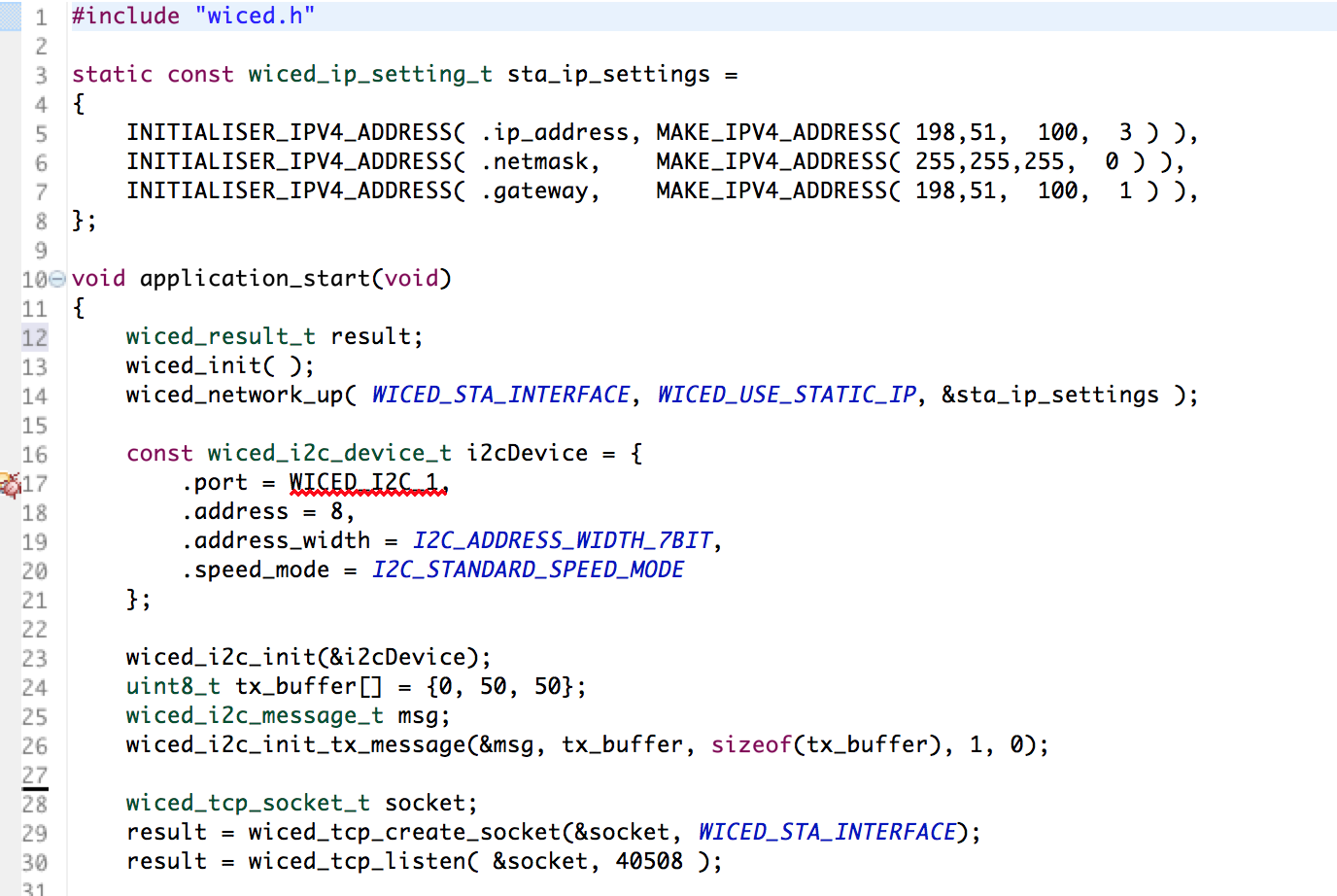
The first section of code (lines 11-14) gets things going by starting WICED and attaching to the network.  The next section (lines 16-26) sets up the I2C Master and creates a standard message buffer (called tx_buffer).  Finally on lines 28-30 creates a socket and starts listening to TCP/IP Port 40508.

screen-shot-2016-11-11-at-7-30-38-am

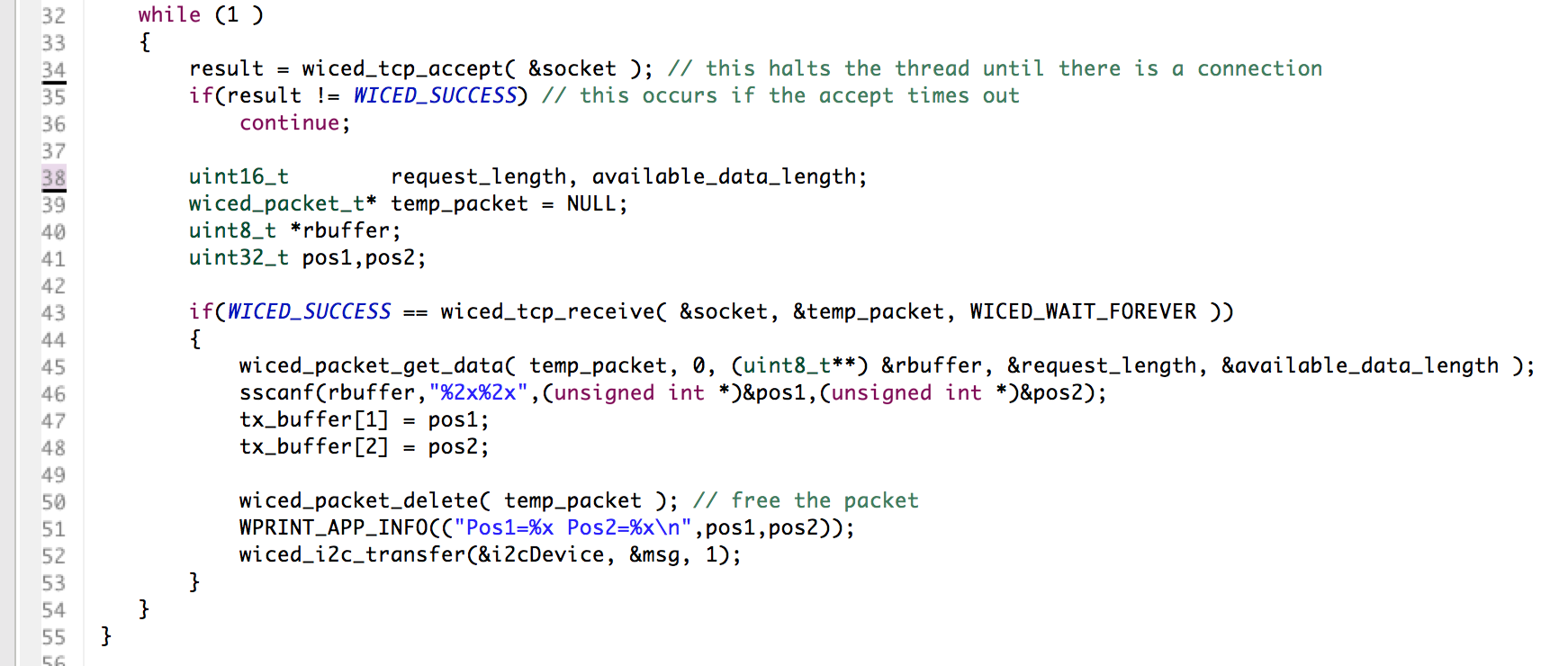
The main loop of my server starts by waiting for a valid active connection (line 34-36).  Then when it gets a valid connection it

  • Line 43: receives the data into a packet
  • Line 45: gets a pointer (rbuffer) to the data in the packet
  • Line 46: translates the ASCII data into integers
  • Line 50: frees the tcp pack
  • Line 52: sends the updated position to the PSoC via I2C

screen-shot-2016-11-11-at-7-35-08-am

All of this source code is posted to the iotexpert GitHub site at git@github.com:iotexpert/E2016RobotArm.git

Electronica 2016 – CY8CKIT-145 User Interface

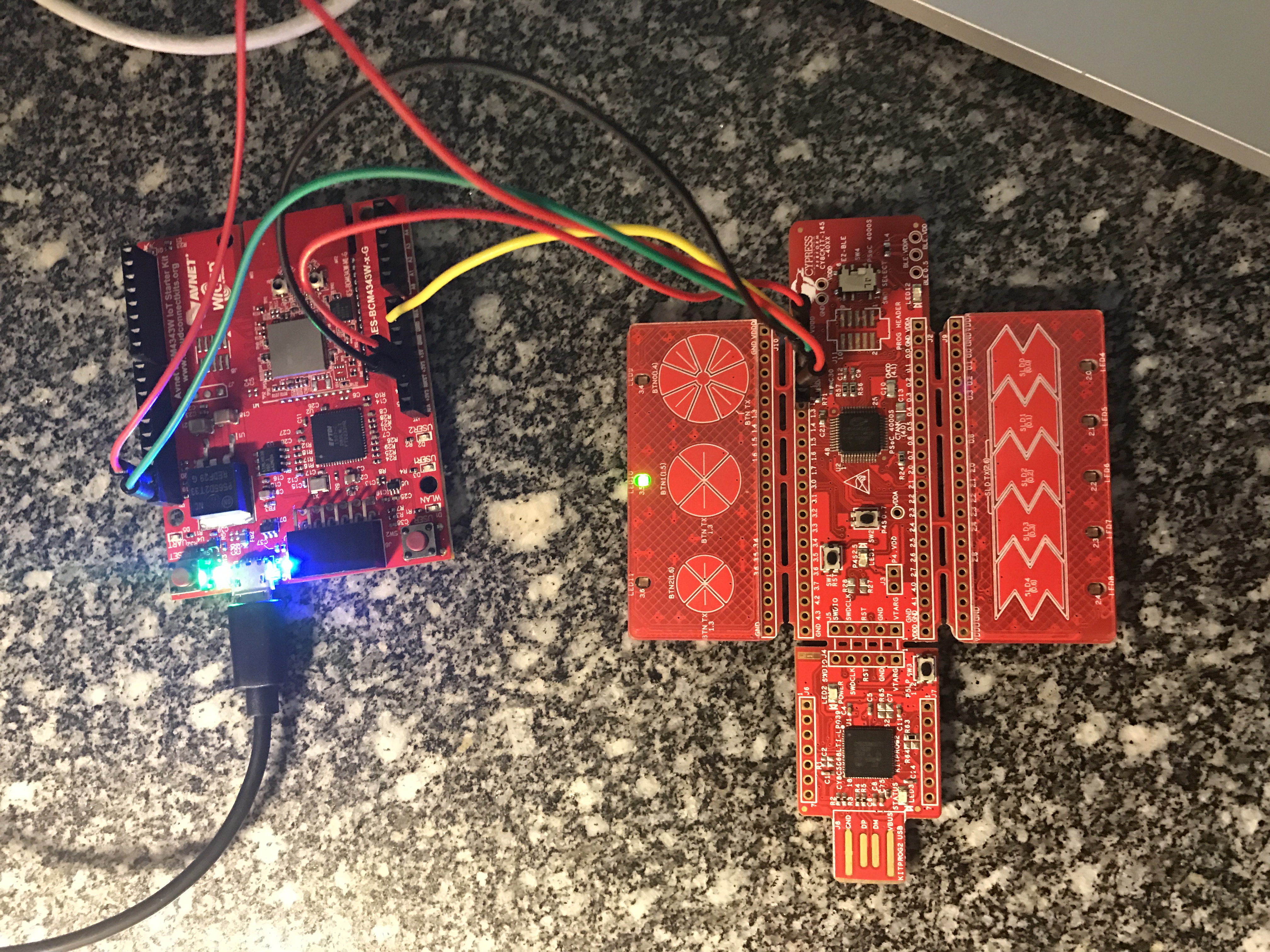
I finally made it to Munich late yesterday afternoon… then I proceeded to turn my hotel room into an electronics lab as I frantically worked to finish everything for tomorrow.  Earlier this year I wrote a whole series of posts about the PSoC4000S & CY8CKIT-145 after the Embedded World show.  We finally have volume production on the development kit and will be giving them out at the show this week.  So, I decided to use the -145 as part of the user interface for my Electronica project.  The devkit functions as the block labeled “PSoC Capsense”.  The wire between the “PSoC Capsense” and the “WICED WiFi” will be I2C (the green and red wire from the picture below)

electronica-wiced

The -145 devkit has the PSoC4000S silicon on it which has the new mutual capacitance capsense block.  On the devkit, there are three mutual cap buttons and one slider.  Here is a picture of the devkit connected to the WICED WiFi board that I am going to use:

img_3318

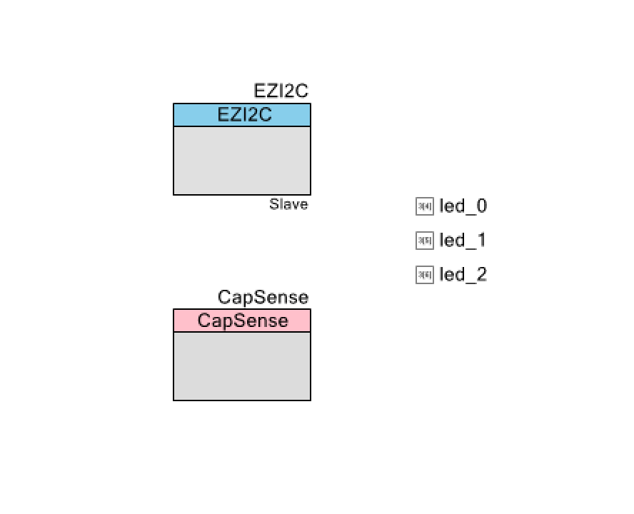
I want to make as simple of a PSoC Creator project as I can possibly do as I want to be able to easily do it live.  Here it is:

screen-shot-2016-11-07-at-10-12-23-am

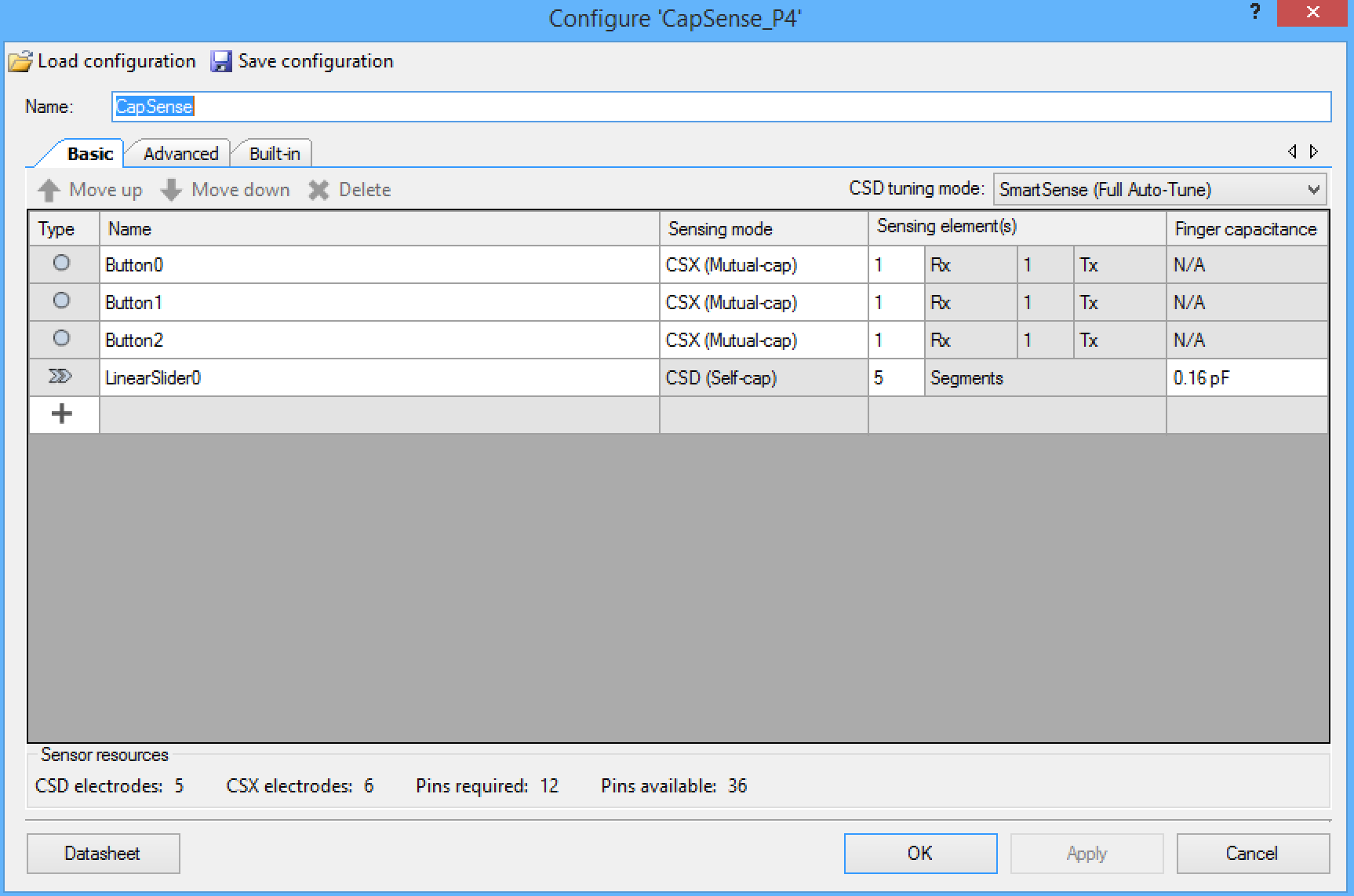
The CapSense block is configured with three mutual cap buttons and 1 self-cap slider:

screen-shot-2016-11-07-at-10-13-54-am

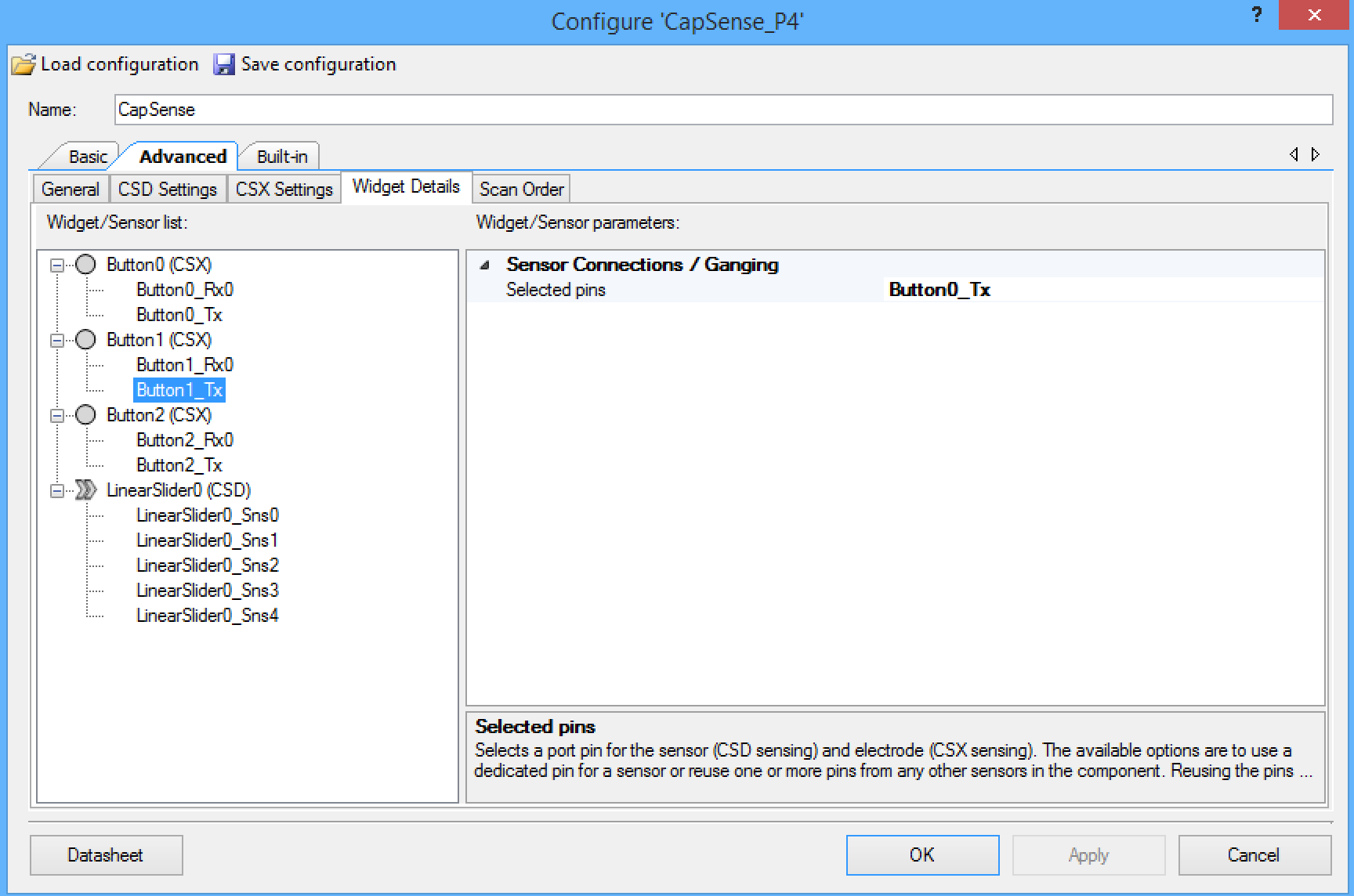
On this development board, the three mutual cap buttons share the same transmit line, so you need to configure the component that way. The screen shot below shows the configuration of the “Button1_Tx” which is set to share the “Button0_Tx”.  You need to make the same setting for “Button2_Tx”.

screen-shot-2016-11-07-at-10-15-34-am

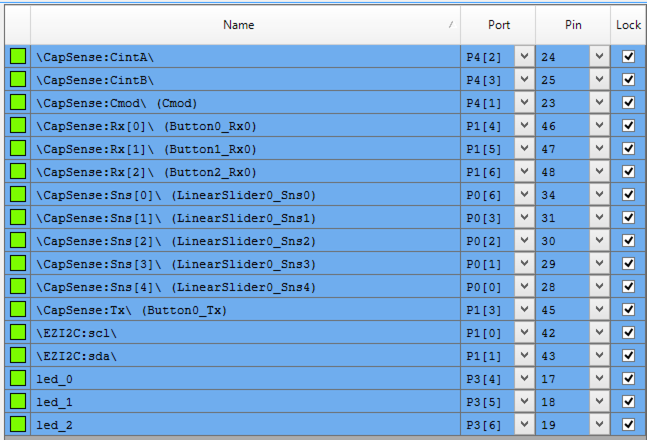
The next step is to assign all of the pins to the proper locations:

screen-shot-2016-11-07-at-10-18-10-am

Finally the smallest amount of firmware that I could think up to hold it all together.

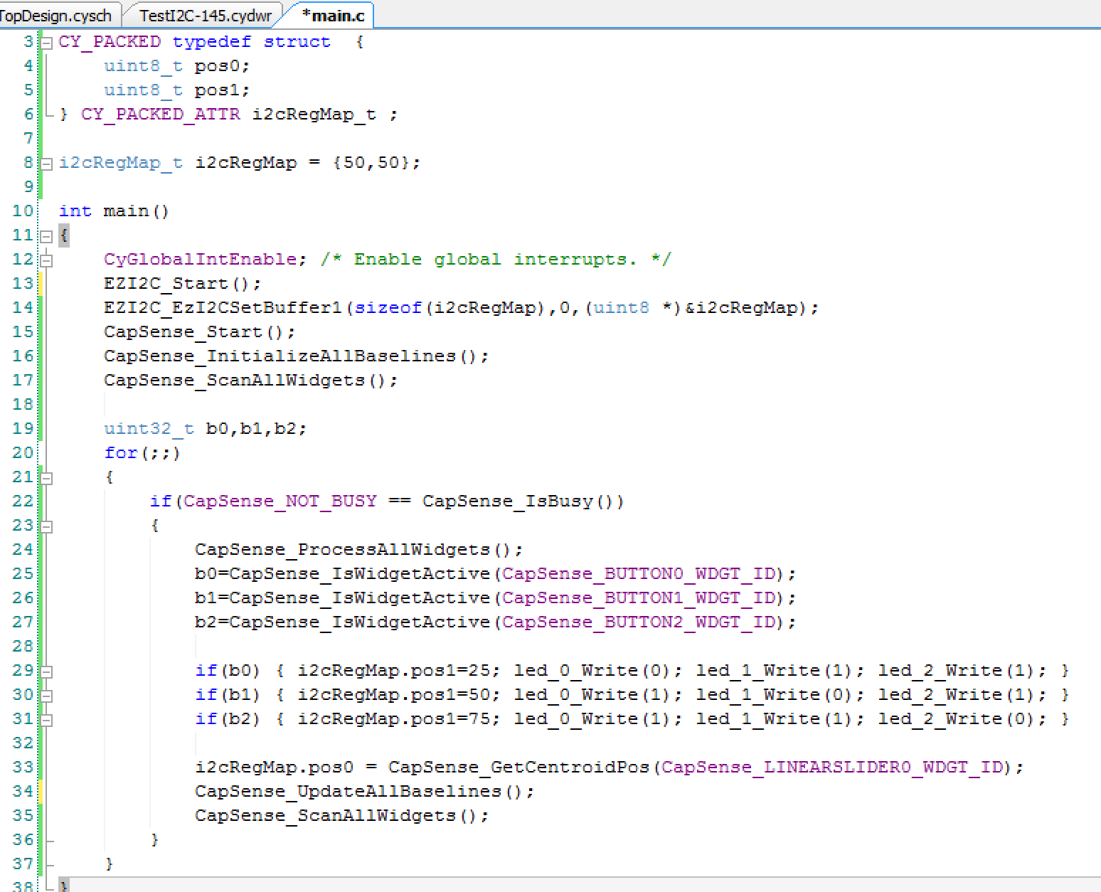
Line 3-6: define a structure that the WICED board will be able to read.  It will represent the position of two of the Servo motors.  The CY_PACKED provides the compiler appropriate key words to make the bytes be right next to each other in the RAM, i.e. not word aligned..

Line 8: initializes both positions to 50%.

Lines 12-17 get the components going

Line 22: Checks to make sure that the CapSense block is not scanning before it reads the results

Line 24: Tells the CapSense block to process the results from the previous scan

Lines 25-31: Looks at the three buttons, sets the LEDs and sets pos1 to be either 25%, 50% or 75%

Line 33: Reads the position of the slider and assigns it to “pos0”

Lines 34-35: Gets the scanning going again

screen-shot-2016-11-07-at-10-21-02-am

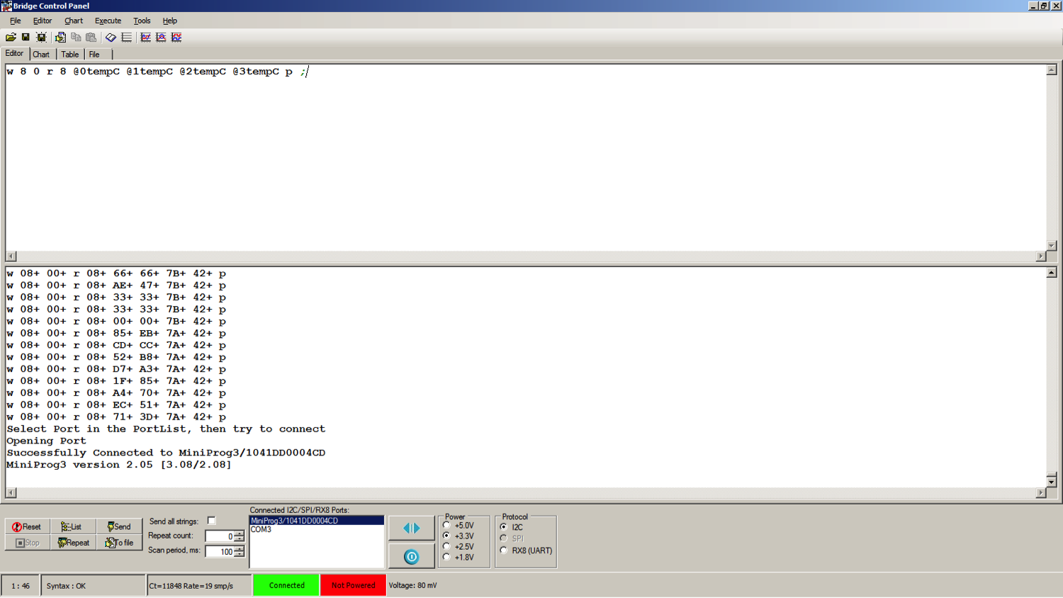
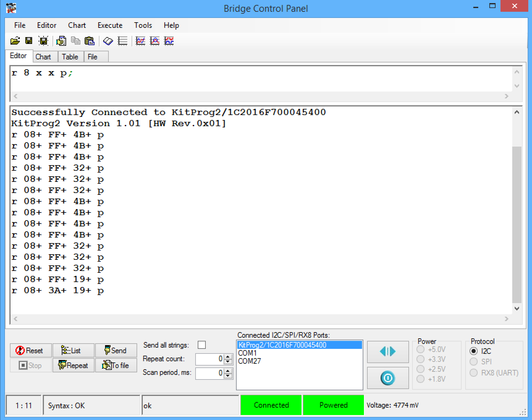
To test the system I first used the bridge control panel.  First, connect to the kitprog2.  Then I setup a read from the I2C address (0x08) which is the address of my board.  I then click repeat which runs the read command over and over again.  In the picture below you can see that I tested the three position of the button (25,50 and 75 which are also known as 0x19, 0x32 and 0x4B).  Then I tested the slider by touching it about in the middle (0x3A)

screen-shot-2016-11-07-at-10-31-52-am

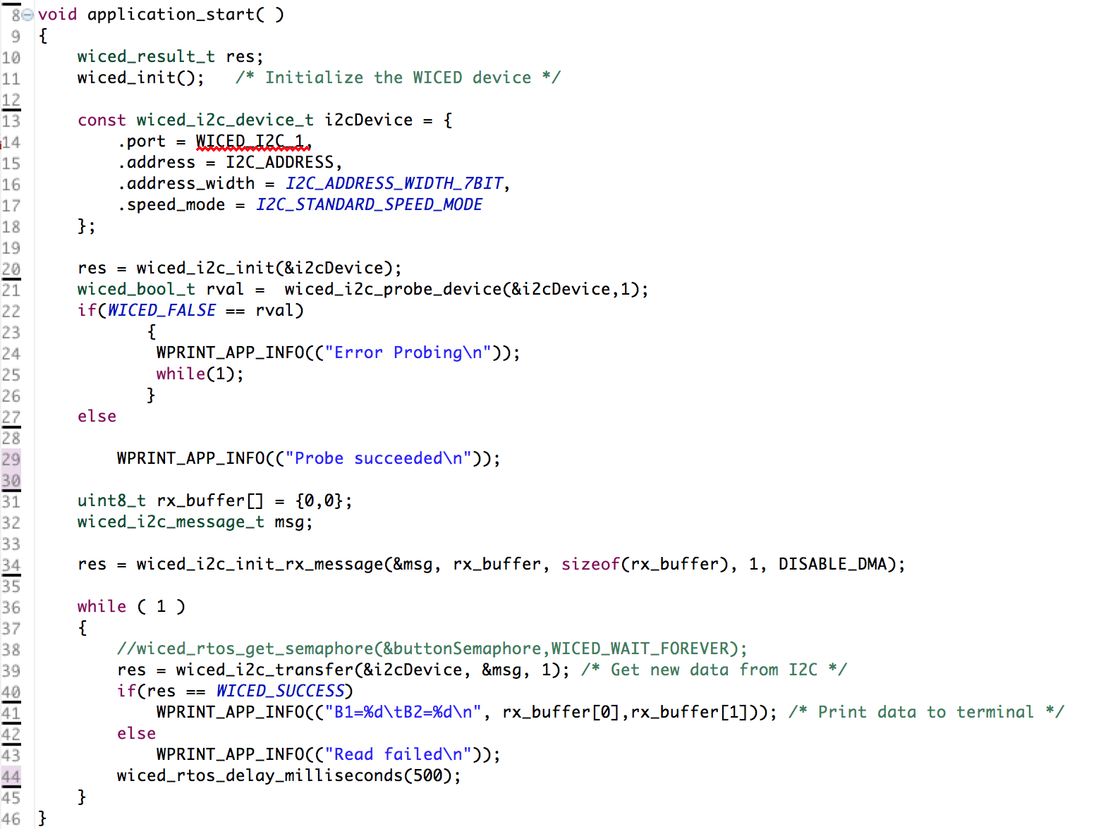
The next thing to do was make sure that the WICED devkit could read my I2C slave, so I wrote some WICED firmware to read the I2C registers every 500ms:

screen-shot-2016-11-07-at-10-55-08-am

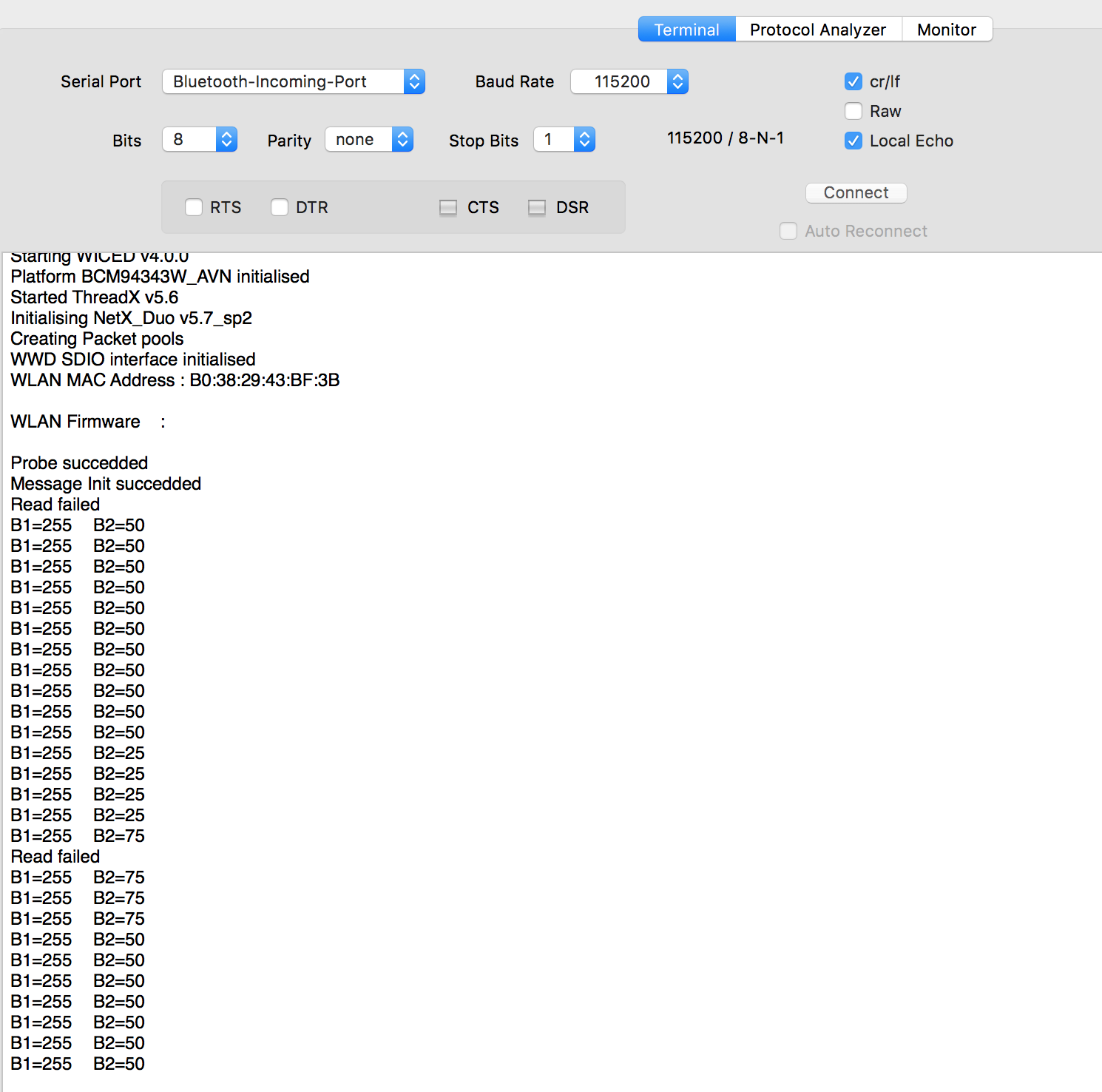
But, occasionally I  was getting a “read failed”:

screen-shot-2016-11-07-at-10-58-48-am

Last night in my sleep deprived state I was struggling like crazy to figure it out.  This morning after some sleep I realized that the WICED board that I have must not like getting its I2C clock stretched.  So, I changed the priority of the I2C interrupt on the PSoC and that fixed the problem:

screen-shot-2016-11-07-at-10-28-03-am

Keep watching here for more updates on the project.

Electronica 2016 – Servo Motor PWMs

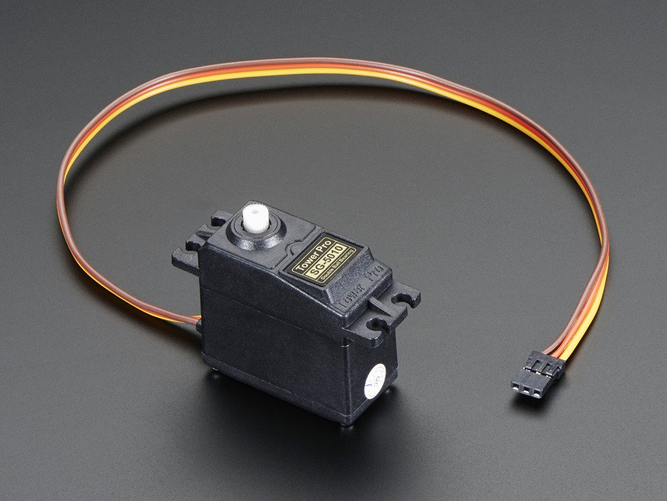
As I talked about in my previous post I am going to use a PSoC as a servo motor controller as well as a CapSense UI.  The problem is that I wanted a really easy way to plug the servo motors into the PSoC.  It seems like all of the servos have a 3 wire interface, Power, Ground and PWM.  Here is a picture that I got from Adafruit’s website.

155-01

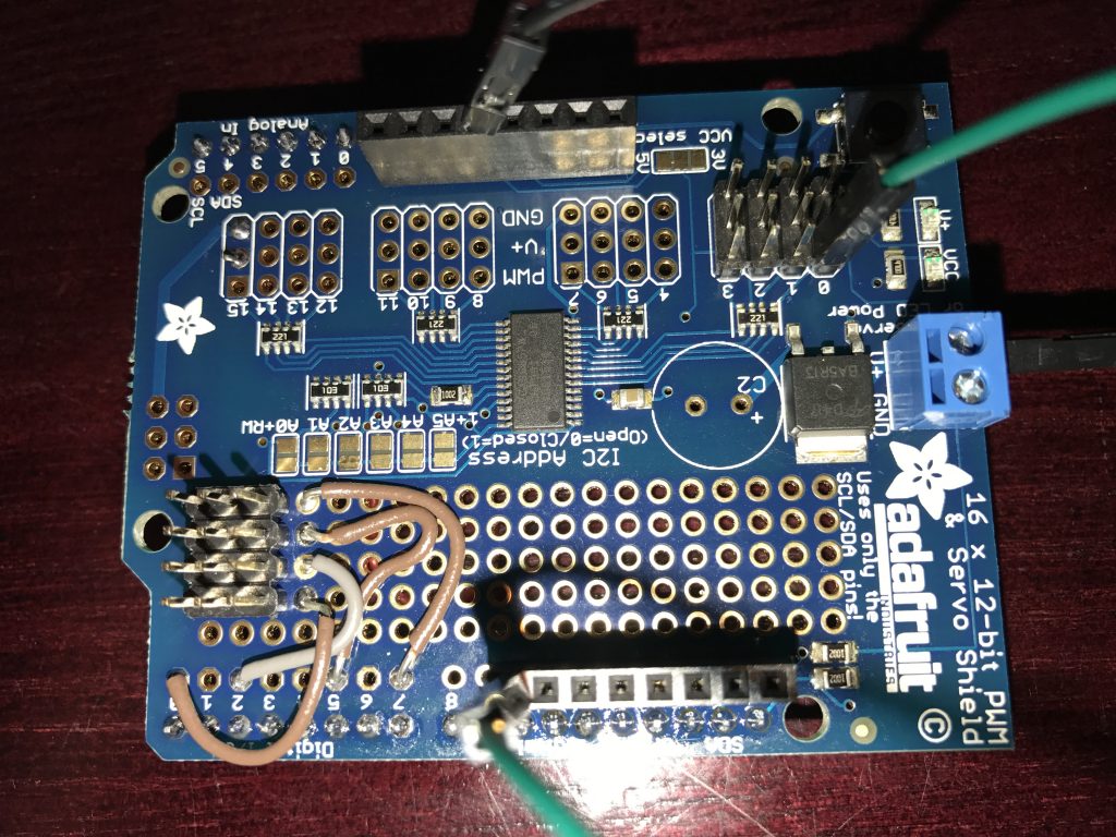
I was originally hoping that I could connect that servo directly to the PSoC, drive a ‘1’ to the power and a ‘0’ to the ground and PWM to the third input.  But, it turns out that these things suck some serious juice (100+ma?) so driving the power with the PSoC isn’t in the cards.  Given them amount of time that I had left, there was not time for a custom board, so I was in the situation of using a breadboard with wires all over the place which is ugly and a bit of a pain.  However, on Thursday I thought that I might find a “Servo Shield” and sure enough there are a number of them out there including this one which I got from Adafruit.  The problem is this shield uses a 16 channel I2C –> PWM driver from NXP.  I am not a fan of doing things with peripheral chips that PSoC can do for itself.  But, when I got the shield this morning in the mail there was a cool prototyping area on the shield.  So, I made my own header for connecting to the PSoC.  Here is the front:

img_3309

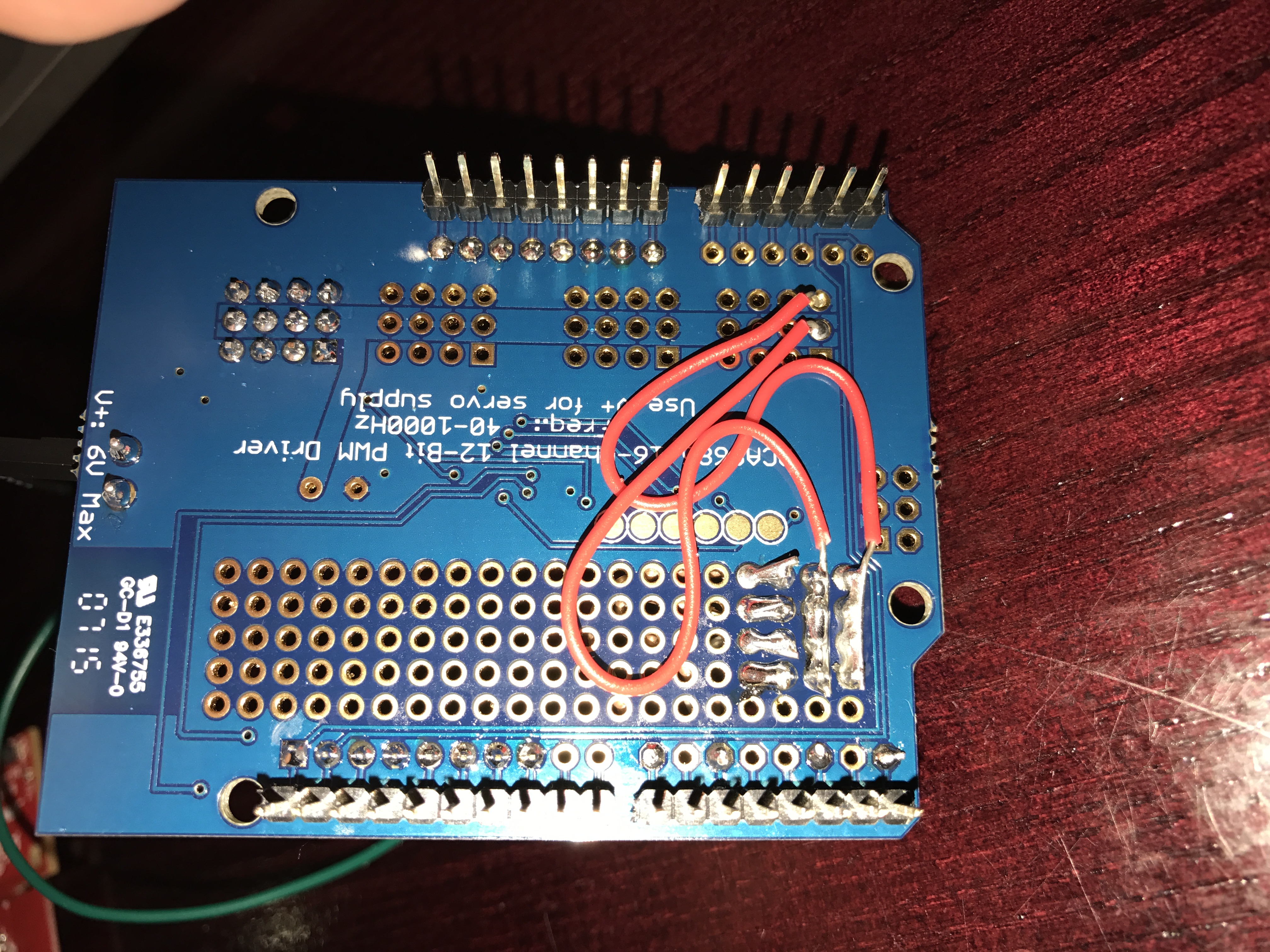
And here is the back:

img_3308

You can see that I shorted the whole row of ground together with a big blog of solder and wire.  I did the same thing with the power (the middle row).  Then I made a wire from each of the 4 PWMs pins to a good place on the PSoC (which I could drive the pins directly from one of the TCPWMs)

img_3300

The board worked great on my bench.  The only thing that I have done which is VERY questionable is that I wired the power supply for the system directly to the V5.0 aka VBUS… which I suppose will get me through the conference, but is probably a bad idea (the green wire in the top picture)

As I was flying to Detroit I thought that I might try to see how the I2C->PWM worked… so I read the data sheet for the NXP PCA9685.  It turns out that the chip is pretty cool.  You can set the output frequency by setting a divider value in one of the registers (oxFE).  The number you set is val=round(25e6/(4096*rate)) – 1.  That means for me to get 50hz to drive the motors I need to set the divider to 121.  Then to set the duty cycle each output has a 12-bit PWM where you can set “LED ON” and a “LED Off” count.  For instance to get a 25% duty cycle you can set the On to 0 and the off to 1024.

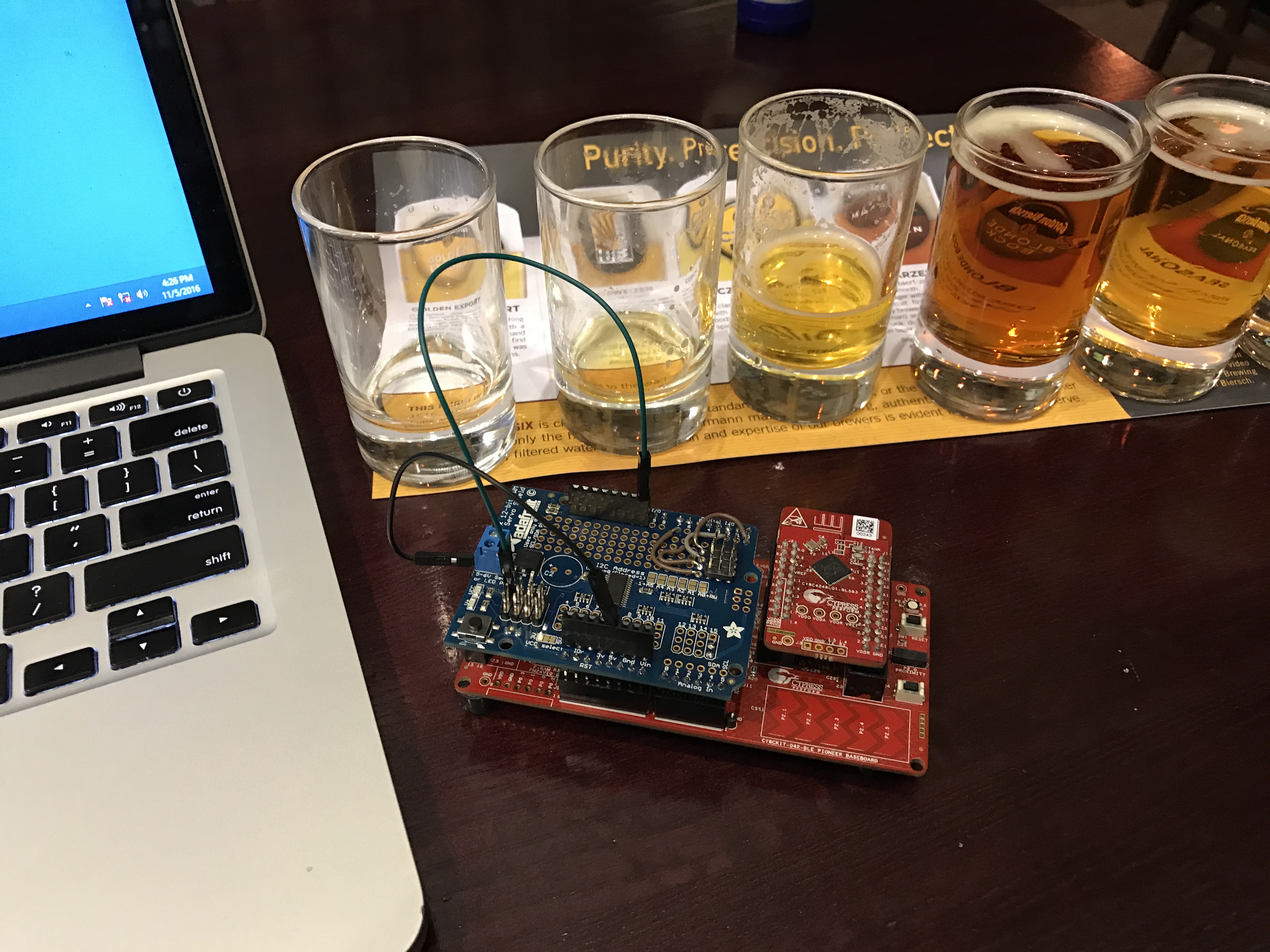
After I got off the airplane in Detroit I went to get some “dinner” and I wanted to try out the shield so I hooked it up:

img_3304

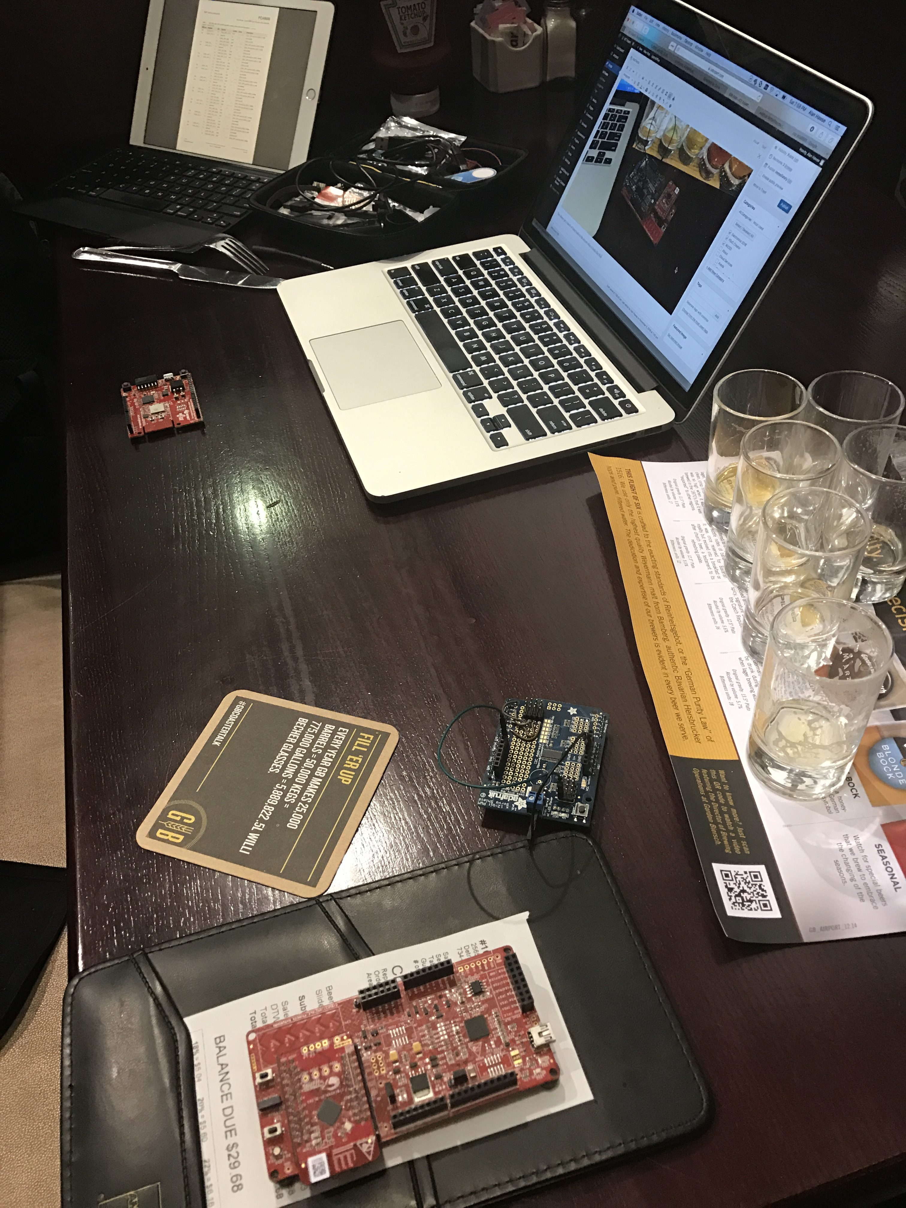
You always get a bunch of funny looks in the airport when your table looks like this:

img_3310This left me with only one problem.  How to drive the shield PWMs onto something that I could see… I didnt pack my Tek in my carry on (though I suppose I could have used one of those little scopes).  But, I digress.  What I decided to do is make the PSoC echo an input onto on output pin that was connected to an LED.  So, I drew this schematic.  This can only be done in with a PSoC because I used a logic gate in the UDB to flip the 9685 PWM from Low to High so that my active low LED would work right.

screen-shot-2016-11-05-at-8-02-36-pm

Next I fly to Charles De Gaul, the suckiest airport in the first world.  What will I do on the airplane there?  I don’t, but given those empty beer glasses I may sleep.  More to follow when I get to Germany.

Electronica + WICED + The Robot Arm

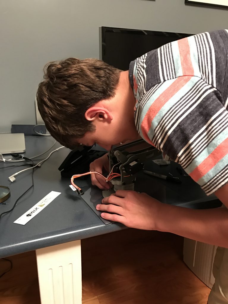
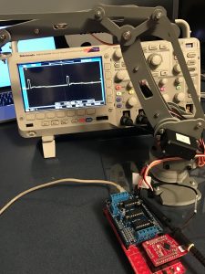
The good news is that the Robot Arm arrived from Amazon, which I was very happy about because it was a day late.  The even better news is that it works like a charm.  First I needed to assemble it, which I did with a little bit of help from my able lab technician and a trip to Lowe’s to get a base.

img_0003

Then “we” attached the base to the Robot.

img_0008

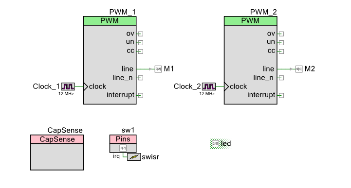
After the robot arm was put together on the base, I needed a little bit of firmware to run it.  First the schematic:  You can see that I have

  1. Two PWMs – one for each Servo motor
  2. A Capsense slider to move one of the axis on the robot
  3. A switch and LED to turn On/Off the PWMs

screen-shot-2016-11-05-at-7-04-50-am

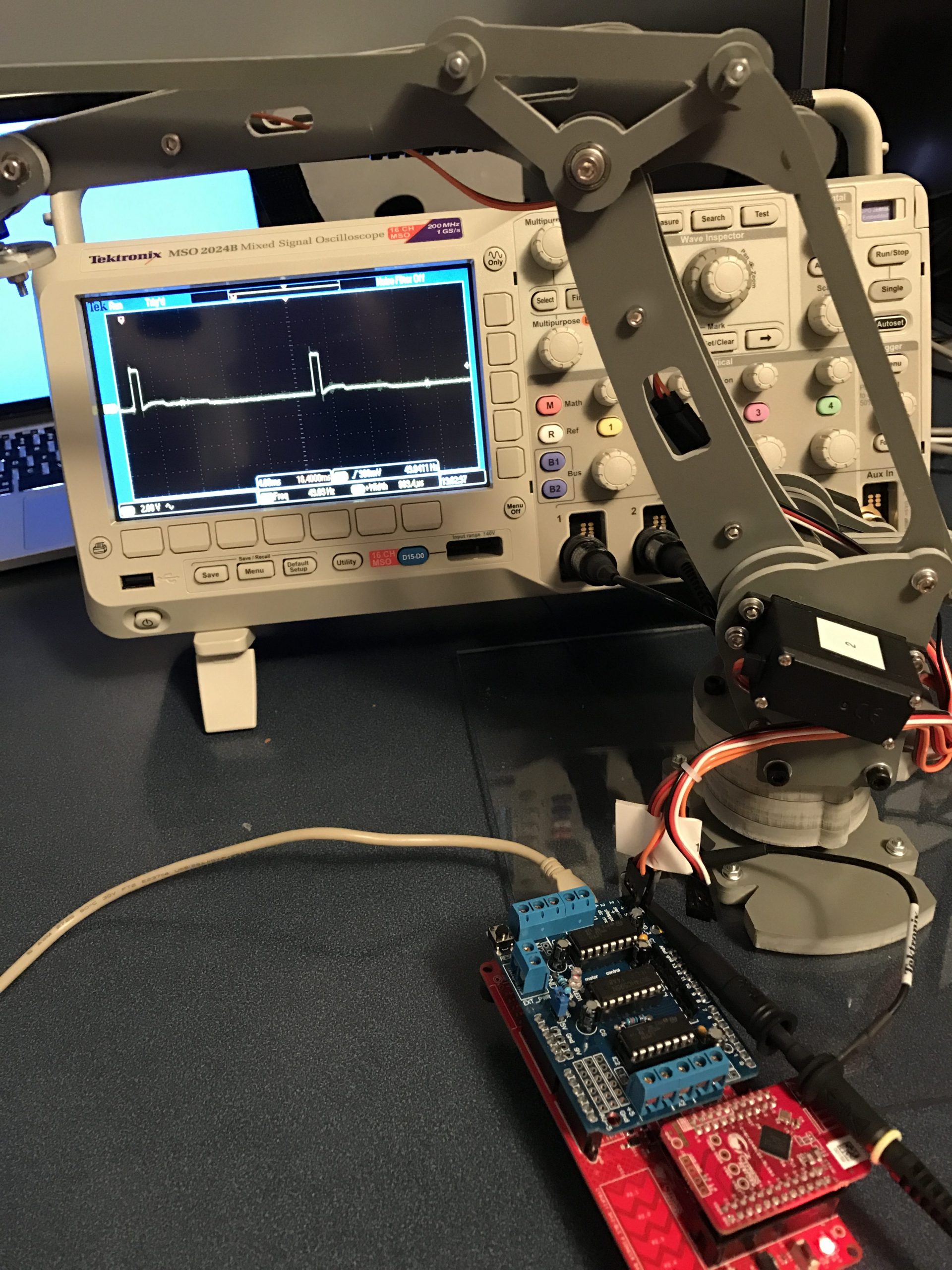
The robot arm has 4 “axis” which are each controlled by “servo” motors.  Servo motors have a small controller built into them that takes an input signal that is created by a PWM and turns the motor to the right place.  To drive the motor you need a input signal that is 50HZ, with a high pulse that ranges from ABOUT 1ms to 2ms.  When the pulse is 1ms the motor is all the way one direction, when the pulse is 2ms it is all the way the other direction.  To make the motor do what you want you give it a pulse somewhere in the middle, for instance if you want it to be half way then the pulse width is 1.5ms.

The easiest way to make this work is with a Pulse Width Modulator (PWM).  Conveniently enough, the PSoC4 BLE that I am using to build this project has 4 of them.  I set the input clock on the PWM to 12MHz, then I turned on the prescaler to divide by 4.  I then set the period to 60000.  Given all of that, the output frequency is 50hz.  which you can calculate by 12,000,000 / 4 / 60,000 = 50.  Given the period is 50HZ and there are 60000 clock ticks per period, each tick is 3us.  To make things easier on the rest of the system I want to give the input a range between 0% and 100% (as an Integer).  This lets me calculate the number of ticks I need to set the pulse width.  The formula is 3*(1000 + 10*percent).  I determined this empirically with an oscilloscope and changing the values to see the range of motion of the Robot Arm.

img_0012 img_0013

To achieve all of this, the PWM configuration is:

screen-shot-2016-11-04-at-7-49-33-pm

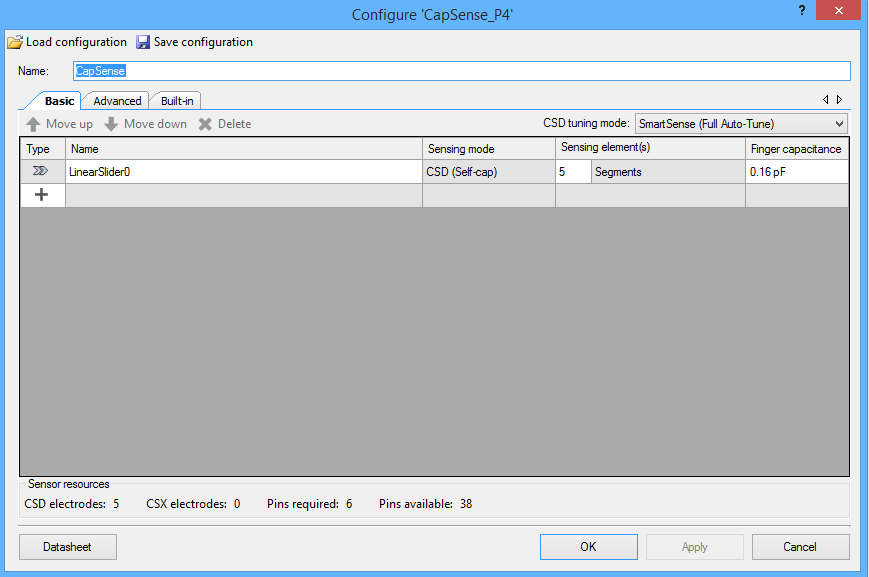
Now I configure the CapSense block to have a linear slider.

screen-shot-2016-11-04-at-7-52-55-pm

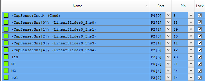
Finally I assign the pins:

screen-shot-2016-11-05-at-7-11-02-am

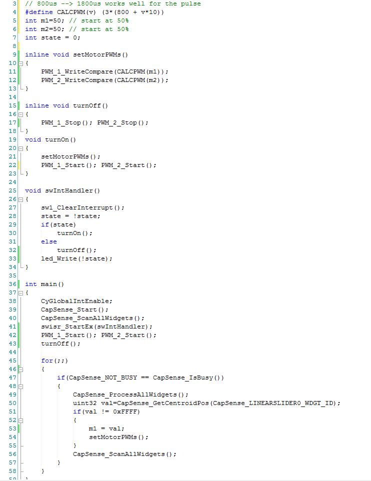
And a little bit of firmware:

Line 4 is a #define macro that calculate the correct compare value for the PWM.  After a little bit of experimenting with the Robot I figured out that it really wants the PWM to range between 800 microseconds and 1.8 milliseconds.

Line 5-7 initialize the original position of the PWM

Line 15-19 and 19-23 are helper functions which just turn on and off the PWMs.

Line 25-34 is an interrupt handler that is trigger when the user presses the switch.  It toggles a global state variable, turns on or off the PWMs and turns on/off the led.

In main I get things going on lines 38-43.  Then start an infinite loop that reads the capsense, and if the value is set then I set the value for the PWMs.  Remember that the capsense slider returns a value 0-100 so I can use it directly.

screen-shot-2016-11-05-at-7-03-25-am

After all of that my lab technician once again test it:

Electronica & WICED & PSoC

I am headed to Electronica in Munich tomorrow.  Cypress has a maker space in our booth where I will be teaching people how to use our products.  For some reason they always give me a microphone which seems crazy given that I am a bit wild.  The last show or two I have done demos using PSoC BLE.  This time I thought that I would also add WICED to the mix… so what is it going to be?

I saw this video on the Amazon AWS IOT website where their CTO introduces the AWS IOT platform by showing a demo of a robot arm.  The arm is connected to the AWS IoT Cloud (in some magic way) and is controlled by a Leap Motion controller connected to the cloud (also magic).  I hope that both of them were connected using WICED WiFi… but who knows since de didn’t show what was up his sleeves.

I thought that was really lame that he just magically brought the robot arm and controller from under the table and didn’t actually show you how to make it.  I am not really into doing things half ass and I don’t believe in magic, so what I am going to do is show people how to actually build that… live… Ginsu Knife Tiger Style

No magic, other than the magic of PSoC and WICED.  So, the day before yesterday I ordered what I think is the same robot arm… and now I need to write a little bit of firmware.  This is what I am going to build:

electronica-wiced

The only thing that I am a little bit worried about is getting to the Amazon Cloud from the LTE router in an high radio traffic environment of an electronics show… If that turns out to be a problem then Ill have to figure something else out… which will make life interesting.

Over the several days Ill post the firmware and pictures as I get it sorted out.

Alan

Cypress Academy — WICED WiFi 101

I have spent almost every waking hour for the last month writing a textbook for my new Cypress Academy class.  The textbook (as you might gather from the title of this post) is called Cypress Academy–WICED WiFi 101.  It has been an adventure learning the chips, modules, development kits and most importantly the WICED Software Development Kit well enough to teach other people.  During the next few weeks Ill write about this experience and talk about my experience.

Here is a picture of the textbook.  First, as you can tell by the cover, two amazing, bad-ass engineers worked with me on book.   James Dougherty, came from the Broadcomm IOT group and is a WiFI bad-ass.  And Greg Landry a 27-year Cypress engineer par excellence.

img_3294

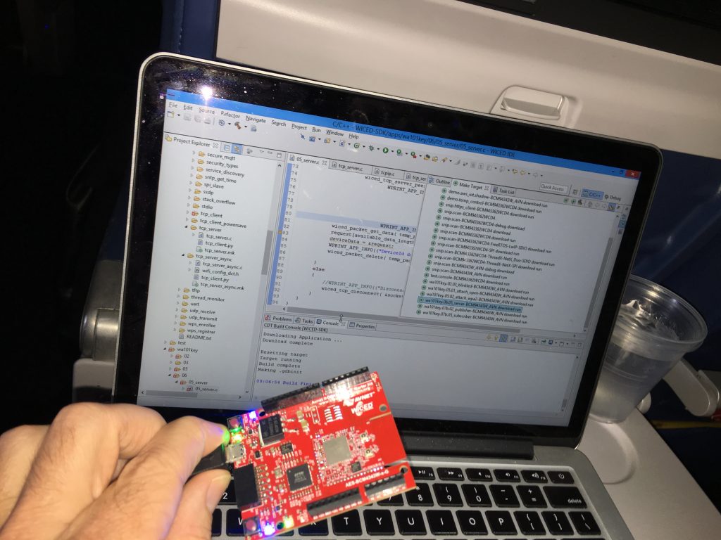
While I was flying to California I was frantically trying to finish the class.  Here is a picture of me programming the Development Kit on the airplane.  I will say that you get some strange looks from everyone else.  You can see the WICED-SDK on my screen.

img_3283

Finally during the week I taught the first class:

img_3285

Over the next few weeks I’ll write about the chapters and basically release it into the public domain.  Here is the table of contents:

Chapter

Time

Purpose

00-Intro

30

An Introduction to the class (this document)
01-Survey

120

A tour of the WICED WiFi SDK, WiFi Standard, Chips, Modules, and Kits.
02-Peripherals

120

How creating a new project and how to use chip peripherals such as GPIOs, interrupts, UART, I2C, etc.
03-RTOS

120

How to use the Thread-X RTOS in a WICED chip.
04-Library

0

How to use WICED libraries for file systems and graphics LCDs.
05-WiFi

60

How to connect to and interact with WiFi access points.
06-Sockets-TLS

60

Establishing (secure) communication using TCP/IP Sockets
07a-Cloud

07b-MQTT-AWS

07c-HTTP

07d-AMQP

07e-COAP

240

An introduction to cloud Application Layer protocols

Building a WICED IoT device using MQTT on the Amazon AWS

Building a WICED IoT device using HTTP

Building a WICED IoT device using AMQP

Building a WICED IoT device using COAP

08-Project

240

Class project.
09-Shield

0

Details on the analog co-processor shield board.
10-Glossary

0

Glossary of terms.


A Day off in Rome

Well this post doesn’t really have anything to do with IOT–actually anything to do with IOT.  But when in Rome…

It was a really beautiful day walking around in Rome after Maker Faire.  It was blue sky’s and about 70… but I am not sure what temperature that is in goofy units 🙂

Here are a few pictures that I took while wandering around here.

I had the taxi drop me at the Colossseum

img_3231

Then I walked down the street along the Roman Forum.

img_3234

In this video you can hear the amazing street band playing Jazz

Next I went around the corner where the church of Santa Luca e Martina

img_3239

Then into the Capitoline Museum.  Here is a bad-ass bust of Medusa by Bernini who did a bunch of amazing statues including the Four Rivers Fountain that I posted about earlier.

img_3245

And the Emperor Commodus as Hercules (apparently the guy was a real asshole)

img_3252

And unfortunately I don’t remember the name of this sculpture but it is amazing… look at the thighs on that dude. (Edit: I figured it out.  It is a composite of an old fragment of a discus thrower and a 17xx addition by Pierre Etienne Monnot who also sculpted another amazing statue called Andromeda and the Sea Monster.

img_3266

Another bad-ass who’s name I have forgotten from the Palaza Nuovo.  This is looking down the stairs on him… and those giant calves that look like they are carved out of marble. (Edit:  It is “The Colossal Status of Mars – sometimes misidentified as Pyrrhus” which for some reason they list as 360cm which is about 12 feet)

img_3268

Then onto Trevi Fountain

Maker Faire Insanity

I have spent the last weeks traveling like crazy and working to much…  The cool thing is that my travels have taken me to Maker Faire NYC and Maker Faire Rome.  I will be back onto the Pinball machine shortly… and I will have a new series going soon with WICED WiFi.

Here are some pictures:

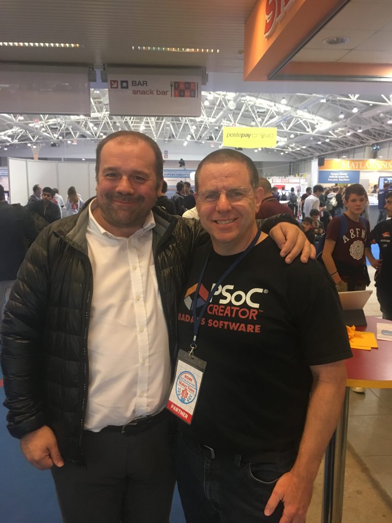
With Massimo Banzi in Rome:

img_3179

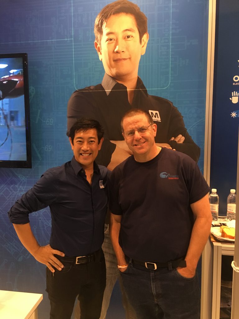
And Grant Imahara in the Mouser + Cypress booth in Rome:

img_3200

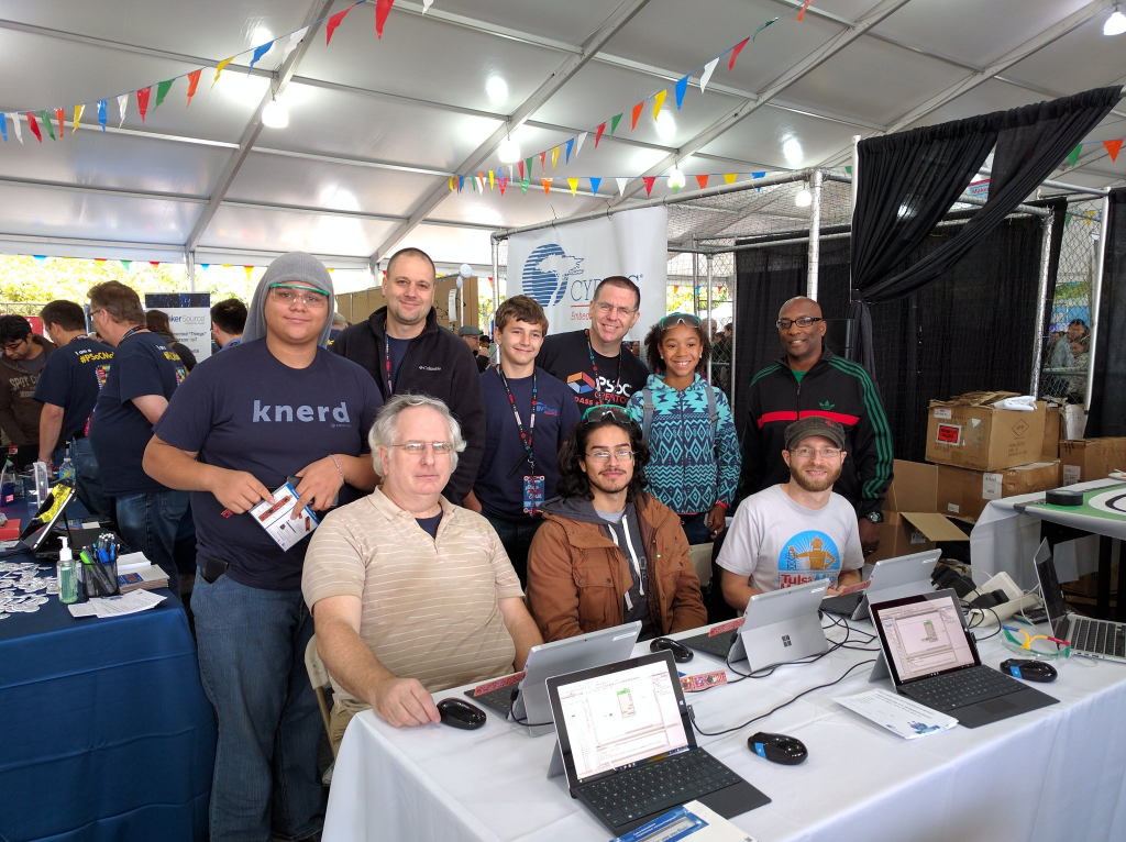
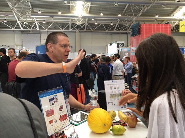
In New York, Nicholas and I taught people how to use PSoC.

img_3111

Here is one of the classes in NYC.

portable-network-graphics-image-156ba036437c-1

People playing the Fruita Piano in Rome.

portable-network-graphics-image-fe3bf62ad324-1

At the Piazza Novona in front of Fontana di Quattro Fiumi… this place is truly remarkable.

img_3188

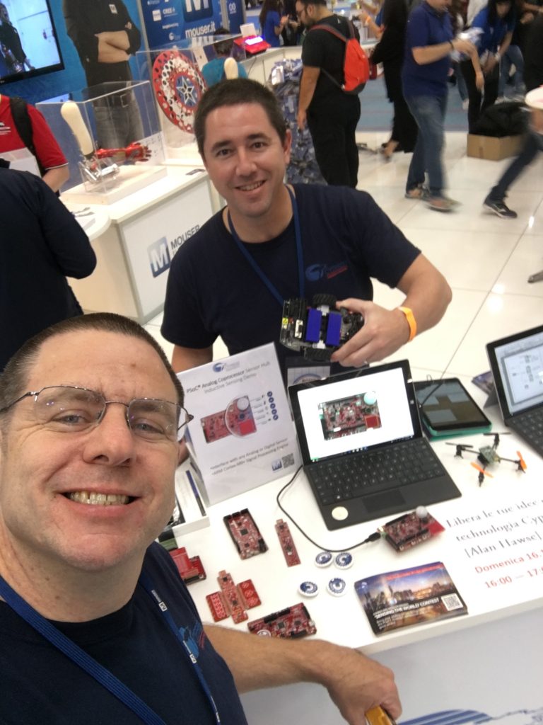
Jim and I at the booth in Rome.

img_3189

Maker Faire – Bay Area

IMG_2820

I am at the Maker Faire this weekend teaching people how to  program the PSoC.  We have a bunch of computer runnings PSoC Creator and I am giving out development kits.

Come to the Cypress booth and signup and I will teach you!

https://twitter.com/CypressSemi/status/734155415928217601

https://twitter.com/CypressSemi/status/734142119779000320

https://twitter.com/CypressSemi/status/734138496068124672

https://twitter.com/CypressSemi/status/734131371971469312

https://twitter.com/CypressSemi/status/734127268495134720

https://twitter.com/CypressSemi/status/734124734451843072

https://twitter.com/CypressSemi/status/734082357171363841


Git and SSH

Summary

In a previous post I talked about the steps I took to repurpose my old Mac Mini as a server.  In this post I will explain the steps that I went through to make it act as a “Git” server.  Although I am an active github.com user it is sometimes nice to have something stored locally as well.  The easiest (and best) way to make a git server on your network is to use SSH.  In order to make SSH work you need to know about encryption and keys.  I knew in an abstract way about encryption but I hadn’t really dug through how all of the parts operate in detail which I had to do to figure this out.  I will start by explaining the practical mechanics of encryption, and then take you through the rest of the steps to setup and use Git.

  1. Symmetric and Asymmetric Encryption: A Foundation
  2. Setup Git as user on your Server
  3. Create RSA Keys for a User
  4. Give user permission to write into Git User Account
  5. Create a new repository called “repoName”
  6. Using the new repository

Symmetric and Asymmetric Encryption: A Foundation

SSH stands for Secure SHell.   The reason it is called Secure is that it uses an encrypted channel for all communication.  But how can that be?  How do you get a secure channel going?  And what does it mean to have a secure channel?  What is secure?  This could be a very complicated topic as establishing a fundamental mathematical understanding of encryption requires competence in advanced mathematics that is far beyond most everybody on the face of this planet.  It is also beyond what there is room to type in this blog.  It is also far beyond what I have the ability to explain.  But, don’t despair.  The practical aspects of getting this going are actually pretty simple.

First a word of caution.  When you make the changes to your computers/network to make this stuff work, you are playing with fire.  If you are not careful, you will compromise the security of your system.  At this point all of the computer and operating system vendors have spent considerable amounts of time and money making computers safer by installing firewalls and closing security holes.  For as much as they have spent making security, the fucking hackers, the Chinese government and the assholes in US government have put 10x that energy into trying to steal your information.

All encryption does the same thing.  It takes un-encrypted data, combines it with a key, and runs it through an encryption algorithm to produce encrypted data.  You then transmit the encrypted data over the network.  When the other side receives the data it decrypts the encrypted data by combining it with a key, and running the decrypt algorithm.

There are two types of encryption schemes, symmetric and asymmetric.

Symmetric means that both sides use the same key.  That is, the key that you encrypt with is the same as the key you unencrypt with.  Examples of this type of encryption include AES and DES.  This type of encryption is preferred because it is very fast and secure.  However, both sides need to know the key before you can use it.  If you have never talked before how do you get both sides to know the key?  This is a big problem.

Asymmetric, often called Public Key, encryption techniques use two keys that are mathematically related.  The keys are often referred to as the “public” and the “private” keys.  The private key can be used to decrypt data that the public key encrypted and vis versa.  This is super cool because you can give out your public key to everyone, they can encrypt data, then only your private key can be used to decrypt it.  The problem with this encryption technique is that it is slow.

What now?  The most common technique to communicate is to

  • You open an unencrypted connection to a server
  • You give out your public key to the server
  • The server then creates a random symmetric key
  • The server then encrypts its newly created random symmetric key using your public key and sends it back to you
  • You use your private key to decrypt the symmetric key
  • You open a new channel using symmetric key encryption

public-key-exchange

This scheme is completely effective against eavesdropping.  What happens if someone eavesdrops the original public key?  That is OK because they won’t have the “client private key” required to decrypt the symmetric key.  What this scheme doesn’t work against is called man-in-the-middle (MIM).  An MIM attack works by

  • You open an unencrypted connection to a server [but it really turns out that it is a MIM]
  • You send your public key to the MIM
  • The MIM opens a channel to the server
  • The MIM sends its public key to the server
  • The Server encrypts a symmetric key using the MIMs public key and send it back to the MIM
  • The MIM decrypts the symmetric key using its private key
  • The MIM send you the symmetric key encrypted with your public key
  • You unencrypt the MIM symmetric key using your private key
  • Then you open new channel to the MIM using the symmetric key
  • The MIM opens up a channel to the server using the symmetric key

Once the MIM is in the middle it can read all of the traffic.  You are only vulnerable to this attack if the MIM gets in the middle on the first transaction.  After that things are secure.  However, the MIM can easily happen if someone gets control of an intermediate connection point in the network-like e.g. WIFI access point.  The only way to protect against MIM attacks is to have a Certificate Authority (CA).  A CA works by verifying that the Public Key actually belongs to who you think it belongs to by using a cryptographic hash.  If the MIM sends you its public key then you check with the CA and find out that the MIM public key does not belong to the server that you are trying to connect to, then you know that you are being subjected to an MIM attack.  How do you prevent an MIM when talking to a CA?  This is done by building in known valid certificates into your program.   This morning when I looked at the certificates on my Mac there were 179 built in, valid certificates.  This is cool for HTTPS but what about SSH?  With SSH you will need to manually verify the public key of the host you are attaching to.  There is a nice discussion of this topic here.

When you configure your GIT server you will manually copy your public keys onto the GIT server.  This will prevent MIM attacks and will support the establishment of a symmetric encrypted connection.  This is called an out-of-band (OOB) key exchange.  On github this is done with a browser.   For other security systems it could be a USB stick or other scheme.  More on that later.  Now onto the mechanics of making the Git server work.

Setup Git as user on your Server

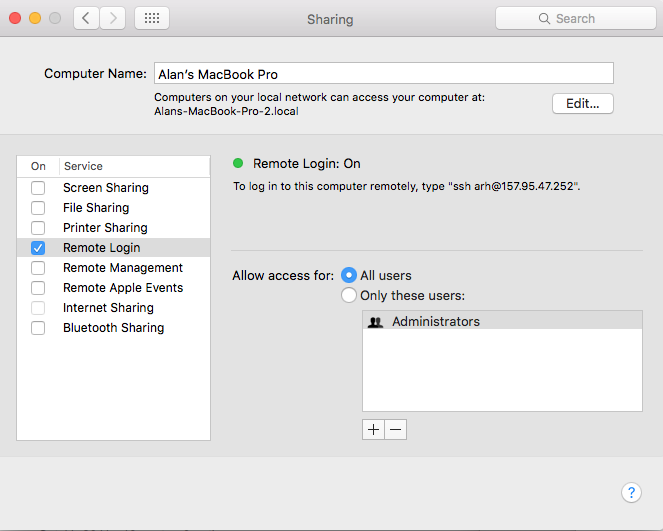
First you need to enable Remote Login (ssh) from the System Settings –> Sharing.  Make sure that it enabled for All Users
Remote Login

Then you need to turn on the firewall  System Settings –> Security & Privacy
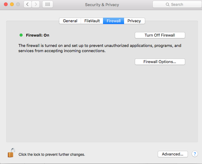
Firewall

Press the “Firewall Option…” turn off the “Block all incoming connections” and then allow Remote Login (SSH)
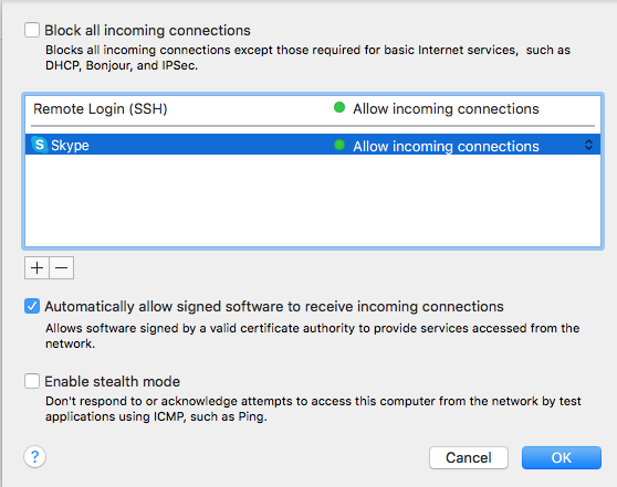
Firewall Remote Login

Then you need to create a “git” user account.  The account should be a standard account.

Create GIt Account

The next step needs to be done in a terminal window.  You need to have root access (your account need to be authorized as an administrator) to follow these steps.  This will create the place to store the SSH RSA Keys.

command comment
su – git log in a the git user.  You will need to type the password that you set when you setup the git account
mkdir .ssh Create the directory with the public and private secure shell keys
chmod 700 .ssh This directory should only be redable by the git user
cd .ssh
touch "authorized_keys" Create a file that you will add public keys to of the people who are allowed to upload to this server
sudo chpass -s /usr/bin/git-shell git Make the git user so that it can only do git commands.  This is a way to enhance security by not letting the git account do anything other than local git commands.

Create RSA keys for a user

In order for a user to have access to the git account on the server he will need to have RSA Keys.  Specifically, in the ~/.ssh directory of the user you will need two files, id_rsa and id_rsa.pub  These files are the public and the private keys of the user.  When you run the command

  • ssh-keygen -t rsa -b 4096 -C “user@computer”

it will first ask you where to store the keys.  If you already have keys it will give you the option to store them someplace other than the default location.  Then ssh-keygen will ask you for the password to encrypt the private key file.  I don’t use a password on my private key file, but the security would probably be better if I did.  The “-C” option just inserts the text in quotations into the key file as a comment so that when you look at the file you can figure out what the key is associated with.
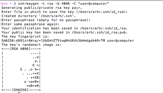
Screen Shot 2016-03-29 at 7.24.22 AM

You can look at the MD5 signature (which is what github displays) of a public key by running

ssh-keygen -E md5 -lf  id_rsa.pub

Give user permission to write into your Git User Account

In order for a user to be able to access the git server you will need to append his public key to the “~git/.ssh/authorized keys” file.  As I talked about above, in the users home directory you will find a directory called “.ssh”.  In that directory there will be two files, one is called “id_rsa.pub” which is the RSA public key, the other is called “id_rsa” which is called the private key.  You should be very careful to only copy the public key.

  • sudo cat id_rsa.pub >> ~git/.ssh/authorized_keys

In this example both users were on the same computer, but they don’t have to be.  In that case you will need to copy the file some other way (ftp, scp, the browser, …)  Then append it to the ~git/.ssh/authorized_keys file.

Create a new repository called “repoName”

Once you have everything setup with the git user and the SSH RSA keys you will need to create a “bare” repository

  • cd ~git
  • sudo git init –bare repoName.git
  • sudo chown -R git repoName.git

Using your new repository

The last thing to do is to setup git remotes for the new repository.  To do this, on your client machine you can either clone it with

  • git clone git@githost:repoName.git

Or if you have an existing repo you can

  • git remote origin git@githost:repoName.git
  • git push origin master


Other random topics

When I was trying to figure out how all of this worked I found a couple of places (on google) that talked about modifying the file /etc/ssh/sshd_config.  This turned out to be a red herring as the default Mac OS X settings work fine.

When you open a new shell on your client computer, then start your first SSH, the client shell automatically starts a daemon called “ssh-agent”.  This daemon reads all of your key information and caches it.  You can see the information that it is storing by running “ssh-add -l”.  If for some reason you change your rsa keys you will need to either restart the daemon or tell it to read the new keys “ssh-add ~/.ssh/id_rsa”.  You can read more about this in these articles ssh-agent-forwarding and ssh-agent-keys in the github documentation.

If for some reason you are using multiple rsa key files then you need to create a “~/.ssh/config” file to setup which key is used in which situation.  I have this situation because I use github for my personal stuff as well for my iotexpert stuff.   By default ssh uses the keys in “~/.ssh/id_rsa”.  If you need to setup a different key for other hosts you can:

  • Create an ssh name called “github.com” which uses “~/.ssh/id_rsa”
  • Create and ssh name called “iotexpert.github.com” which uses “~/.ssh/id_rsa_iotexpert”
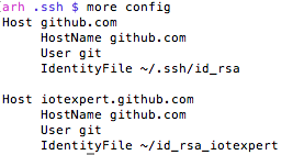
Screen Shot 2016-03-30 at 7.14.13 AM

There is a daemon running called the ssh-agent.  It is used to cache and deliver the keys.  You can see what keys it knows about by running

ssh-add -L

You can delete the cache by running

ssh-add -D

You can add keys to the cache by running

ssh-add ~/.ssh/id_rsa

ssh-add ~/.ssh/id_rsa_iotexpert

To test all of this (with github) you can run

ssh -T git@iotexpert.github.com

or

ssh -T git@github.com

These commands will test the key exchange to make sure that the right key is being mapped to the correct user.

Then to setup the different remotes I do

  • git remote add origin git@github.com/someuser/repository.git to use the id_rsa key
  • git remote add origin git@iotexpert.com:iotexpert/repository.git to use the id_rsa_iotexpert key

The thing that was intensely confusing is “iotexpert.github.com” isn’t actually the name of a computer.  It is just an ALIAS that ssh uses… when SSH runs it looks in the config file and if it sees a “Host” alias that matches what you typed, then it substitutes the value of “HostName” in place of where you gave it “Host”.


Embedded World 2016

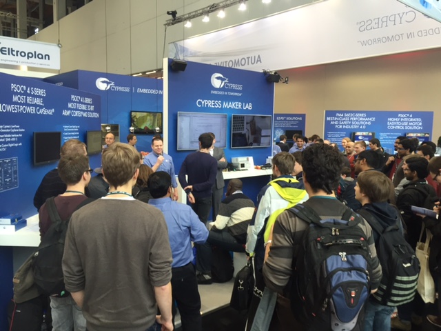
I spent the past week in Nuremberg, Germany at the Embedded World conference doing my day job.  At the show, I spent some of my time teaching people how to program PSoCs.  For some crazy reason they thought that it would be a good idea to give me a microphone and find out what comes out of my mouth- generally that is something semi-crazy and it is always loud.    Here is a picture of me talking to the crowd (I am the one in the blue shirt facing the crowd)
IMG_5570

So what did I talk about?  Well, at this show, IOT was the big buzz.  So I decided to teach people how to make an IOT device using the Cypress PSoC 4 BLE.  This was similar to a recent video tutorial that I had made.  I started with a blank schematic in PSoC Creator and a CY8CKIT-042BLE,  I then added a capsense slider, an LED, a PWM, and the BLE component.  Then I showed people how to write the firmware.  I did all of this live, which can make things interesting at times.  At one point on Thursday, my wife called from KY and it seemed like a good idea to answer the phone.  She was a good sport when I put the microphone next to my cell phone and talked to her live during while I was presenting.

You can get the step by step instructions for this project on the cypress.com video tutorials website.  While I talked, the Cypress people handed out free development kits which was a big hit with the crowd.

The morning of the last day I reflected back on the last several years and realized that this show was a coming of age for the Cypress PSoC 4 platform.  We finally had a very robust family of parts from the tiny PSoC 4000 all the way to the large PSoC4200L.  The family had an ARM Cortex M0, Capsense, BlueTooth Smart, CAN, LIN, USB, ADCs, SPI, UART, OP Amps, Analog Mux and Programmable Digital Blocks.  In addition to the chips, we had a big library of well written application notes,  a bunch of cool development kits and best of all we had PSoC Creator which is an amazing, magical, free IDE for building your projects.

On Monday, we had just announced the new PSoC4000S (S stands for small) with a new low power capsense block that included mutual capacitance sensing.  During the show we were using a new “stamp” board to show off the chip.  In the next post Ill show you what I did on the airplane ride home from Germany.

IMG_2703