IoT Design with Cypress PSoC® 6 MCUs and Wi-Fi/Bluetooth using Arm® Mbed™
#
Lesson
GitHub Project
0
Introduction
1
Developer Resources
2
Your First Project & The Blinking Thread
https://github.com/iotexpert/mouser-mbed-02.git
3
Display Thread
https://github.com/iotexpert/mouser-mbed-03.git
4
Temperature Thread
https://github.com/iotexpert/mouser-mbed-04.git
5
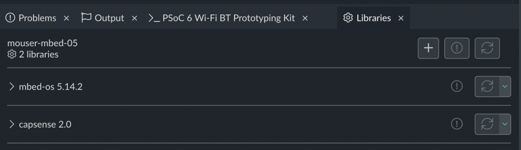
CapSense Thread
https://github.com/iotexpert/mouser-mbed-05.git
6
WiFi & NTP Thread
https://github.com/iotexpert/mouser-mbed-06.git
7
The CY8CKIT-062-WiFi-BT
https://github.com/iotexpert/mouser-mbed-07.git
8
Amazon AWS MQTT Thread - Part1
https://github.com/iotexpert/mouser-mbed-08.git
9
Amazon AWS MQTT Thread - Part2
https://github.com/iotexpert/mouser-mbed-09.git
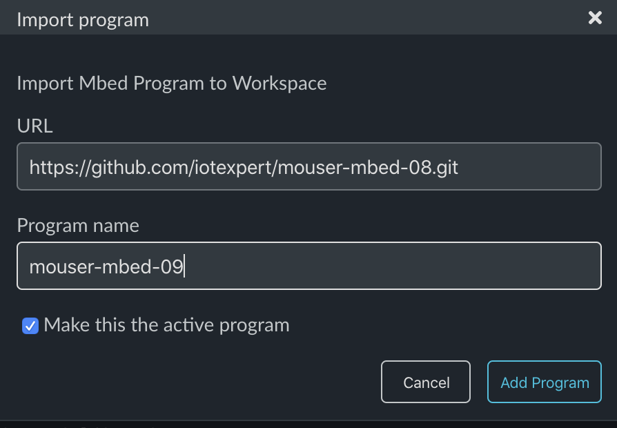
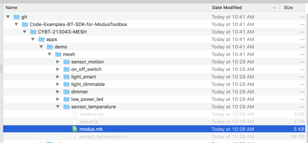
You can “mbed import https://github.com/iotexpert/mouser-mbed-09.git“ to make a copy of the project in your workspace.
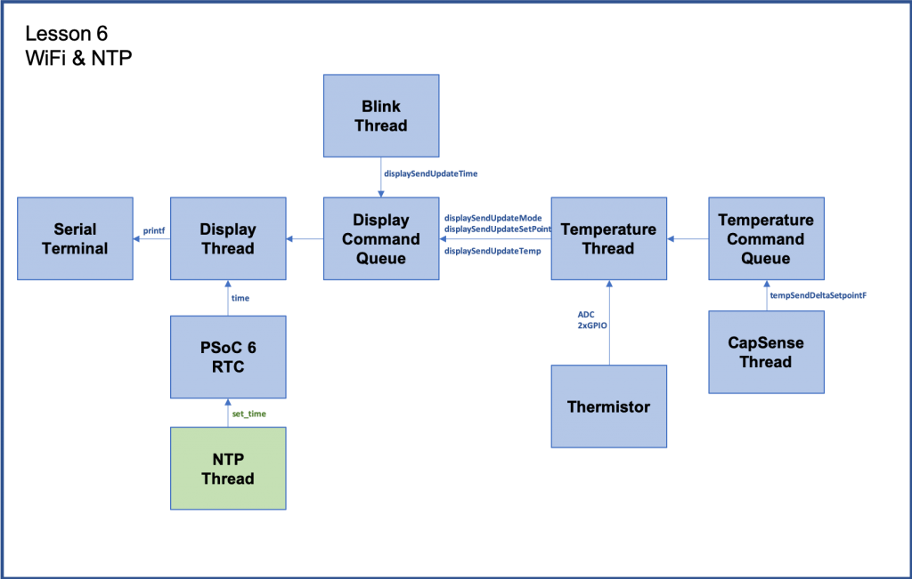
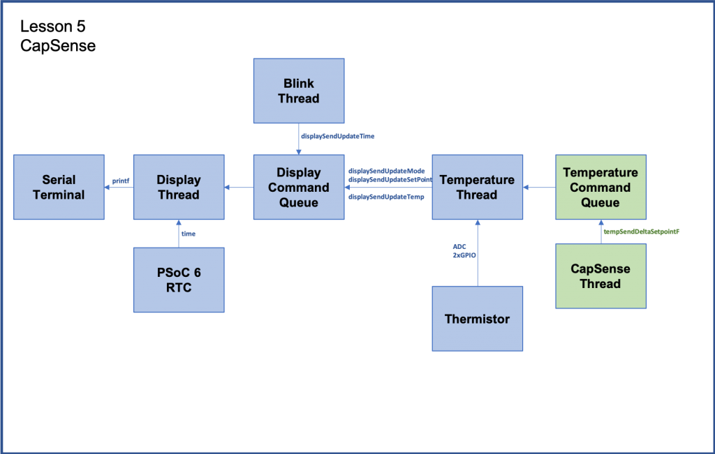
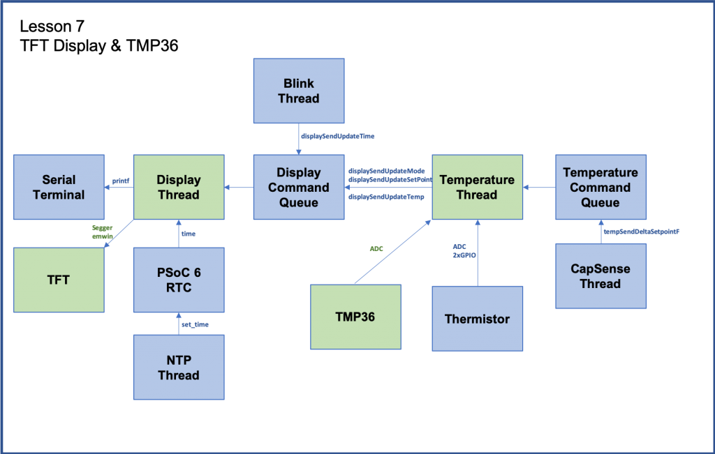
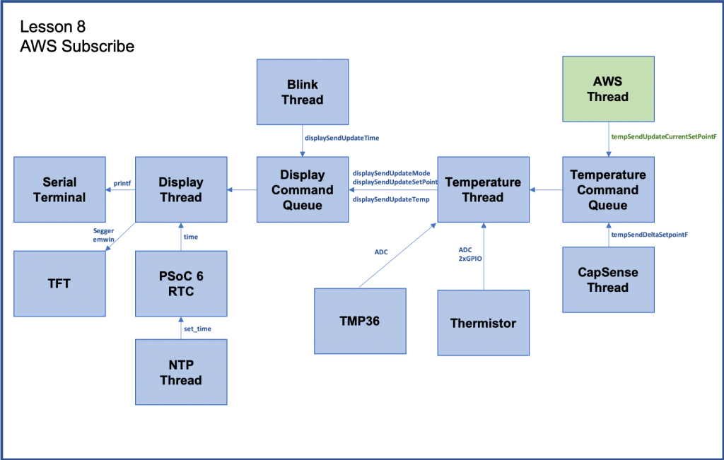
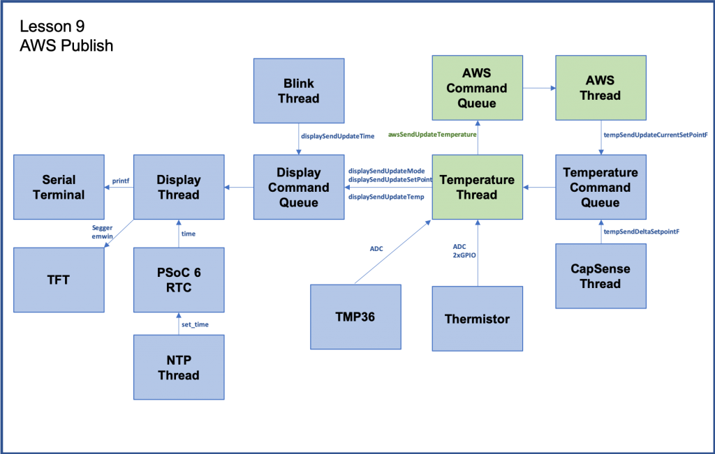
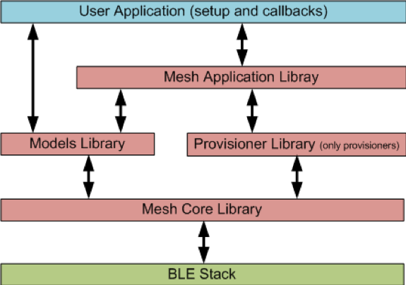
The final architecture of the thermostat looks like this.

Summary
In Lesson 04 I will add temperature sensing to the system.
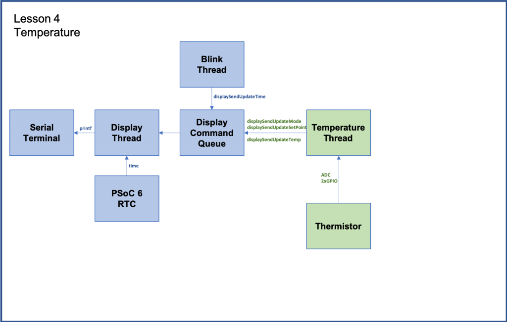
The new thread called “temperatureThread” acts as the actual guts of the thermostat. It reads the temperature sensor, keeps track of the setPoint of the system and turns on and off Heat and Cooling. Notice that it doesn’t know anything about displaying information, it just uses the functions calls we created for the displayThread.
To implement this I will:
- Explain Thermistors
- Import lesson03
- Create and code temperatureThread.h
- Create and code temperatureThread.cpp
- Fix blinkThread.cpp
- Update main.cpp
- Build, Program and Test
Thermistor
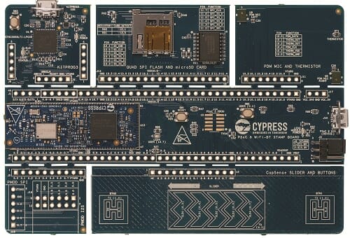
On the wing of the CY8CPROTO-062-4343W there is a thermistor that you can use to measure temperature. What is a thermistor? It is simply a resistor that changes resistance in a known way based on temperature.
If you know the resistance you can calculate the temperature using the Steinhart-Hart equation. Here is the Thermistor Wikipedia article.
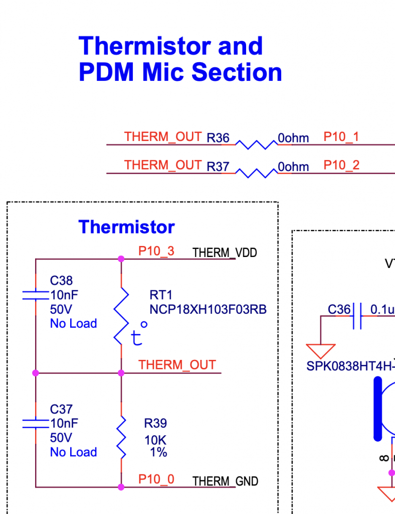
When you look at the schematic for the development kit you can see how the circuit is attached to the PSoC.
Basically, a known 10K resistor in series with the thermistor with a measurement point between them. To calculate the resistance of the thermistor you use Ohms low, V=IR. Or even better R=V/I.
To use this circuit you need to assign a voltage to the THERM_VDD, use a DigialOut to drive 3.3v to that signal and a DigialOut to drive ground to the THERM_GND.
Then use the ADC to find the voltage for THERM_OUT
To do the calculation, first the Thermistor voltage is THERM_VDD-THERM_OUT.
Then you need to get the current. To do this you calculate the current through the reference resistor I=V/R or I=(THERM_OUT/10K). This will be the same current as the Thermistor.
Now you can calculate the thermistor resistance.
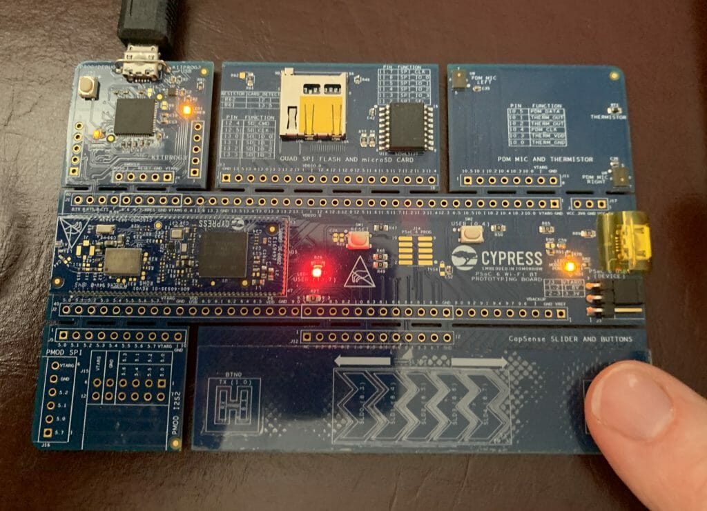
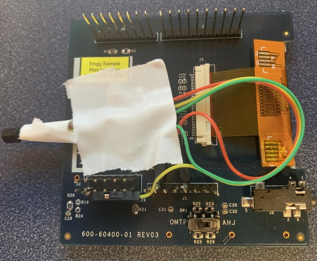
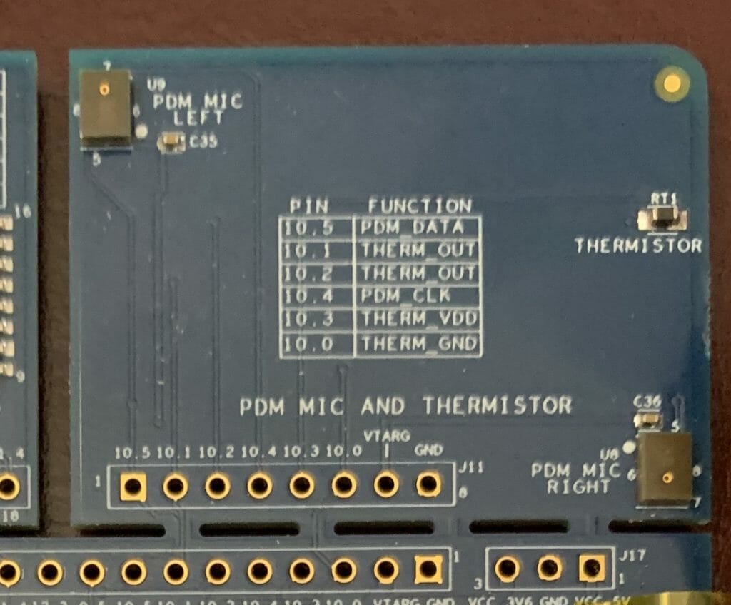
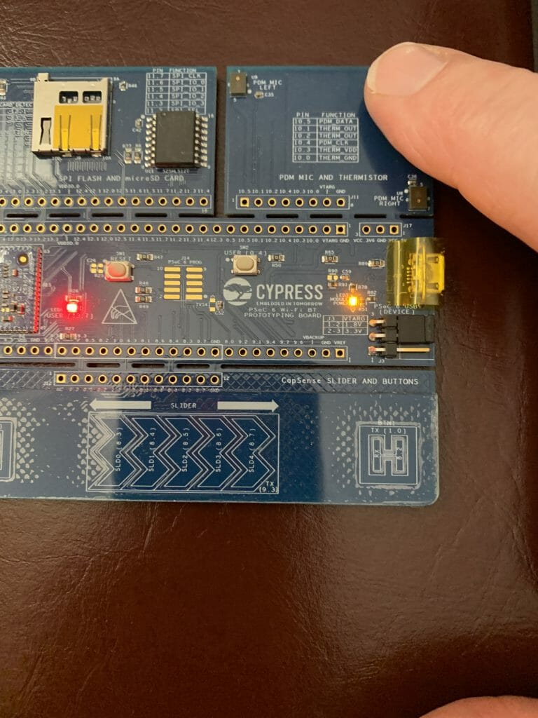
Here is a picture of the thermistor on the board.
Here is the code that implements the thermistor measurement.
static DigitalOut thermVDD(P10_3,1);
static DigitalOut thermGND(P10_0,0);
static AnalogIn thermOut(P10_1);

static void readTemp()
{
    float refVoltage = thermOut.read() * 2.4; // Range of ADC 0->2*Vref
    float refCurrent = refVoltage  / 10000.0; // 10k Reference Resistor
    float thermVoltage = 3.3 - refVoltage;    // Assume supply voltage is 3.3v
    float thermResistance = thermVoltage / refCurrent;
    float logrT = (float32_t)log((float64_t)thermResistance);

    /* Calculate temperature from the resistance of thermistor using Steinhart-Hart Equation */
    float stEqn = (float32_t)((0.0009032679) + ((0.000248772) * logrT) +
                             ((2.041094E-07) * pow((float64)logrT, (float32)3)));

    float temperatureC = (float32_t)(((1.0 / stEqn) - 273.15)  + 0.5);
    temperatureF = (temperatureC * 9.0/5.0) + 32;
}
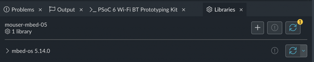
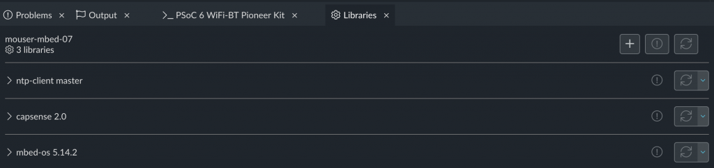
Import Lesson 03
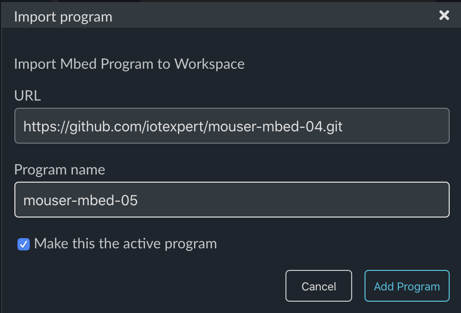
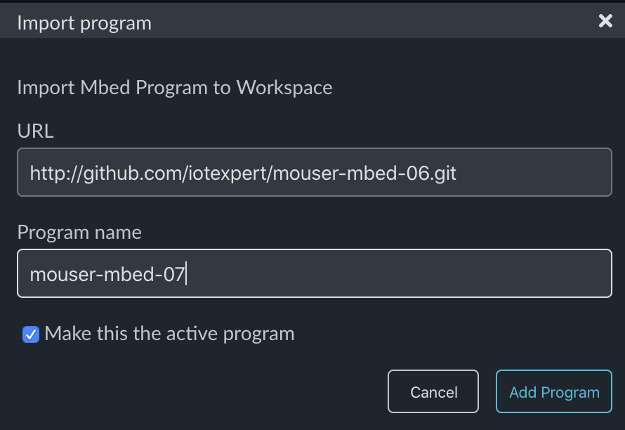
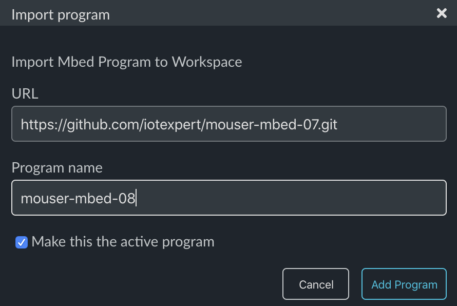
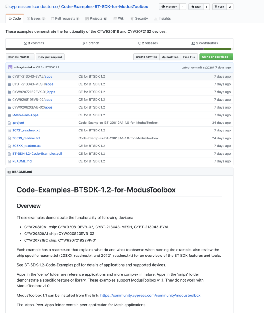
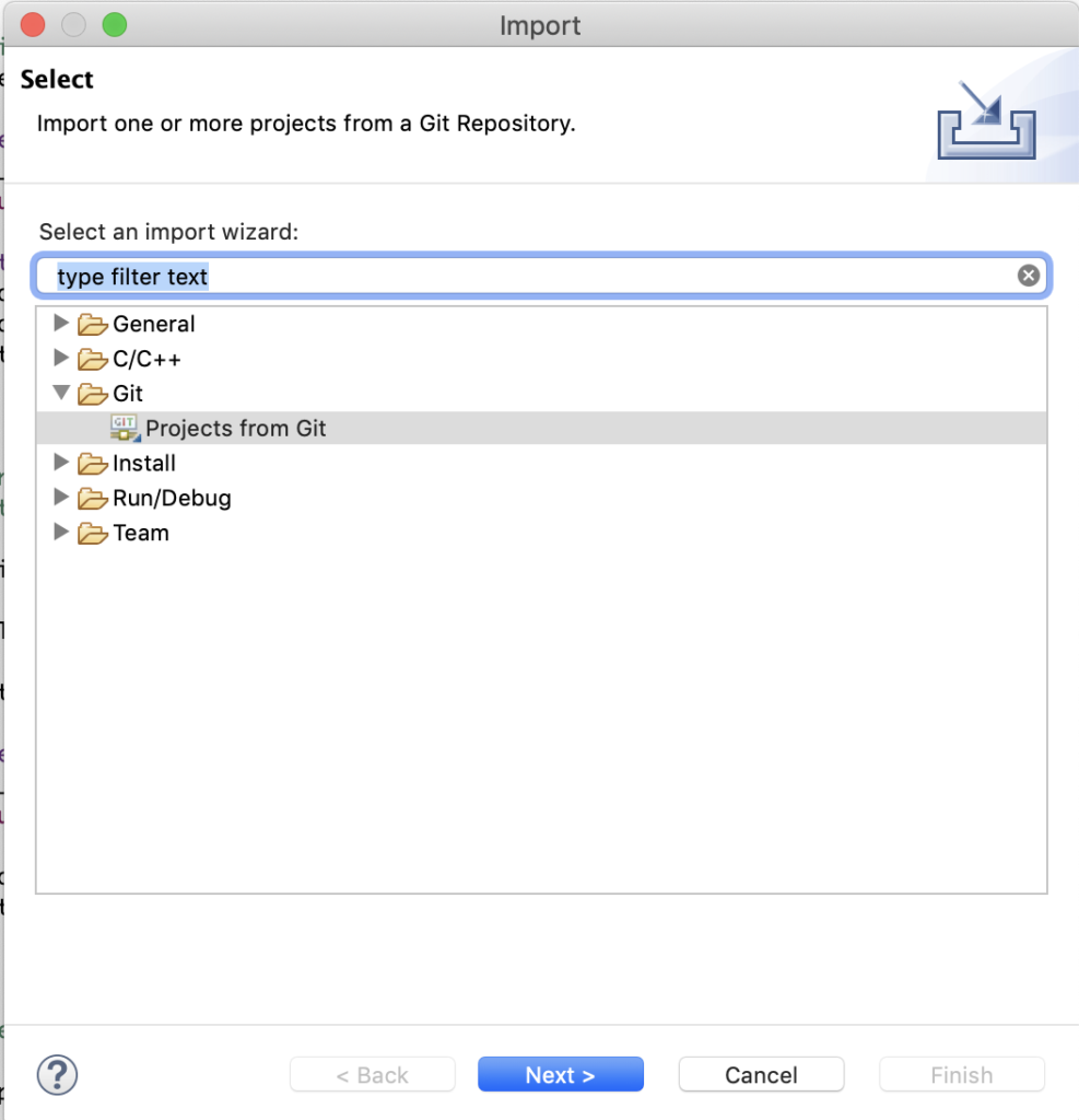
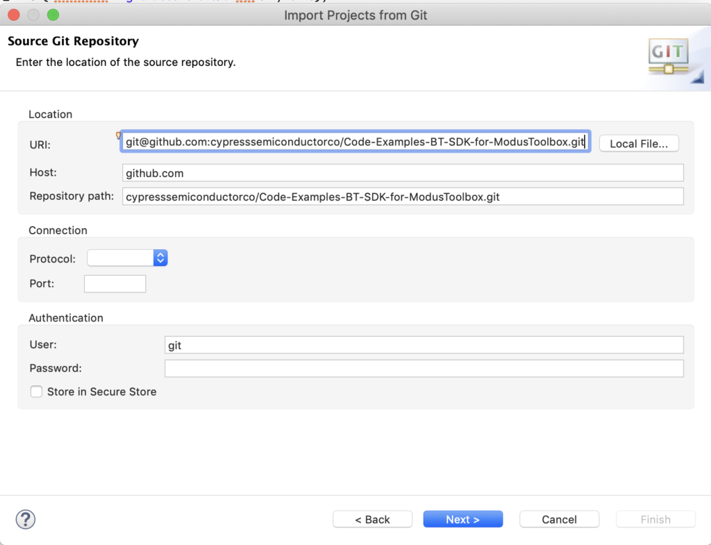
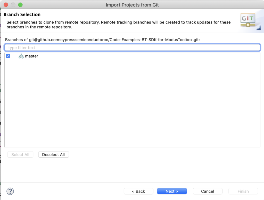
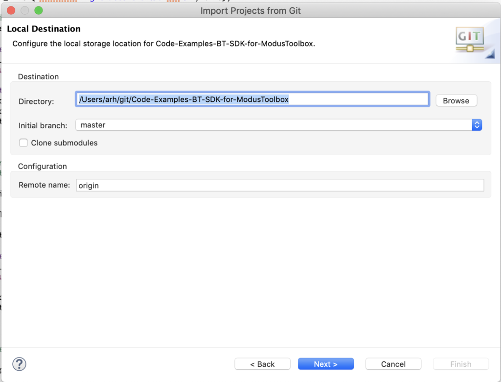
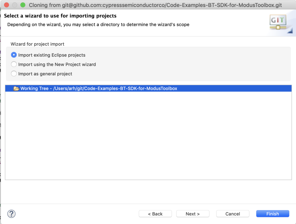
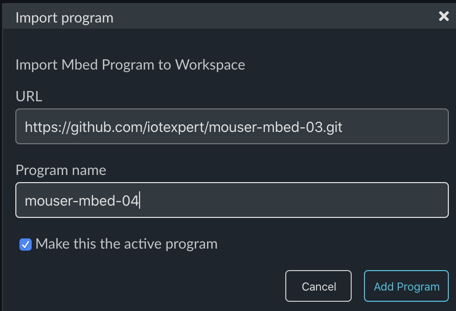
To build the project, start by importing Lesson 03:
https://github.com/iotexpert/mouser-mbed-03.git
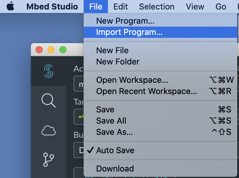
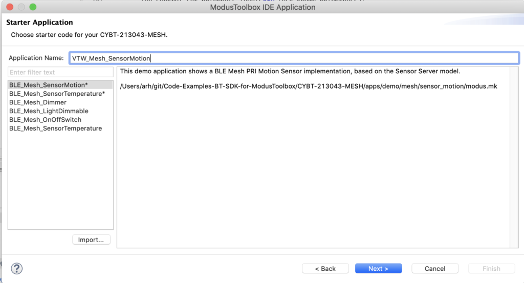
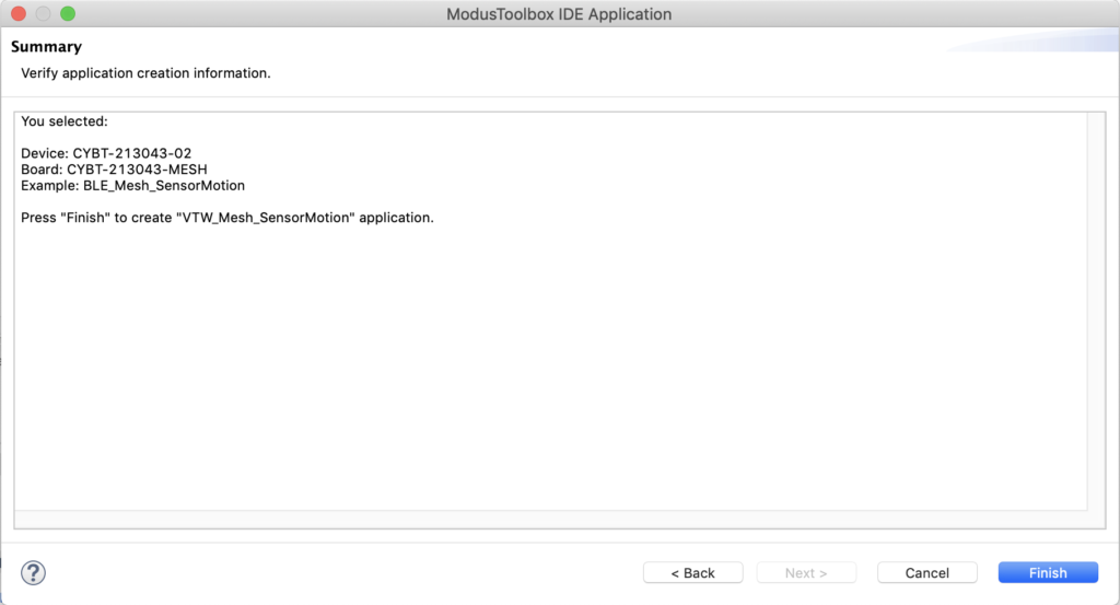
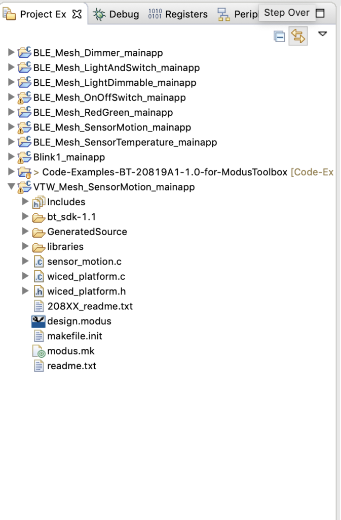
Give it a new name of “mouser-mbed-04”:
Create and code temperatureThread.h
As before we want a thread for the temperature system called “temperatureThread.h”. Create the “dot h”:
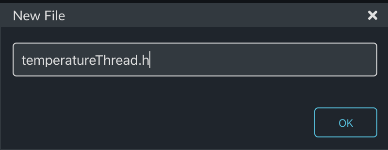
This file will just declare the thread and interface functions.
#ifndef TEMPERATURE_H
#define TEMPERATURE_H

void temperatureThread();

void tempSendUpdateSetpointF(float setPoint);
void tempSendDeltaSetpointF(float delta);


#endif
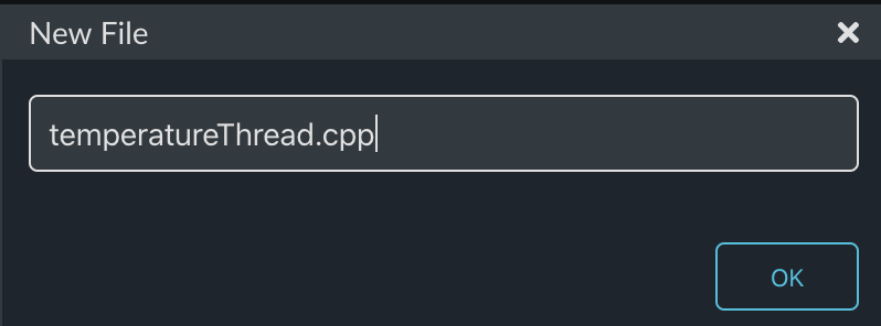
Create and code temperatureThread.cpp
Now we need the actual thread. Make the new file “temperatureThread.cpp”
This thread will have two state variables. One for temperatureF and one for the setPoint of the thermostat.
This thread will also have a queue just like the displayThread. This queue will be used to let other parts of the system change the setPoint. One command to make a “delta” change e.g. “go up 1 degree” and one command to make an absolute change e.g “set to 78 degrees”
#include "mbed.h"
#include "temperatureThread.h"
#include "displayThread.h"

static float temperatureF;
static float setPoint = 75.0;

static void readTemp();

typedef enum {
    CMD_setPointDelta,
    CMD_setPoint,

} command_t;


typedef struct {
    command_t cmd;
    float    value;   /* AD result of measured voltage */
} msg_t;
As before to make things easier for the other parts of the system to send messages to the queue, I create functions to send the two commands.
void tempSendDeltaSetpointF(float delta)
{
    msg_t *message = mpool.alloc();
    if(message)
    {
        message->cmd = CMD_setPointDelta;
        message->value = delta;
        queue.put(message);
    }
}

void tempSendUpdateSetpointF(float setPoint)
{
    msg_t *message = mpool.alloc();
    if(message)
    {
        message->cmd = CMD_setPoint;
        message->value = setPoint;
        queue.put(message);
    }
}
Now you need the function to read the temperature and update the state variable temperatureF
static DigitalOut thermVDD(P10_3,1);
static DigitalOut thermGND(P10_0,0);
static AnalogIn thermOut(P10_1);

static void readTemp()
{
    float refVoltage = thermOut.read() * 2.4; // Range of ADC 0->2*Vref
    float refCurrent = refVoltage  / 10000.0; // 10k Reference Resistor
    float thermVoltage = 3.3 - refVoltage;    // Assume supply voltage is 3.3v
    float thermResistance = thermVoltage / refCurrent;
    float logrT = (float32_t)log((float64_t)thermResistance);

    /* Calculate temperature from the resistance of thermistor using Steinhart-Hart Equation */
    float stEqn = (float32_t)((0.0009032679) + ((0.000248772) * logrT) +
                             ((2.041094E-07) * pow((float64)logrT, (float32)3)));

    float temperatureC = (float32_t)(((1.0 / stEqn) - 273.15)  + 0.5);
    temperatureF = (temperatureC * 9.0/5.0) + 32;
}
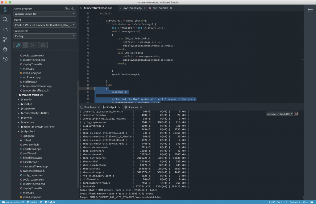
The temperatureThread listens for messages to be put into the queue. It then processes them by either increment/decrement of the setPoint or by setting an absolute setPoint.
Also, the queue wait will timeout every 200ms and when that happens it will read the temperature and update the display.
It will also send the cool, heat or off based on a +- 0.5 degree difference from the setPoint. In other words:
- temperatureF > setPoint + 0.5 = cool
- temperatureF < setPoint -0.5 = heat
- Otherwise OFF
void temperatureThread()
{

    char buffer[128];
    displaySendUpdateTemp(temperatureF);
    displaySendUpdateSetPoint(setPoint);

    while(1)
    {
        osEvent evt = queue.get(200);
        if (evt.status == osEventMessage) {
            msg_t *message = (msg_t*)evt.value.p;
            switch(message->cmd)
            {
                case CMD_setPointDelta:
                    setPoint += message->value;
                    displaySendSetPoint(setPoint);
                break;
                case CMD_setPoint:
                    setPoint = message->value;
                    displaySendUpdateSetPoint(setPoint);
                break;

            }
            mpool.free(message);

        }
        else
        {
            readTemp();

            // Control the HVAC system with +- 0.5 degree of Hystersis
            if(temperatureF < setPoint - 0.5)
                displaySendUpdateMode(-1.0);
            else if (temperatureF > setPoint + 0.5)
                displaySendUpdateMode(1.0);
            else
                displaySendUpdateMode(0.0);

            displaySendUpdateTemp(temperatureF);
        }
    }

}
The whole file (to make the copy/paste easier):
#include "mbed.h"
#include "temperatureThread.h"
#include "displayThread.h"

static float temperatureF;
static float setPoint = 75.0;

static void readTemp();

typedef enum {
    CMD_setPointDelta,
    CMD_setPoint,

} command_t;


typedef struct {
    command_t cmd;
    float    value;   /* AD result of measured voltage */
} msg_t;


static Queue<msg_t, 32> queue;
static MemoryPool<msg_t, 16> mpool;

void tempSendDeltaSetpointF(float delta)
{
    msg_t *message = mpool.alloc();
    if(message)
    {
        message->cmd = CMD_setPointDelta;
        message->value = delta;
        queue.put(message);
    }
}

void tempSendUpdateSetpointF(float setPoint)
{
    msg_t *message = mpool.alloc();
    if(message)
    {
        message->cmd = CMD_setPoint;
        message->value = setPoint;
        queue.put(message);
    }
}

void temperatureThread()
{

    char buffer[128];
    displaySendUpdateTemp(temperatureF);
    displaySendUpdateSetPoint(setPoint);

    while(1)
    {
        osEvent evt = queue.get(200);
        if (evt.status == osEventMessage) {
            msg_t *message = (msg_t*)evt.value.p;
            switch(message->cmd)
            {
                case CMD_setPointDelta:
                    setPoint += message->value;
                    displaySendUpdateSetPoint(setPoint);
                break;
                case CMD_setPoint:
                    setPoint = message->value;
                    displaySendUpdateSetPoint(setPoint);
                break;

            }
            mpool.free(message);

        }
        else
        {
            readTemp();

            // Control the HVAC system with +- 0.5 degree of Hystersis
            if(temperatureF < setPoint - 0.5)
                displaySendUpdateMode(-1.0);
            else if (temperatureF > setPoint + 0.5)
                displaySendUpdateMode(1.0);
            else
                displaySendUpdateMode(0.0);

            displaySendUpdateTemp(temperatureF);
        }
    }

}


static DigitalOut thermVDD(P10_3,1);
static DigitalOut thermGND(P10_0,0);
static AnalogIn thermOut(P10_1);

static void readTemp()
{
    float refVoltage = thermOut.read() * 2.4; // Range of ADC 0->2*Vref
    float refCurrent = refVoltage  / 10000.0; // 10k Reference Resistor
    float thermVoltage = 3.3 - refVoltage;    // Assume supply voltage is 3.3v
    float thermResistance = thermVoltage / refCurrent;
    float logrT = (float32_t)log((float64_t)thermResistance);

    /* Calculate temperature from the resistance of thermistor using Steinhart-Hart Equation */
    float stEqn = (float32_t)((0.0009032679) + ((0.000248772) * logrT) +
                             ((2.041094E-07) * pow((float64)logrT, (float32)3)));

    float temperatureC = (float32_t)(((1.0 / stEqn) - 273.15)  + 0.5);
    temperatureF = (temperatureC * 9.0/5.0) + 32;
}
Fix blinkThread.cpp
Now edit the blinkThread.cpp to remove the test code from Lesson 03:
#include "mbed.h"
#include "blinkThread.h"
#include "displayThread.h"

static DigitalOut led1(LED1);

void blinkThread()
{

    while (true)
    {
        led1 = !led1;
        displaySendUpdateTime();
        ThisThread::sleep_for(500);

    }
}
Update main.cpp
Then update main.cpp to start the new temperatureThread:
#include "mbed.h"
#include "blinkThread.h"
#include "displayThread.h"
#include "temperatureThread.h"

Thread blinkThreadHandle;
Thread displayThreadHandle;
Thread temperatureThreadHandle;

int main()
{

    printf("Started System\n");

    blinkThreadHandle.start(blinkThread);
    displayThreadHandle.start(displayThread);
    temperatureThreadHandle.start(temperatureThread);

}
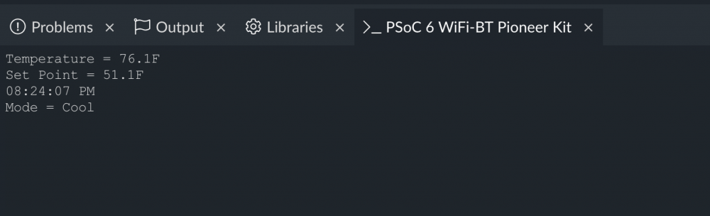
Build, Program and Test
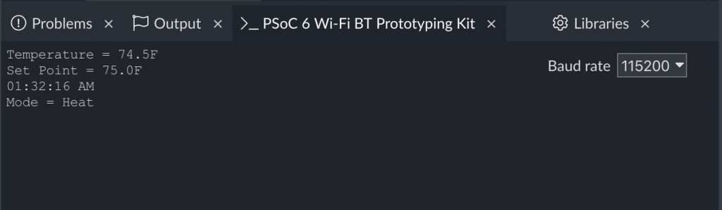
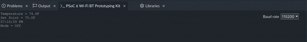
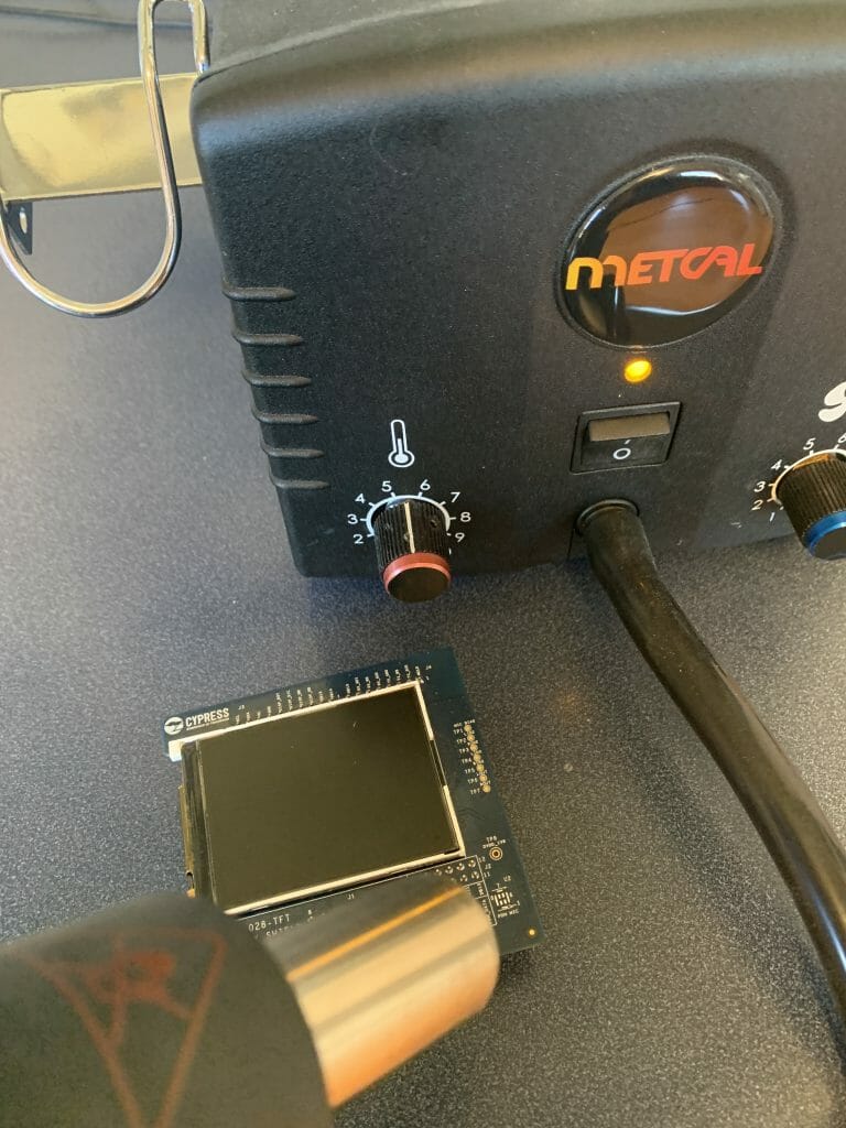
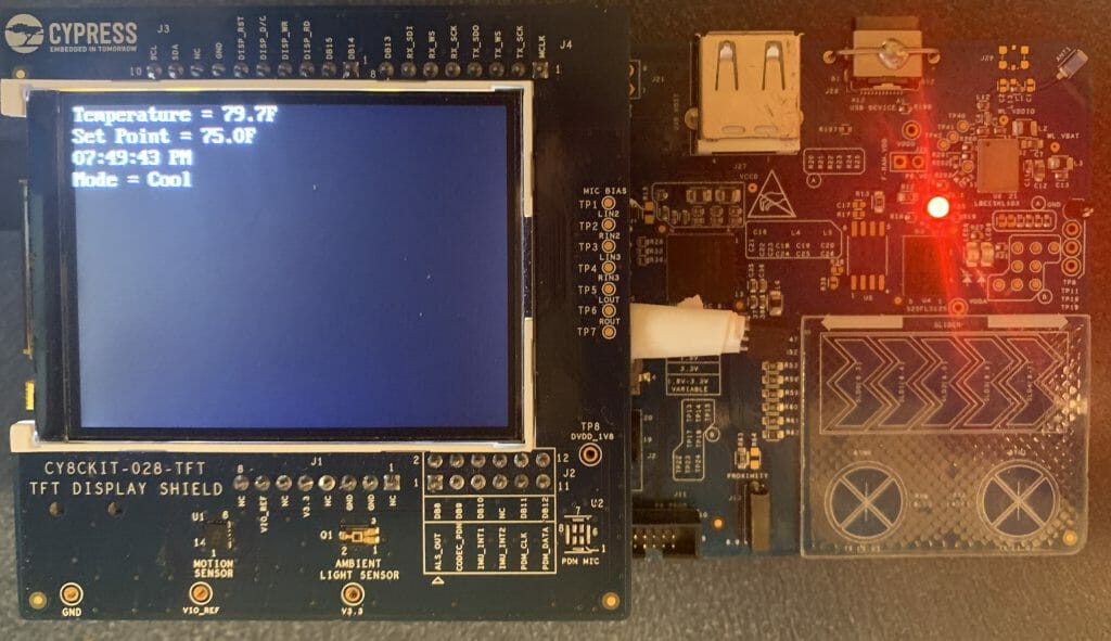
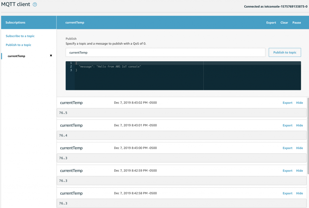
When you program the development kit you should be able to change the temperature by putting your finger on the thermistor:
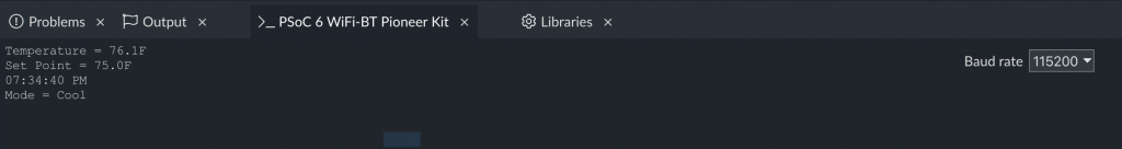
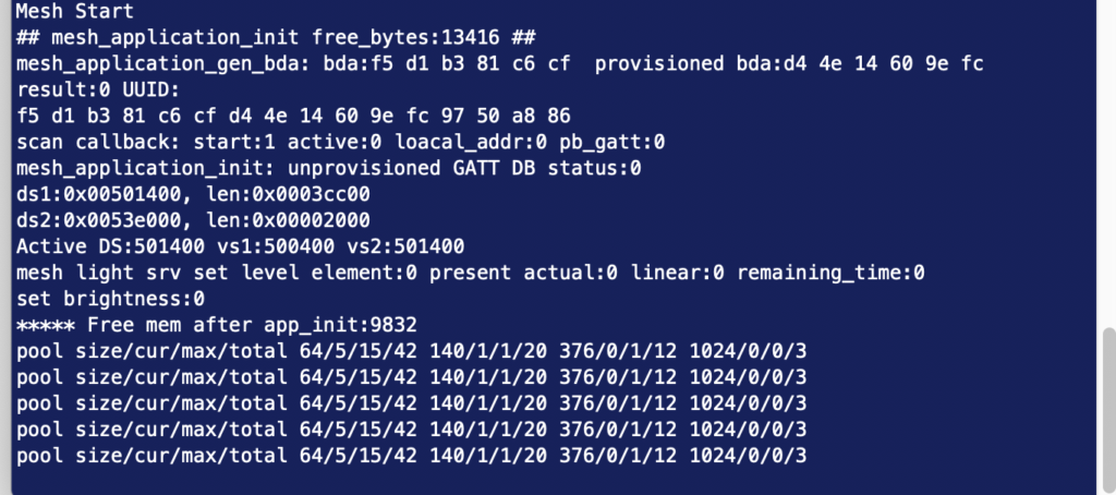
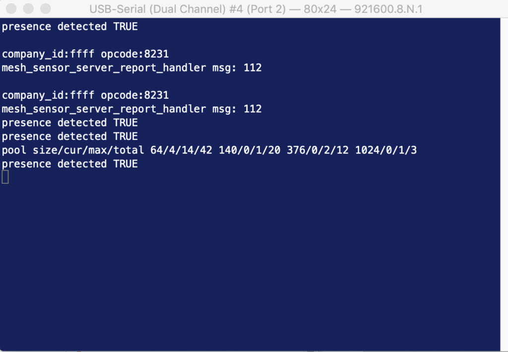
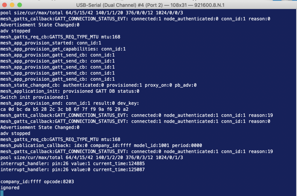
And your terminal should look something like this: