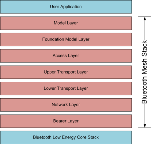
How To Design With Bluetooth Mesh
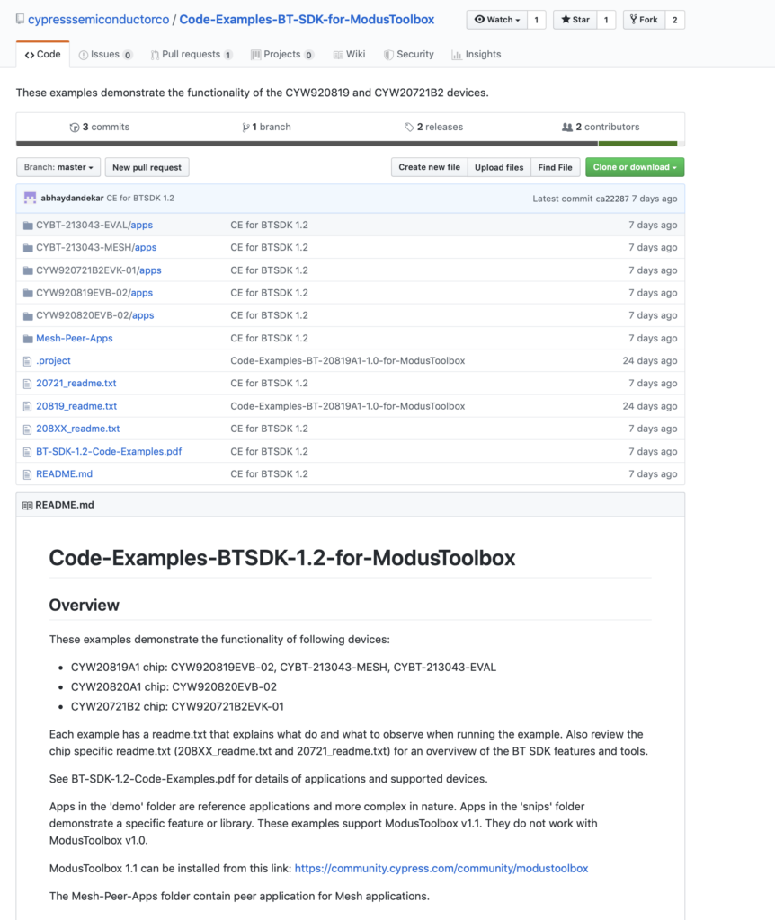
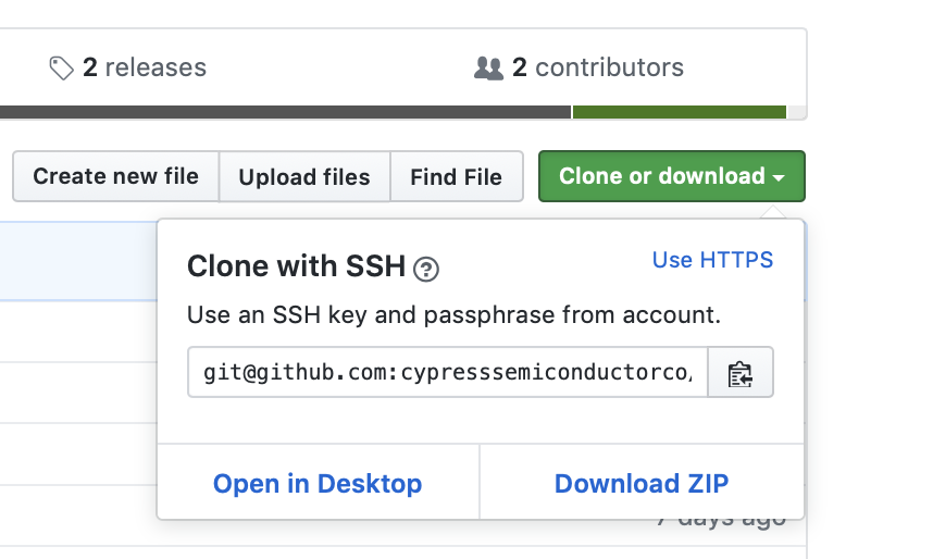
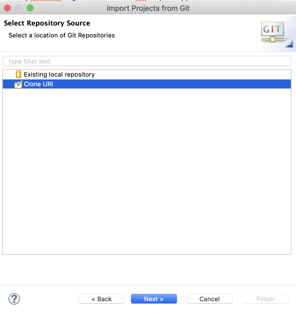
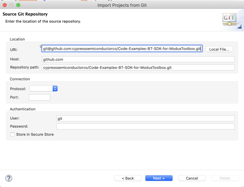
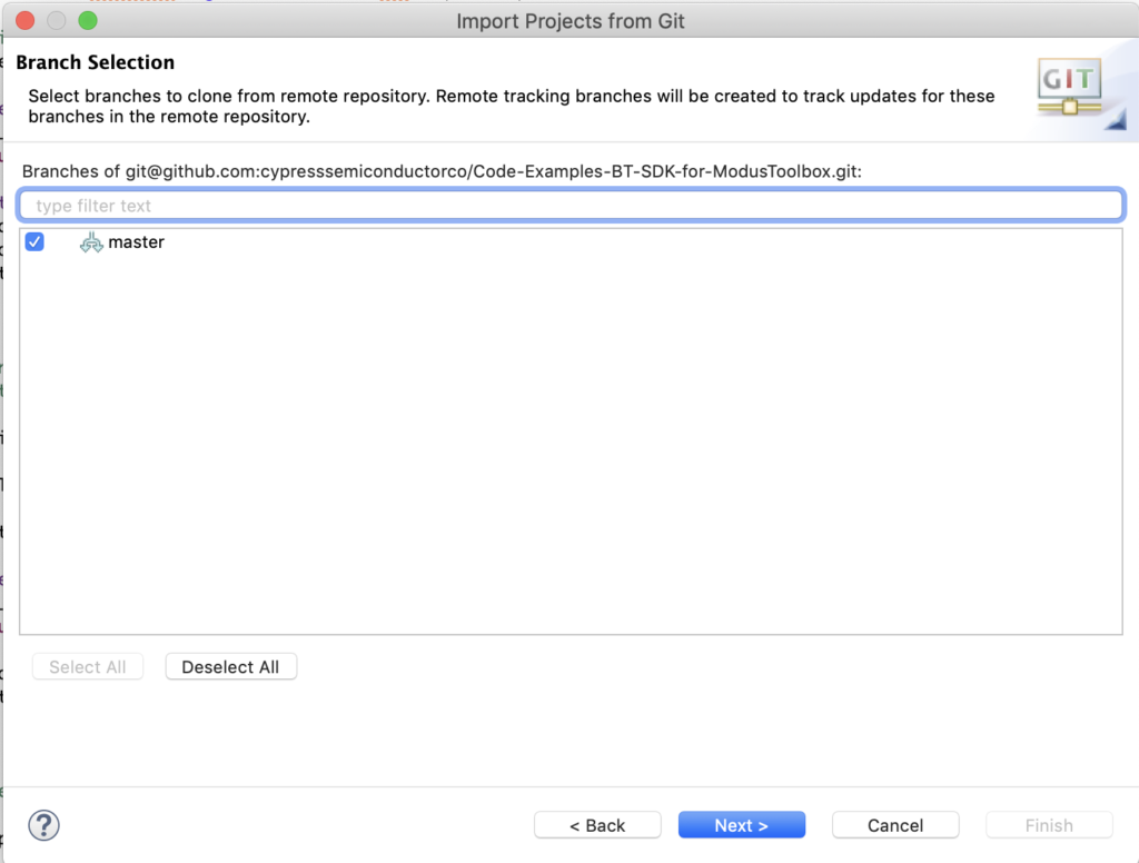
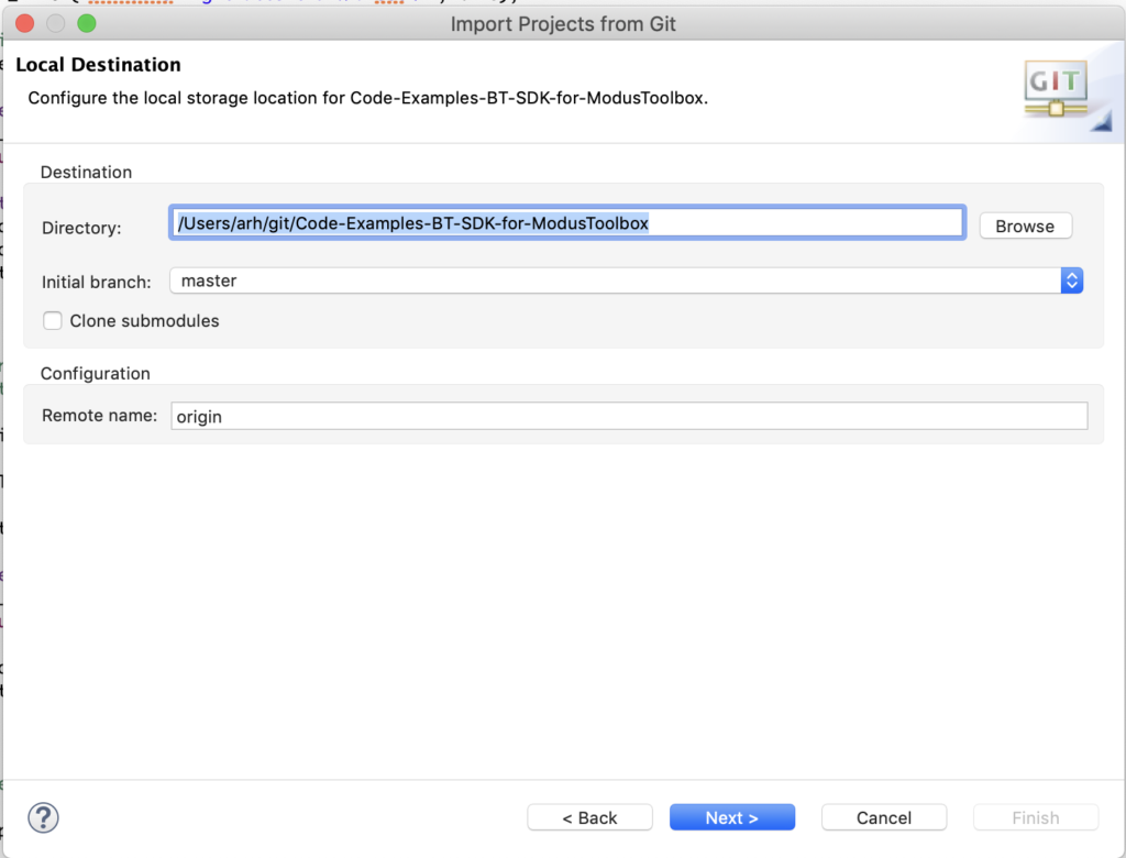
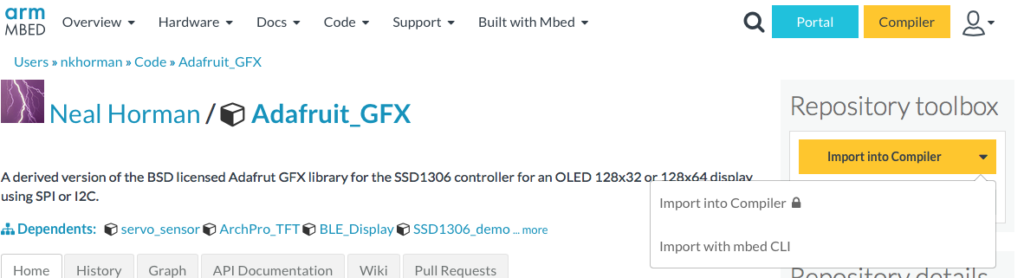
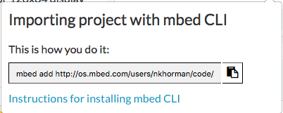
You can "git" a workspace will all of these files at https://github.com/iotexpert/MouserVTWBluetoothMesh or git@github.com:iotexpert/MouserVTWBluetoothMesh.git
Summary
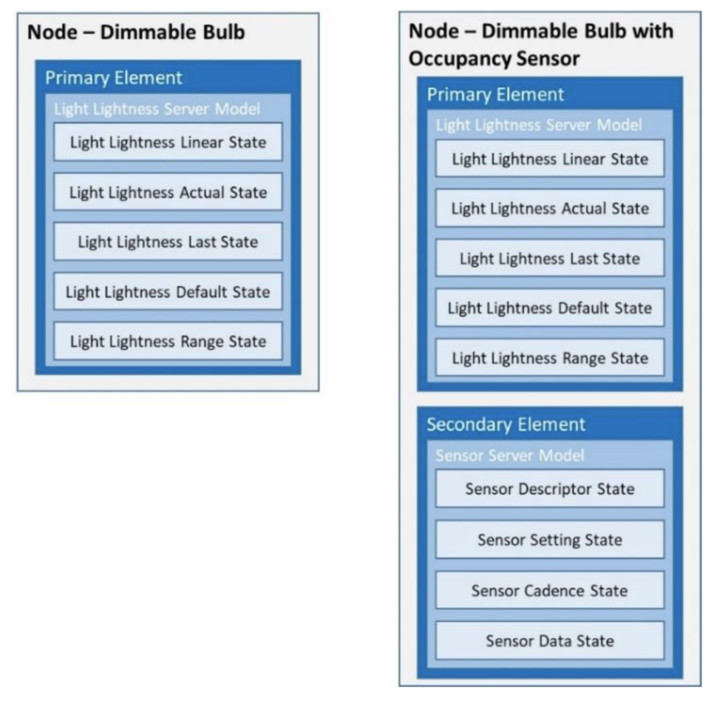
In this project I will create a Bluetooth Mesh Node that has two Light Lightness Server elements, one to control the red LED and one to control the Green LED. The purpose is to show an example adding elements to a node.
I will start with the BLE_Mesh_LightDimmable and then modify it to add the ability to control the Green LED as well.
To implement this lesson I will follow these steps:
- Make New Application with BLE_Mesh_LightDimmable Template
- Program it to make sure that things are still working
- Modify led_control.h to handle two LEDs
- Modify led_control.c to handle two LEDs
- Modify light_dimmable.c to update the Bluetooth Mesh Configuration
- Test
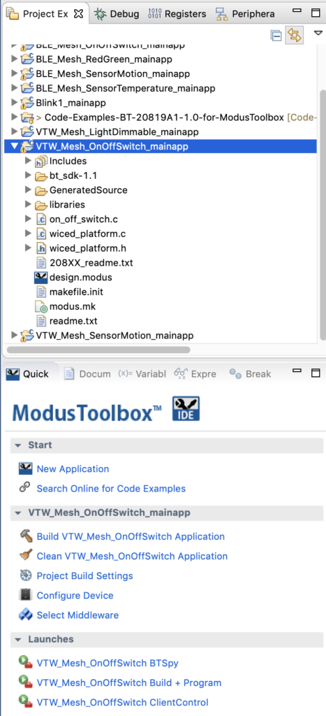
Make New Project with BLE_Mesh_LightDimmable Template
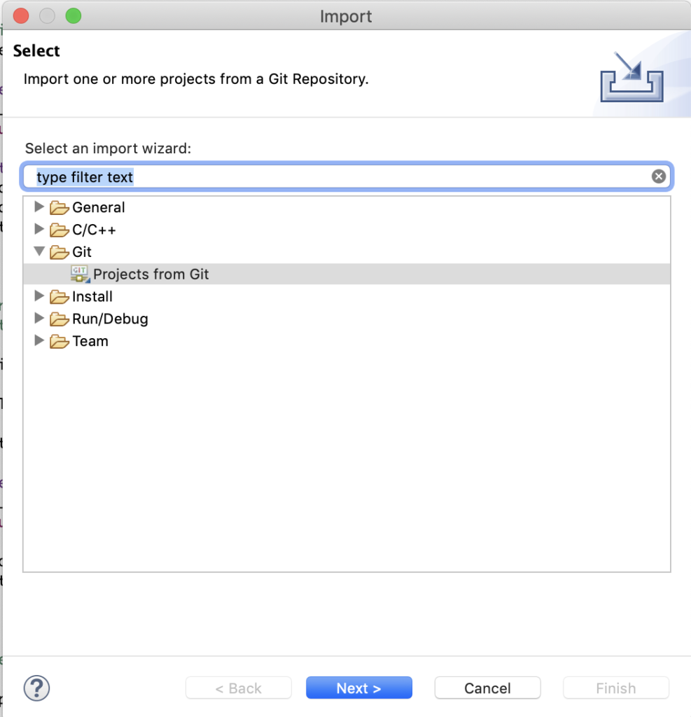
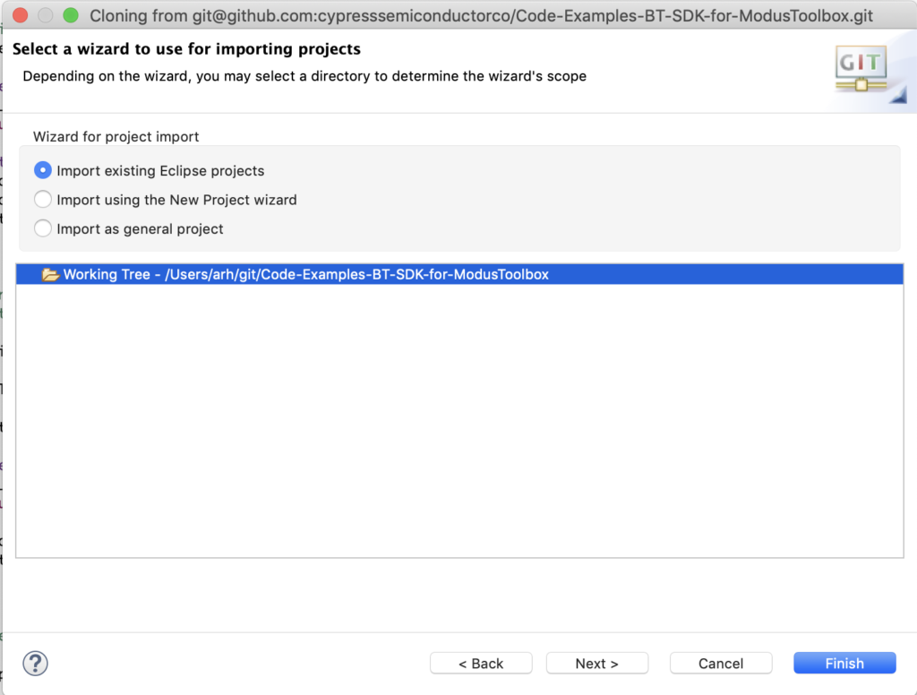
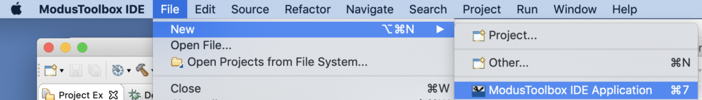
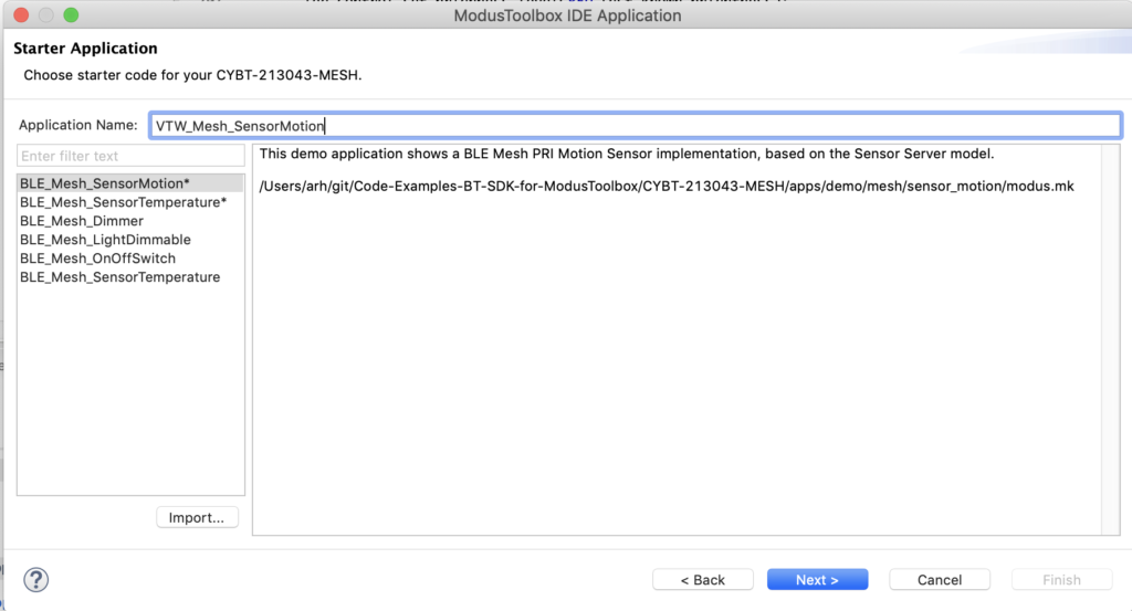
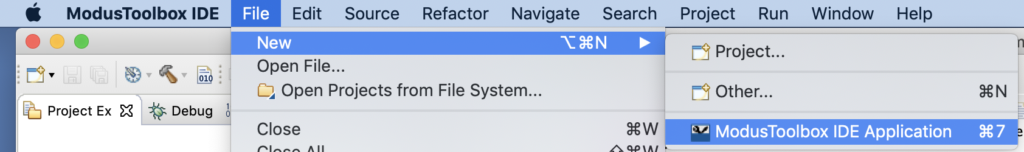
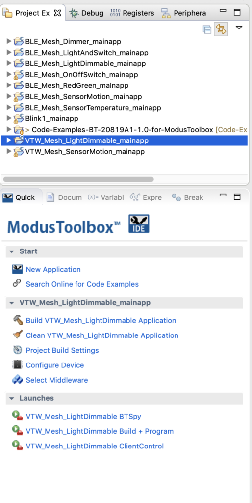
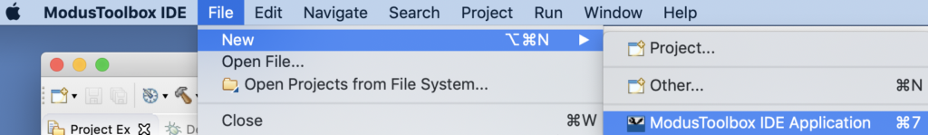
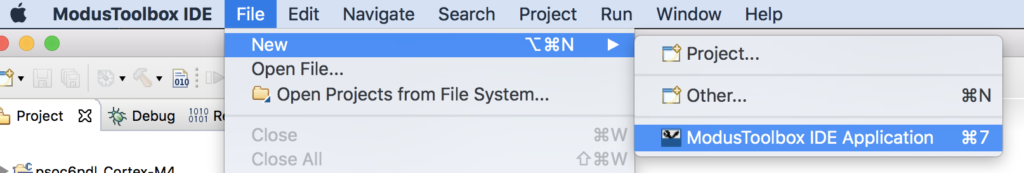
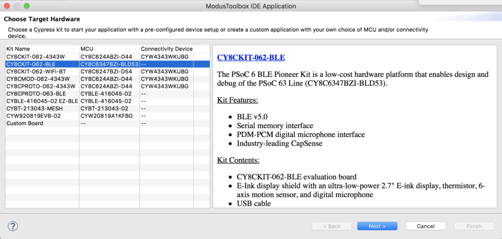
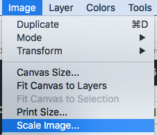
Use File->New->ModusToobox IDE Application

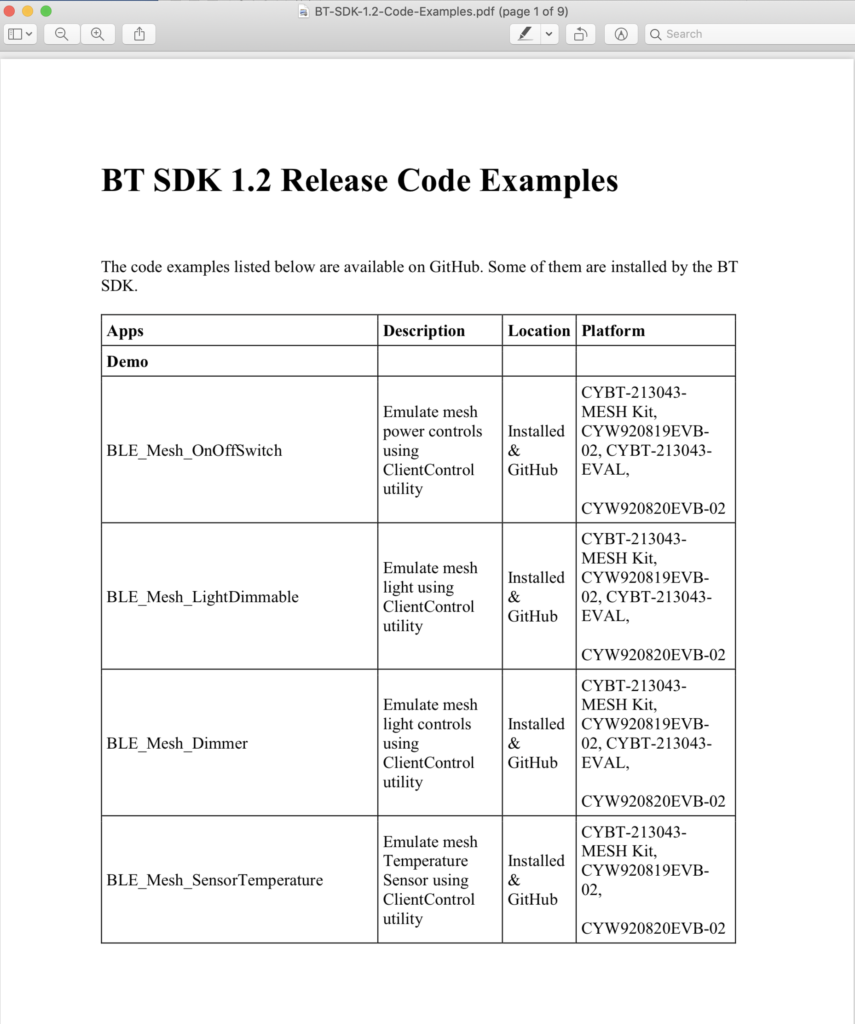
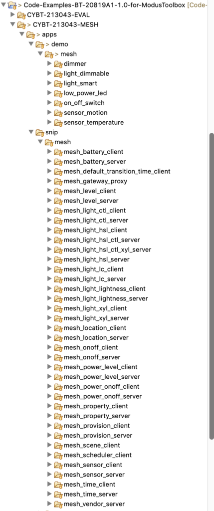
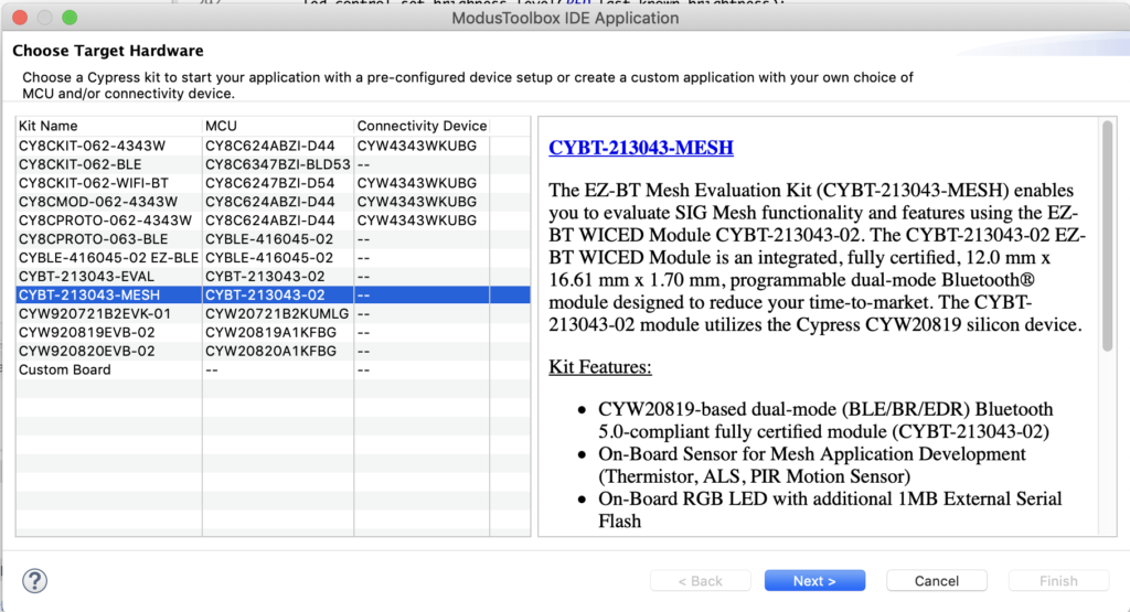
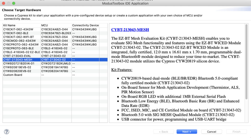
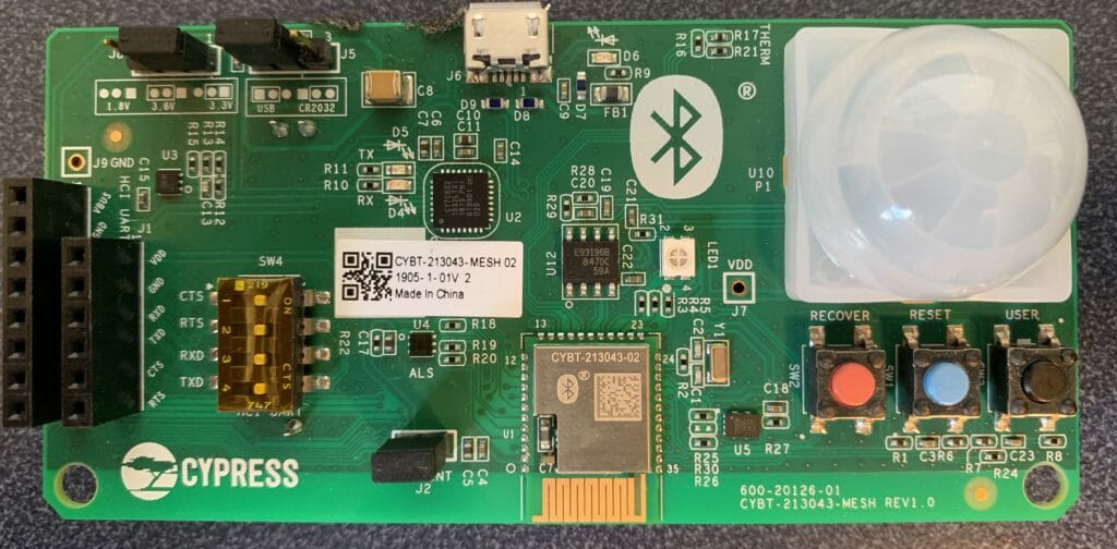
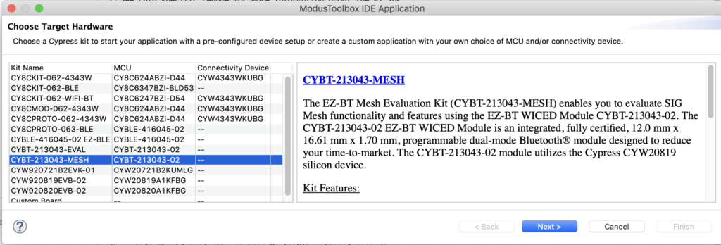
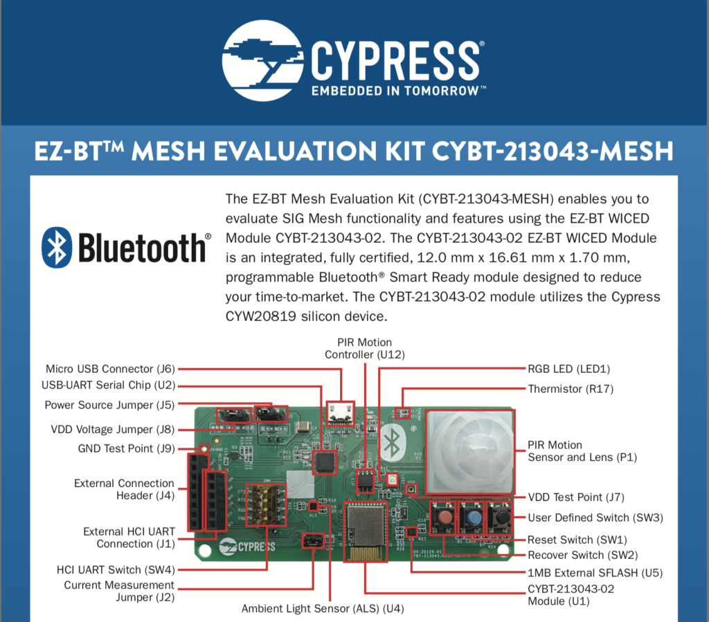
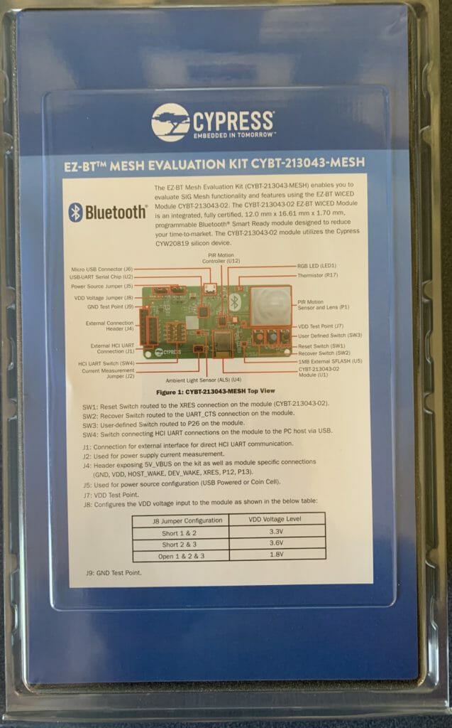
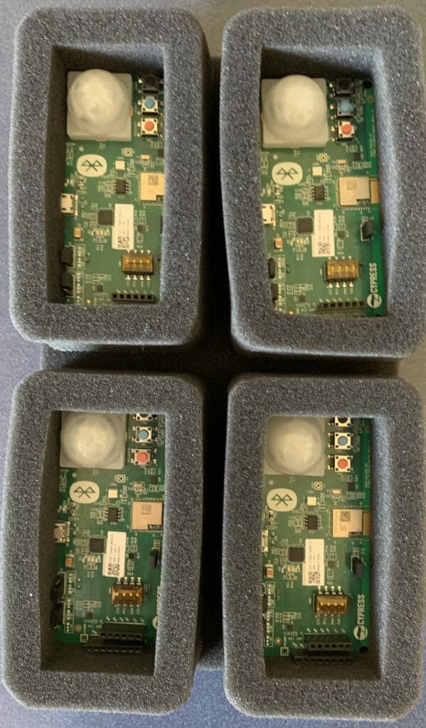
Pick the “CYBT-213043-MESH”
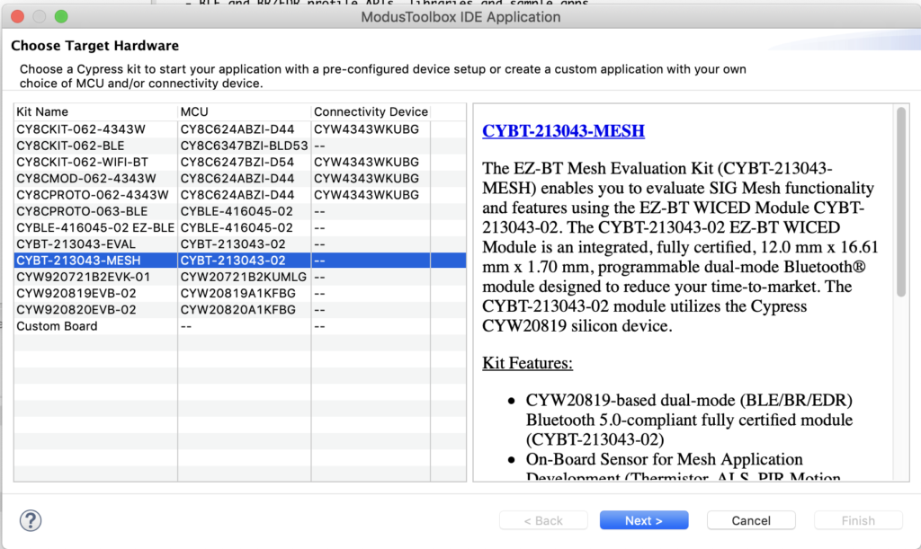
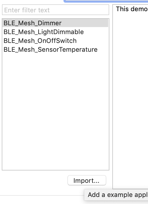
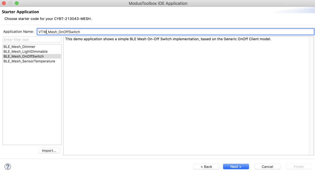
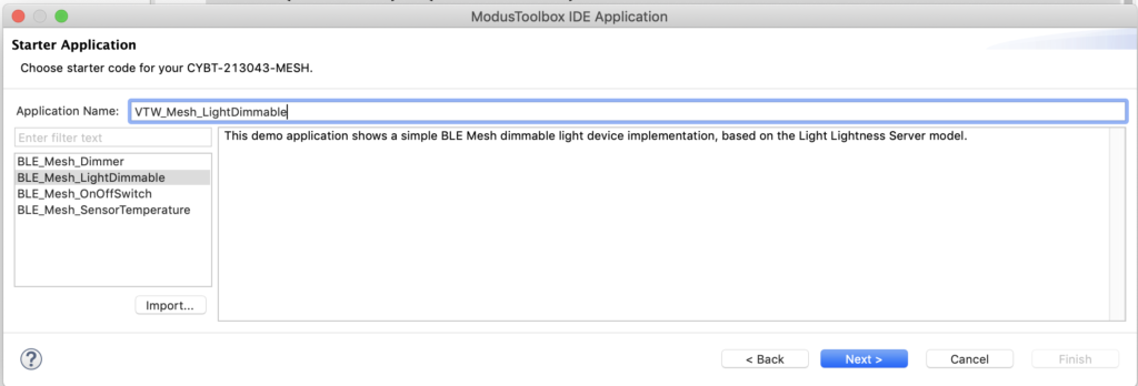
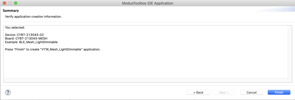
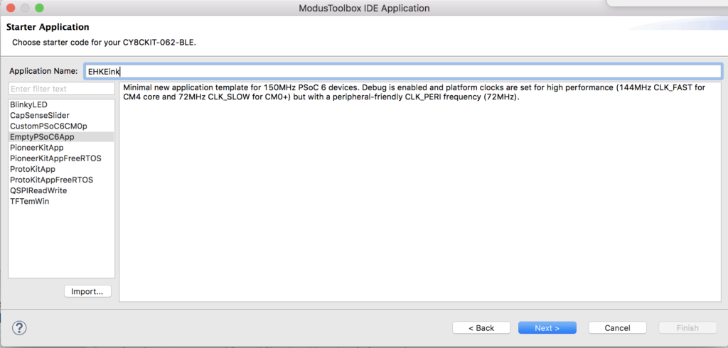
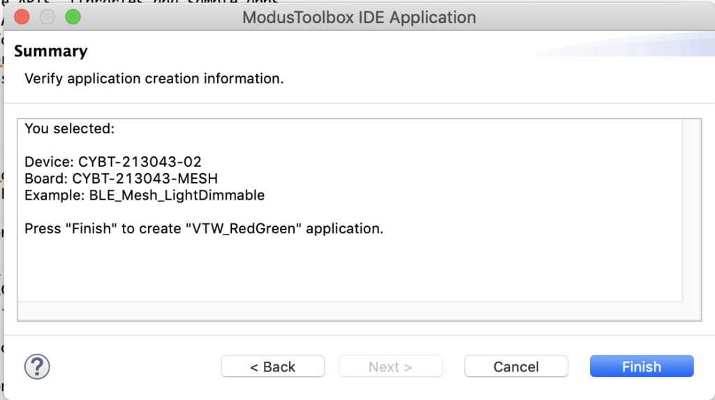
Choose “BLE_Mesh_LightDimmable” and name your project “VTW_RedGreen”
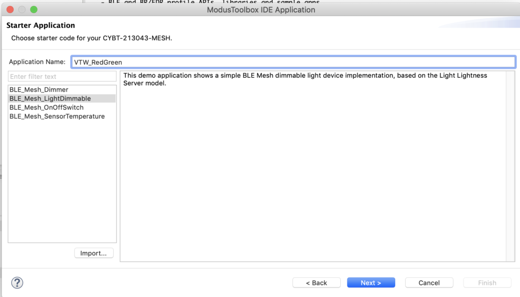
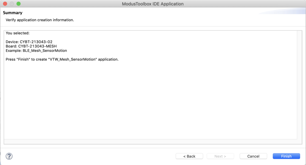
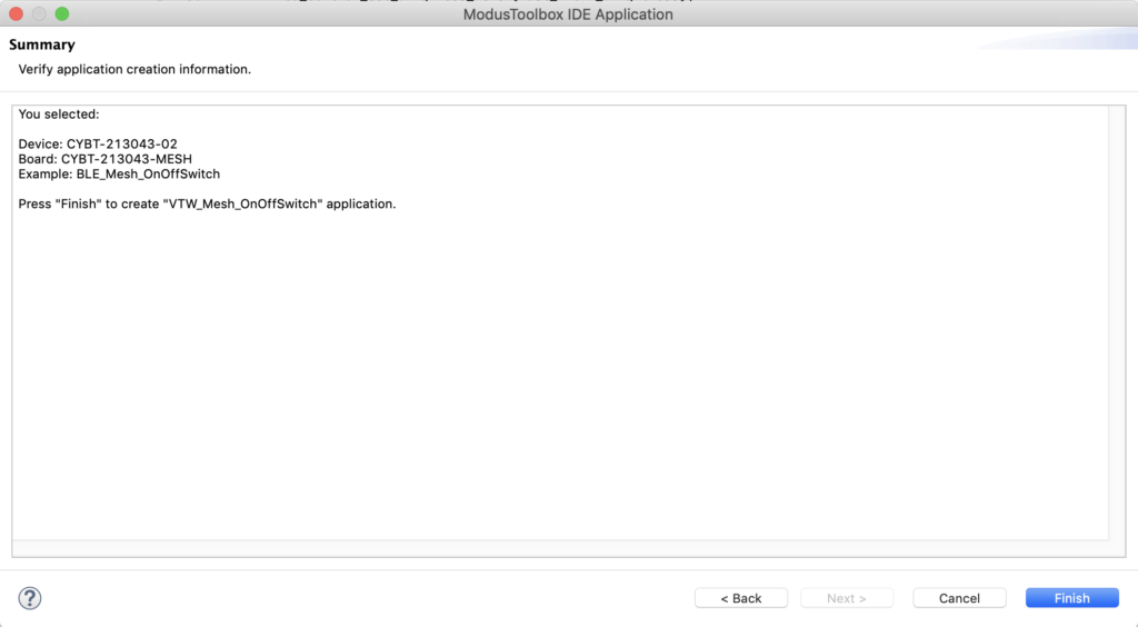
Click “Finish”
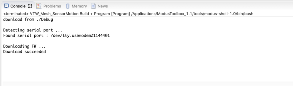
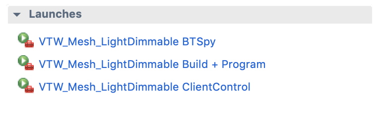
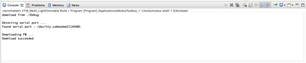
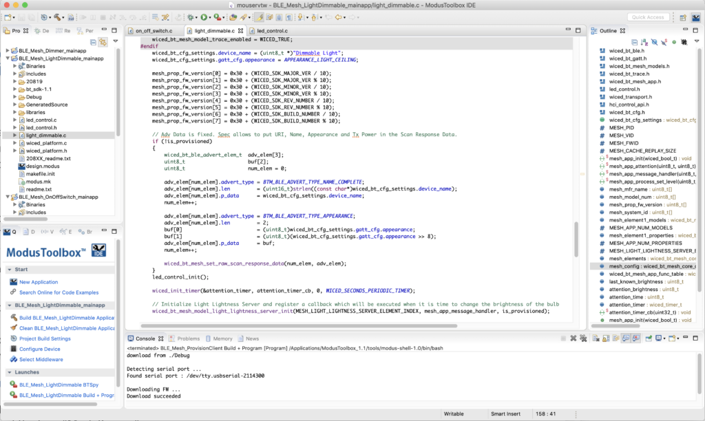
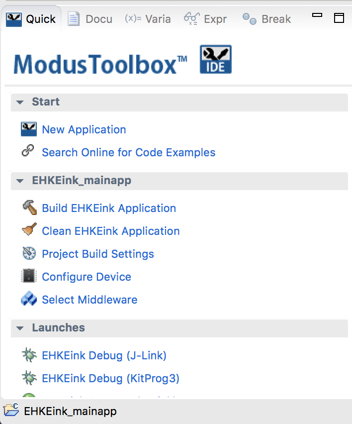
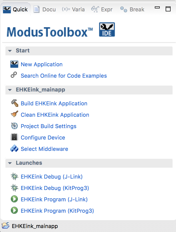
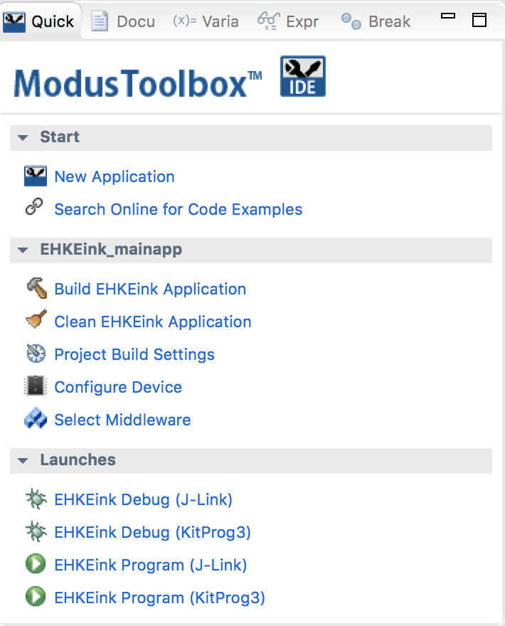
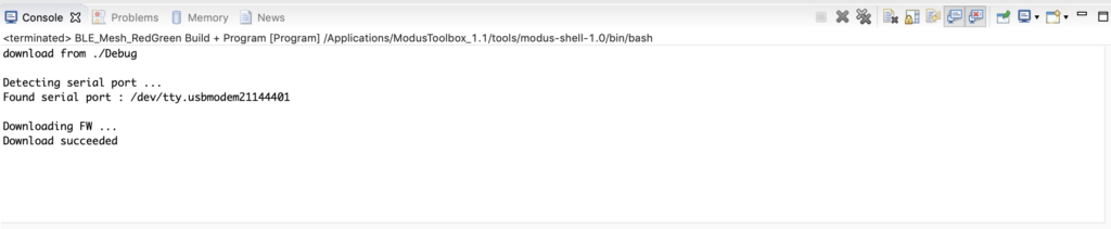
Program it to make sure that things are still working by clicking “Launches -> VTW_RedGreen Build + Program”
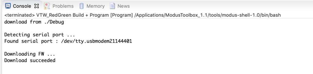
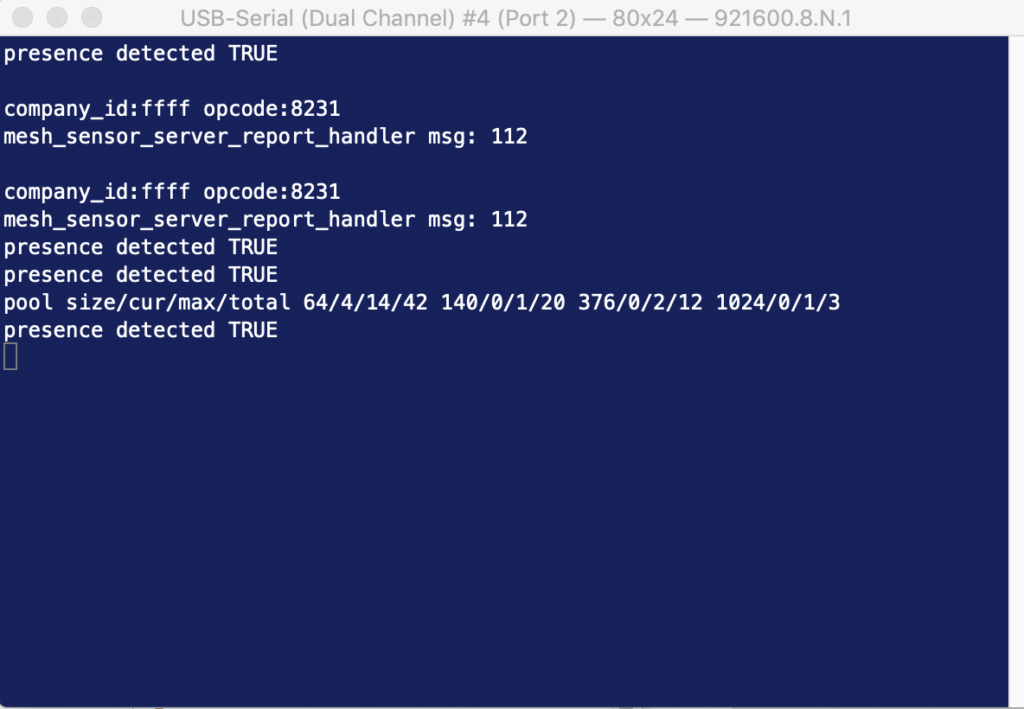
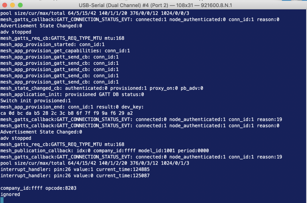
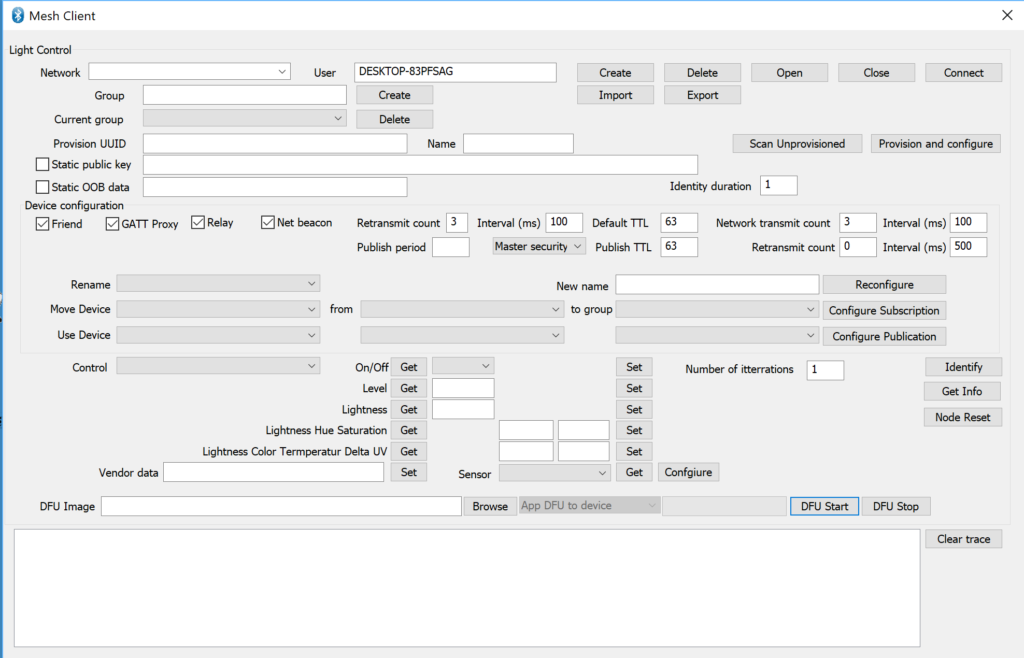
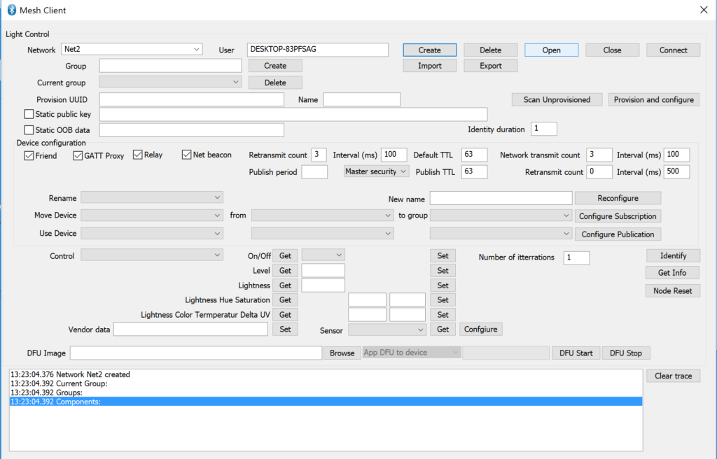
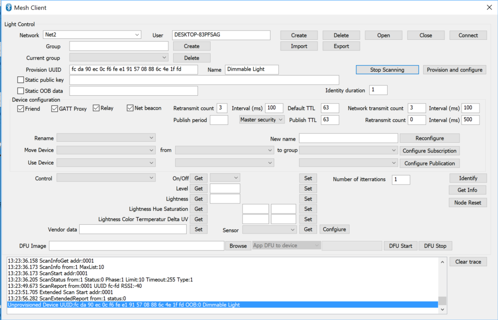
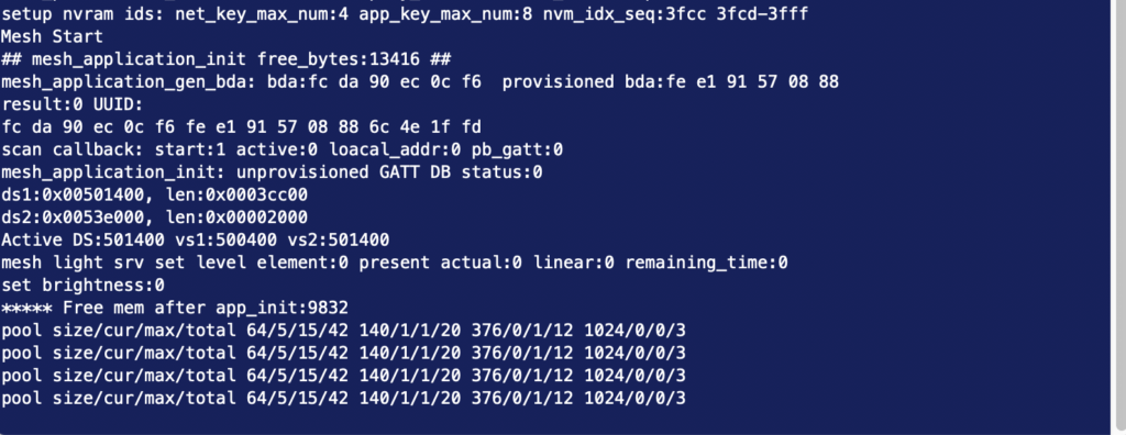
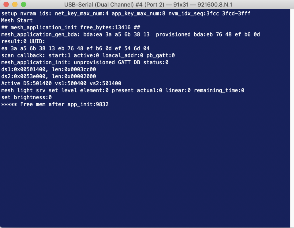
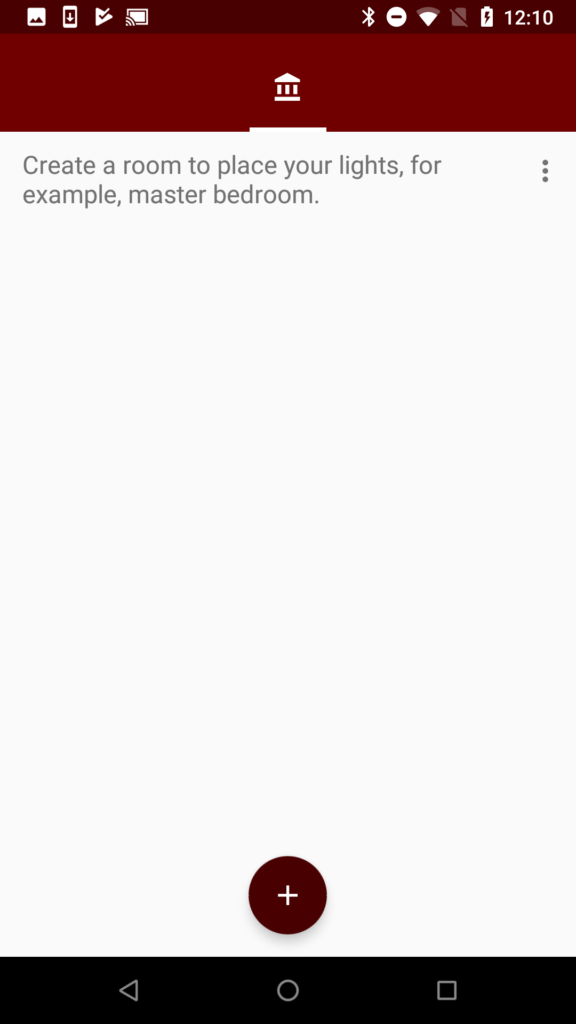
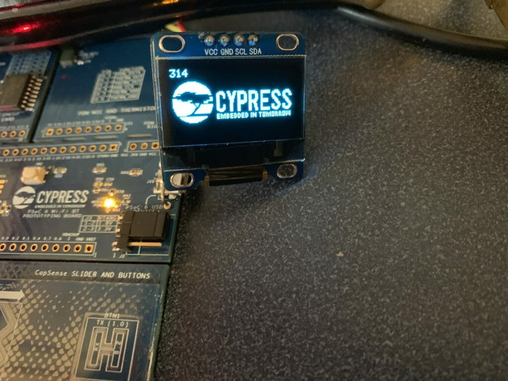
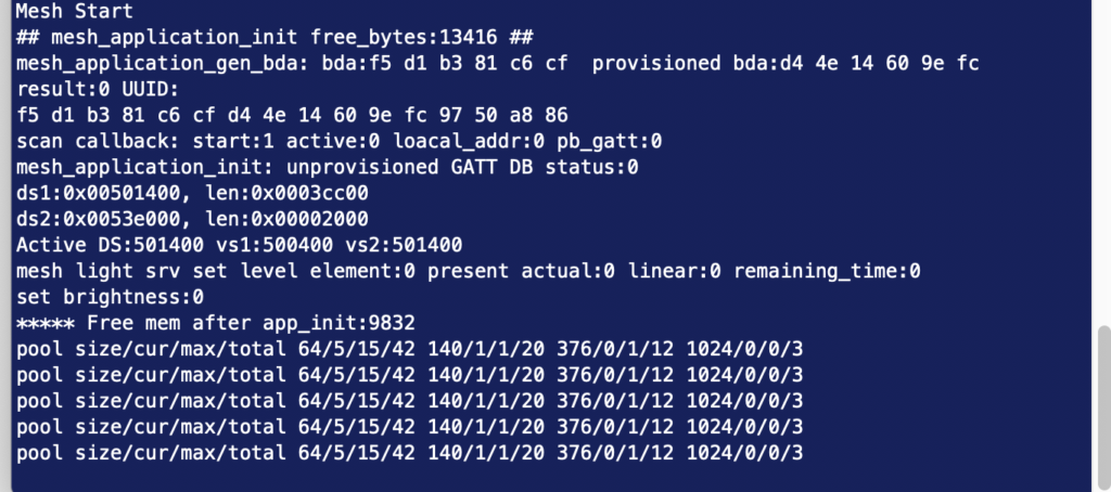
After it is downloaded you can see that it boots.
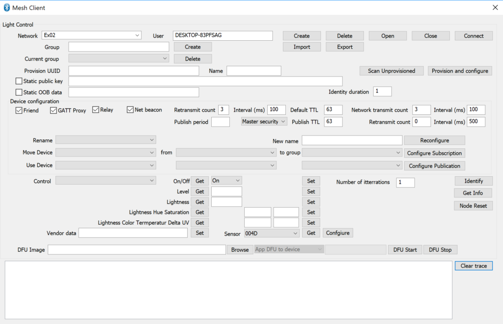
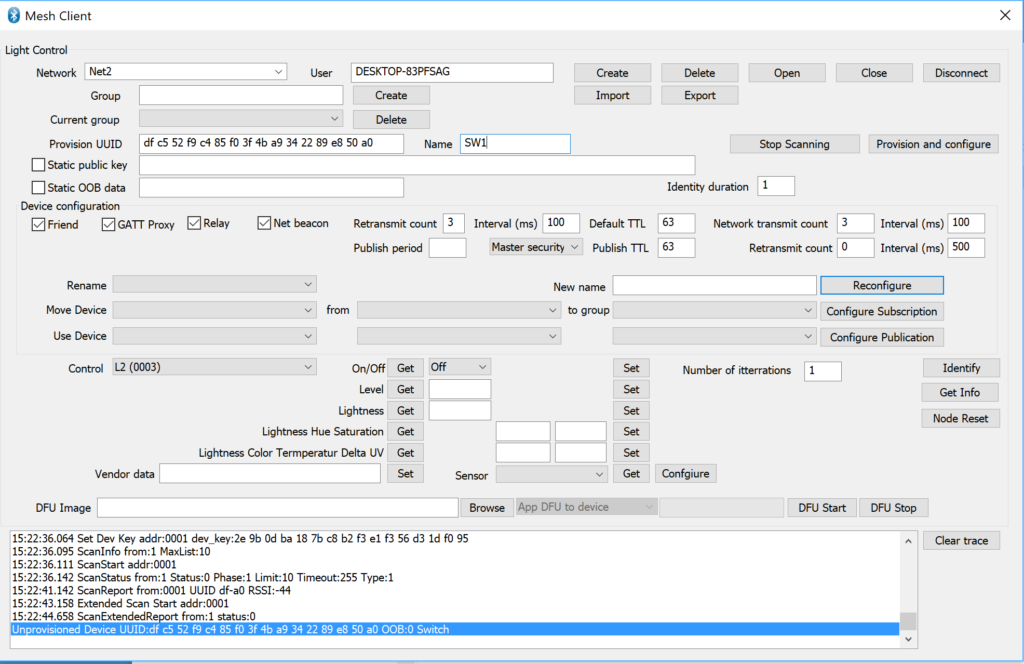
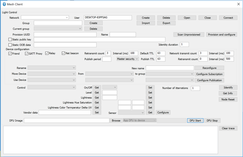
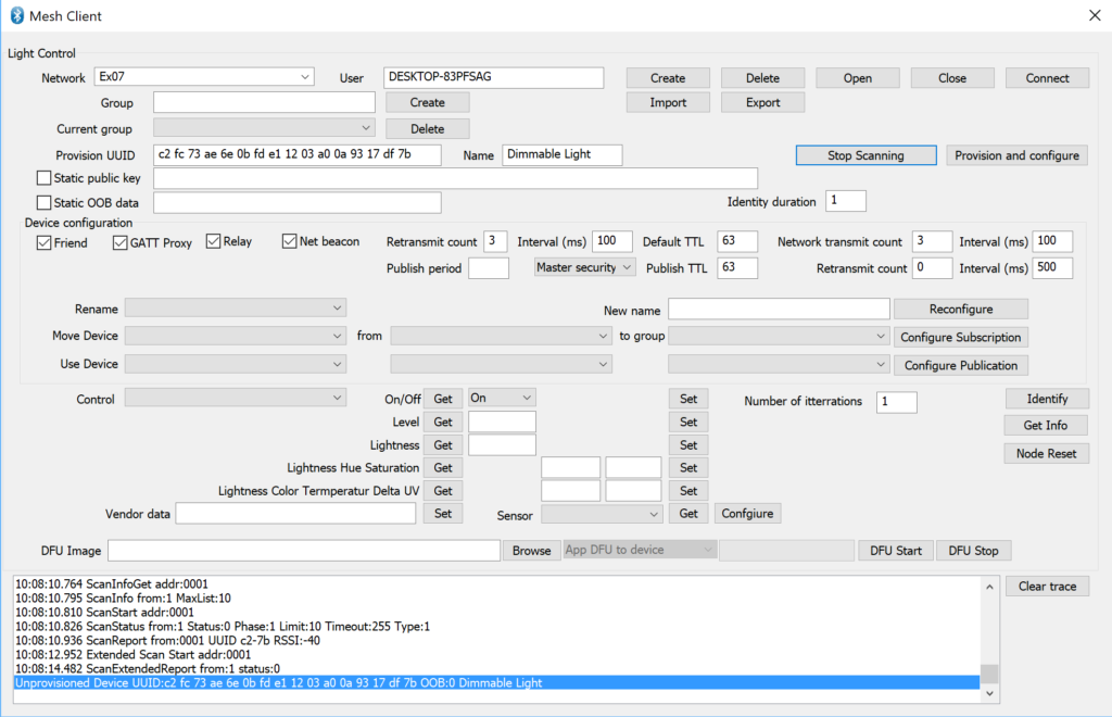
Press “Start Scan”. After a while you will see that it found the device.
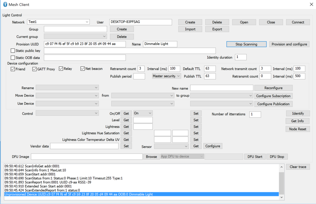
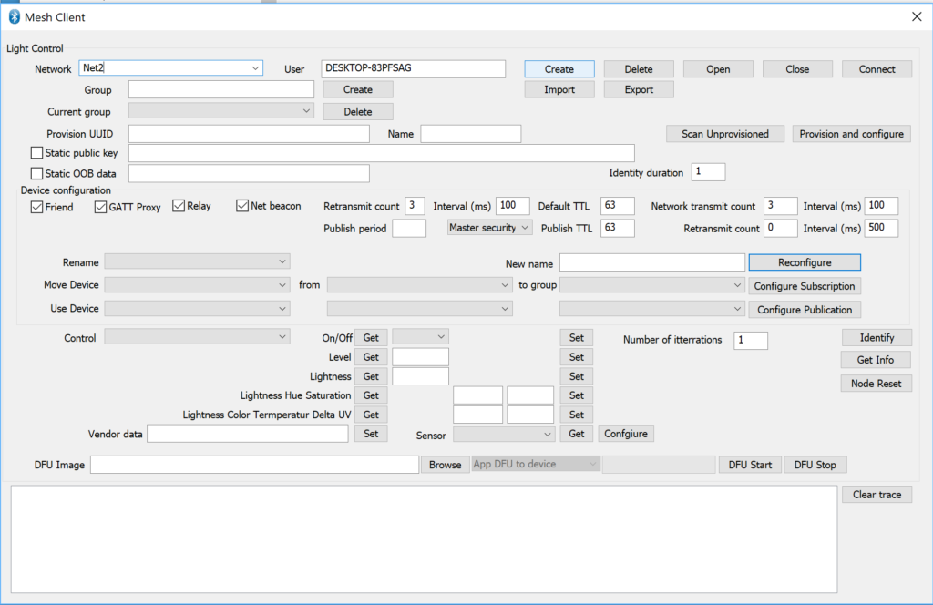
Now press “Provision and configure”
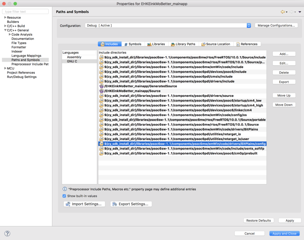
Modify led_control.h
The files led_control.h and .c are used to manage the LED. I will extend the led_control_set_brightness_level by adding the ability to control two LEDs – a Red and a Green
typedef enum {
	RED,
	GREEN,
} led_control_t;

void led_control_init(void);
void led_control_set_brighness_level(led_control_t whichLED, uint8_t brightness_level);
Modify led_control.c
Now I need to hook up a PWM to the Green LED. I will use PWM1 (notice that I also change the PWM_CHANNEL to _RED and _GREEN)
#define PWM_CHANNEL_RED           PWM0
#define PWM_CHANNEL_GREEN         PWM1
The led_control_init function is used to setup the hardware. Specifically to configure the two PWMs to be attached to the correct pins.
void led_control_init(void)
{
pwm_config_t pwm_config;
/* configure PWM */
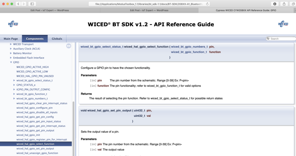
wiced_hal_gpio_select_function(WICED_GPIO_PIN_LED_2, WICED_PWM0);
wiced_hal_gpio_select_function(WICED_GPIO_PIN_LED_3, WICED_PWM1);
wiced_hal_aclk_enable(PWM_INP_CLK_IN_HZ, ACLK1, ACLK_FREQ_24_MHZ);
wiced_hal_pwm_get_params(PWM_INP_CLK_IN_HZ, 0, PWM_FREQ_IN_HZ, &pwm_config);
wiced_hal_pwm_start(PWM_CHANNEL_RED, PMU_CLK, pwm_config.toggle_count, pwm_config.init_count, 1);
wiced_hal_pwm_start(PWM_CHANNEL_GREEN, PMU_CLK, pwm_config.toggle_count, pwm_config.init_count, 1);
}
Finally, I modify the …set_brightness… function to handle Red and Green.
void led_control_set_brighness_level(led_control_t whichLED, uint8_t brightness_level)
{
    pwm_config_t pwm_config;

    WICED_BT_TRACE("set brightness:%d\n", brightness_level);

    // ToDo.  For some reason, setting brightness to 100% does not work well on 20719B1 platform. For now just use 99% instead of 100.
    if (brightness_level == 100)
        brightness_level = 99;

    wiced_hal_pwm_get_params(PWM_INP_CLK_IN_HZ, brightness_level, PWM_FREQ_IN_HZ, &pwm_config);
    switch(whichLED)
    {
    case RED:
        wiced_hal_pwm_change_values(PWM_CHANNEL_RED, pwm_config.toggle_count, pwm_config.init_count);

    break;
    case GREEN:
        wiced_hal_pwm_change_values(PWM_CHANNEL_GREEN, pwm_config.toggle_count, pwm_config.init_count);

    	break;
    }
}
Modify light_dimmable.c
Now I need to add a new element to the mesh_elements array. Before I can do that, it need to create new element array called “mesh_element2_models” with the model that I need. Notice that I also change the original code to have _RED
wiced_bt_mesh_core_config_model_t   mesh_element1_models[] =
{
    WICED_BT_MESH_DEVICE,
    WICED_BT_MESH_MODEL_USER_PROPERTY_SERVER,
    WICED_BT_MESH_MODEL_LIGHT_LIGHTNESS_SERVER,
};
#define MESH_APP_NUM_MODELS_RED  (sizeof(mesh_element1_models) / sizeof(wiced_bt_mesh_core_config_model_t))


wiced_bt_mesh_core_config_property_t mesh_element1_properties[] =
{
    {
        .id          = WICED_BT_MESH_PROPERTY_DEVICE_FIRMWARE_REVISION,
        .type        = WICED_BT_MESH_PROPERTY_TYPE_USER,
        .user_access = WICED_BT_MESH_PROPERTY_ID_READABLE,
        .max_len     = WICED_BT_MESH_PROPERTY_LEN_DEVICE_FIRMWARE_REVISION,
        .value       = mesh_prop_fw_version
    },
};
#define MESH_APP_NUM_PROPERTIES (sizeof(mesh_element1_properties) / sizeof(wiced_bt_mesh_core_config_property_t))

wiced_bt_mesh_core_config_model_t   mesh_element2_models[] =
{
    WICED_BT_MESH_MODEL_LIGHT_LIGHTNESS_SERVER,
};
#define MESH_APP_NUM_MODELS_GREEN  (sizeof(mesh_element2_models) / sizeof(wiced_bt_mesh_core_config_model_t))

#define MESH_LIGHT_LIGHTNESS_SERVER_ELEMENT_INDEX_RED   0
#define MESH_LIGHT_LIGHTNESS_SERVER_ELEMENT_INDEX_GREEN   1

wiced_bt_mesh_core_config_element_t mesh_elements[] =
{
    {
        .location = MESH_ELEM_LOC_MAIN,                                 // location description as defined in the GATT Bluetooth Namespace Descriptors section of the Bluetooth SIG Assigned Numbers
        .default_transition_time = MESH_DEFAULT_TRANSITION_TIME_IN_MS,  // Default transition time for models of the element in milliseconds
        .onpowerup_state = WICED_BT_MESH_ON_POWER_UP_STATE_RESTORE,     // Default element behavior on power up
        .default_level = 0,                                             // Default value of the variable controlled on this element (for example power, lightness, temperature, hue...)
        .range_min = 1,                                                 // Minimum value of the variable controlled on this element (for example power, lightness, temperature, hue...)
        .range_max = 0xffff,                                            // Maximum value of the variable controlled on this element (for example power, lightness, temperature, hue...)
        .move_rollover = 0,                                             // If true when level gets to range_max during move operation, it switches to min, otherwise move stops.
        .properties_num = MESH_APP_NUM_PROPERTIES,                      // Number of properties in the array models
        .properties = mesh_element1_properties,                         // Array of properties in the element.
        .sensors_num = 0,                                               // Number of sensors in the sensor array
        .sensors = NULL,                                                // Array of sensors of that element
        .models_num = MESH_APP_NUM_MODELS_RED,                          // Number of models in the array models
        .models = mesh_element1_models,                                 // Array of models located in that element. Model data is defined by structure wiced_bt_mesh_core_config_model_t
    },
    {
        .location = MESH_ELEM_LOC_MAIN,                                 // location description as defined in the GATT Bluetooth Namespace Descriptors section of the Bluetooth SIG Assigned Numbers
        .default_transition_time = MESH_DEFAULT_TRANSITION_TIME_IN_MS,  // Default transition time for models of the element in milliseconds
        .onpowerup_state = WICED_BT_MESH_ON_POWER_UP_STATE_RESTORE,     // Default element behavior on power up
        .default_level = 0,                                             // Default value of the variable controlled on this element (for example power, lightness, temperature, hue...)
        .range_min = 1,                                                 // Minimum value of the variable controlled on this element (for example power, lightness, temperature, hue...)
        .range_max = 0xffff,                                            // Maximum value of the variable controlled on this element (for example power, lightness, temperature, hue...)
        .move_rollover = 0,                                             // If true when level gets to range_max during move operation, it switches to min, otherwise move stops.
        .properties_num = 0,                                            // Number of properties in the array models
        .properties = NULL,                                             // Array of properties in the element.
        .sensors_num = 0,                                               // Number of sensors in the sensor array
        .sensors = NULL,                                                // Array of sensors of that element
        .models_num = MESH_APP_NUM_MODELS_GREEN,                              // Number of models in the array models
        .models = mesh_element2_models,                                 // Array of models located in that element. Model data is defined by structure wiced_bt_mesh_core_config_model_t
    },

};
In the mesh_app_init function you need to initialize the new light lightness server model. We will use the same message handler for both light lightness server models.
wiced_bt_mesh_model_light_lightness_server_init(MESH_LIGHT_LIGHTNESS_SERVER_ELEMENT_INDEX_GREEN, mesh_app_message_handler, is_provisioned);
Search and replace all of the “led_control_set_brighness_level(attention_brightness);” to be “led_control_set_brighness_level(RED,attention_brightness);”
The last step is to update the mesh_app_process_set_level callback to handle the two cases.
/*
 * Command from the level client is received to set the new level
 */
void mesh_app_process_set_level(uint8_t element_idx, wiced_bt_mesh_light_lightness_status_t *p_status)
{
    WICED_BT_TRACE("mesh light srv set level element:%d present actual:%d linear:%d remaining_time:%d\n",
        element_idx, p_status->lightness_actual_present, p_status->lightness_linear_present, p_status->remaining_time);

    last_known_brightness = (uint8_t)((uint32_t)p_status->lightness_actual_present * 100 / 65535);
    if(element_idx == MESH_LIGHT_LIGHTNESS_SERVER_ELEMENT_INDEX_RED)
    		led_control_set_brighness_level(RED,last_known_brightness);

    if(element_idx == MESH_LIGHT_LIGHTNESS_SERVER_ELEMENT_INDEX_GREEN)
    		led_control_set_brighness_level(GREEN,last_known_brightness);

    // If we were alerting user, stop it.
    wiced_stop_timer(&attention_timer);
}
Test
Do a “Node Reset” to remove the old node from the network. It doesn’t really matter… but I find it less confusing to have it gone.
Program the kit using the launch “VTW_RedGreen Build + Program”
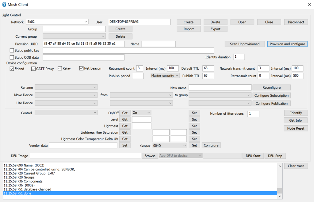
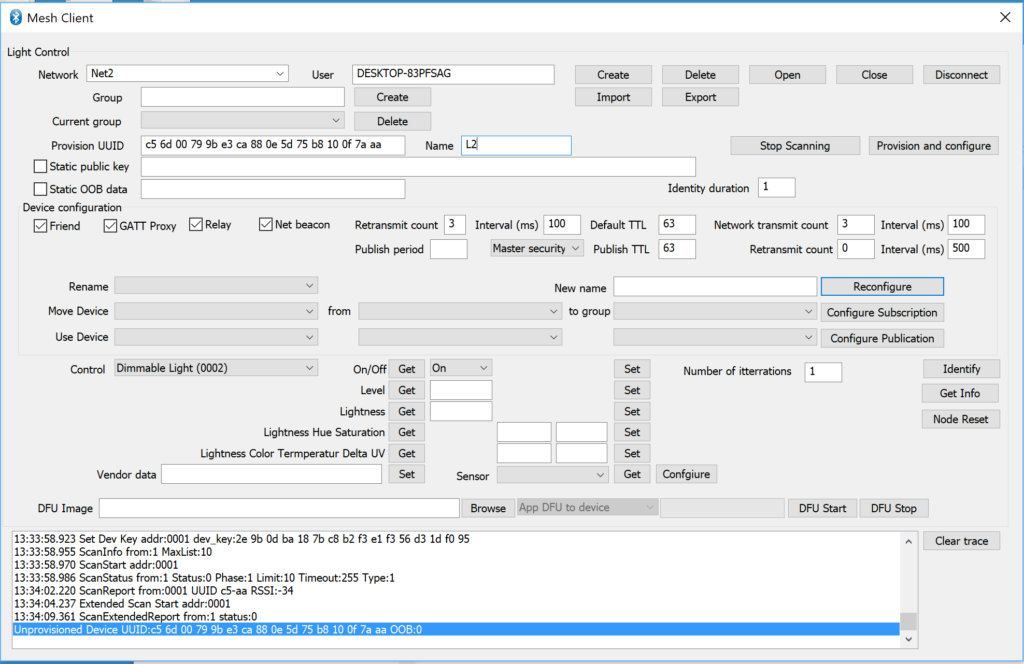
Press “Scan Unprovisioned”
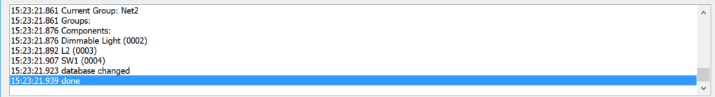
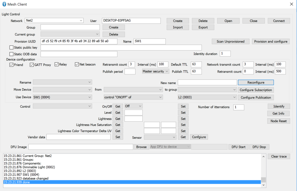
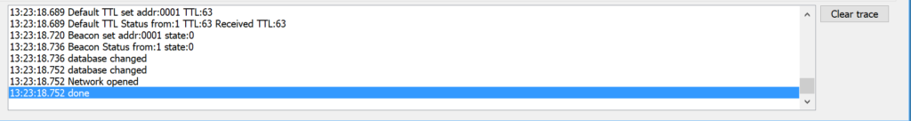
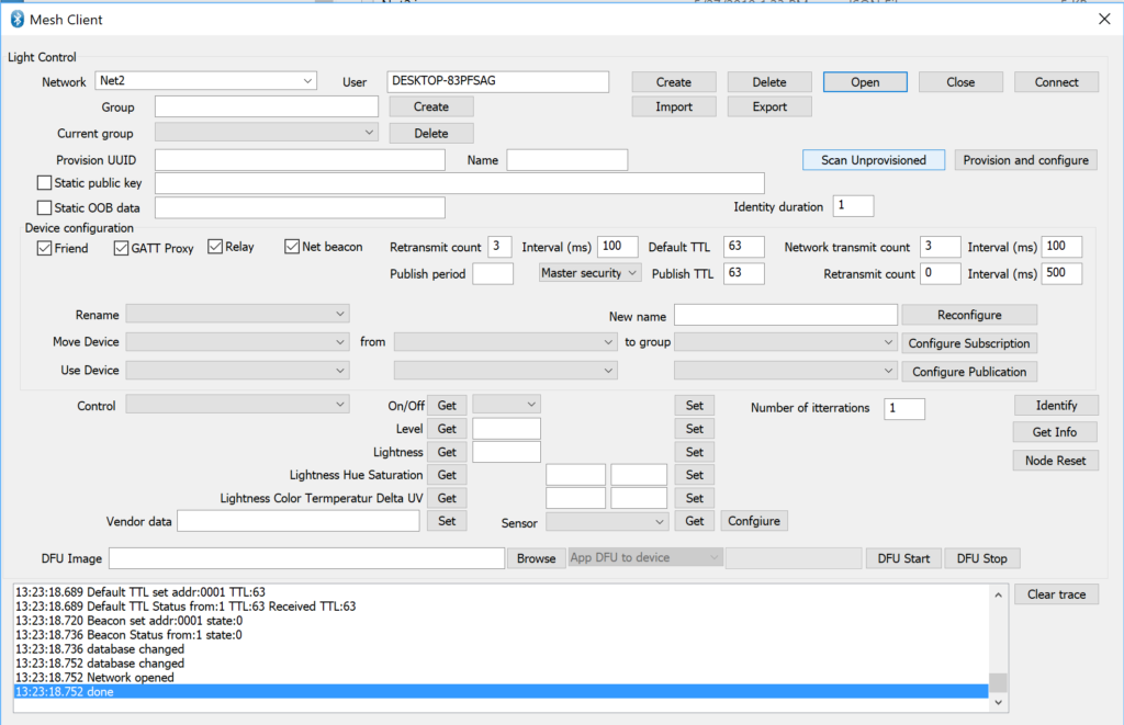
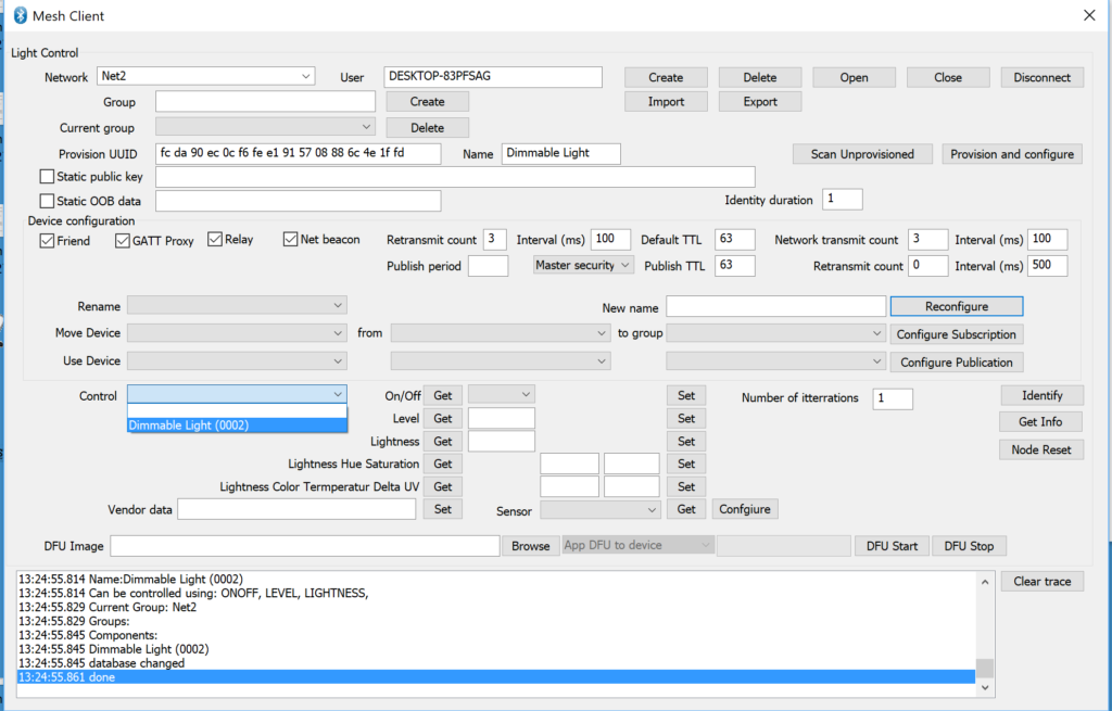
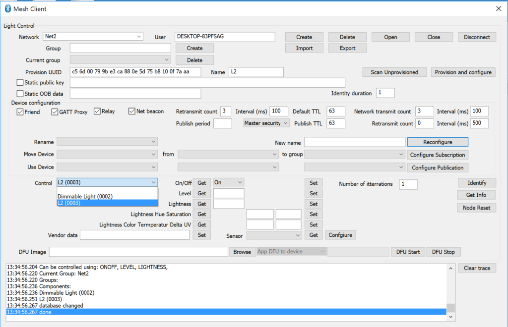
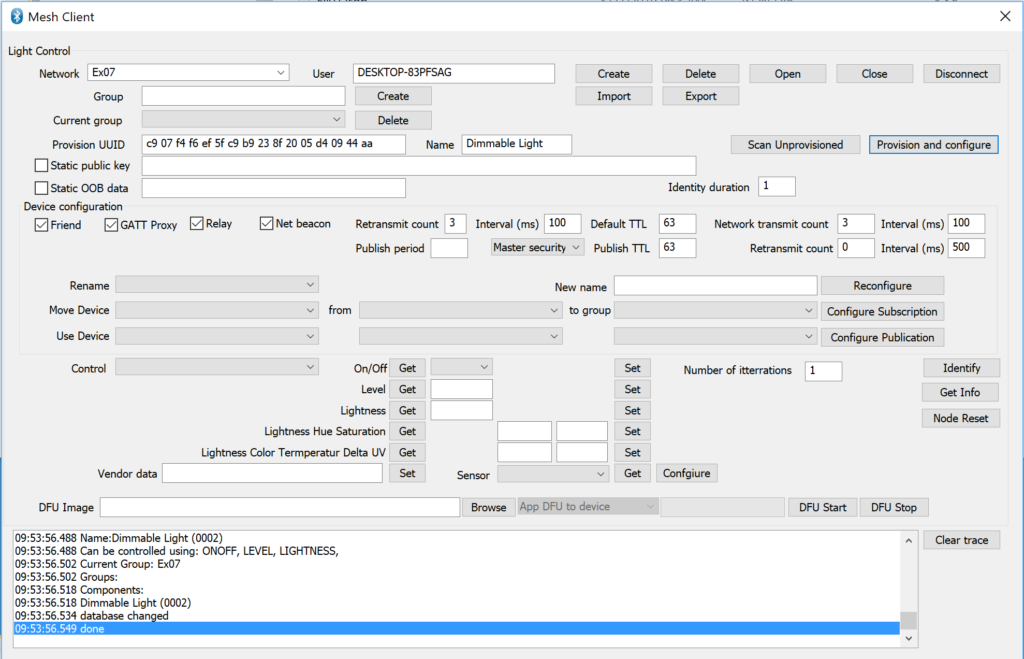
Press “Provision and configure”. It takes a minute. When it is done you will see “…done” in the trace window.
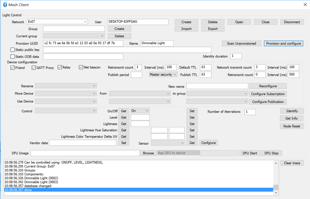
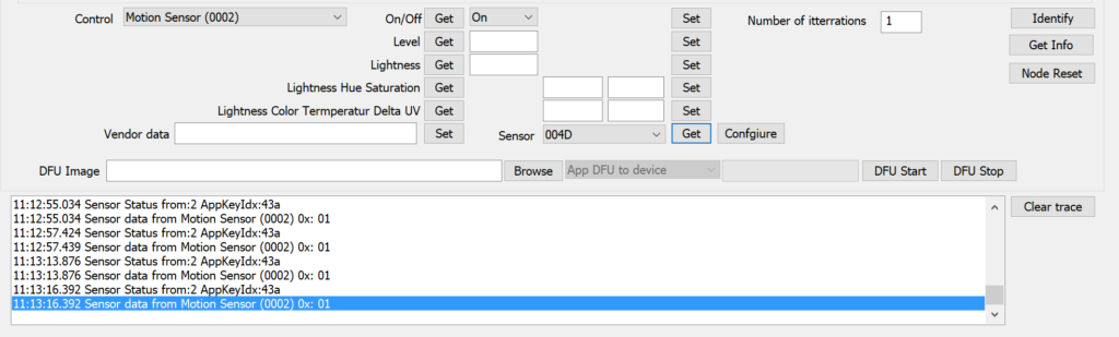
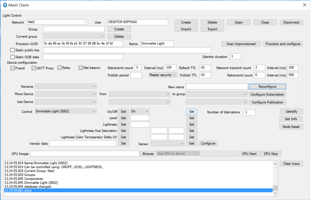
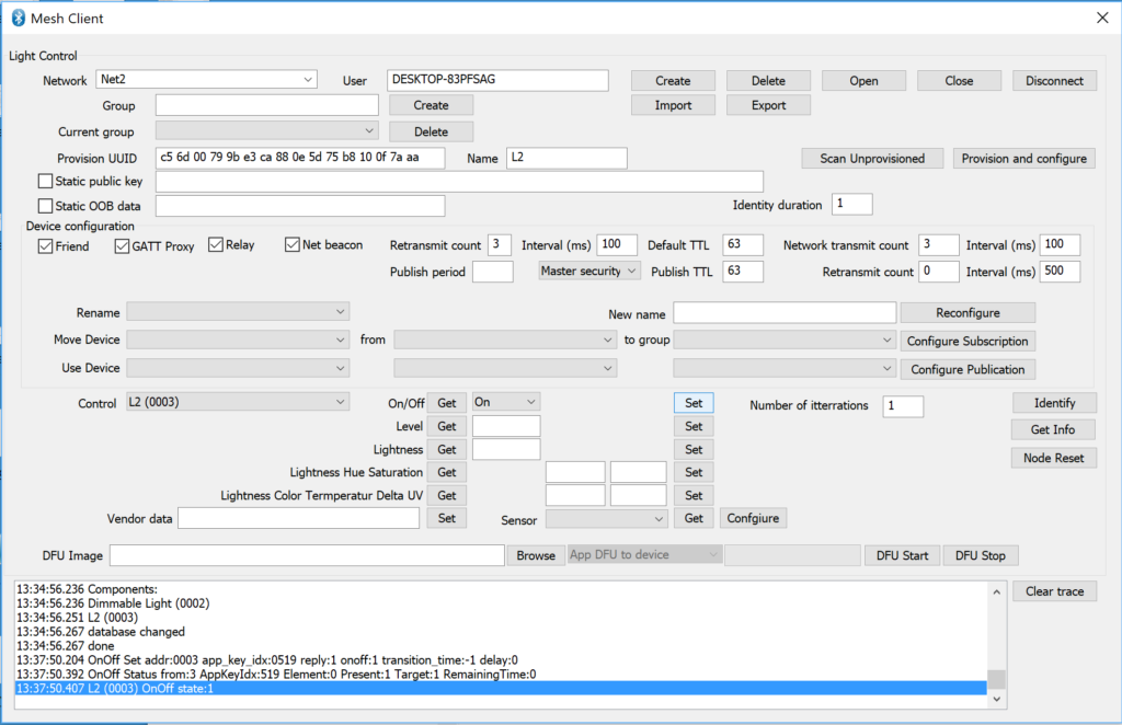
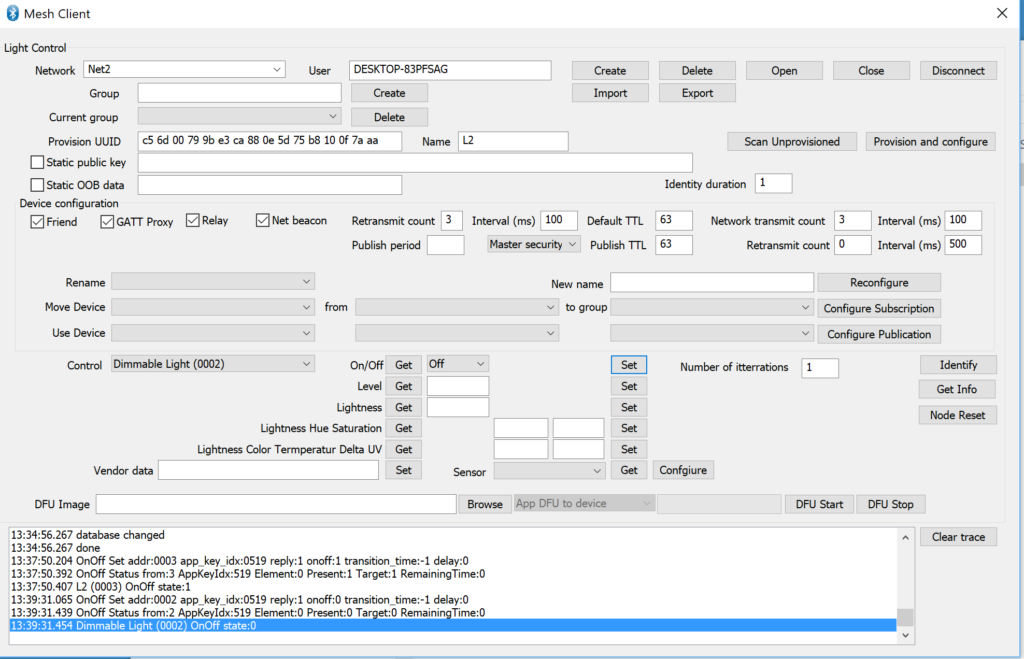
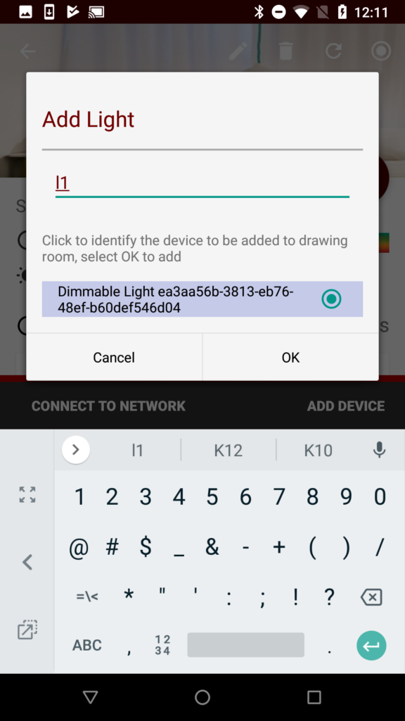
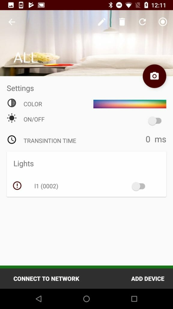
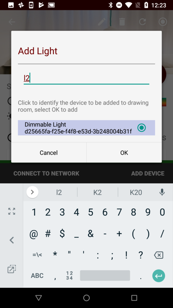
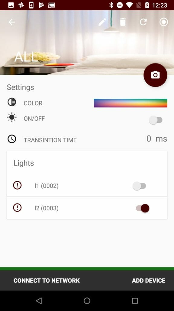
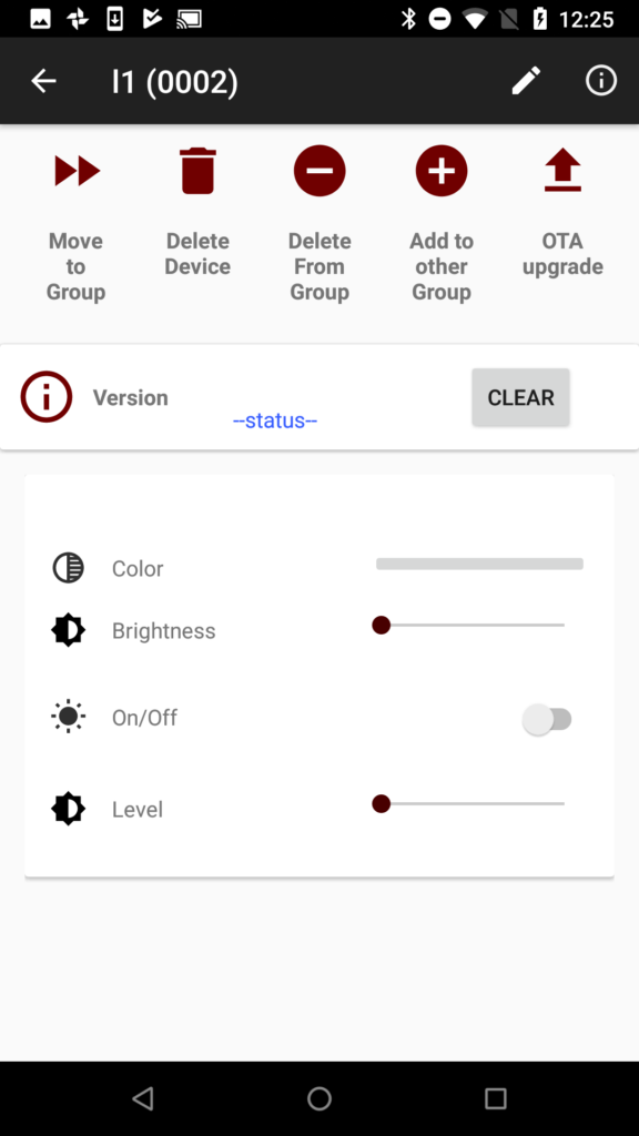
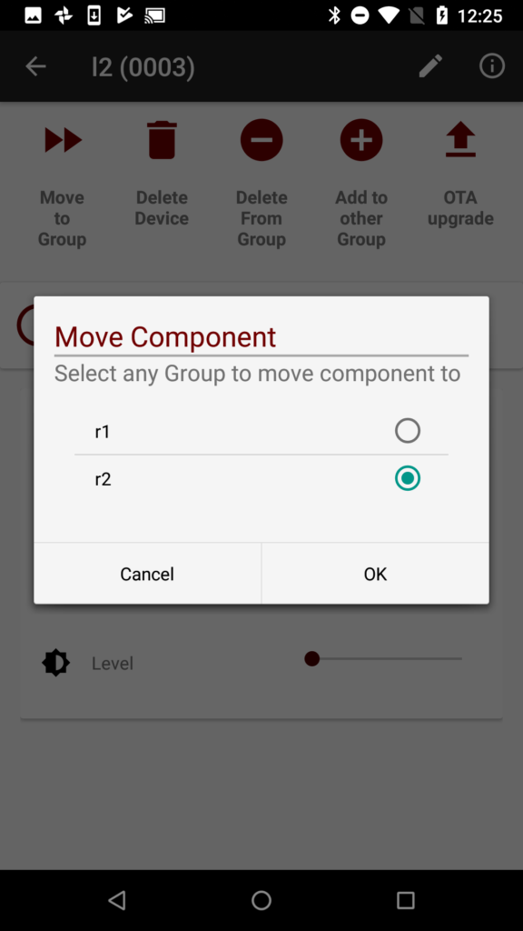
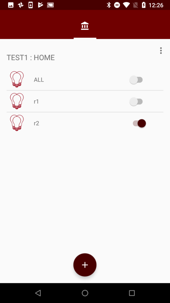
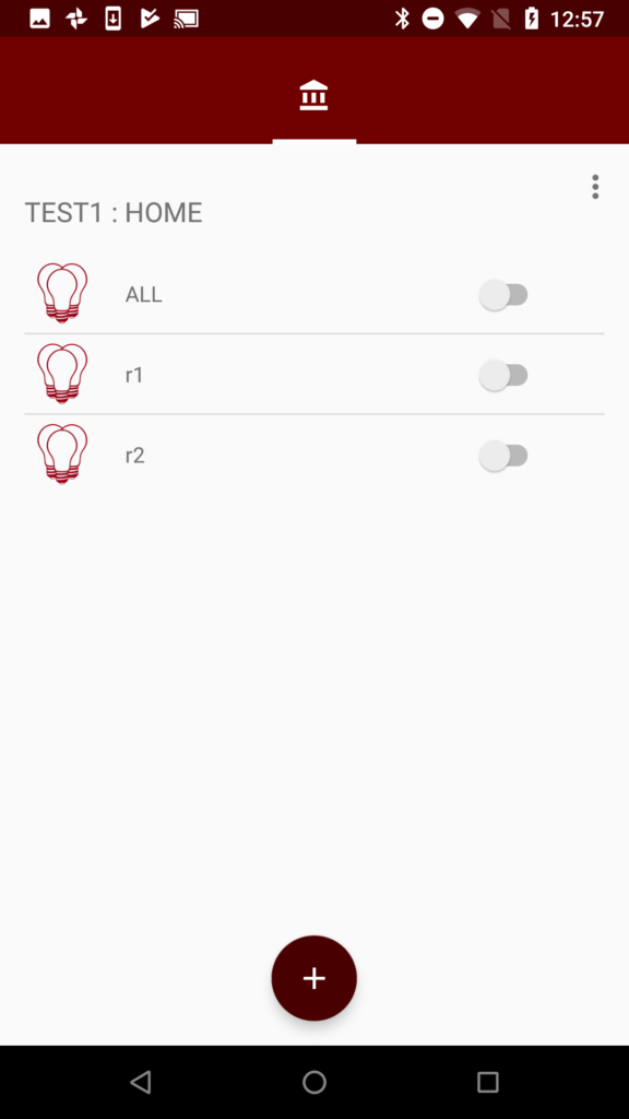
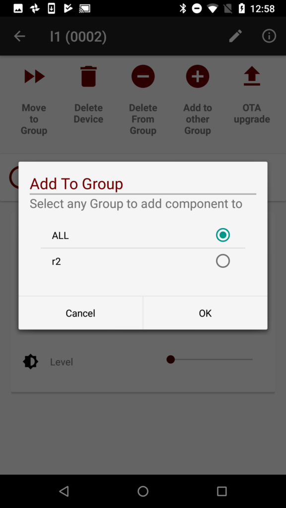
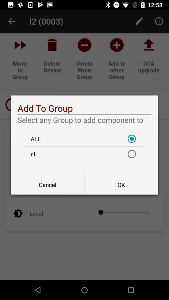
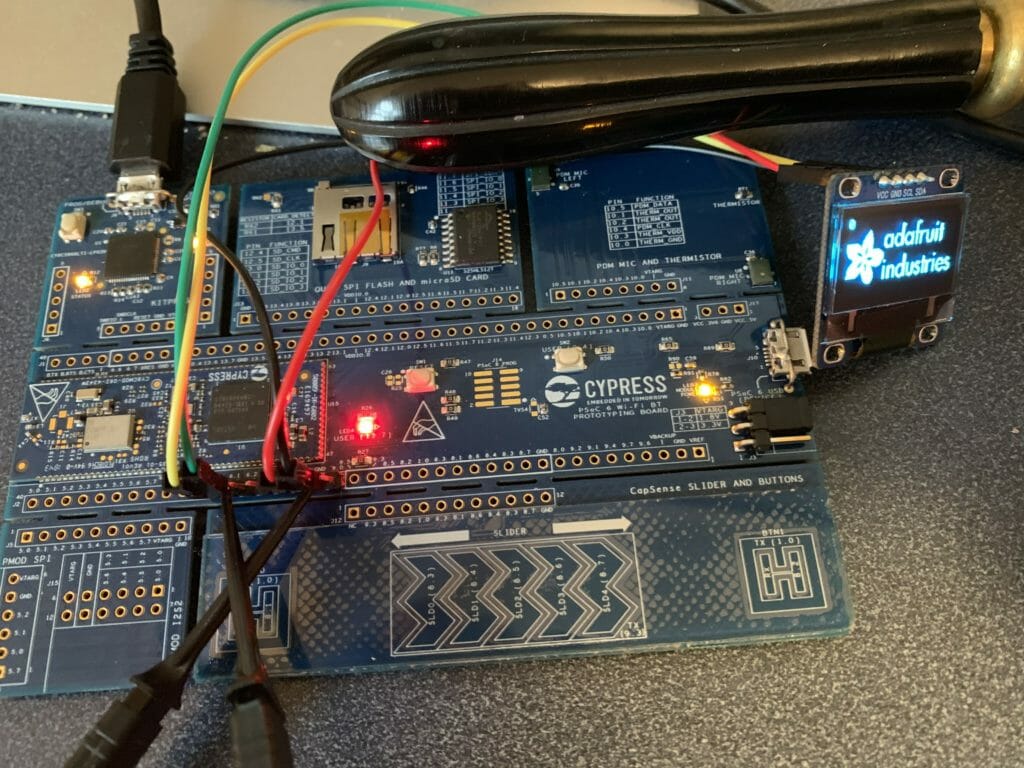
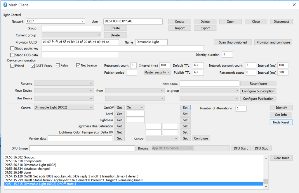
Now I can “Control” the two LEDs. Notice that the address of the first one is 0002 and the second is 0003.
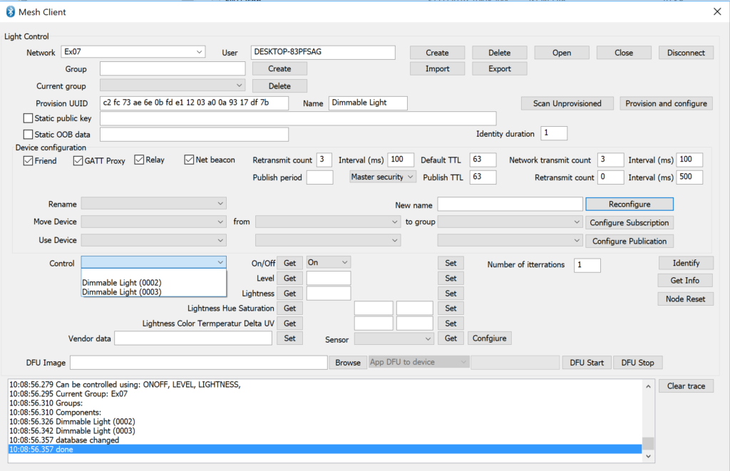
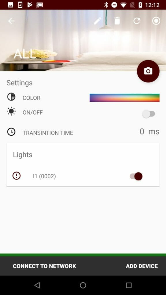
When I do “Set” I can turn on the Green LED.