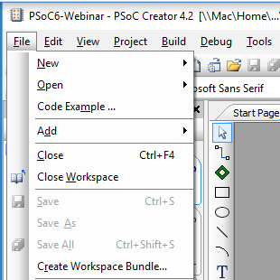
Designing low-power, cloud-connected IoT devices with PSoC® 6 MCU’s and WICED® Wi-Fi/Bluetooth
Summary
In this lesson I’ll finish the video game thread by adding the graphics etc. to play the game. In addition I’ll fix up the CapSense thread so that it is connected to the game via an RTOS queue.
There are three main things going on in this game.
- A state machine for the game screen (Splash, Start, Running, Over)
- A 20ms timer that updates the screen while the game is running (moves the Paddle and the Ball)
- A GUI queue where the rest of the system – CapSense, Bluetooth and WiFi – can send Button and Paddle messages.
To implement this project I will:
- Setup the project and makefile by copying L3CapSenseTft
- Update gamethread.h to define the GUI queue messages
- Fix main.c to create the queue
- Create SystemGlobal.h to give the rest of the files access to the gui queue
- Updating the CapSenseThread to send GUI messages
- Update the includes in GameThread.c
- Add some #define macros to define game parameters
- Add a State Machine for the game & define some paddle movement methods
- Make forward declarations for the thread functions
- Create some variables to maintain game state
- Add display functions for the score and the speed
- Add functions to start and end the game
- Add helper functions to calculate the top and bottom of the paddle
- Add a function to update and draw the paddle
- Add a function to update and draw the ball
- Add a function for the game timer to call
- Update the main game thread
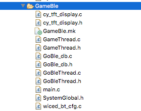
Setup the project and makefile by copying L3CapSenseTft
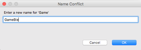
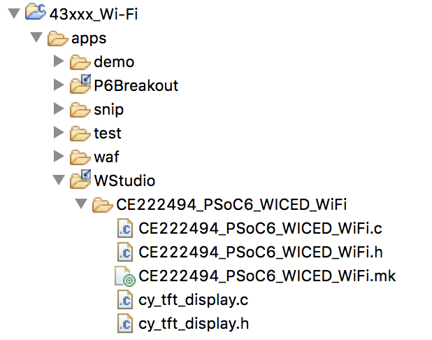
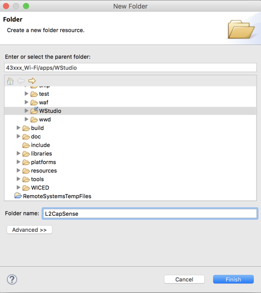
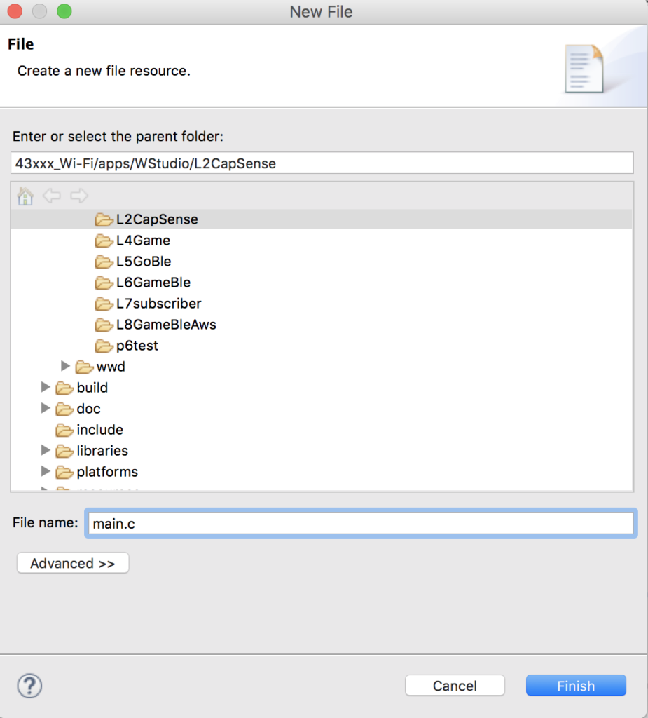
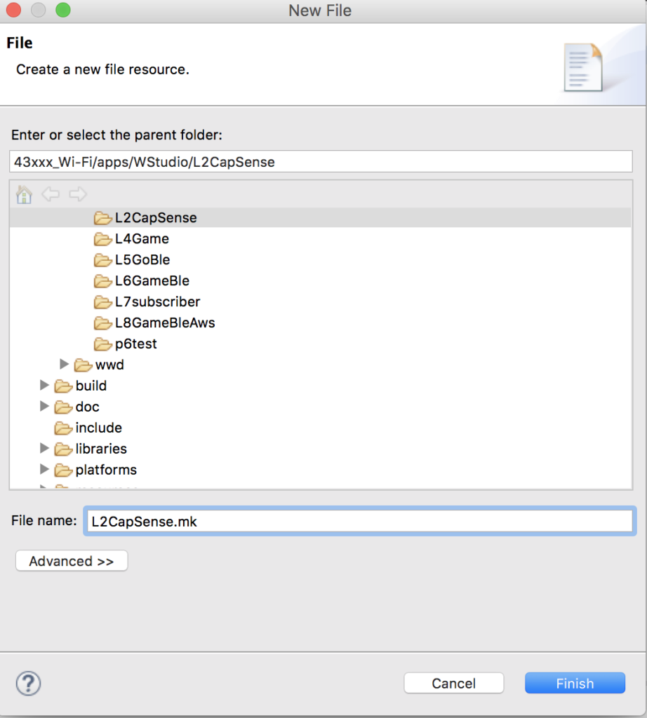
Use copy/paste to copy the L3CapSenseTft project to a new folder name L4Game. Change the name of the makefile to be L4Game.mk.
Edit the makefile and change the name of the application.
NAME := App_WStudio_L4Game
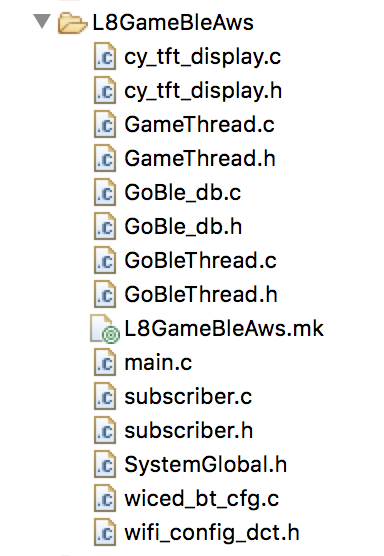
$(NAME)_SOURCES := main.c \
CapSenseThread.c \
GameThread.c \
cy_tft_display.c
$(NAME)_COMPONENTS := graphics/ugui
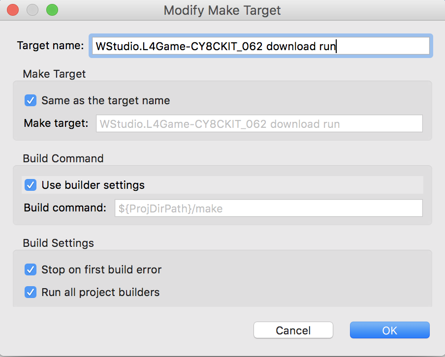
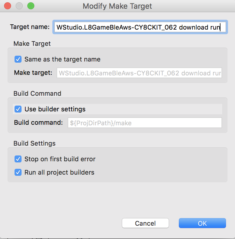
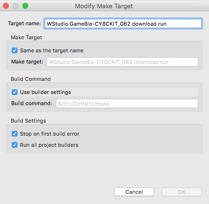
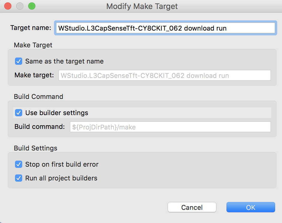
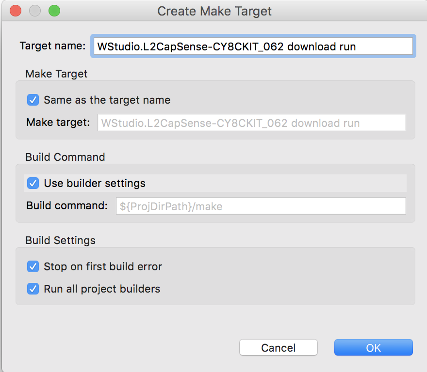
Create a make target for this project
Update GameThread.h to Define the GUI Messages
All of the threads in the system (CapSense, Bluetooth, and WiFi) will control the paddle and the button by sending messages to an RTOS queue. In gameThread.h we will add a definition of that message. The message is just a structure with two values – which GUI element and what value to send.
#pragma once
#include "wiced.h"
typedef enum {
MSG_POSITION,
MSG_BUTTON0,
MSG_BUTTON1,
} game_evt_t;
typedef struct {
game_evt_t evt;
uint32_t val;
} game_msg_t;
void gameThread(wiced_thread_arg_t arg);
Fix main.c to Create the Queue
I typically believe that the RTOS primitives should be owned by the main.c. To do this edit main.c and fix the includes.
#include "GameThread.h"
#include "wiced.h"
#include "CapSenseThread.h"
#include "SystemGlobal.h"
Then define the queue variable “paddleQueue” which I should have names “guiQueue” but it is way to late to fix it now — oh well.
/******************************************************
* Variable Definitions
******************************************************/
wiced_thread_t blinkThreadHandle;
wiced_thread_t capSenseThreadHandle;
wiced_thread_t gameThreadHandle;
wiced_queue_t paddleQueue;
Create the queue
void application_start( )
{
wiced_init( );
wiced_rtos_init_queue(&paddleQueue,"paddleQueue",sizeof(game_msg_t),10);
wiced_rtos_create_thread(&blinkThreadHandle,7,"Blink Thread",pdlBlinkThread,500,0);
wiced_rtos_create_thread(&capSenseThreadHandle,7,"CapSense Thread",capSenseThread,1024,0);
wiced_rtos_create_thread(&gameThreadHandle,7,"game Thread",gameThread,4096,0);
}
Create SystemGlobal.h
Each of the threads in the system need to have access to the paddleQueue. In order to do that create a file called SystemGlobal.h and extern the variable to give them that access.
#pragma once
extern wiced_queue_t paddleQueue;
Updating the CapSenseThread to send GUI messages
Remember that when we setup the CapSenseThread originally, it just printed out the values. Let’s fix it so send messages. So, edit CapSenseThread.c.
- Add a message variable (line 8)
- Fix the button0 and button 1 to make and send RTOS messages (lines 20/21 and 26/27)
- Fix the slider to send the position (lines 33-35)
#include "wiced.h"
#include "GameThread.h"
#include "SystemGlobal.h"
void capSenseThread(wiced_thread_arg_t arg)
{
game_msg_t msg;
CapSense_Start();
CapSense_ScanAllWidgets();
while(1)
{
if(!CapSense_IsBusy())
{
CapSense_ProcessAllWidgets();
if(CapSense_IsWidgetActive(CapSense_BUTTON0_WDGT_ID))
{
msg.evt = MSG_BUTTON0;
wiced_rtos_push_to_queue(&paddleQueue,&msg,0);
}
if(CapSense_IsWidgetActive(CapSense_BUTTON1_WDGT_ID))
{
msg.evt = MSG_BUTTON1;
wiced_rtos_push_to_queue(&paddleQueue,&msg,0);
}
uint32_t val = CapSense_GetCentroidPos(CapSense_LINEARSLIDER0_WDGT_ID);
if(val < 0xFFFF)
{
msg.evt = MSG_POSITION;
msg.val = val;
wiced_rtos_push_to_queue(&paddleQueue,&msg,0);
}
CapSense_ScanAllWidgets();
}
wiced_rtos_delay_milliseconds(25); // Poll every 25ms (actual scan time ~8ms)
}
}
Update the includes in GameThread.c
Now let’s fix GameThread.c. Start by editing the includes to add a new file called “SystemGlobal.h” which contains the global variable for the GUI queue.
#include "GameThread.h"
#include "cy_tft_display.h"
#include "SystemGlobal.h"
#include "ugui.h"
Add some #define macros in GameThread.c
There are a number of constants which I use in the game. In this section I use #define macros to define them.
#define UPDATE_SCREEN_TIME (20) // Update the screen every 20ms
#define SPEED (2)
#define SCREEN_X (320)
#define SCREEN_Y (240)
#define TOP_FIELD (21)
#define PD_WIDTH (10)
#define PD_LEN (70)
#define DOTS (3)
#define PADDLE0_COLOR (C_BLUE)
#define BALL_COLOR (C_GREEN)
#define BALL_SIZE (10)
Add a State Machine for the Game & Define Paddle Movement
Open up GameThread.c – all of the game control functions will go there.
There will be four screens in the game. A splash screen to display Cypress and Mouser, a Ready Player 1 Screen, the actual game screen and a game over screen.
In addition the paddle can move a little bit at a time (increment) or jump directly to the position (absolute)
// States of the game
typedef enum {
    GS_SPLASH,
    GS_START,
    GS_RUNNING,
    GS_OVER
} game_state_t;

// Methods to move the paddle
typedef enum {
    PADDLE_INCREMENT,
    PADDLE_ABSOLUTE
} paddle_update_t;
Fix the gameState statemachine
In the splash screen I need to set the state machine to GS_SPLASH
static void displaySplashScreen()
{
    gameState = GS_SPLASH;
    UG_FontSelect( &FONT_22X36 );
    UG_PutStringCenter(SCREEN_X/2,SCREEN_Y/5,22,36,"Cypress");
    UG_PutStringCenter(SCREEN_X/2,SCREEN_Y/5*2,22,36,"Mouser");
    UG_PutStringCenter(SCREEN_X/2,SCREEN_Y/5*3,22,36,"PSoC 6");
    UG_PutStringCenter(SCREEN_X/2,SCREEN_Y/5*4,22,36,"WICED 4343");

    wiced_rtos_delay_milliseconds(2000);
}
In the start screen I need to set the state machine to GS_START
// Display the Start Screen
static void  displayStartScreen()
{
    gameState = GS_START;
    UG_FillScreen( C_BLACK );
    UG_FontSelect( &FONT_22X36 );
    UG_PutStringCenter(SCREEN_X/2,SCREEN_Y/2 -2 - 18 ,22,36,"Ready");
    UG_PutStringCenter(SCREEN_X/2,SCREEN_Y/2 + 2 + 18 ,22,36,"Player 1");
    displayStartButton();
}
Make Forward Declarations for Functions
You should define the functions in advance of using them
/******************************************************
 *               Static Function Declarations
 ******************************************************/
static void UG_PutStringCenter(uint32_t x, uint32_t y, uint32_t fontx, uint32_t fonty,char *string);
static void displaySplashScreen();
static void displayStartButton();
static void  displayStartScreen();
static void displayScore();
static void displaySpeed();
static void endGame();
static inline uint32_t calcPaddleTop();
static inline uint32_t calcPaddleBottom();
static void updatePaddle(paddle_update_t type);
static void updateBall();
static void updateScreen(void *arg);
Create some variables to maintain game state
The updateScreenTimer is used while the game is running to call the updateScreen every 20ms. The rest of the variables are self explanatory.
/******************************************************
 *               Variable Definitions
 ******************************************************/
static UG_GUI   gui;
static wiced_timer_t updateScreenTimer;

static uint32_t gameScore;
static game_state_t gameState;

// position of the paddle
static uint32_t paddle0_desire_pos=0;
static uint32_t paddle0_cur_pos=0;

// Position, direction and speed of the ball
static uint32_t ballx,bally;
static int32_t ballXdir, ballYdir;
static uint32_t ballSpeed;
Add Display Functions for the Score & Speed
These two functions print the speed and score at the top of the screen.
// This function displays the score
static void displayScore()
{
    char buff[10];
    sprintf(buff,"%2X",(unsigned int)gameScore);
    UG_FontSelect(&FONT_12X20);
    UG_PutString( 75, 0, buff);
}

// This function displays the speed
static void displaySpeed()
{
    char buff[10];
    sprintf(buff,"%2X",(unsigned int)ballSpeed-1);
    UG_FontSelect(&FONT_12X20);
    UG_PutString( 275, 0, buff);
}
Add Function to Start the Game
When the game needs to start you:
- Reset the score
- Set the paddle position
- Move the ball to the middle of the paddle
- Set the ball to move to the right and down
- Clear the screen, display score and speed
- Start the game running
// This function initializes everything and starts a new game
static void startGame()
{
    gameScore = 0;

    paddle0_desire_pos = 50; // start the game with the paddle moving
    paddle0_cur_pos = 0;

    ballx = PD_WIDTH ;                   // start the ball on the paddle on the right of the screen
    bally  = calcPaddleTop() + PD_LEN/2; // start the ball in the middle of the paddle

    ballSpeed = SPEED;

    ballXdir = ballSpeed;
    ballYdir = ballSpeed;

    UG_FillScreen( C_BLACK );  // clear screen
    UG_FontSelect(&FONT_12X20);
    UG_PutString( 0, 0,  "Score:");
    displayScore();
    UG_PutString(200,0,"Speed:");
    displaySpeed();
    UG_DrawLine(0,20,SCREEN_X,20,C_RED); // red line under text to represent top of play screen

    gameState = GS_RUNNING;
    wiced_rtos_start_timer(&updateScreenTimer); // Timer to update screen
}
Add Function to End the Game
When the game is over you should:
- Move the game state to over
- Stop the timer
- Display game over
- Display press button 0 to start
// Stop the game
static void endGame()
{
    gameState = GS_OVER;
    wiced_rtos_stop_timer(&updateScreenTimer);
    UG_FontSelect( &FONT_22X36 );
    UG_PutStringCenter(SCREEN_X/2,SCREEN_Y/2,22,36,"Game Over");
    displayStartButton();
}
Add Helper Functions to Calculate Paddle Top & Bottom
There are two places where you need to know the position of the Paddle. Specifically:
- To draw the paddle
- To figure out if the ball hit the paddle or not.
These two functions calculate the pixel position of the top and bottom of the paddle based on it current position
// Figure out the y position of the top of the paddle
static inline uint32_t calcPaddleTop()
{
    return (paddle0_cur_pos)*DOTS+TOP_FIELD;
}

// Figure out the y position of the bottom of the paddle
static inline uint32_t calcPaddleBottom()
{
    return (paddle0_cur_pos)*DOTS+PD_LEN+TOP_FIELD;
}
Add a Function to Update & Draw the Paddle
While the game is running you need the paddle to move. There are two methods:
- Absolute just moves the current position immediately to the desired position.
- Incremental, which moves the paddle a little bit towards the desired position.
// Move the paddle either to : PADDLE_INCREMENT the next location or PADDLE_ABSOLUTE - final location
static void updatePaddle(paddle_update_t type)
{
    // If the paddle is where it is supposed to be then just return
    if(paddle0_cur_pos == paddle0_desire_pos)
        return;

    // erase the current paddle
    UG_FillFrame(0,calcPaddleTop(),PD_WIDTH,calcPaddleBottom(),C_BLACK);

    switch (type)
    {

    case PADDLE_INCREMENT:

        if(paddle0_cur_pos < paddle0_desire_pos)
            paddle0_cur_pos += SPEED;
        else
            paddle0_cur_pos -= SPEED;

        // If the paddle is within one move of the final spot, put it there
        if(abs((int)paddle0_cur_pos-(int)paddle0_desire_pos) < SPEED)
            paddle0_cur_pos = paddle0_desire_pos;
        break;

    case PADDLE_ABSOLUTE:
        paddle0_cur_pos = paddle0_desire_pos;
        break;
    }
    // draw the paddle
    UG_FillFrame(0,calcPaddleTop(),PD_WIDTH,calcPaddleBottom(),PADDLE0_COLOR);
}
Add a function to update and draw the ball
You need a function to:
- Move the ball
- Figure out if it hit the right/left/top/bottom of the screen and do the right thing.
When the ball hits one of those surfaces it needs to change direction to either plus or minus.
Every time it hits the paddle the score should increase and possibly speed up.
If it misses the paddle the game is over.
// Move the ball to the next location
static void updateBall()
{
    static const uint32_t BallFudgeFactor=3;

    UG_DrawCircle(ballx,bally,BALL_SIZE,C_BLACK);

    ballx += ballXdir;
    bally += ballYdir;

    // Check to see if the ball hit the far right side
    if(ballx > SCREEN_X - BALL_SIZE)
    {

        ballx = SCREEN_X - BALL_SIZE;
        ballXdir = -ballSpeed;
    }

    // check to see if the ball hit the far left side... or the paddle
    if(ballx < (BALL_SIZE + PD_WIDTH + BallFudgeFactor))
    {
        // See if the ball missed the paddle
        if(bally + BALL_SIZE < calcPaddleTop() || bally - BALL_SIZE > calcPaddleBottom())
        {
            endGame();
            //WPRINT_APP_INFO(("Missed Paddle\r\n"));
        }

        gameScore = gameScore + 1;
        displayScore();
        if(gameScore % 3 == 0) // Speed up every three hits
        {
            ballSpeed +=1;
            displaySpeed();
        }

        ballx = BALL_SIZE + PD_WIDTH + BallFudgeFactor;
        ballXdir = +ballSpeed;
    }
    // Check to see if the ball hit the top or bottom
    if(bally > SCREEN_Y - BALL_SIZE) // bottom
    {
        bally = SCREEN_Y - BALL_SIZE;
        ballYdir = -ballSpeed;
    }

    if(bally < TOP_FIELD+BALL_SIZE) // top
    {
        bally = BALL_SIZE+TOP_FIELD;
        ballYdir = +ballSpeed;
    }
    UG_DrawCircle(ballx,bally,BALL_SIZE,BALL_COLOR);
}
Create a Function for the Game Timer
An RTOS timer runs every 20ms. That timer needs a function to move the paddle and move the ball.
// This function is called every UPADTE_SCREEN_TIME milliseconds by the updateScreenTimer
static void updateScreen(void *arg)
{
    updatePaddle(PADDLE_INCREMENT);
    updateBall();
}
Update the Main Game Thread
The main game thread needs to get messages out of the queue and then do the right thing based on the game state.
// Main game thread
void gameThread(wiced_thread_arg_t arg)
{
    game_msg_t msg;

    Cy_TFT_Init();                                             // Init the TFT
    UG_Init( &gui, Cy_TFT_displayDriver, SCREEN_X, SCREEN_Y ); // Connect the driver

    UG_FillScreen( C_BLACK );   // Clear the screen
    UG_SetBackcolor( C_BLACK );
    UG_SetForecolor( C_WHITE );

    wiced_rtos_init_timer(&updateScreenTimer,UPDATE_SCREEN_TIME,updateScreen,0);
    displaySplashScreen();
    displayStartScreen();

    while(1)
    {
        wiced_rtos_pop_from_queue(&paddleQueue,&msg,WICED_WAIT_FOREVER);
        switch(msg.evt)
        {
        case MSG_POSITION:
            if(gameState == GS_RUNNING)
                paddle0_desire_pos = msg.val/2;
            if(gameState == GS_OVER)
            {
                paddle0_desire_pos = msg.val/2;
                updatePaddle(PADDLE_ABSOLUTE);
            }
            break;

        case MSG_BUTTON0:
            if(gameState == GS_OVER || gameState == GS_START)
                startGame();
            break;
        case MSG_BUTTON1:
            break;
        }
    }
}
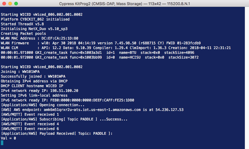
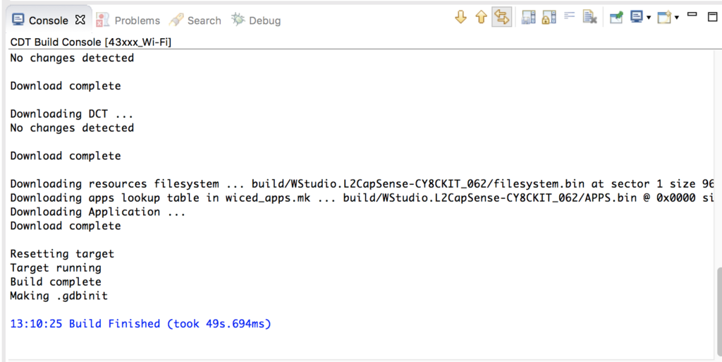
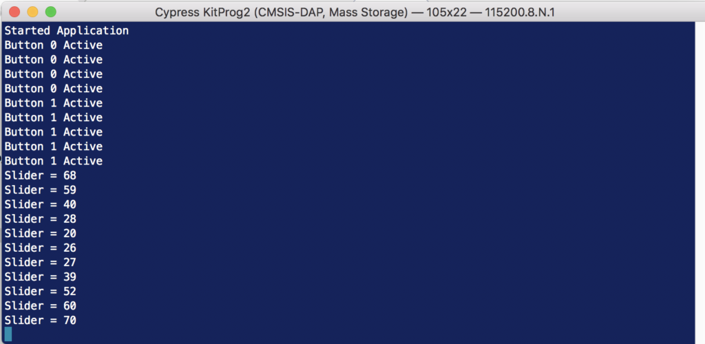
Program and Test
Now that it is all done… program and test it.
GameThread.c
Here is the whole thread is here so you can copy/paste it into your file.
#include "GameThread.h"
#include "cy_tft_display.h"
#include "SystemGlobal.h"
#include "ugui.h"

/******************************************************
 *                      Macros
 ******************************************************/
#define UPDATE_SCREEN_TIME (20) // Update the screen every 20ms
#define SPEED (2)
#define SCREEN_X (320)
#define SCREEN_Y (240)
#define TOP_FIELD (21)
#define PD_WIDTH (10)
#define PD_LEN (70)
#define DOTS (3)
#define PADDLE0_COLOR (C_BLUE)
#define BALL_COLOR (C_GREEN)
#define BALL_SIZE (10)

/******************************************************
 *                    Constants
 ******************************************************/

/******************************************************
 *                   Enumerations
 ******************************************************/

/******************************************************
 *                 Type Definitions
 ******************************************************/
// States of the game
typedef enum {
    GS_SPLASH,
    GS_START,
    GS_RUNNING,
    GS_OVER
} game_state_t;

// Methods to move the paddle
typedef enum {
    PADDLE_INCREMENT,
    PADDLE_ABSOLUTE
} paddle_update_t;

/******************************************************
 *                    Structures
 ******************************************************/


/******************************************************
 *               Static Function Declarations
 ******************************************************/
static void UG_PutStringCenter(uint32_t x, uint32_t y, uint32_t fontx, uint32_t fonty,char *string);
static void displaySplashScreen();
static void displayStartButton();
static void  displayStartScreen();
static void displayScore();
static void displaySpeed();
static void endGame();
static inline uint32_t calcPaddleTop();
static inline uint32_t calcPaddleBottom();
static void updatePaddle(paddle_update_t type);
static void updateBall();
static void updateScreen(void *arg);

/******************************************************
 *               Variable Definitions
 ******************************************************/
static UG_GUI   gui;
static wiced_timer_t updateScreenTimer;

static uint32_t gameScore;
static game_state_t gameState;

// position of the paddle
static uint32_t paddle0_desire_pos=0;
static uint32_t paddle0_cur_pos=0;

// Position, direction and speed of the ball
static uint32_t ballx,bally;
static int32_t ballXdir, ballYdir;
static uint32_t ballSpeed;


/******************************************************
 *               Functions
 ******************************************************/

// ARH Function to put text in the center of a point (UG_PutString does upper left)
static void UG_PutStringCenter(uint32_t x, uint32_t y, uint32_t fontx, uint32_t fonty,char *string)
{
    y = y - fonty/2;
    x = x - (strlen(string)/2)*fontx;
    if(strlen(string)%2)
        x = x - fontx/2;
    UG_PutString(x,y,string);
}


// Display the splash screen
static void displaySplashScreen()
{
    gameState = GS_SPLASH;
    UG_FontSelect( &FONT_22X36 );
    UG_PutStringCenter(SCREEN_X/2,SCREEN_Y/5,22,36,"Cypress");
    UG_PutStringCenter(SCREEN_X/2,SCREEN_Y/5*2,22,36,"Mouser");
    UG_PutStringCenter(SCREEN_X/2,SCREEN_Y/5*3,22,36,"PSoC 6");
    UG_PutStringCenter(SCREEN_X/2,SCREEN_Y/5*4,22,36,"WICED 4343");

    wiced_rtos_delay_milliseconds(2000);
}

// This function displays the start button message
static void displayStartButton()
{
    UG_FontSelect(&FONT_12X20);
    UG_PutStringCenter(SCREEN_X/2 , SCREEN_Y - 30 ,12,22,  "Press B0 To Start");
}

// Display the Start Screen
static void  displayStartScreen()
{
    gameState = GS_START;
    UG_FillScreen( C_BLACK );
    UG_FontSelect( &FONT_22X36 );
    UG_PutStringCenter(SCREEN_X/2,SCREEN_Y/2 -2 - 18 ,22,36,"Ready");
    UG_PutStringCenter(SCREEN_X/2,SCREEN_Y/2 + 2 + 18 ,22,36,"Player 1");
    displayStartButton();
}


// This function displays the score
static void displayScore()
{
    char buff[10];
    sprintf(buff,"%2X",(unsigned int)gameScore);
    UG_FontSelect(&FONT_12X20);
    UG_PutString( 75, 0, buff);
}

// This function displays the speed
static void displaySpeed()
{
    char buff[10];
    sprintf(buff,"%2X",(unsigned int)ballSpeed-1);
    UG_FontSelect(&FONT_12X20);
    UG_PutString( 275, 0, buff);
}


// This function initializes everything and starts a new game
static void startGame()
{
    gameScore = 0;

    paddle0_desire_pos = 50; // start the game with the paddle moving
    paddle0_cur_pos = 0;

    ballx = PD_WIDTH ;                   // start the ball on the paddle on the right of the screen
    bally  = calcPaddleTop() + PD_LEN/2; // start the ball in the middle of the paddle

    ballSpeed = SPEED;

    ballXdir = ballSpeed;
    ballYdir = ballSpeed;

    UG_FillScreen( C_BLACK );  // clear screen
    UG_FontSelect(&FONT_12X20);
    UG_PutString( 0, 0,  "Score:");
    displayScore();
    UG_PutString(200,0,"Speed:");
    displaySpeed();
    UG_DrawLine(0,20,SCREEN_X,20,C_RED); // red line under text to represent top of play screen

    gameState = GS_RUNNING;
    wiced_rtos_start_timer(&updateScreenTimer); // Timer to update screen
}

// Stop the game
static void endGame()
{
    gameState = GS_OVER;
    wiced_rtos_stop_timer(&updateScreenTimer);
    UG_FontSelect( &FONT_22X36 );
    UG_PutStringCenter(SCREEN_X/2,SCREEN_Y/2,22,36,"Game Over");
    displayStartButton();
}


// Figure out the y position of the top of the paddle
static inline uint32_t calcPaddleTop()
{
    return (paddle0_cur_pos)*DOTS+TOP_FIELD;
}

// Figure out the y position of the bottom of the paddle
static inline uint32_t calcPaddleBottom()
{
    return (paddle0_cur_pos)*DOTS+PD_LEN+TOP_FIELD;
}

// Move the paddle either to : PADDLE_INCREMENT the next location or PADDLE_ABSOLUTE - final location
static void updatePaddle(paddle_update_t type)
{
    // If the paddle is where it is supposed to be then just return
    if(paddle0_cur_pos == paddle0_desire_pos)
        return;

    // erase the current paddle
    UG_FillFrame(0,calcPaddleTop(),PD_WIDTH,calcPaddleBottom(),C_BLACK);

    switch (type)
    {

    case PADDLE_INCREMENT:

        if(paddle0_cur_pos < paddle0_desire_pos)
            paddle0_cur_pos += SPEED;
        else
            paddle0_cur_pos -= SPEED;

        // If the paddle is within one move of the final spot, put it there
        if(abs((int)paddle0_cur_pos-(int)paddle0_desire_pos) < SPEED)
            paddle0_cur_pos = paddle0_desire_pos;
        break;

    case PADDLE_ABSOLUTE:
        paddle0_cur_pos = paddle0_desire_pos;
        break;
    }
    // draw the paddle
    UG_FillFrame(0,calcPaddleTop(),PD_WIDTH,calcPaddleBottom(),PADDLE0_COLOR);
}

// Move the ball to the next location
static void updateBall()
{
    static const uint32_t BallFudgeFactor=3;

    UG_DrawCircle(ballx,bally,BALL_SIZE,C_BLACK);

    ballx += ballXdir;
    bally += ballYdir;

    // Check to see if the ball hit the far right side
    if(ballx > SCREEN_X - BALL_SIZE)
    {

        ballx = SCREEN_X - BALL_SIZE;
        ballXdir = -ballSpeed;
    }

    // check to see if the ball hit the far left side... or the paddle
    if(ballx < (BALL_SIZE + PD_WIDTH + BallFudgeFactor))
    {
        // See if the ball missed the paddle
        if(bally + BALL_SIZE < calcPaddleTop() || bally - BALL_SIZE > calcPaddleBottom())
        {
            endGame();
            //WPRINT_APP_INFO(("Missed Paddle\r\n"));
        }

        gameScore = gameScore + 1;
        displayScore();
        if(gameScore % 3 == 0) // Speed up every three hits
        {
            ballSpeed +=1;
            displaySpeed();
        }

        ballx = BALL_SIZE + PD_WIDTH + BallFudgeFactor;
        ballXdir = +ballSpeed;
    }
    // Check to see if the ball hit the top or bottom
    if(bally > SCREEN_Y - BALL_SIZE) // bottom
    {
        bally = SCREEN_Y - BALL_SIZE;
        ballYdir = -ballSpeed;
    }

    if(bally < TOP_FIELD+BALL_SIZE) // top
    {
        bally = BALL_SIZE+TOP_FIELD;
        ballYdir = +ballSpeed;
    }
    UG_DrawCircle(ballx,bally,BALL_SIZE,BALL_COLOR);
}

// This function is called every UPADTE_SCREEN_TIME milliseconds by the updateScreenTimer
static void updateScreen(void *arg)
{
    updatePaddle(PADDLE_INCREMENT);
    updateBall();
}


// Main game thread
void gameThread(wiced_thread_arg_t arg)
{
    game_msg_t msg;

    Cy_TFT_Init();                                             // Init the TFT
    UG_Init( &gui, Cy_TFT_displayDriver, SCREEN_X, SCREEN_Y ); // Connect the driver

    UG_FillScreen( C_BLACK );   // Clear the screen
    UG_SetBackcolor( C_BLACK );
    UG_SetForecolor( C_WHITE );

    wiced_rtos_init_timer(&updateScreenTimer,UPDATE_SCREEN_TIME,updateScreen,0);
    displaySplashScreen();
    displayStartScreen();

    while(1)
    {
        wiced_rtos_pop_from_queue(&paddleQueue,&msg,WICED_WAIT_FOREVER);
        switch(msg.evt)
        {
        case MSG_POSITION:
            if(gameState == GS_RUNNING)
                paddle0_desire_pos = msg.val/2;
            if(gameState == GS_OVER)
            {
                paddle0_desire_pos = msg.val/2;
                updatePaddle(PADDLE_ABSOLUTE);
            }
            break;

        case MSG_BUTTON0:
            if(gameState == GS_OVER || gameState == GS_START)
                startGame();
            break;
        case MSG_BUTTON1:
            break;
        }
    }
}


