In the previous article I showed you how to build PSoC4 BLE Central firmware to talk to a BLE Peripheral. When I did that firmware I built it to program into a CY8CKIT-042-BLE kit. What I should have done was made the firmware work with the CySmart Dongle. An error that I will fix in this article.
In this article I give you an introduction to the CySmart dongle, then I will show you how to:
Update the firmware on the dongle (both KitProg and the PRoC)
Use the PC to debug a PSoC4 BLE Peripheral
Modify the PSoC4 BLE Central Project to work on the CySmart Dongle
CySmart Dongle
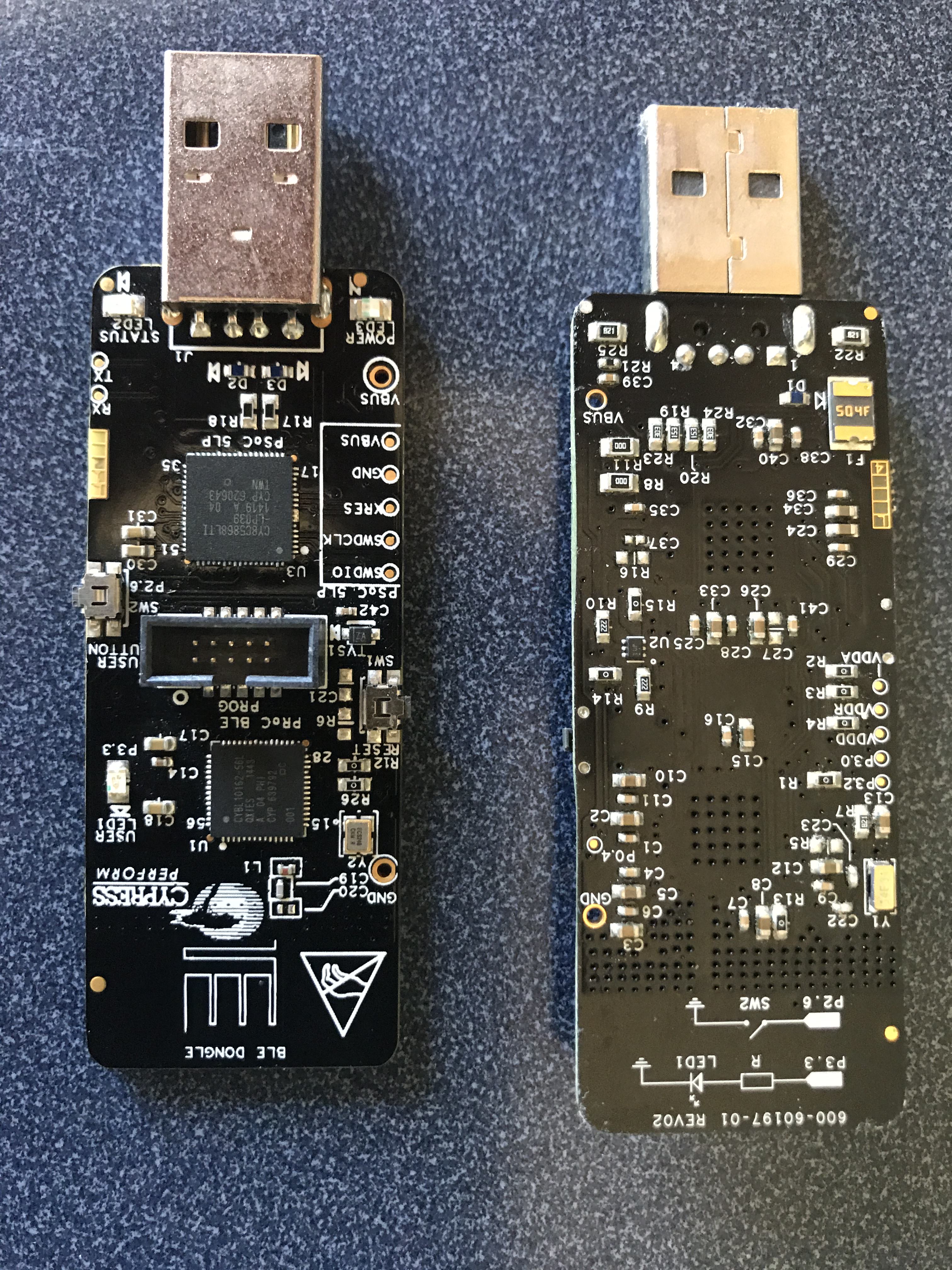
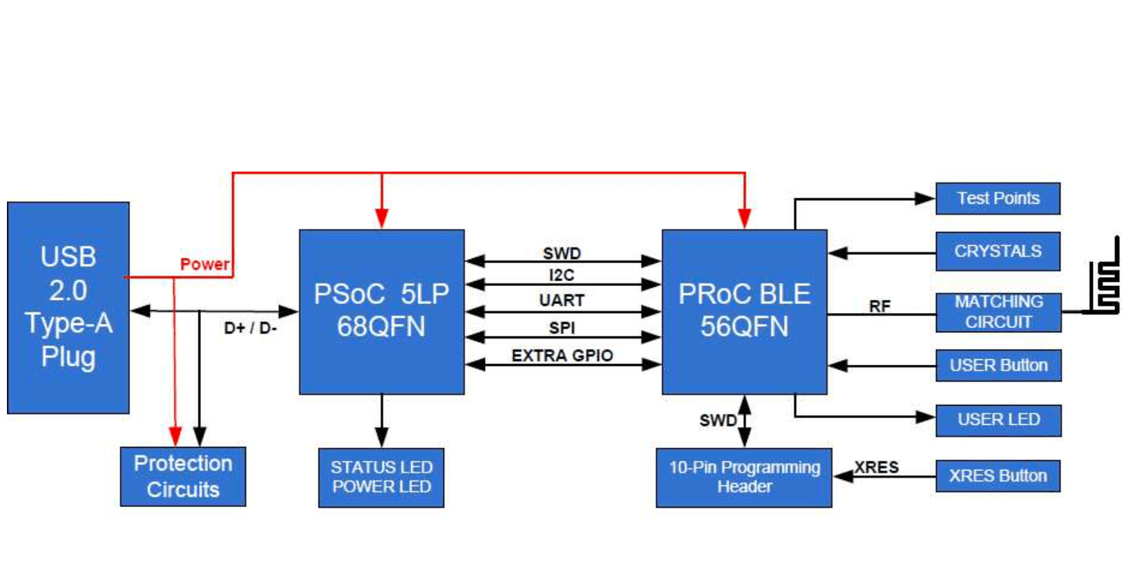
As you can see in the picture above, the CySmart dongle is a USB dongle with a PRoC BLE Radio on it. It uses a PSoC5 programmed with the KitProg firmware to bridge from the PRoC to the PC. In the diagram below you can see that it can bridge SWD, I2C, UART and SPI. In addition the dongle has 1 user button and 1 user LED. This is perfect for the PSoC4 BLE CapSense LED GAP Central Project that I built in the previous article.
You get the CySmart dongle as part of the CY8CKIT-042-BLE Kit. The dongle comes programmed with the CySmart Firmware which enables you to connect to the CySmart PC Program (more later in this article).
There are two version of the dongle
CY5670 with PRoC & 128K of Flash
CY5671 with PRoC & 256K of Flash
Update the CySmart Dongle
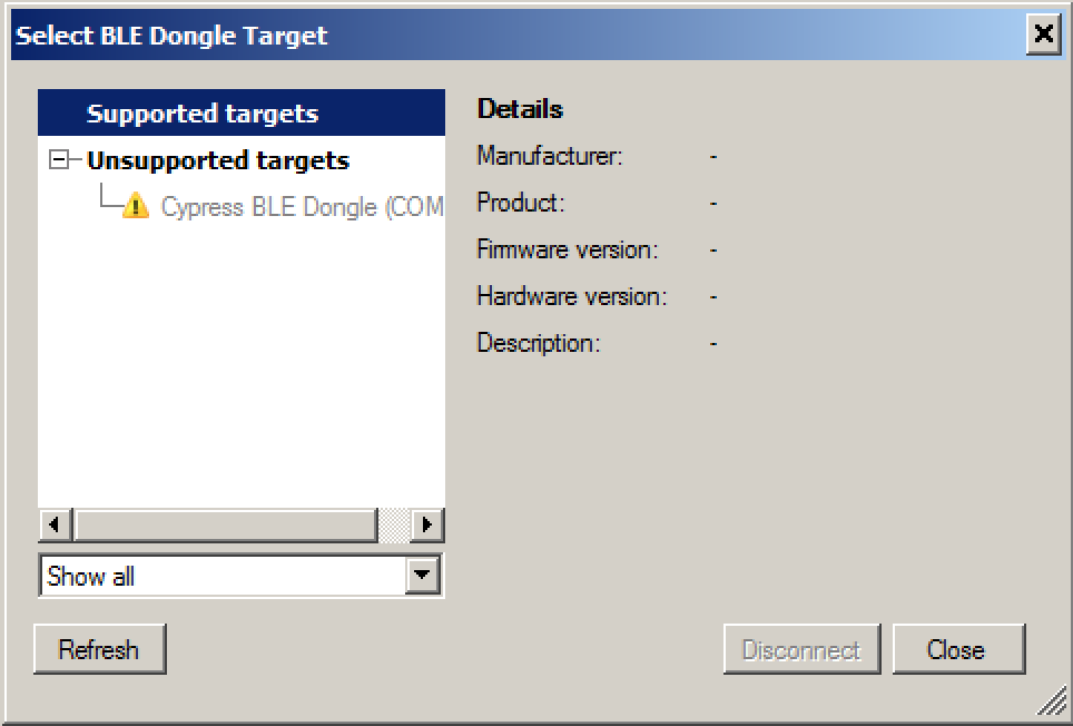
Literally (well almost) every time I plug in a CySmart dongle, I get this message telling me that it is an “Unsupported Target”. This means that the firmware is out of date and needs to be updated.
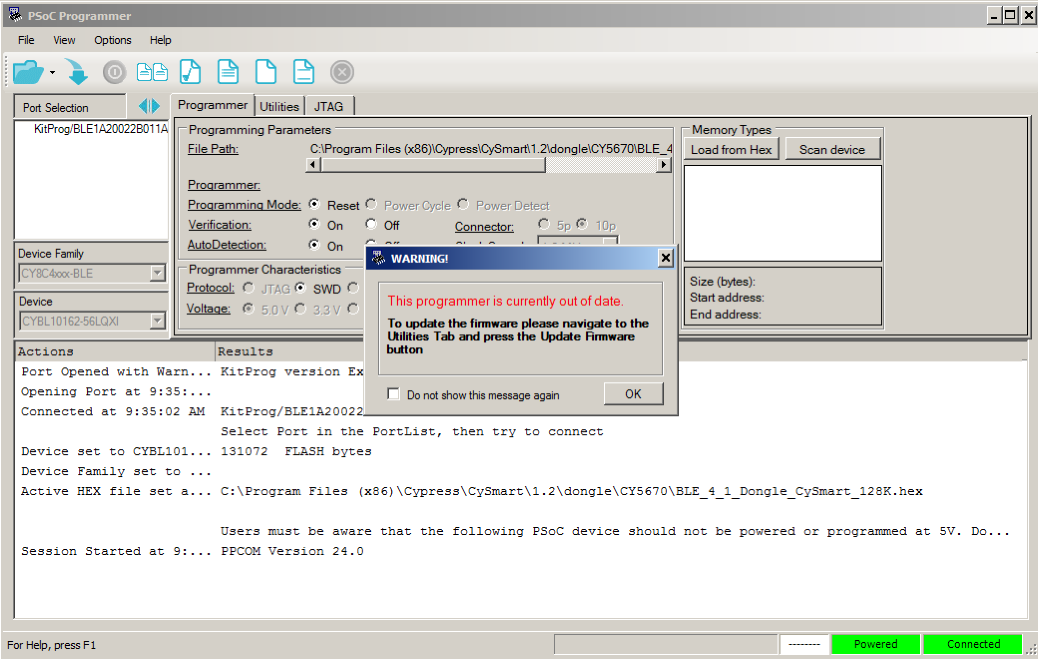
In order to fix the firmware, you need to quit the CySmart program, then start the PSoC Programmer software. And, I also find that every time I start PSoC Programmer that the KitProg firmware is out of date. To fix this press OK.
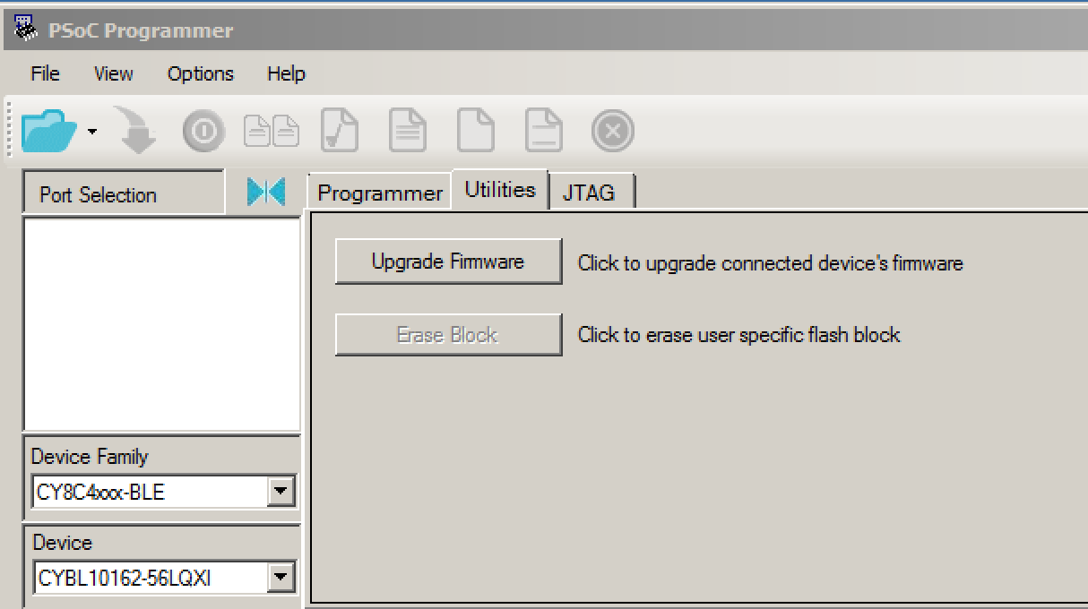
Then click the “Utilities” tab, then “Upgrade Firmware”
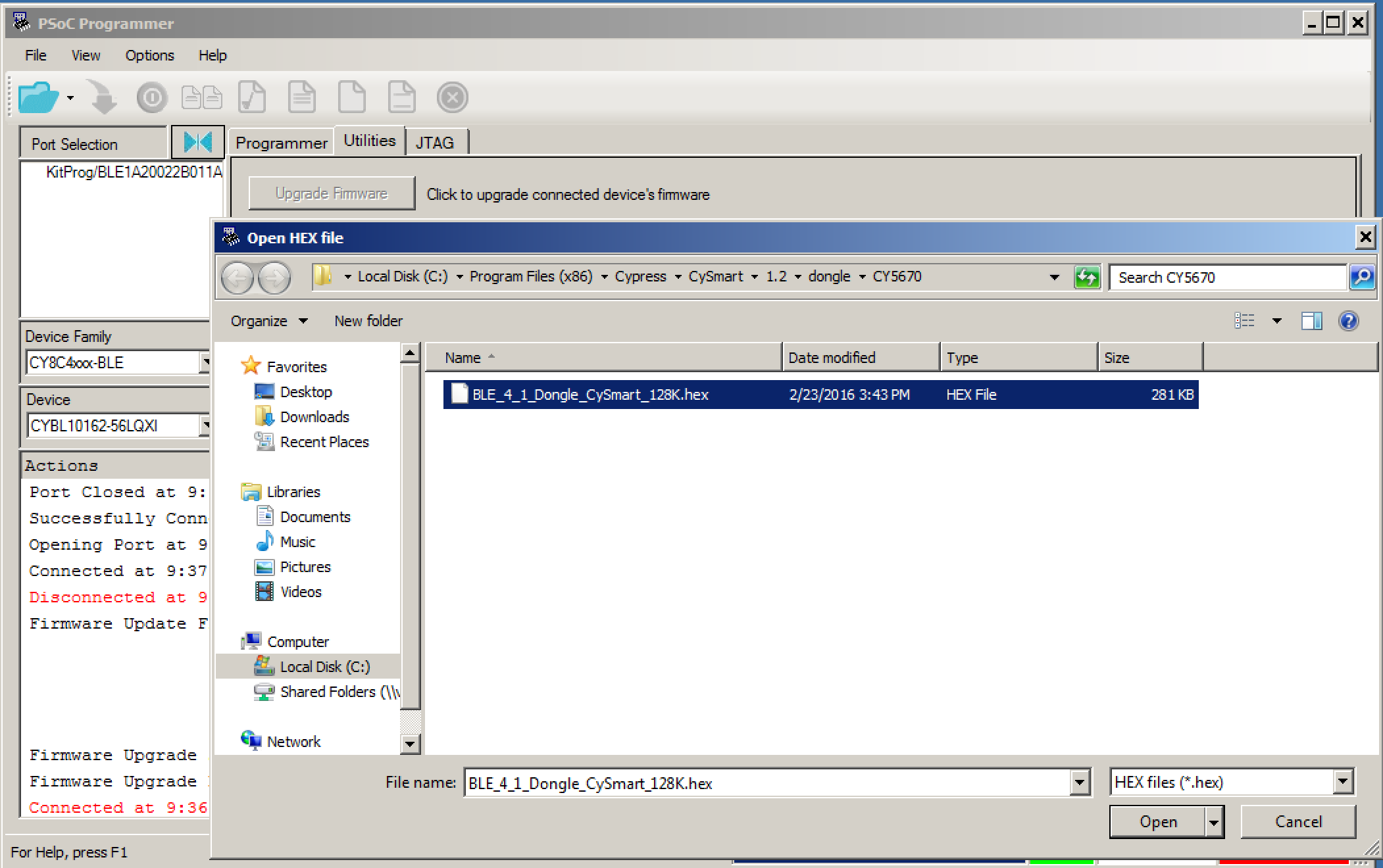
Once the KitProg firmware is up to date, you can then program the CySmart firmware. Press the “folder” button, then navigate to the firmware which lives in Program Files(x86) –> CySmart –> 1.2 –> dongle –> CY5670. Then press the “down arrow” which means “download the firmware”. Once that is done, you are good to go with running CySmart (quit PSoC programmer so that it can talk to the dongle).
Use the PC CySmart to Debug a PSoC4 BLE Peripheral
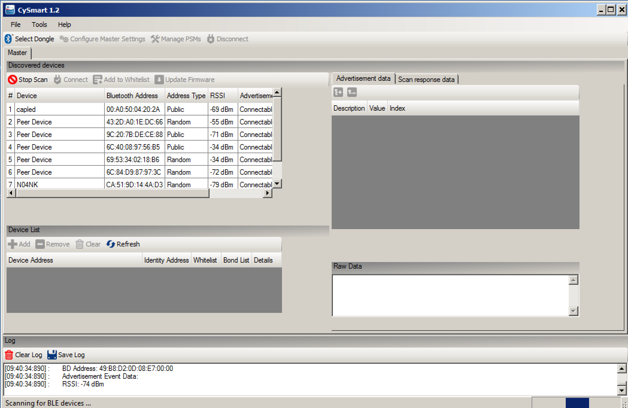
Now that I have a functional CySmart dongle, I can run CySmart. This is a Windows PC Version of a GATT browser (like the CySmart iOS/Android App or the LightBlue app that I used in the previous article). In CySmart press “Start Scan”. In the picture below you can see all of the BLE peripherals that CySmart can see, including the “capled” project.
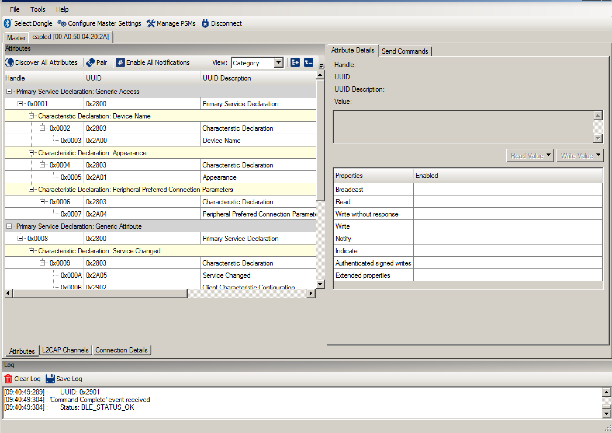
Once I click on “capled” and then “connect” and finally “discover all attributes” I will get a window that looks like this. You can see all of the GATT Database.
After that I can Read and Write attributes (like the LED Attribute) by typing the value I want to write into the box on the upper right, and pressing “Write Value”. For example you can turn on the LED by writing a “1” into the LED characteristic.
Modify the PSoC4 BLE Central Project to work on the CySmart Dongle
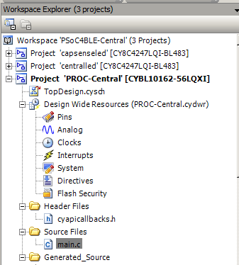
Next, lets modify the original project so that it can work on the dongle. I will start this whole process by doing a copy/paste of the “centralled” project. Then renaming it to “PROC-Central”
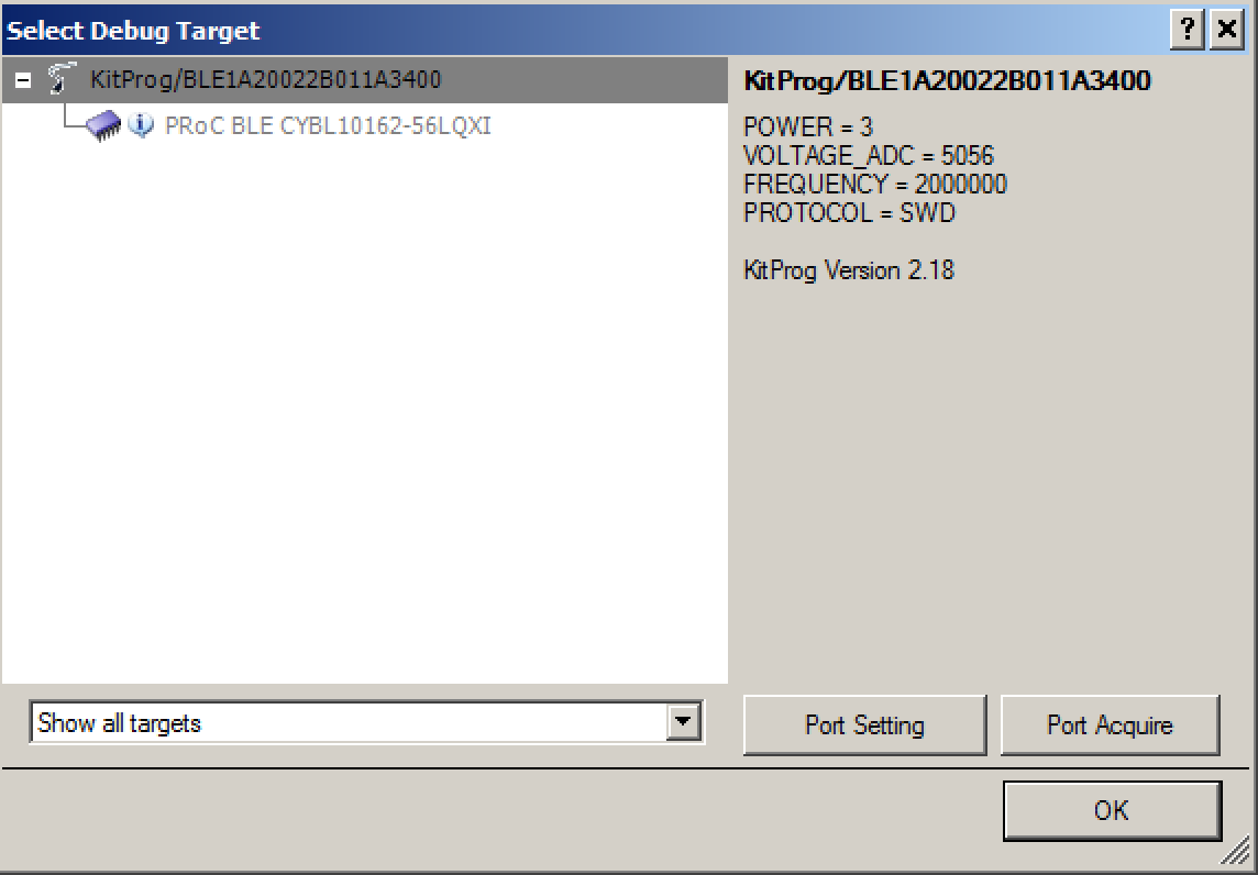
The dongle has a PRoC instead of a PSoC4 BLE. This means you need to run the device selector and change the target device. I can never remember which version of PROC is on the dongle. So, to figure it out I click the program button, which brings up this screen that says my project isn’t compatible with the target. It also tells me that this dongle has “CYBL10162-56LQXI”
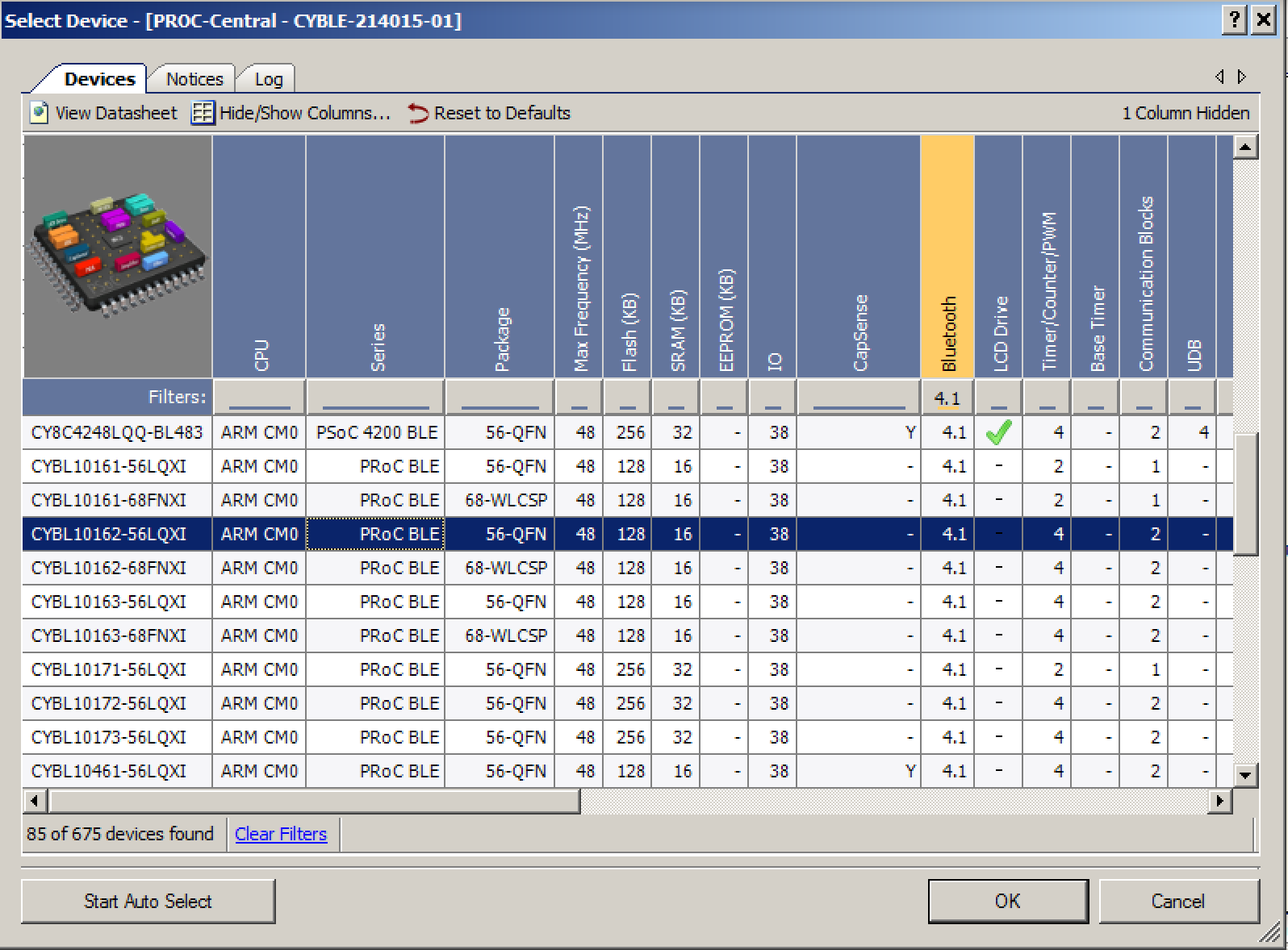
Now go to “Project –> Device Selector” and change to the “CYBLE10162-56LQXI”
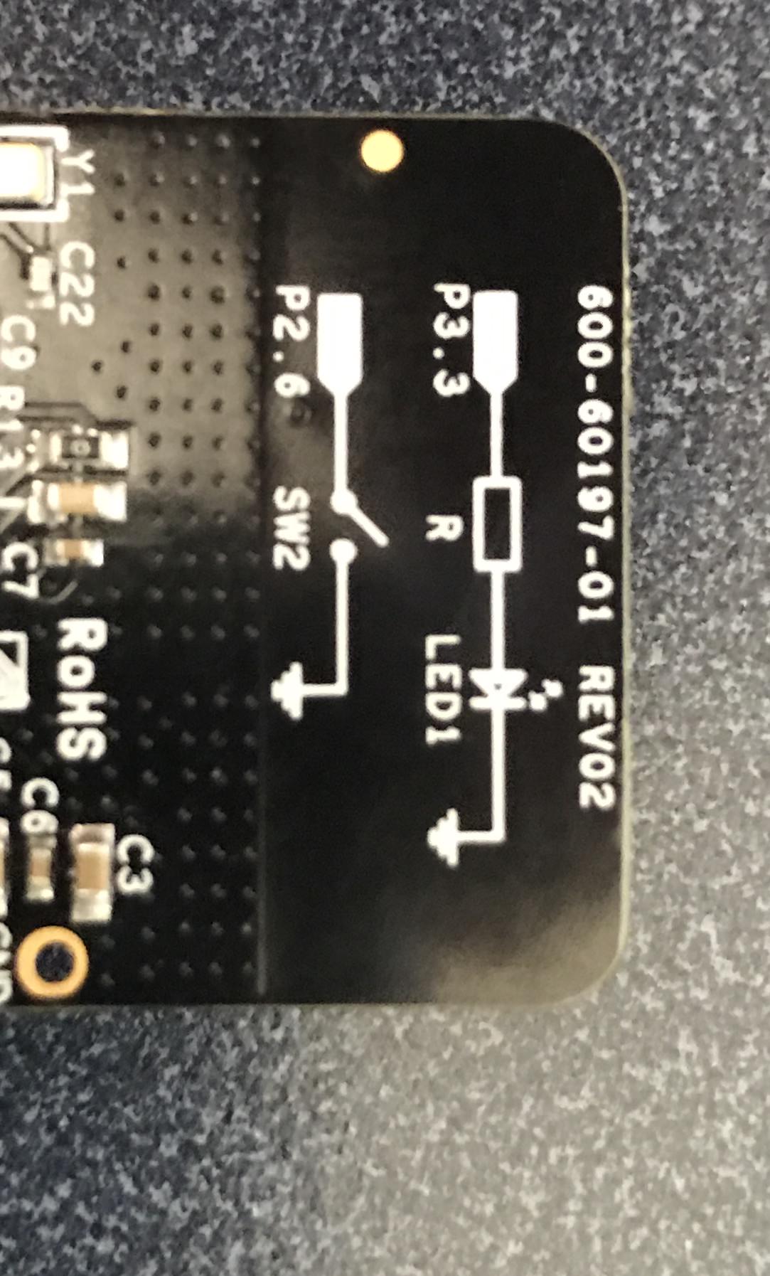
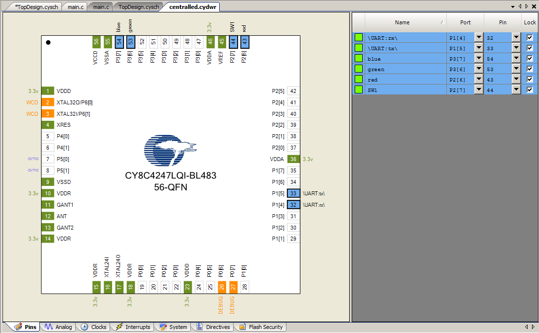
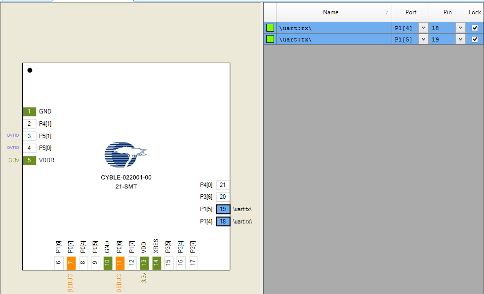
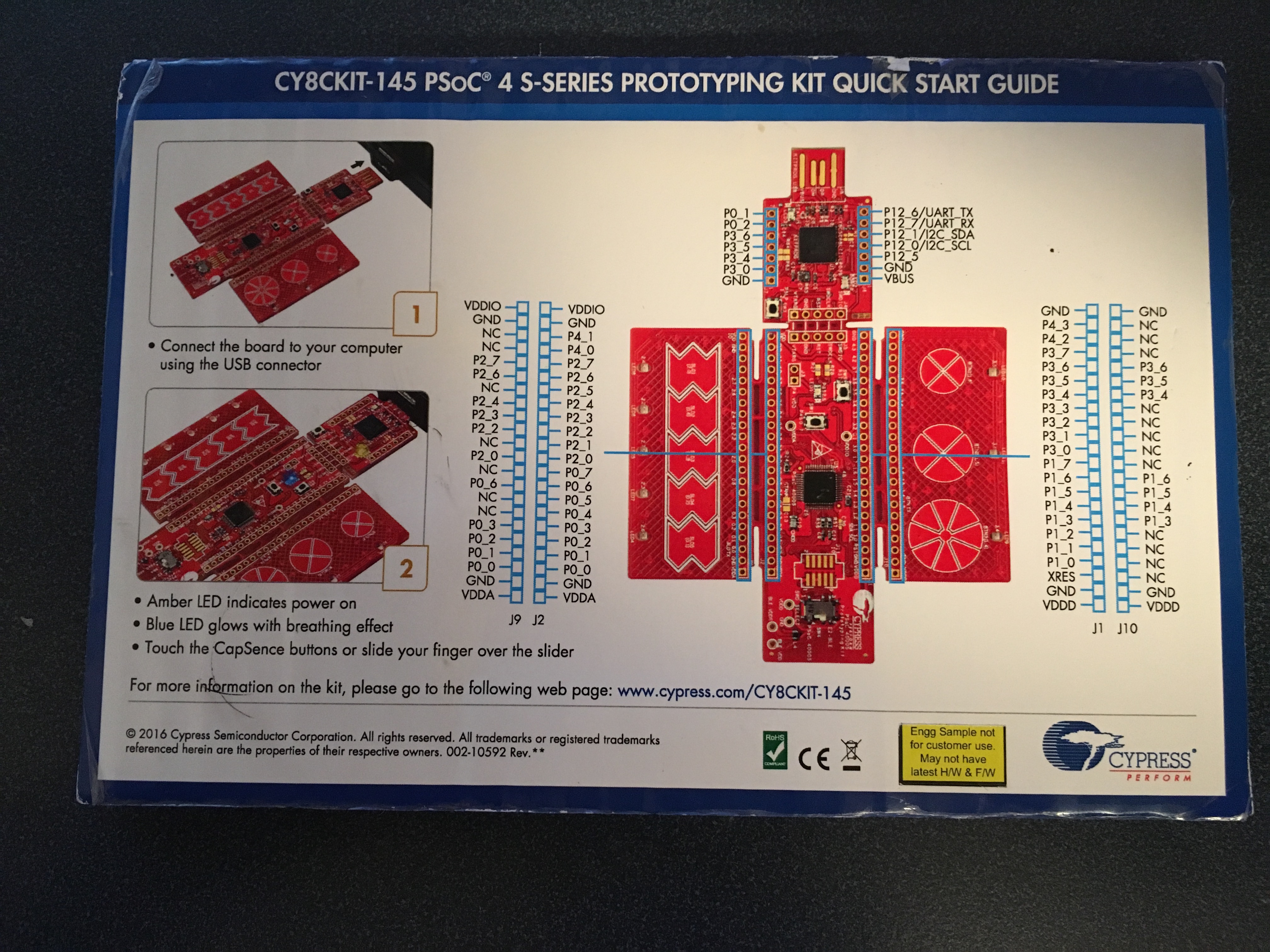
The pin assignments are a little bit different. On the back of the board you can see that we put a handy-dandy picture showing the arrangement for the LED and the button.
But unfortunately we didn’t show you the pins for the UART on the silkscreen. But you can find those in the schematic (which can be downloaded from the website)
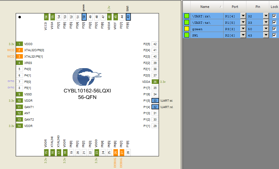
Now you can assign the correct pins (noticed that I deleted the red/blue LED pins because they don’t exist on the dongle)
Finally you need to change the PWM to be active high instead of active low.
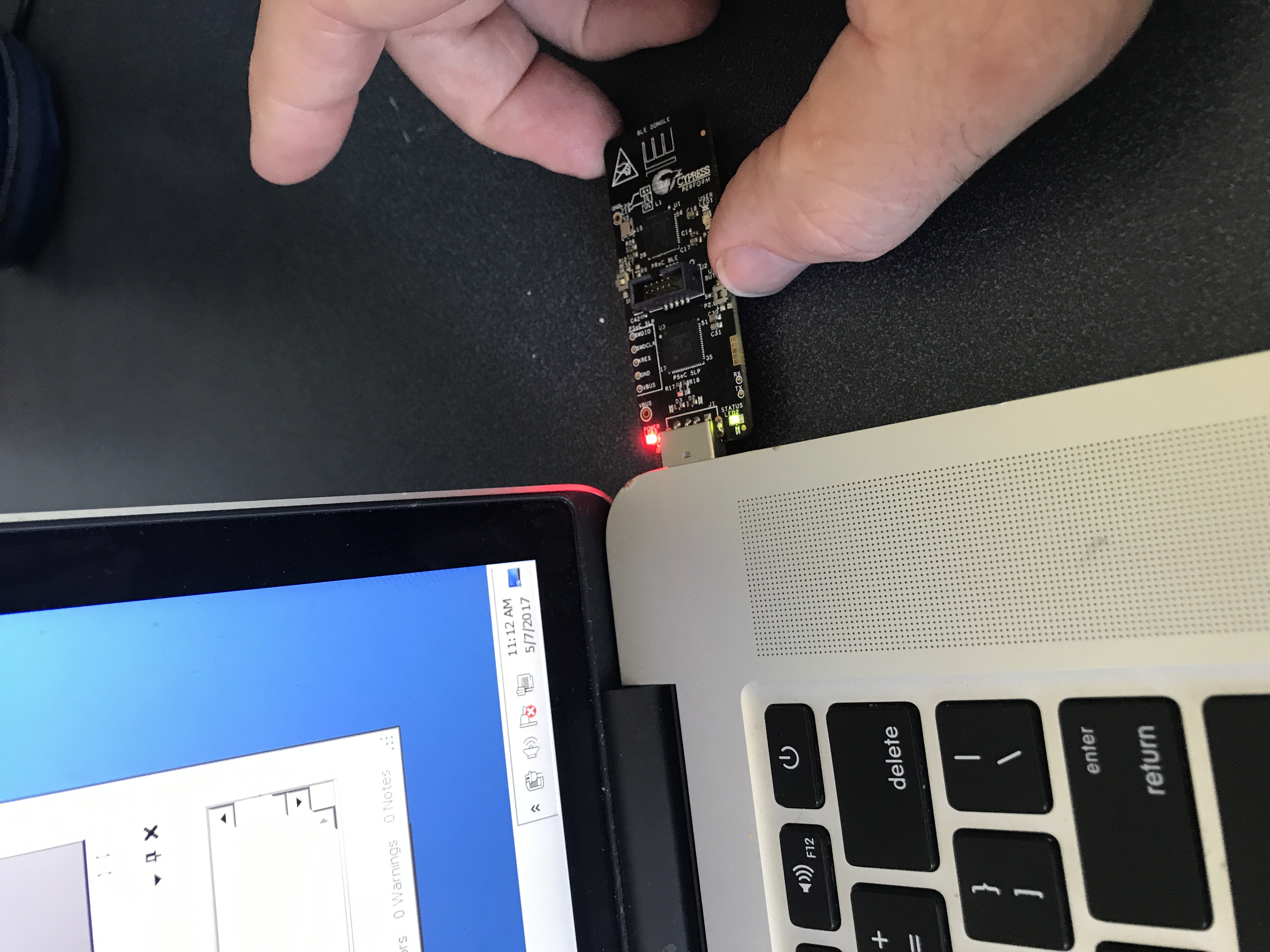
Now program and test it. The user switch is the tiny little button under my thumb.
As with the previous article you can find all of this source code on the IoT Expert Github site or git@github.com:iotexpert/PSoC4BLE-Central.git. In the next article I will start the process of building a GATT Browser inside of a PSoC4 BLE.
Last week I got a nice email from a Cypress customer in Italy (I think). He asked about implementing a PSoC4 BLE Central. I replied that it was pretty easy. Over the weekend I thought about it a little bit more and realized that I had never implemented the Central a.k.a. the “other” side of a BLE connection in a PSoC. I had always built the Central side in an iPhone application written in Swift or Android application written in Java. So it seemed like a good thing to do to implement it in C. It turned out to not be quite as easy I had hoped because of some problems in the Cypress documentation. In the next several articles I am going to show you how to implement a PSoC4 BLE Central.
I am going to use the project from the video series called “capsenseled” as the GAP Peripheral and then I am going to show you how to write the GAP Central code. You can learn about the GAP Peripherals in the video series called “PSoC® 4 BLE 101 Video Tutorial Series: How To Create Products Using PSoC 4 BLE“. Here is the first video from YouTube.
In that series of videos I showed you how to build a custom GATT profile for Capsense and an LED. The GAP Peripheral has an LED that you can control from the GAP Central, and it has a Capsense slider that you can read its value from the GAP Central. You can “git” all of the source for this project from the IoTExpert Github website or git@github.com:iotexpert/PSoC4BLE-Central.git
In this article I will show you:
The GAP Peripheral and GATT Database
How to build the schematic for the GAP Central
How to configure the BLE component for the GAP Central functionality
The steps required in the firmware to read and write the GAP Peripheral
The GAP Peripheral and GATT Database
To start the process I will “git” the source code for this GAP Peripheral from the IOT Expert Github site. Then, I open the project called “capsenseled” in PSoC Creator. The schematic has:
The Capsense component which controls the slider
A PWM that drives the blue LED to serve as a notification of the state of the BLE (blinking means advertising)
A red LED which can be turned on/off from the GAP Central Side
The BLE Component
The BLE Component is configured to be:
A GAP Peripheral
with a GATT Server
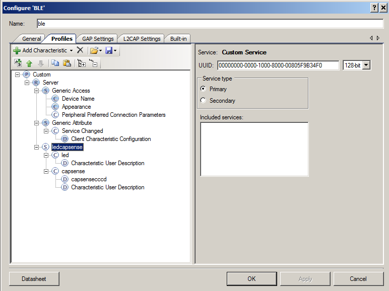
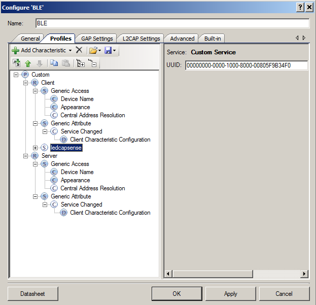
The GATT Database is setup to have:
A custom service called “ledcapsense”
A custom characteristic called “led” (a uint8)
A custom characteristic called “capsense” (a uint16)
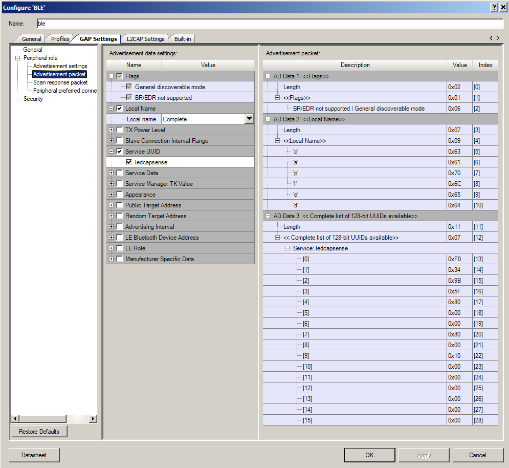
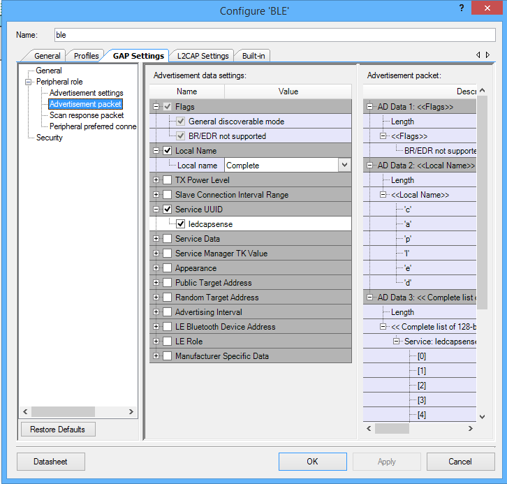
The advertising packet is setup to advertise
The name of the device “capled”
The fact that it has a GATT Service called “ledcapsense”
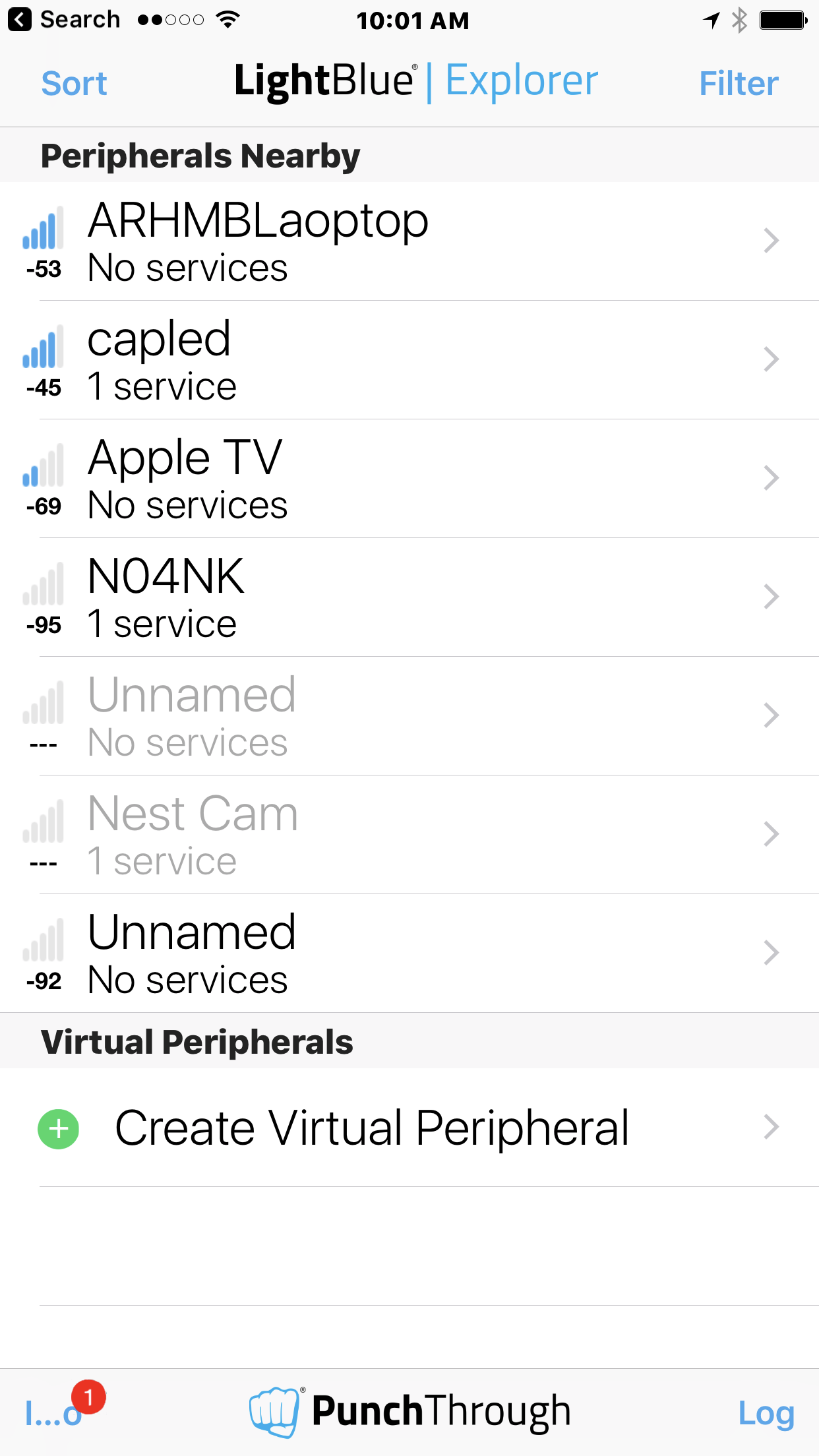
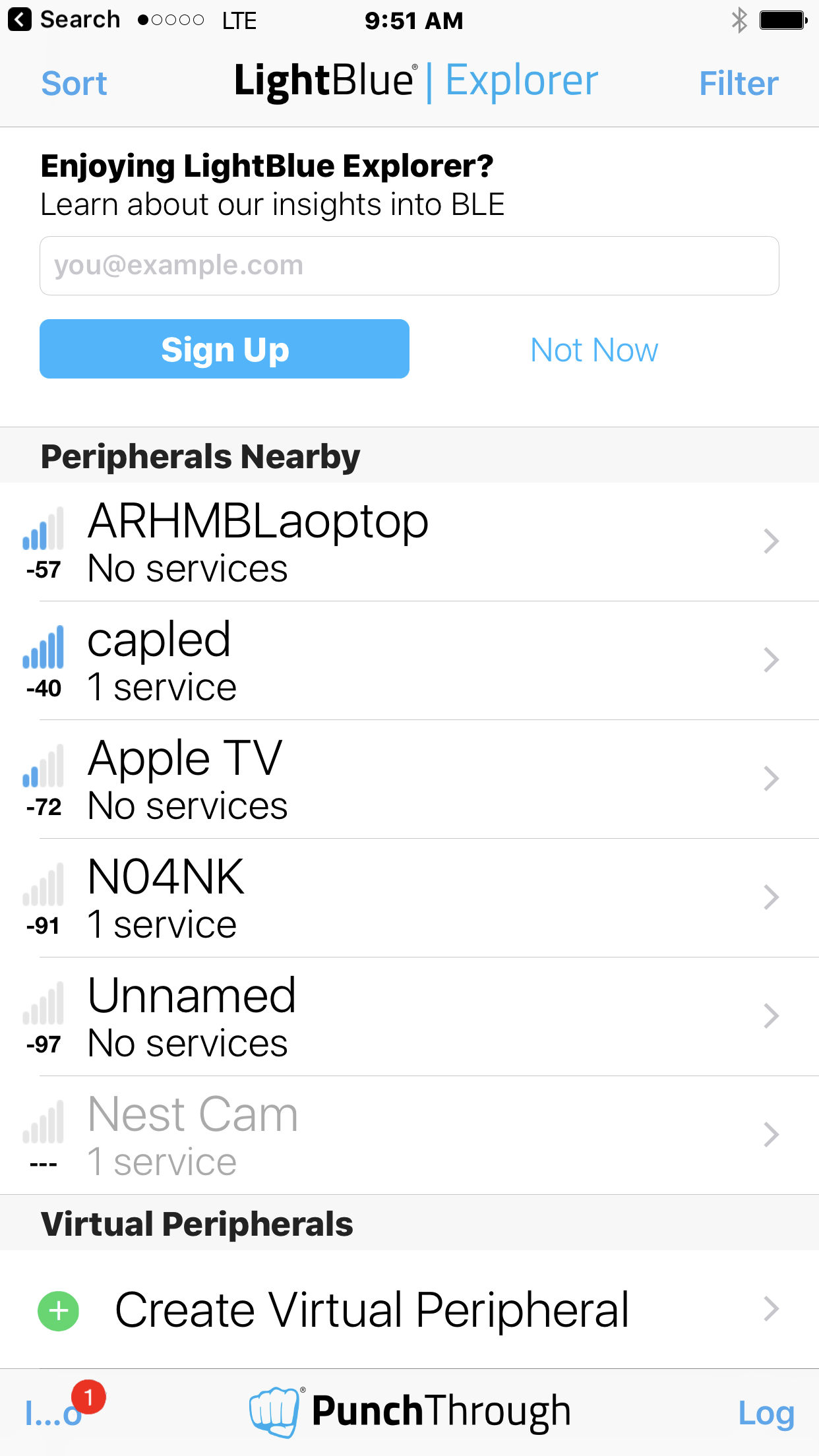
When you program this project you will get a blinking blue LED (that says the BLE is advertising). When I run “lightblue” I can see the “capled” advertising:
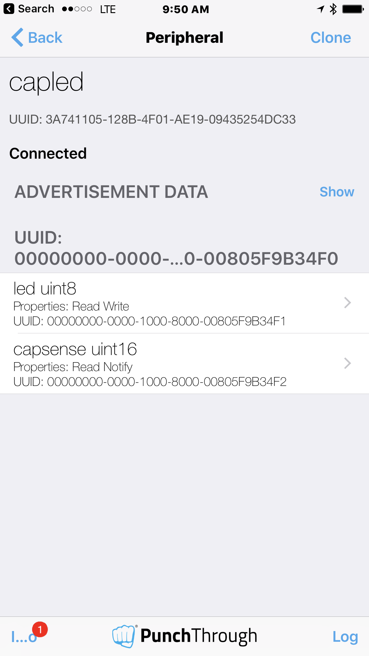
After I connect the device I can see the UUID of the custom service & the two characteristics:
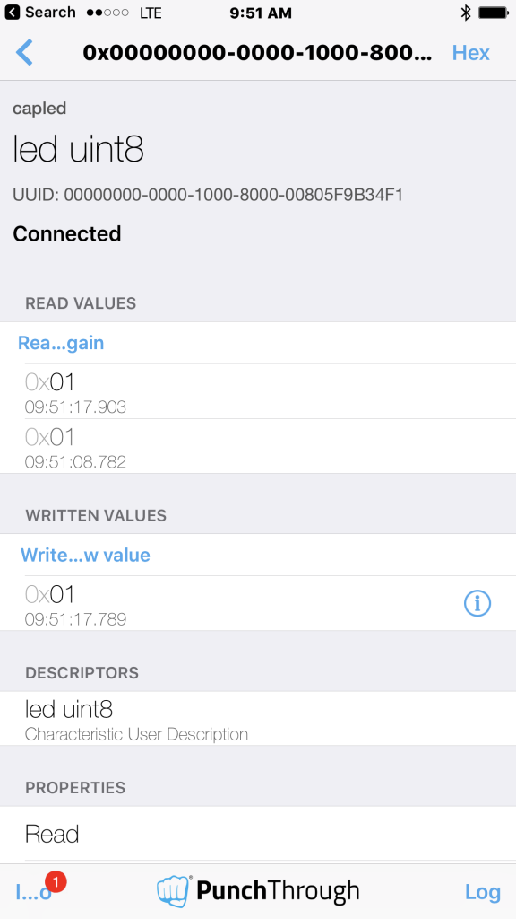
Finally I can read/write the led characteristic.
PSoC4 BLE Central Schematic
To make my PSoC4 BLE Central I build a project for the CY8CKIT-042-BLE (you can see all of the source code in the project called “centralled”
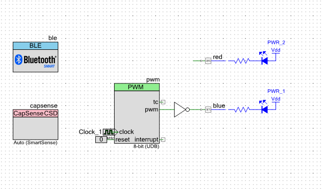
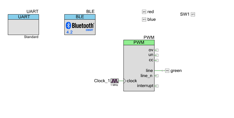
Start by building a schematic with
A debug UART (I will print to the terminal program)
The red/blue/green led pins
The mechanical button pin (called SW1)
A PWM to drive the green LED (it will vary the brightness of the LED based on the capsense value on the GAP Peripheral)
The BLE Component
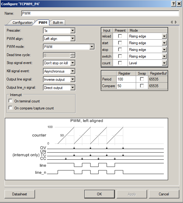
Configure the PWM (to vary between 0 and 100% brightness) with inverted logic (because the LED on the board is active low)
Assign the Pins:
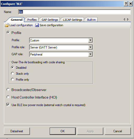
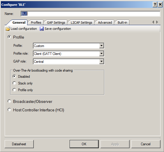
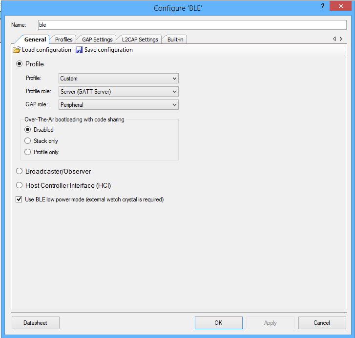
You will need to configure the BLE to be a:
A GATT Client
A GAP Central
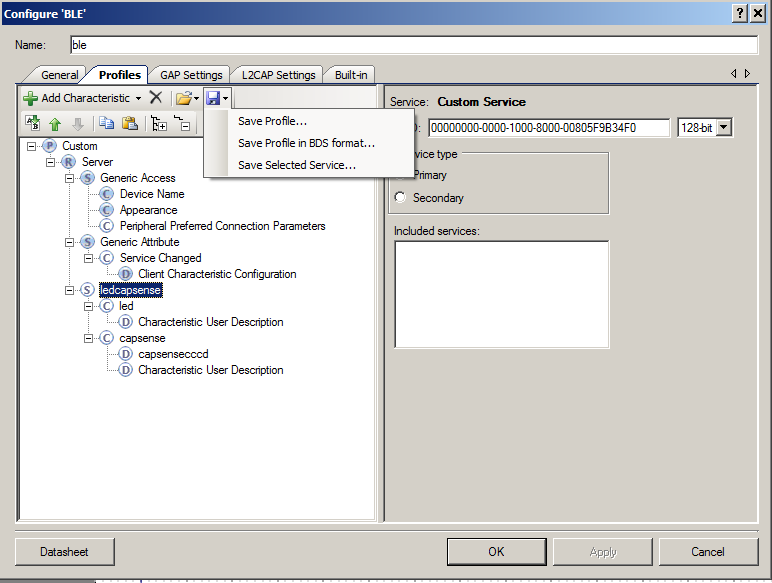
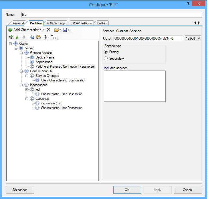
If you tell the BLE Component what the GATT Server configuration looks like (on the GAP Peripheral side) it will make the service discovery firmware much simpler. To do this, go to the GAP Peripheral project and export the “ledcapsense” service from the Peripheral into an xml file (see the Save Selected Service…)
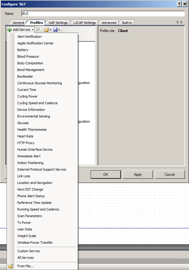
Then go back to your PSoC4 BLE Central project and add a new service “From file” (see at the bottom of the menu)
After all that you will end up with something that looks like this. You can see the “ledcapsense” service is listed under the “client” section of the GATT configuration.
PSoC4 BLE Central Firmware
The firmware for the PSoC4 BLE Central needs to:
Initialize the PSoC
Scan for GAP Peripherals that are advertising the “ledcapsense” service
Connect to the GAP Peripheral & Discover its services
Turn on notifications for the Capsense characteristic
Loop
If the users changes the state of the button then send over a LED on/off
If you receive a notification of a change in capsense then update the PWM Compare value (to change the intensity)
Most of the Cypress BLE APIs will create an “event” that you will need to process in the BLE loop. The interesting events are:
Event
Description
CYBLE_EVT_STACK_ON
The BLE Stack has turned on and you can start advertising
CYBLE_EVT_GAP_DEVICE_DISCONNECTED
The GAP Peripheral you were attached to has disconnected. Start scanning for another GAP Peripheral to attach to
CYBLE_EVT_GAP_DEVICE_CONNECTED
You have successfully completed a connection to a GAP Peripheral
CYBLE_EVT_GAPC_SCAN_PROGRESS_RESULT
You received an advertising packet from a GAP Peripheral
CYBLE_EVT_GAPC_SCAN_START_STOP
You either stopped or started scanning for advertising packets from GAP Peripherals
CYBLE_EVT_GATT_CONNECT_IND
The GATT Connection is complete. This event occurs before the CYBLE_EVT_GAP_DEVICE_CONNECTED EVENT so you don't need to do anything
CYBLE_EVT_GATTC_DISCOVERY_COMPLETE
The service discovery is complete. You can now set the CCCD and turn on the PWM
CYBLE_EVT_GATTC_HANDLE_VALUE_NTF
You received a notification of a change in the Capsense from the GAP Peripheral.
CYBLE_EVT_GATTC_WRITE_RSP:
Your write succeeded. For this application there is nothing to do
To make all of this work, I created a state machine using an enumerated datatype.
// Modes for a statemachine
typedef enum SystemMode {
    SM_INITIALIZE,          // Startup state
    SM_SCANNING,            // Looking for a Peripheral
    SM_CONNECTING,          // I have issued connected and waiting for it to complete
    SM_SERVICEDISCOVERY,    // Started the service discovery and waiting for it to complete
    SM_CONNECTED            // Connection complete...
} SystemMode_t;

static SystemMode_t systemMode = SM_INITIALIZE; // Starting mode of statemachine
1. Initialize the PSoC4 BLE Central
The project starts with the normal turn on the PSoC components and stuff.
int main(void)
{
    CyGlobalIntEnable; /* Enable global interrupts. */
    UART_Start();
    PWM_Start();
    CyBle_Start( CyBle_AppCallback );
2. Scan for Peripherals that are advertising the “ledcapsense” service
Most everything that happens in the BLE sub-system triggers a callback to your “AppCallback” which you registered when you started up the BLE component. The AppCallback has two parameters, which event and a generic void* style argument which can be one of a bunch of things.
(Lines 73-79) After you turn on the power to your central and the BLE subsystem you will need to start scanning for peripherals that are advertising. To do this you call “CyBle_GapcStartScan”. The “Gapc” part of the API name means GAP Central. The other time you need to start scanning is when you have been disconnected.
(Lines 81-93) When you receive an advertising packet you can look in the packet and figure out if it is a GAP Peripheral that you want to attach too. In this case I:
Only look at packets that are 29 bytes long (which I looked up in the BLE GAP Peripheral project)
And.. if the packet has the UUID of the capsenseled service
Then I save the Bluetooth Device Address (BD address) and stop scanning. When the scanning is stopped the BLE subsystem will issue and event called “CYBLE_EVT_GAPC_SCAN_START_STOP” (the next section)
       case CYBLE_EVT_STACK_ON:
        case CYBLE_EVT_GAP_DEVICE_DISCONNECTED:
            systemMode = SM_SCANNING;
            enabledCapsenseNotifications = 0;
            CyBle_GapcStartScan(CYBLE_SCANNING_FAST); // Start scanning for peripherals
            PWM_WriteCompare(0); PWM_Stop();          // Turn off the LED
        break;

        CYBLE_GAPC_ADV_REPORT_T* scanReport;
        case CYBLE_EVT_GAPC_SCAN_PROGRESS_RESULT:                     // Advertising packet
            scanReport = (CYBLE_GAPC_ADV_REPORT_T*)eventParam;
            if(scanReport->dataLen != 29)                             // Number of bytes in ledcapsense advertising packet
                break;
            if(memcmp(&CapLedService,&scanReport->data[11],sizeof(CapLedService))) // if service is in packet
                return;

            // Setup for the connection
            remoteDevice.type = scanReport->peerAddrType;          // setup the BD addr
            memcpy(&remoteDevice.bdAddr,scanReport->peerBdAddr,6); // 6 bytes in BD addr
            systemMode = SM_CONNECTING;
            CyBle_GapcStopScan();                                  // stop scanning for peripherals

        break;
3. Connect to the Peripheral & Discover the Services
(lines 97-100) When the BLE either starts or stops scanning it issues the “CYBLE_EVT_GAPC_SCAN_START_STOP” event. I use the state machine to determine what to do. Basically if the mode of my system is “SM_CONNECTING” then I attempt to make a connection to the remote device.
(lines 102-105) Once the device is connected you need to do a service discovery to find out what services are on the GAP Peripheral and more importantly what are the handles of the characteristics. The CyBle_GattcStartDiscovery issues requests to the GAP Peripheral to tell the services and characteristics on the peripheral, to which it responds with events. Cypress provides code in BLE_custom.h and BLE_custom.c to process those responses. Once the discovery is complete you are then ready to talk to the device.
        case CYBLE_EVT_GAPC_SCAN_START_STOP: // If you stopped scanning to make a connection.. then launch connection
            if(systemMode == SM_CONNECTING )
                CyBle_GapcConnectDevice(&remoteDevice);
        break;

        case CYBLE_EVT_GAP_DEVICE_CONNECTED:              // Connection request is complete
            CyBle_GattcStartDiscovery(cyBle_connHandle);  // Discover the services on the GATT Server
            systemMode = SM_SERVICEDISCOVERY;
        break;
4. Turn on notifications for the Capsense characteristic
We are interested in getting notified when the Capsense characteristic on the GAP Peripheral changes. To enable getting a notification you need to write a “0x01” into the Client Characteristic Configuration Descriptor or CCCD. In order to accomplish this you need to know the handle of that descriptor. The handle is discovered automatically by the BLE_custom.c functions. If you look in BLE_custom.h you will find #define(s) that are the indexes of the things you need to know from the service discovery array.
/* Below are the indexes and handles of the defined Custom Services and their characteristics */
#define CYBLE_CUSTOMC_LEDCAPSENSE_SERVICE_INDEX   (0x00u) /* Index of ledcapsense service in the cyBle_customCServ array */
#define CYBLE_CUSTOMC_LEDCAPSENSE_LED_CHAR_INDEX   (0x00u) /* Index of led characteristic */
#define CYBLE_CUSTOMC_LEDCAPSENSE_LED_CHARACTERISTIC_USER_DESCRIPTION_DESC_INDEX   (0x00u) /* Index of Characteristic User Description descriptor */
#define CYBLE_CUSTOMC_LEDCAPSENSE_CAPSENSE_CHAR_INDEX   (0x01u) /* Index of capsense characteristic */
#define CYBLE_CUSTOMC_LEDCAPSENSE_CAPSENSE_CAPSENSECCCD_DESC_INDEX   (0x00u) /* Index of capsensecccd descriptor */
#define CYBLE_CUSTOMC_LEDCAPSENSE_CAPSENSE_CHARACTERISTIC_USER_DESCRIPTION_DESC_INDEX   (0x01u) /* Index of Characteristic User Description descriptor */
To set the CCCD you create a “CYBLE_GATTC_WRITE_REQ_T” and fill it in with the information required. Specifically, the value and the handle which you find on line 57. Then you write it to the GAP Peripheral.
/***************************************************************
 * Function to set the Capsense CCCD to get notifications
 **************************************************************/
void updateCapsenseNotification()
{
    CYBLE_GATTC_WRITE_REQ_T 	tempHandle;
    uint8 cccd=1;
    enabledCapsenseNotifications = 1;

    tempHandle.attrHandle = cyBle_customCServ[CYBLE_CUSTOMC_LEDCAPSENSE_SERVICE_INDEX]
    .customServChar[CYBLE_CUSTOMC_LEDCAPSENSE_CAPSENSE_CHAR_INDEX]
    .customServCharDesc[CYBLE_CUSTOMC_LEDCAPSENSE_CAPSENSE_CAPSENSECCCD_DESC_INDEX].descHandle;

  	tempHandle.value.val = (uint8 *) &cccd;
    tempHandle.value.len = 1;

    CyBle_GattcWriteCharacteristicValue(cyBle_connHandle,&tempHandle);
}
5. Main Loop
The main look is simple. Basically if you are in the SM_CONNECTED state, then call the function which updates the state of the Remote LED.
   for(;;)
    {
        switch(systemMode)
        {
            case SM_INITIALIZE:
            case SM_SCANNING:
            case SM_CONNECTING:
            case SM_SERVICEDISCOVERY:
            break;
            case SM_CONNECTED:
                updateLed();
            break;
        }

        CyBle_ProcessEvents();
        CyBle_EnterLPM(CYBLE_BLESS_DEEPSLEEP);
    }
}
5. Main Loop (Write the state of the LED)
This function looks at the state of the switch, then if it has changed, sends the updates state to the Peripheral. The switch is active low (a 0 means that it is pressed) but we want a “1” to mean turn on the LED.
Just like the updateCapsenseNotification() function, you look in the cycle_customCServ array to find the handle of the LED characteristic.
/***************************************************************
 * Function to update the LED state in the GATT database
 * Based on state of swtich
 **************************************************************/
void updateLed()
{
    static int previousState = 10;       // The first time it is called send the data
    uint8 state;                         // A place to hold the state of the switch
    CYBLE_GATTC_WRITE_REQ_T tempHandle;  // A handle to call the BLE API

    state = !SW1_Read();                 // Active low switch
    if(state == previousState)           // If nothing has changed dont send anythign
        return;

    previousState = state;
    tempHandle.attrHandle = cyBle_customCServ[CYBLE_CUSTOMC_LEDCAPSENSE_SERVICE_INDEX]
        .customServChar[CYBLE_CUSTOMC_LEDCAPSENSE_LED_CHAR_INDEX]
        .customServCharHandle;

  	tempHandle.value.val = (uint8 *) &state;
    tempHandle.value.len = 1;

    CyBle_GattcWriteCharacteristicValue(cyBle_connHandle,&tempHandle);
}
5. Main Loop (Capsense Notifications)
The last bit of code updates the state of the PWM driving the LED when you get a notification from the GAP Peripheral that it has been updated.
        CYBLE_GATTC_HANDLE_VALUE_NTF_PARAM_T *capsenseNTF;
        case CYBLE_EVT_GATTC_HANDLE_VALUE_NTF:                                 // Capsense Notification Recevied
            capsenseNTF = (CYBLE_GATTC_HANDLE_VALUE_NTF_PARAM_T *)eventParam;
            if(capsenseNTF->handleValPair.value.val[0] == 0xFF)                // Turn off the LED in no touch
                PWM_WriteCompare(0);
            else
                PWM_WriteCompare(capsenseNTF->handleValPair.value.val[0]);
        break;

        case CYBLE_EVT_GATTC_WRITE_RSP: // Sucesfull write - nothing to do
        break;
In the next Article(s) I will show you how to use the CySmart dongle. I am also planning on showing you the firmware to create a GATT Browser.
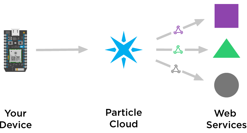
In the previous article I showed you all of the components of the Particle Photon Ecosystem. All that is cool. But what can you build? I have written extensively about the Elkhorn Creek in my backyard, and the system that I built to monitor the water level. As part of that series of articles I explained that I have a 4-20ma current loop that turns pressure into water level read here . In this article I will:
Attach the Photon to my Creek System Current Loop
Write the Firmware in the Particle Cloud IDE to publish W
Send events to the Particle Cloud & monitor
Use Webhooks to send the data to ThingSpeak.com
Attach Particle Photon to Creek System
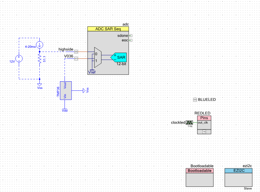
To interface to a 4-20mA current look you just attach it to a 51.1 ohm resistor to serve as a trans-impedence amplifier. Here is the PSoC Creator schematic for the board: Using this schematic, the system will generate a voltage between (51.1 Ohms * 4ma = 204.4mV) and (51.1Ohm * 20mA = 1022 mV). This voltage can then be attached to an Analog To Digital Convertor, then converted digitally into a Pressure, then a water depth.
I decided that the easiest thing to do with the Particle Photon was to attach the pin A0 to the highside input. This was easy as I put a loop on the Creek Board. The loop is labeled “PRES”. The picture is a bit ugly as I was standing in the dark in the rafters of my barn. Sorry.
Particle Photon Firmware
When you look at the main loop of the firmware, lines 23-40 it does three things
Reads the ADC voltage on Pin A0
Applies an Infinite Impulse Response Filter (IIR) with coefficients of 7/8 and 1/8. This is low pass filter.
Turns the voltage into depth. This is done by turning (4-20ma) into (0-15 psi) then PSI into Feet
Then, on lines 34-39, I use the system time to figure out if it is time to publish again. I publish every “INTERVAL”.
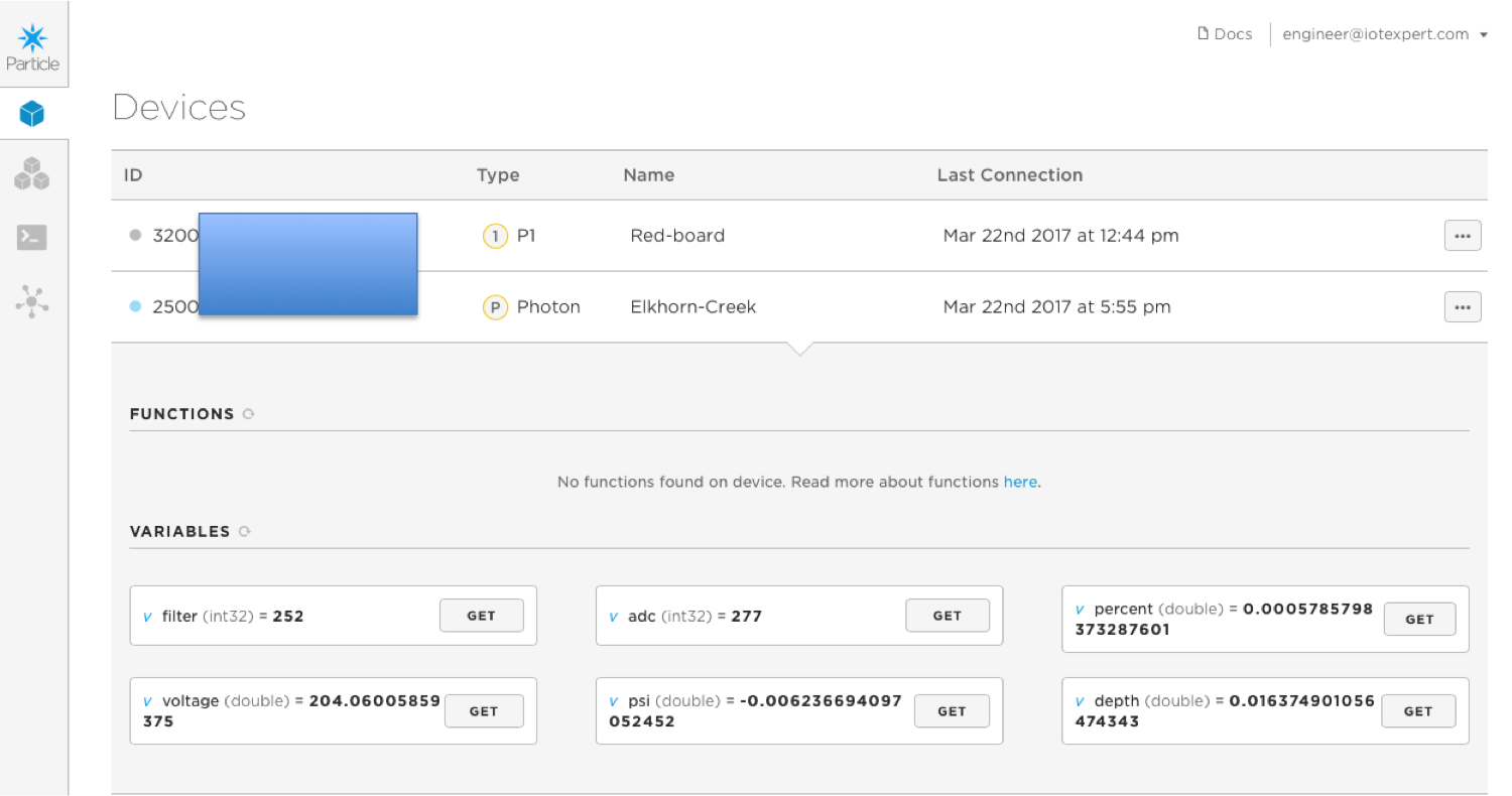
In order to test the Particle Cloud interface to the Photon, I setup all of the intermediate calculation of depth as “Particle.variable”s which allows me to inspect them remotely.
uint32_t nextTime; // when do you want to publish the data again
const uint32_t INTERVAL = (5*60*1000); // every 5 minutes in milliseconds
const double  MVPERCOUNT = (3330.0/4096.0); // 3300mv and 2^12 counts
uint32_t current;
uint32_t filter=0;
double depth;
double percent;
double psi;
double voltage;
double percentTemp;

void setup() {
    nextTime =  millis() + INTERVAL;
    // setup variables so that they can be polled
    Particle.variable("filter",filter);
    Particle.variable("adc",current);
    Particle.variable("percent",percent);
    Particle.variable("voltage",voltage);
    Particle.variable("psi",psi);
    Particle.variable("depth",depth);
}

void loop() {

   char buff[128];

    current = analogRead(A0);
    filter = ((filter>>3) * 7) + (current>>3); // IIR Filter with 7/8 and 1/8 coeffecients
    voltage  = ((double)filter) * MVPERCOUNT; // Convert ADC to Milivolts
    percent = ( voltage - (51.1*4.0) ) / (51.1 * (20.0-4.0)); // 51.1 ohm resistor... 4-20ma
    psi = percent * 15.0; // Range of pressure sensor
    depth = psi / 0.53; // Magic 0.53psi per foot

   if(millis() > nextTime)
   {
        sprintf(buff,"%.1f",depth);
        Particle.publish("CreekDepth",buff);
        nextTime = millis() + INTERVAL;
   }
}
Sending Events to the Particle Cloud & Monitor
Once I flashed the firmware with the very cool Over-The-Air Bootloader, I go to the Particle Console and click on my device. As soon as I do that I see the “Particle.variable”s that I defined in the firmware. One by one I press “get” and after a second the data is displayed on the screen. I am not exactly sure how the exactly works, but it is cool.
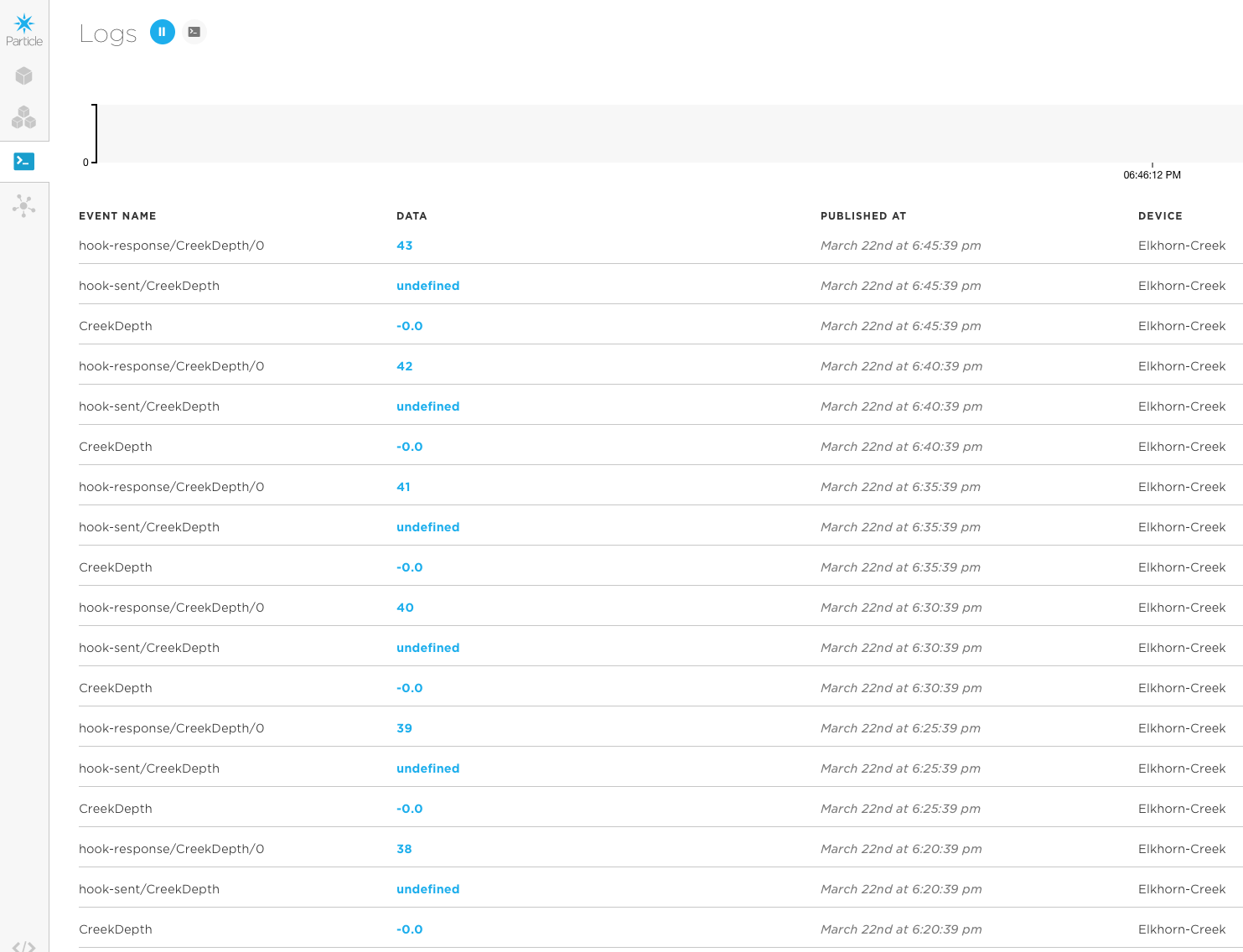
After inspecting the variables, I go the Logs page and look to see what the events are. You can see that every 5 minutes (about) there is an event called “CreekDepth” with a -0.0 or so. That is good as it means that the Particle Photon is publishing regularly. The answer is 0.0 (or about 0.0) as the Elkhorn Creek if not doing anything right now. The other events are part of the web hook that I setup (and will talk about in the next section).
Using WebHooks to send data to ThingSpeak.com
Unless I am missing something, the Particle Cloud does not store your actual data. They do have a mechanism to take Events from your devices and trigger a “WebHook”. This is basically a RESTFul API call to another cloud.
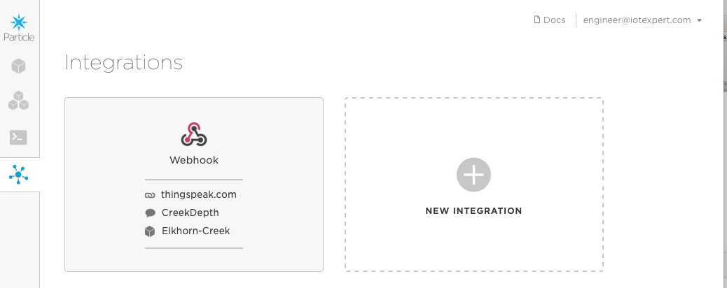
They call these “integrations” and you configure them on the Console. When you press “Integrations” you end up with this screen which gives you the option of editing a current webhook or creating a new one.
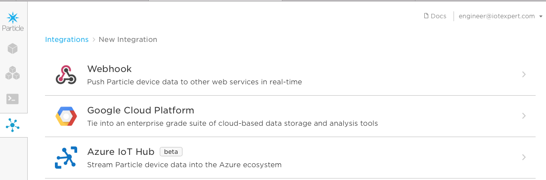
When you click on “new integration” it gives you the option of connecting to Google, Microsoft Azure or Webhook. I havent tried Google or Azure so for this article Ill stick with a Webhook.
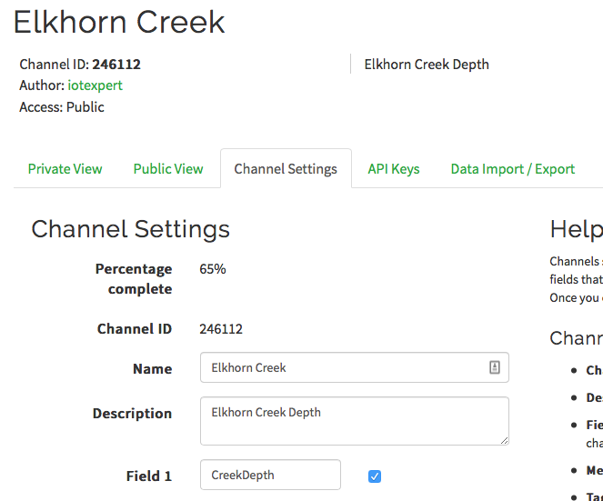
I started with a WebHook to the ThingSpeak Cloud (because they show a nice example in the documentation). ThingSpeak is run by the MathWorks people (same as Matlab). They call ThingSpeak “an open IoT with Matlab Analytics”. OK sounds cool. In order to use it to collect and display data I start by creating a new account. Then I click on the “New Channel” button to create an “Elkhorn Creek Depth” channel. On this screen I say that there will be only one field “CreekDepth”.
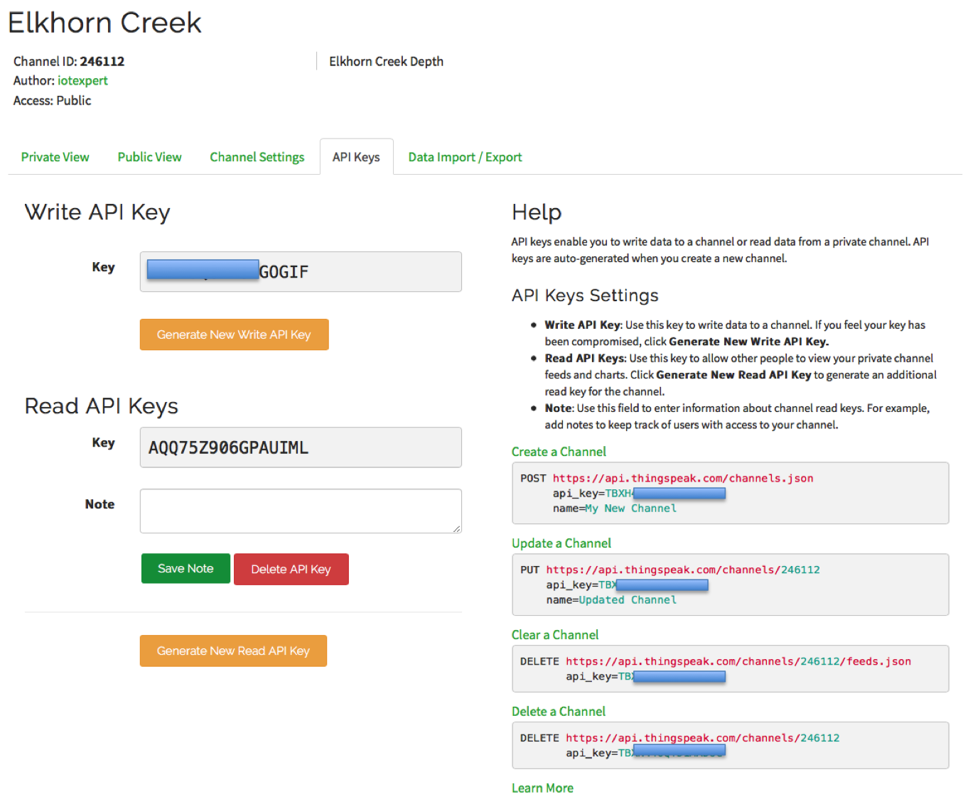
In order to write data into this channel you need to have the API keys which give your Restful API call the authority to write into the database. Press “API Keys” and you will see this screen.
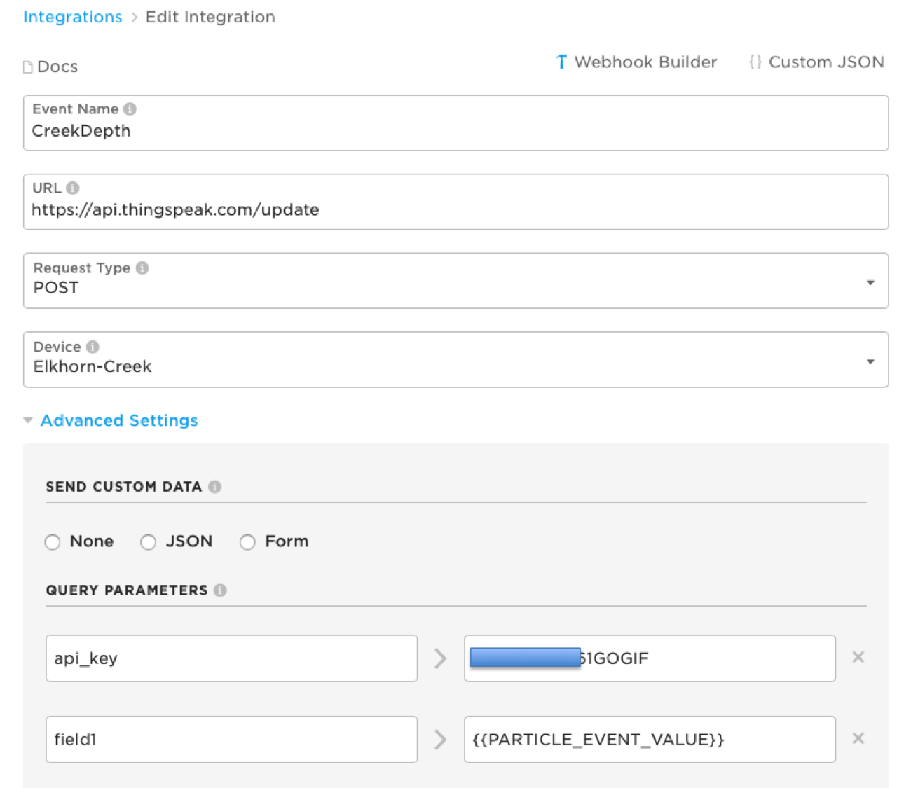
Now that I have an active channel (and I know the channel number and API write key) I go back to the Particle Cloud Integrations tab and create a Webhook.
Each time the “CreekDepth” event occurs, the Particle Cloud will do an API call to the ThingSpeak cloud and insert the new data. On the ThingSpeak Cloud there is a chart of the data, and a handy-dandy way to insert the chart into your webpage. Here it is for the Elkhorn Creek showing the last 6 hours of data which is flat at the time of this writing, but maybe when you read this page it will be raining in Kentucky and you will see something interesting.
I guess at this point I have a number of questions which I will leave to the future:
Exactly what is the form of the request made to the ThingSpeak cloud?
What is the mapping between the event –> API Request
What is the protocol for Particle.variables?
How does the Microsoft integration work?
How does the Google integration work?
How do I save power on the Photon?
I suppose Ill leave these questions to future posts. If you have other questions leave them as I comment and Ill take a crack at trying to figure them out.
I have been building up pieces of code that are going to allow me to show the PSoC Analog CoProcessor –> WICED WiFi –> Amazon IoT –> WICED WiFi –> Secret New Chip –> Robot Arm. In the previous two articles (part1, part2) I have shown you how to build most of the WICED firmware. In this article I am going to focus on the PSoC Analog CoProcessor firmware (but if you look real close you can see the secret new chip’s development kit).
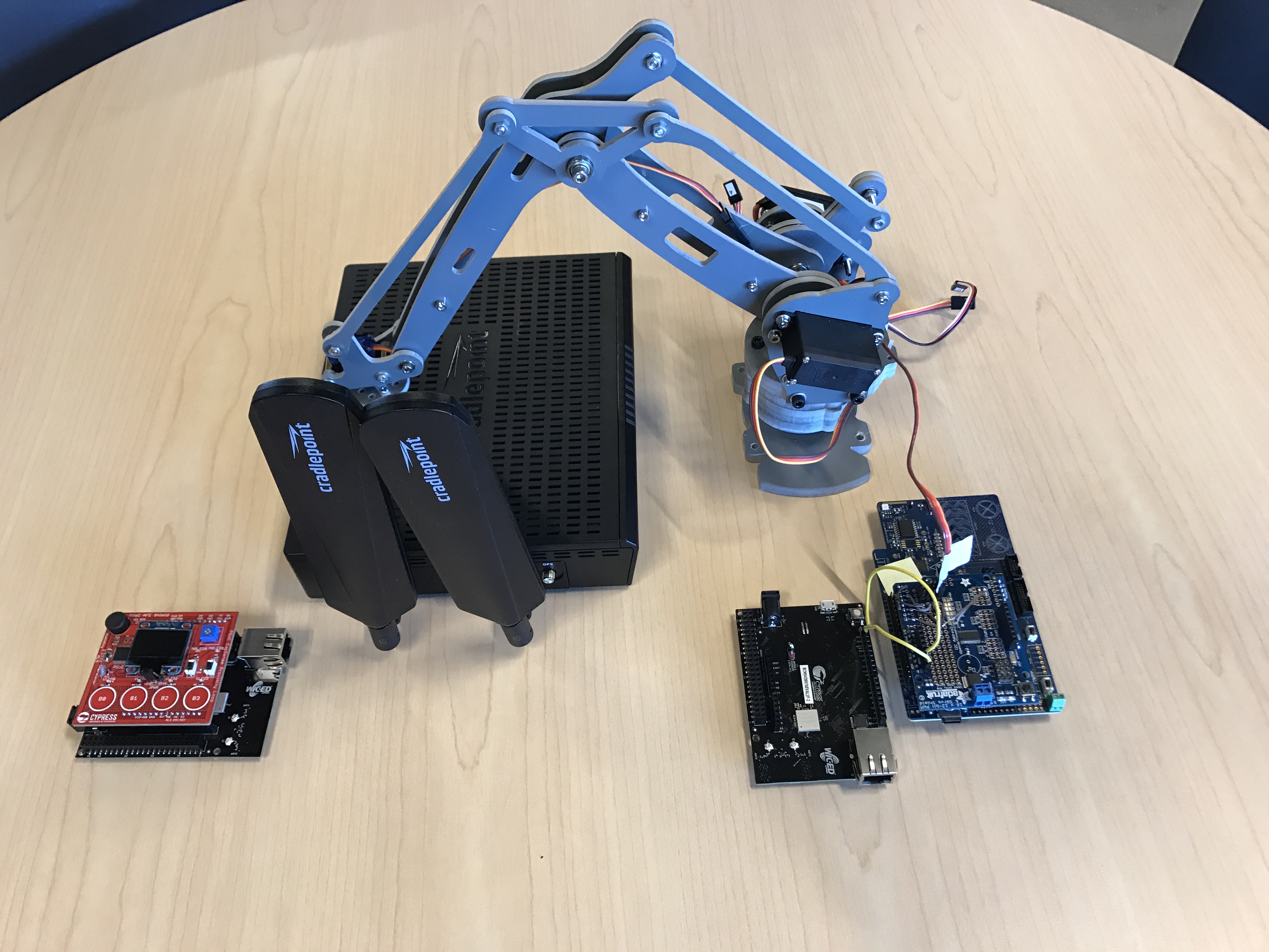
In the picture below you can see the red shield board. This is a shield with the PSoC Analog CoProcessor plus a bunch of sensors that show the power of that chip. The shield also includes 4x CapSense Buttons which I am going to use to set the position of the Robot Arm. The PSoC will serve as a front end companion to the WICED WiFi Development Kit. They will communicate via I2C with the PSoC acting as an I2C Slave and the WICED WiFi as a master. Here is a picture of the all of parts minus Amazon.com’s cloud.
PSoC Analog CoProcessor
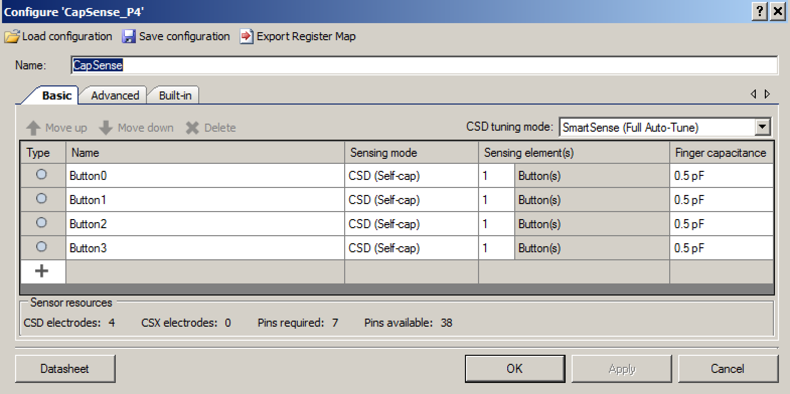
The PSoC Analog CoProcessor has the new Cypress CapSense block that gives you a bunch of new features, including enough measurement range to measure a capacitative humidity sensor (which you can see in the upper left hand part of the board). For this demonstration I am just going to use the 4 CapSense buttons. They will serve as the user interface for the Robot Arm. The 4 buttons will set 4 different positions, 20%,40%,60%,80%. I will be talking in much more detail about this shield in coming posts (later next month)
PSoC Analog CoProcessor Schematic
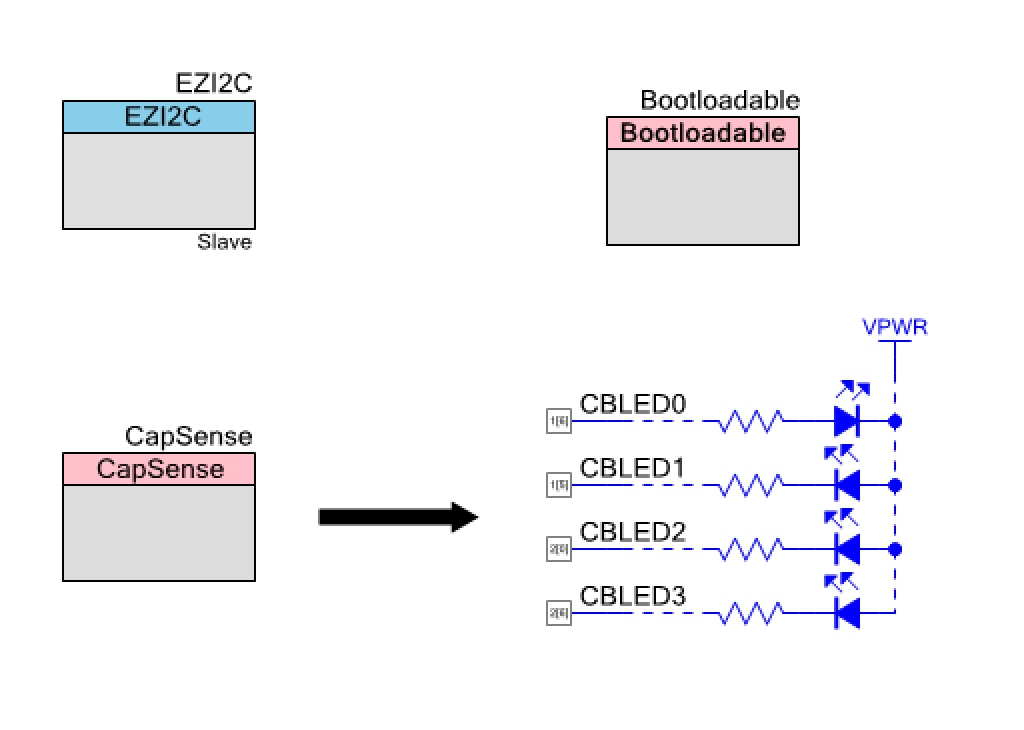
The PSoC Creator schematic is pretty straight forward. I use the EZI2C slave to provide communication for the WICED board. There are 4x LEDs that sit right next to the CapSense buttons, and there are the 4x CapSense buttons. The only slightly odd duck is the Bootloadable component which I use because when I designed the shield I did not put a programmer on it. The BootLoadable allows me to me to load new firmware into the PSoC via the I2C interface. Here is the PSoC Creator Schematic:
The CapSense configuration just specifies the use of 4x CapSense buttons that are automatically tuned by the Cypress magic.
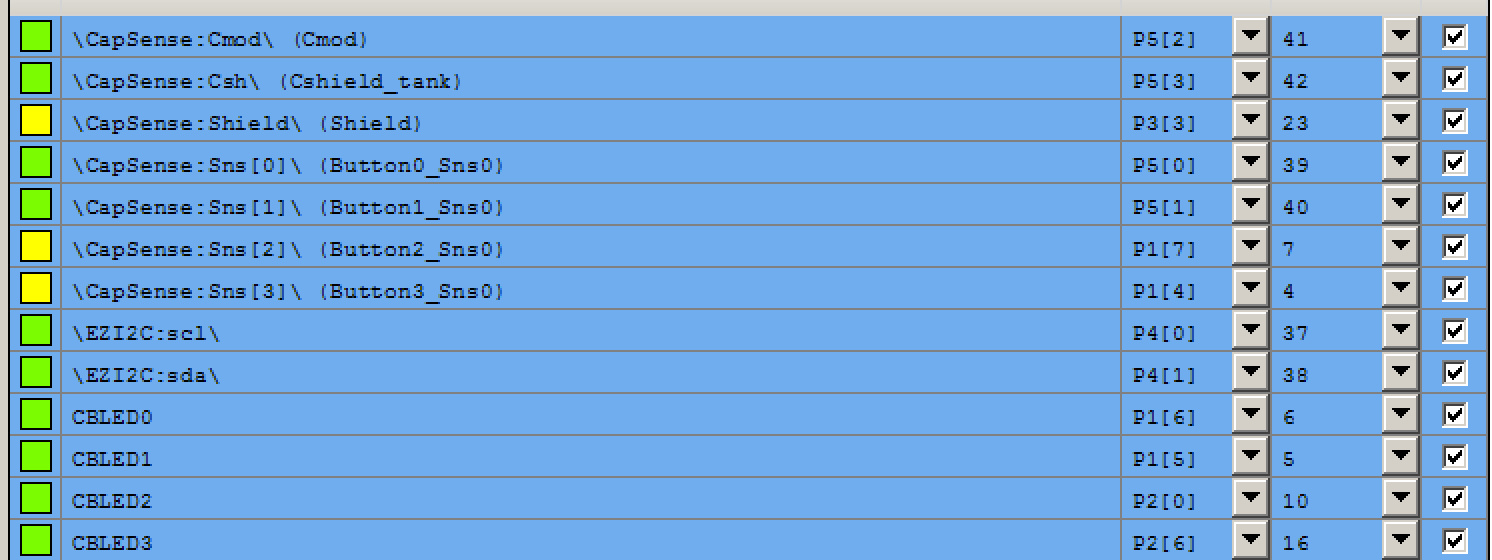
The last step in configuring the schematic is to assign all of the pins to the correct locations.
PSoC Analog CoProcessor Firmware
One of the great things about all of this process is how easy the firmware is to write.
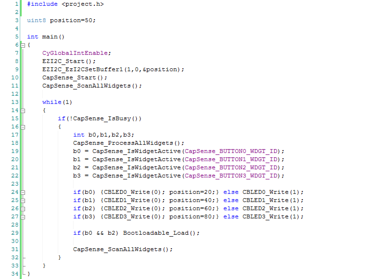
Line 3 declares a buffer that will be used to relay the position information to the WICED board. I start the position at 50%
Lines 8-9 start the EZI2C which starts up the EZI2C protocol and tells it to read from the “position” variable
Lines 10-11 gets the CapSense going
Inside of the infinite while(1) loop, I read from the CapSense and do the right thing
Lines 17-22 reads the CapSense status
Lines 24-27 set the correct position based on which buttons are pressed (notice that if no button is pressed then the position stays the same)
Line 29 turns on the Bootloader if B0 & B3 are pressed
Testing the PSoC Analog CoProcessor System
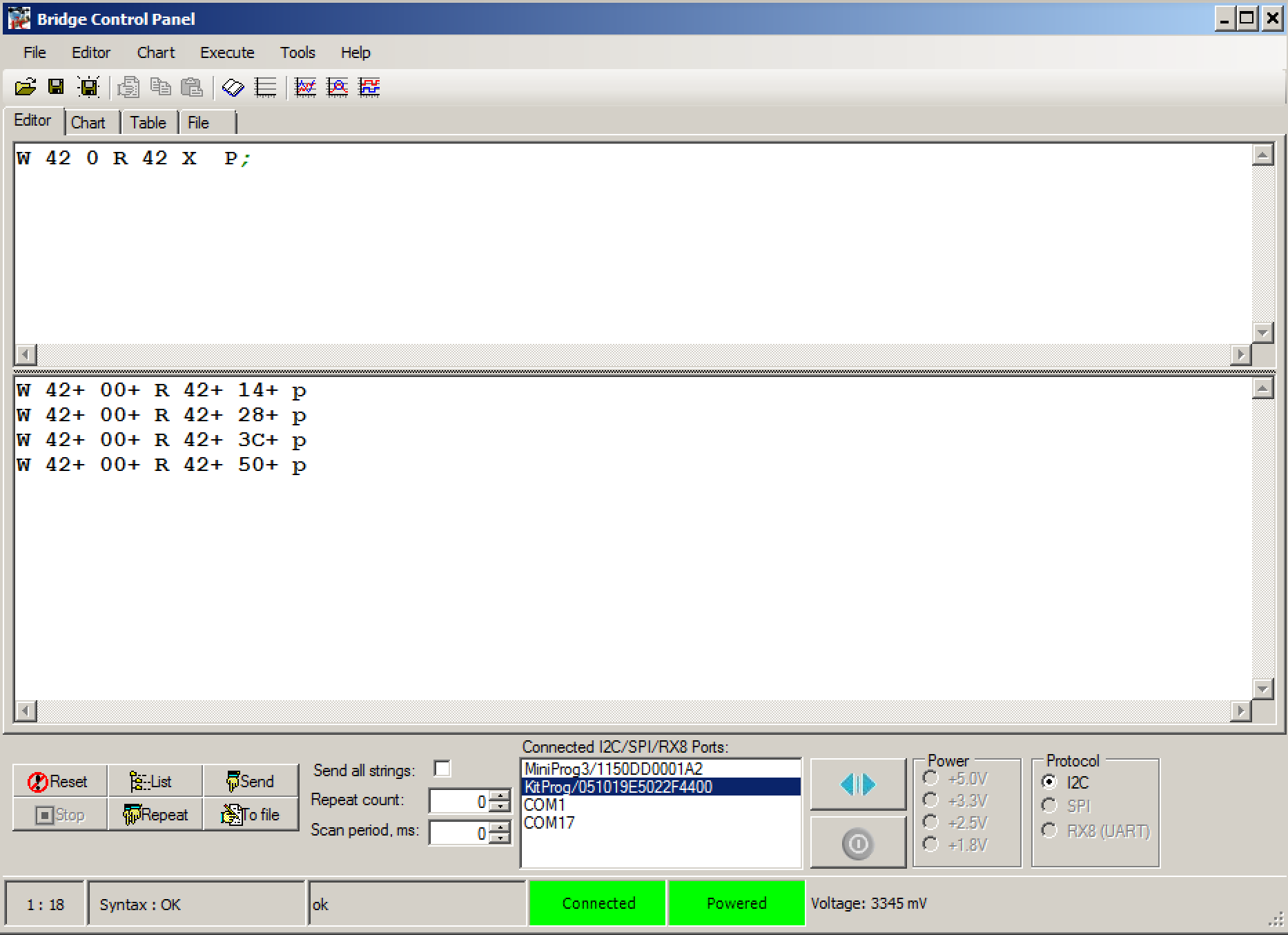
The easiest way to test the system is to use the Bridge Control Panel which comes as part of the PSoC Creator installation. It lets me read the value from the EZ2IC buffer to make sure that the CapSense buttons are doing the right thing. The command language is pretty simple. You can see in the editor window that I typed “W42 0 R 42 X p;” Everytime I press “enter” it sends the I2C commands:
Send an I2C start
write the 7-bit I2C address 0x42
write a 0
send a restart
read from address 0x42
read one byte
send a stop
You can see that I pressed each button and indeed got 20,40,60,80 (assuming you can convert hex to decimal… but trust me)
In the next article I will modify the WICED Publisher to poll the PSoC Analog CoProcessor and then publish the current state.
I am an IoT Expert using Z-Wave to build devices like wireless motion sensors, Z-Wave interfaces for the Raspberry Pi, in-wall light switch dimmers, Z-Wave water valves and a variety of other “Things”. My current job is as a consultant providing mostly firmware that runs on the Z-Wave chips from Sigma Designs. Express Controls is my company we just recently moved into real office space as we’ve outgrown my home office. I have my own Blog at DrZWave.wordpress.com where I’ll discuss Z-Wave specific things but I’ll be an occasional contributor here on Alan’s blog with more embedded and PSoC specific topics.
History
I went to RPI in the early 1980s where I honed my skills soldering and writing software. My first two jobs were designing graphics workstations and some of very first (and very primitive) GPUs of the day. I went on to designing chips for video conferencing compression engines, the cockpit display of the F22 fighter, Wireless Ethernet (before it was a standard) and a variety of chips for big and mostly small companies. Most of the chip designs were done as a contractor while I was also starting my first company, VAutomation which made “cores” for 8 and 16-bit CPU as well as USB and Ethernet interfaces. I sold VAutomation in 2001 and started playing with Z-Wave in 2003. I am the 31st Z-Wave licensee (there are now several hundred). At that time I went to work for a camera chip company that Cypress Semiconductor purchased and then I moved into working for Cypress which is where I met Alan. I worked on many chips at Cypress and specifically on the PSoC5 family. I moved on to do my own thing in 2014 and have been building Z-Wave IoT devices since before the Internet of Things (IoT) was a “thing”. PSoCs are just so easy to use that I use them for my own products and recommend them to my clients.
If you have any Z-Wave questions – just contact DrZwave and I’ll try to respond in a timely fashion.
Volunteer
I am also a Solar Power enthusiast and renewable energy advocate. My 30 solar PV panels generate over 1MWhr each month of clean solar power which covers my electric bill. I volunteer with HAREI which is a group that helps people put solar power on their roof with paybacks in as little as 2 years.
Last week I had the supreme privilege of hosting the WICED WiFI + Bluetooth + Zigbee software team at my office in Kentucky. This included the overall manager for WICED software (a truly remarkable guy), the engineering managers for WiFI and Bluetooth, the head of applications for WICED as well as a bunch of the firmware guys. It occurred to me during the week that the people joining Cypress was the best part of the Broadcomm IOT acquisition. And that is saying something as I really like the products. Also at the summit were all of the software engineering leaders for PSoC (who I have worked with closely all of my career). Needless to say, it was a bunch of badass developers.
The purpose of the meeting was to introduce the PSoC team to WICED and then talk about the future roadmap for those products. Obviously I can’t talk to much about the 2nd part… well actually the only thing I can say is that it will be amazing as we will be able to offer PSoC with the power of WICED.
What I can talk about is the first part. So, I thought that I would show you one of the things that we did with WICED. First of all, WICED (Wireless Internet Connectivity for Embedded Devices) is the brand name that Cypress uses to describe all of the WiFi, Zigbee and Bluetooth chips and modules that were acquired from Broadcom/Avago. The other thing we call WICED is the WICED SDK which is used to mean Eclipse plus all of the tools (programer, plugins etc) plus the software library that is used to build products using the WICED chips and modules.
In the world of programming the first example is always “hello world”. In the world of MCUs the first example is always “blinking led”. It turns out that the first example in WiFi is “scan” to show that you can see all of the WiFi networks around you. The purpose of all of these examples is to prove that all of the tools can do their thing.
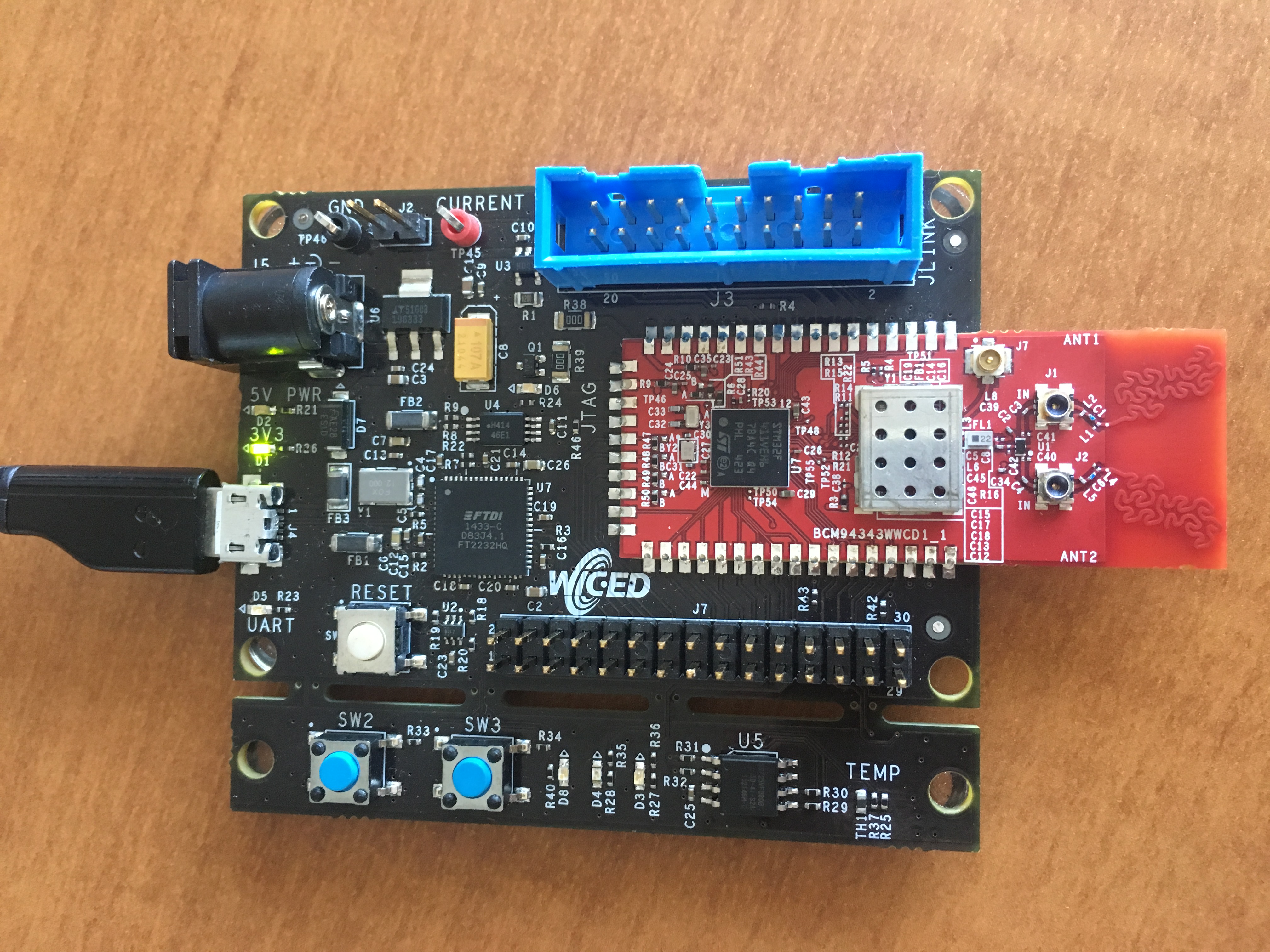
To start with they gave me this devkit, the BCM94343WWCD1_1
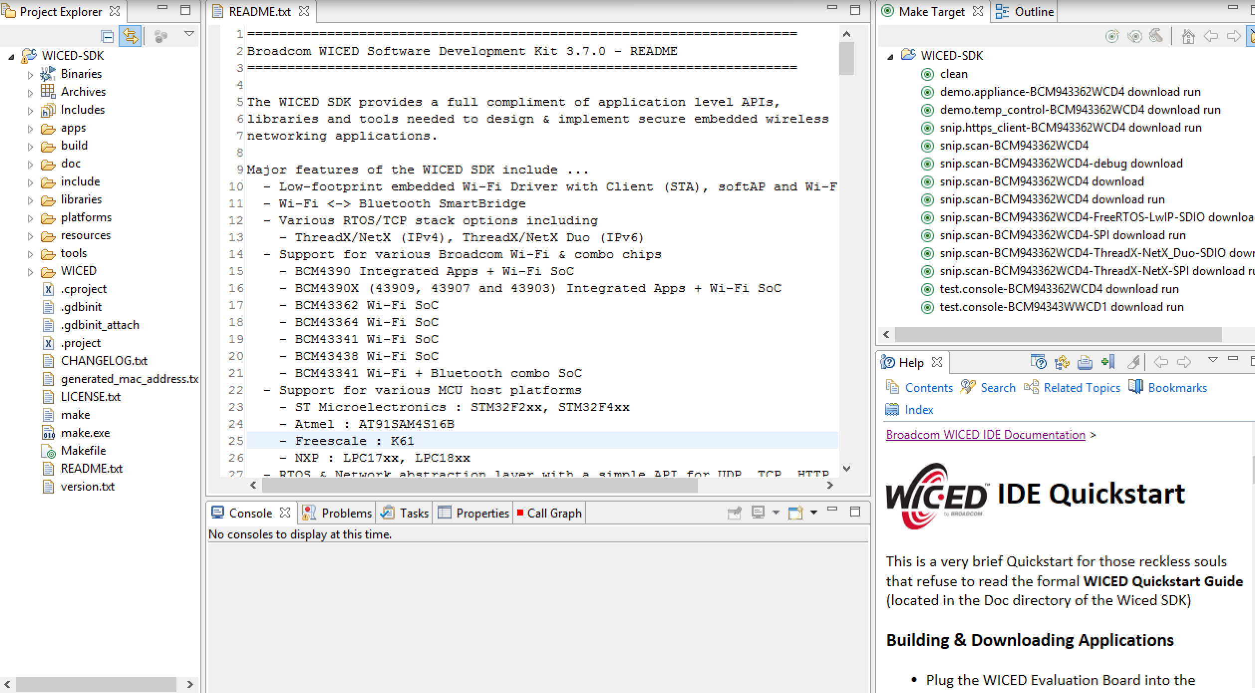
The first thing to do is install WICED 3.7. When you start WICED you will see a screen like this:
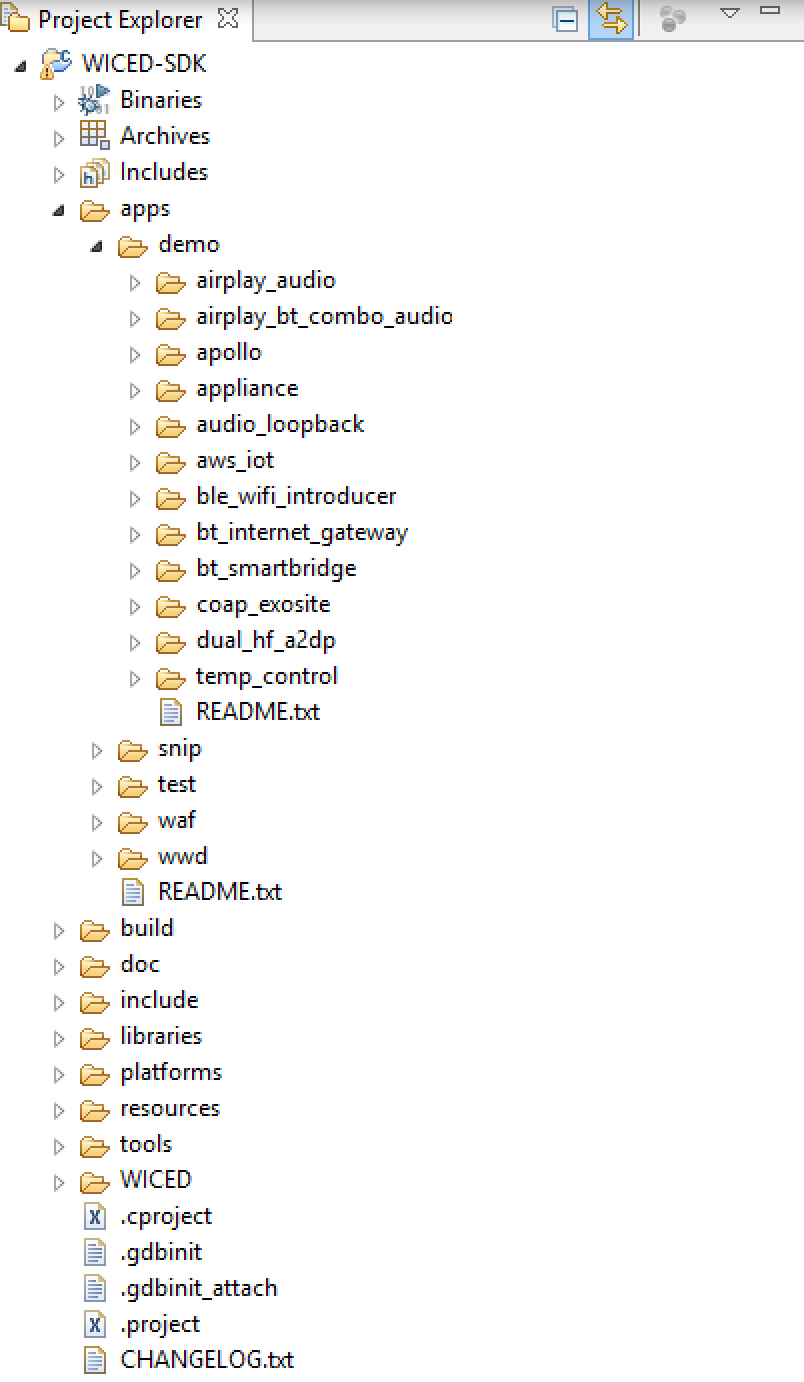
For the purposes of the first design there are two important things to see on this screen. First on the left side is the project explorer. It has all of the guts of WICED. As part of the installation we provide you a bunch of “apps”. These apps range from simple examples (in the snip folder) to full fledged production quality applications (in the demo folder)
demo – full fledged applications
snip – short example projects
test – tools for debugging and testing wifi
waf – WICED Application Framework support (like an OTA Bootloader)
wwd – low level driver examples
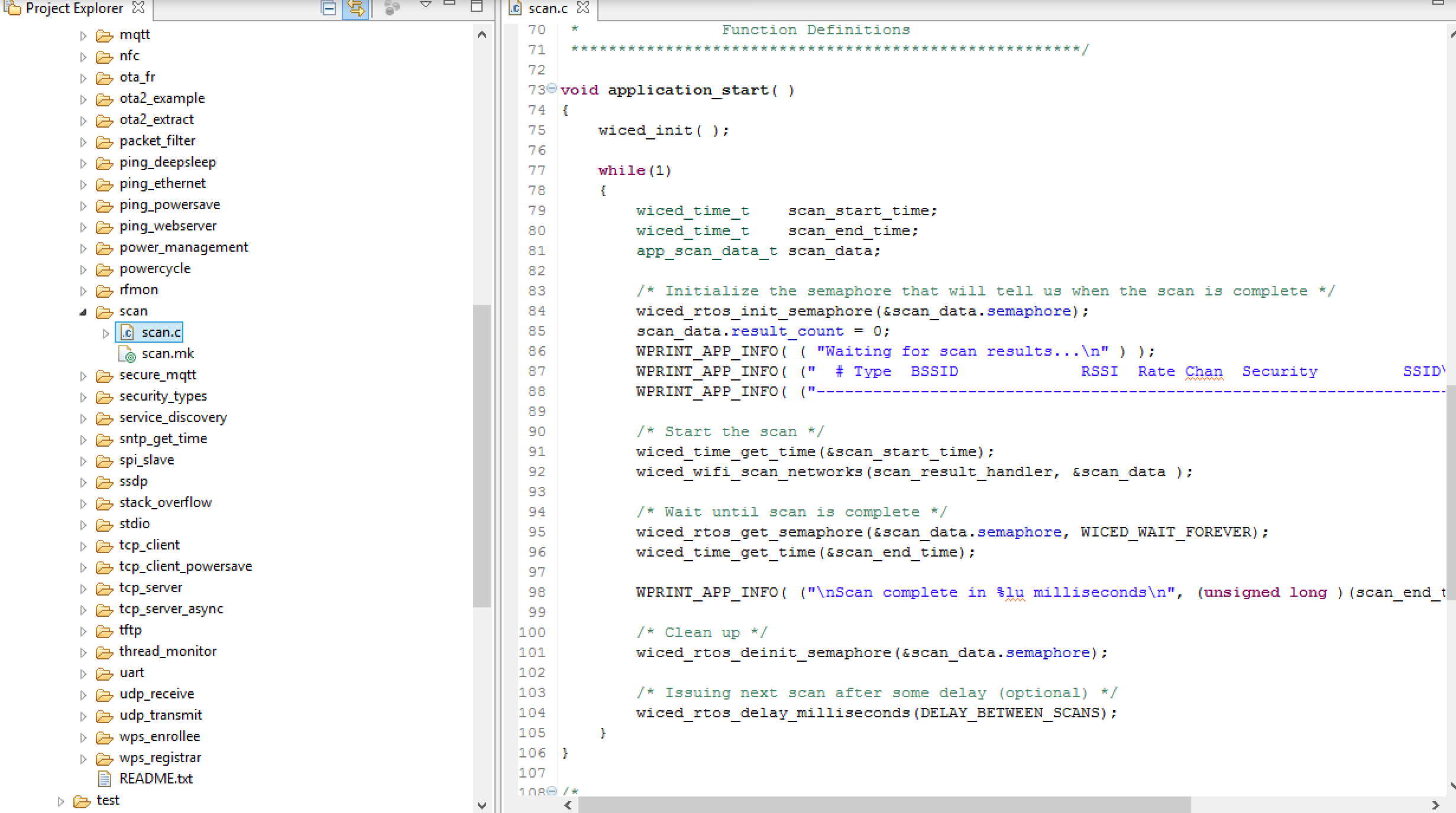
The example that I want to build is “scan” specifically “scan.c”. That can be found in the apps/snip/scan folder. In this screenshot you can see that I opened “scan.c”
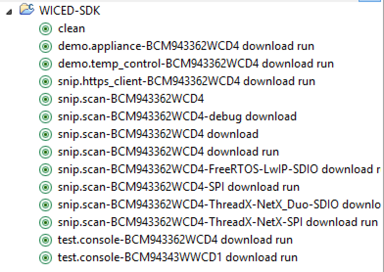
The next thing that you need to do is build a “make target”. The WICED team built a makefile that can seemingly do everything. The makefile uses the name of the make target to setup all of the options required to do the make. If you look on the right side of the screen you can see the currently existing targets:
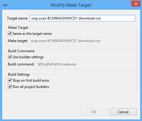
The easiest way to make a new target is to copy/paste a currently existing target. Then you can right click on the new target and edit it to get things setup correctly. The target name defines:
snip – the directory
scan – the subdirectory will the files (scan.c and scan.mk)
BCM94343WWCD1 – the name of the devkit (you can see it on the picture of the devkit)
download run – instructions to go ahead a boatload and start the app running
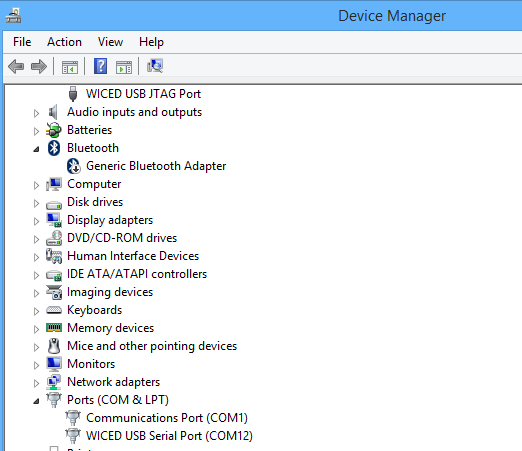
Next, I plug in the devkit. When it attachs, the devkit will enumerate as two USB devices
WICED USB JTAG Port
A serial port (in this case on COM12)
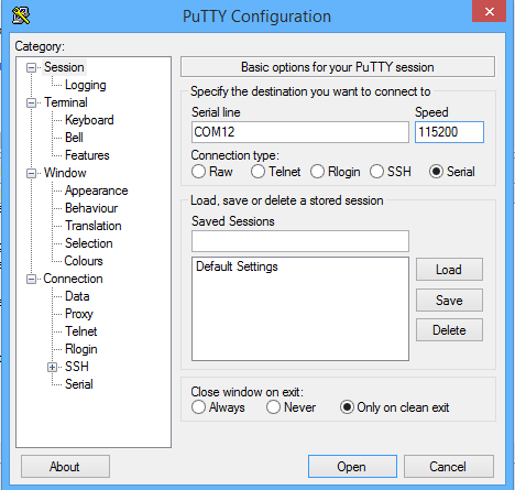
After I plug in the kit I run Putty and attach to COM12 at 115200 baud
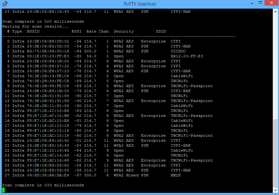
And finally, double click the make target to build, download and run. After it starts, the Putty screen fills up with all of the WiFI networks that are around me.
All of that was pretty easy to get going. Next lets see if I can actually do something. Last week I showed the guys the Elkhorn Creek Water Level monitoring project and I told them that by the end of this week I would put one of their devkits into that system, so the next several posts will be about that process. (I hope)
In my job I spend a lot of time teaching people how to use Cypress Products. One of the best students that I ever had was Paul Bentley the Cypress VP of Sales for Europe. He came to Kentucky a few years ago to take my class. He dove in with reckless abandon and did a amazing job learning how to actually program the PSoC (not just talk about it on powerpoint). Recently, he was anointed with the responsibility to teach more of our Sales team to use PSoC at the Sales Technical Conference (STCON) which is going on this week.
For some time I have wanted a very simple, inexpensive board to help teach people how get going using our chips…. all of our chips both the FM products as well as the PSoC products. The STCON afforded the perfect opportunity to build an education board. I am very lucky to work with some really good people (in India and New Hampshire) who did the work of realizing the vision of a simple board and getting it made in short time.
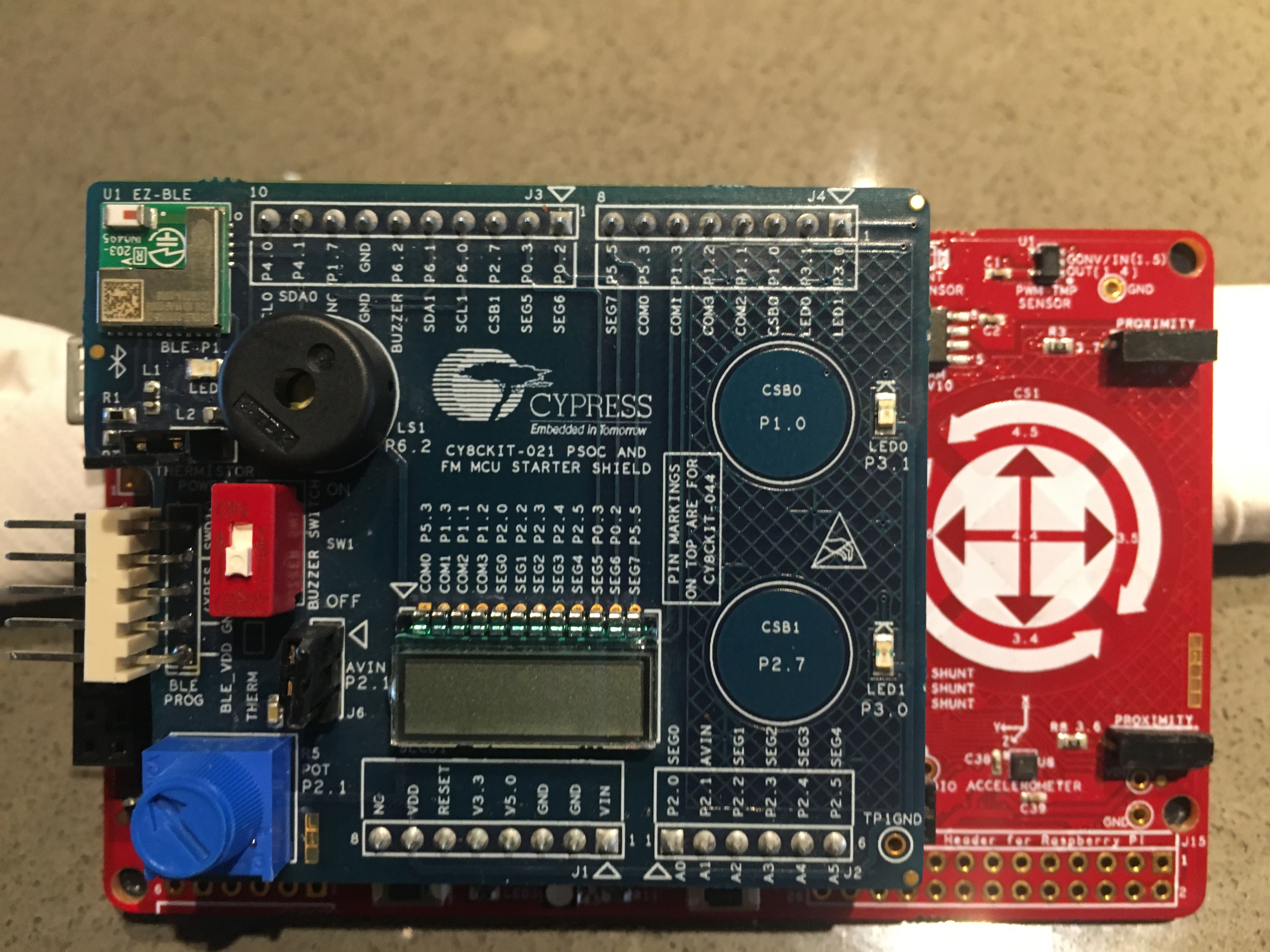
Without further ado, here it is, the provisionally name CY8CKIT-021 PSoC and FM Starter Shield (shown connected to the CY8CKIT-044).
The shield has an Arduino compatible footprint and has:
2 CapSense Buttons
A Potentiometer
A Thermistor
2 LEDs
A PRoC BLE Module
A Piezo-electric buzzer
A 7 Segment direct drive LCD
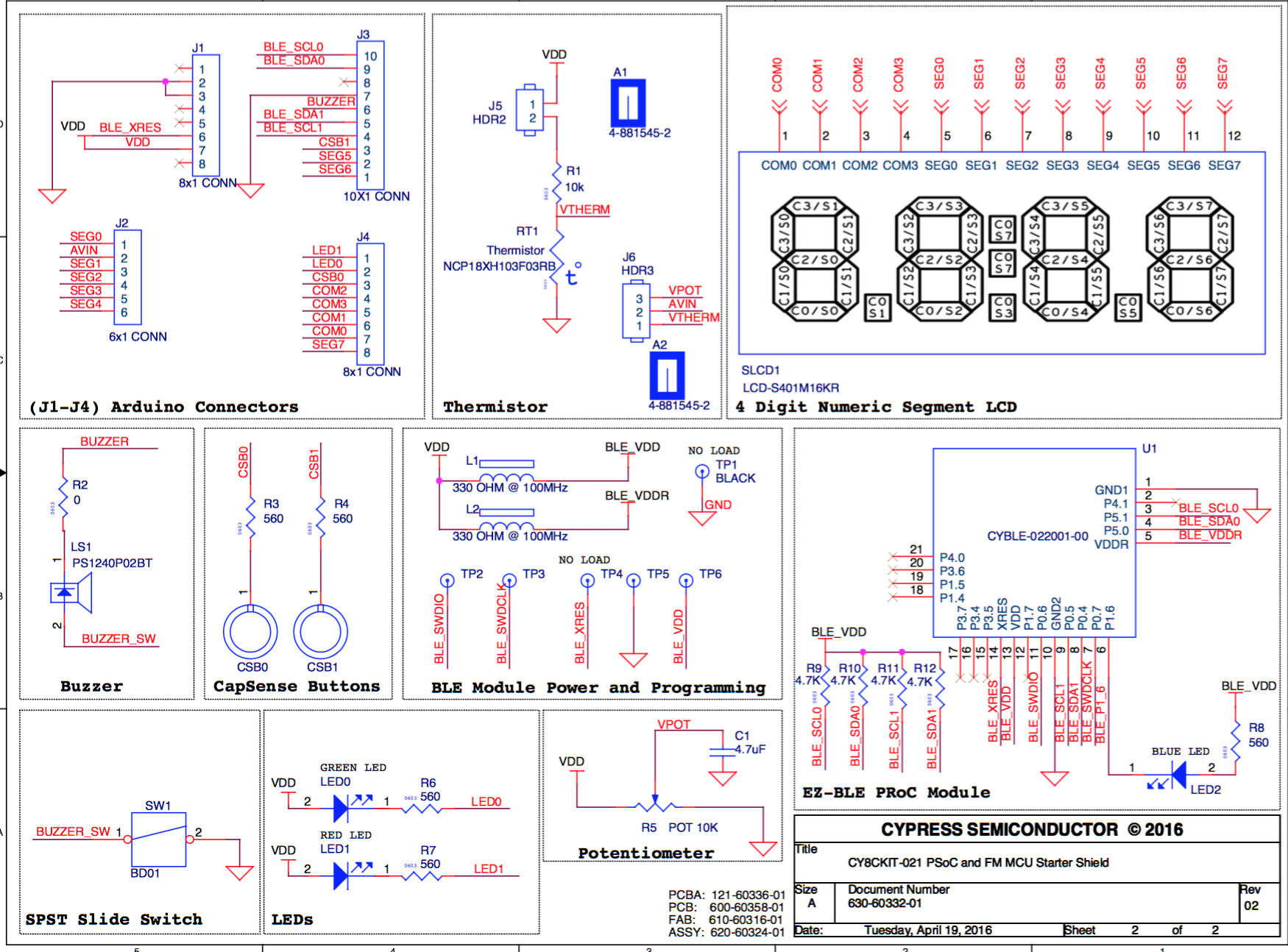
The PRoC is connected to the USB-I2C bridge on the programmer as well as the serial (I2C/UART) pins on the base board. Here is the schematic:
One of the cool things about this board is that it is generally compatible with a bunch of the Cypress products including:
CY8CKIT-042
CY8CKIT-042-BLE
CY8CKIT-044 (which is shown in the picture above)
CY8CKIT-046
S6E1B8
S6E1C3
Over the next several days I am going to show you example projects using the board. I will culminate at the end of the week by IOTifying the board by writing BLE firmware for the PRoC, building an IOS app and an Android app to talk to the board.
In this post, I will take you through the PRoC BLE schematic and firmware. I describe a very similar version to this in great detail in the video you can find on the Cypress Video Training website.
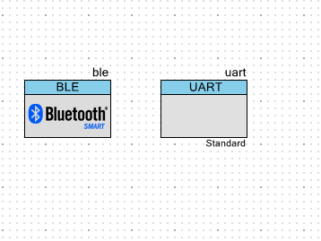
First, I create a new project in my workspace called “145capsenseled-ble.” Then, I add the UART component (the SCB version) and the BLE component.
Next, I configure the component to be a GATT server with a custom profile and a GAP client.
Then I create a custom service with two characteristics:
The “led” characteristic, which is set up as a uint8 that is writeable and readable.
The “capsense” characteristic, which is set up as uint16 that is readable and has a “notify.”
Next, I configure the UUIDs of the service and characteristics to match what is hard-coded in the iOS app. Then, I add “Client User Descriptions” that describe the characteristics in plain text.
Next I configure the GAP settings, specifically the advertising packet.
I make the pin I assignments, which is just the UART Rx and Tx lines.
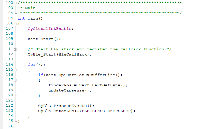
Finally, I write the firmware. I started with main. In the infinite loop (line 116), if I have received a byte from other side, then I assign it to the global variable “fingerPos” (line 118). Next, call updateCapsense() (line 119), to update the GATT database with the new value of the slider.
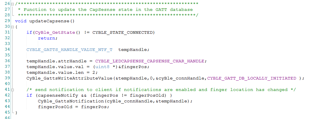
The updateCapsense function:
Lines 31/32 If there is no connection, then don’t update the GATT database.
Lines 33-39 Update the GATT database with the current fingerPosition.
Lines 42-43 If the iPhone side has asked for notification and the position has changed, then send a notification.
Line 44 Save the last position.
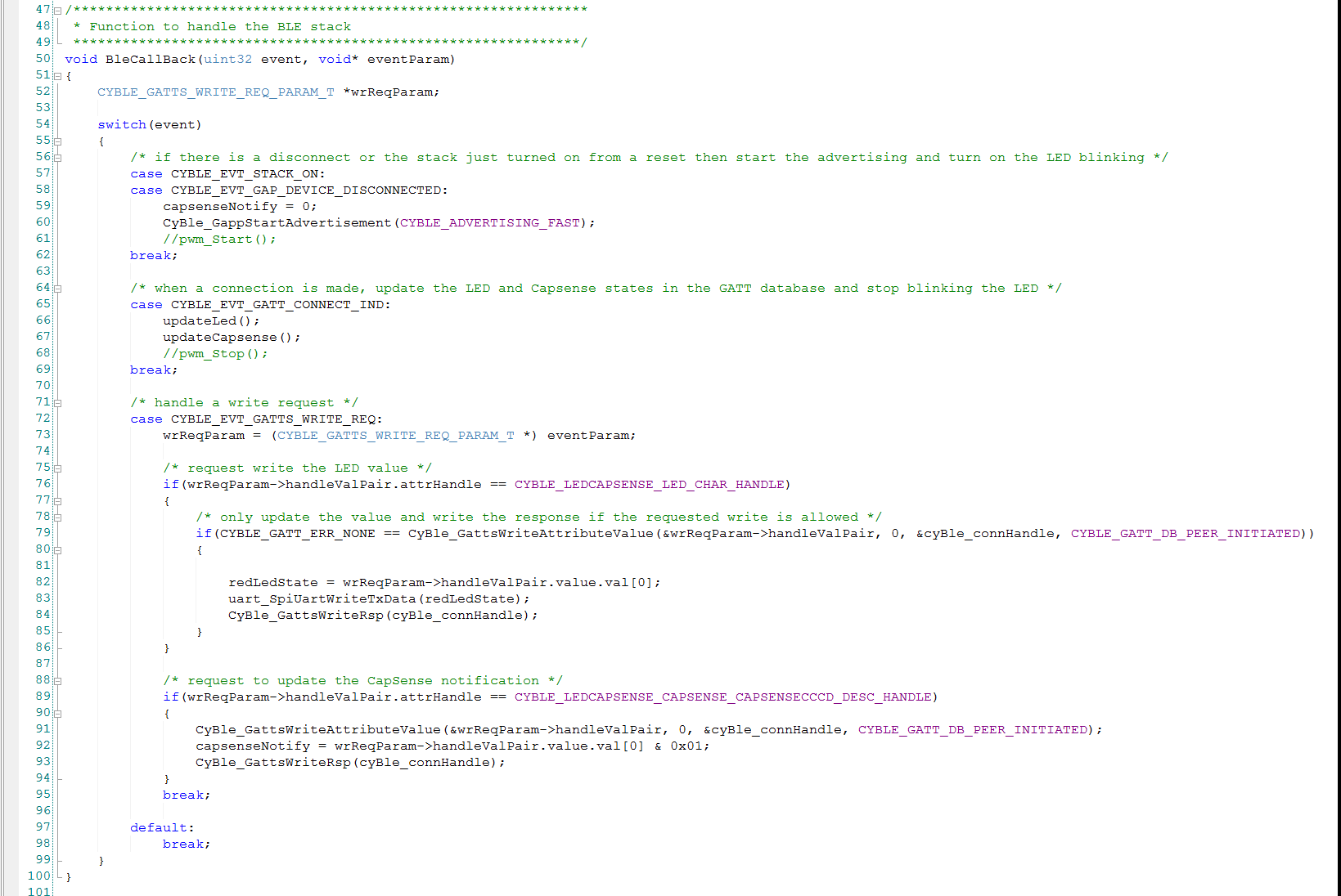
The BleCallBack is the most complicated section of firmware. It uses a “switch” statement to handle the different event “cases.” The cases are:
CYBLE_EVT_STACK_ON & CYBLE_EVT_GAP_DEVICE_DISCONNECTED: In either of these cases you want to start the advertising function.
CYBLE_EVT_GATT_CONNECT_IND: When there is a connection made, update the GATT database with the current state of the CapSense and the LED. This allows the iOS side to read the correct values.
CYBLE_EVT_WRITE_REQ: There are two kinds of write requests that are valid.
CYBLE_LED_CAPSENSE_LED_CHAR_HANDLE: If the remote side writes into the LED value, then send that data to the PSoC4000S via the UART.
CYBLE_LEDCAPSENSE_CAPSENSE_CAPSENSECCCD: If the remote side has been asked to notify (or un-notify), then save that in the global variable capsenseNotify.
That is all of the firmware.
In the next post, I’ll take you through the debugging I had to do.
You can find the PSoC Creator workspace on github in the directory called “capsenseble-145.”
One of the cool things about my job is I get to try out lots of new development kits before they are released to the general public. In the previous post I talked about the demonstration I gave at the Embedded World conference using the CY8CKIT-042 BLE. You can find a complete video tutorial for that project on the cypress.com video tutorial website. While I was at the conference, I picked up an engineering sample of a new development kit and put it into my backpack because I wanted to try a new feature of PSoC Creator on the way home. But, when I got on the airplane, I thought I would build the same project I had demonstrated at the conference using this kit. So, in the next few posts, I am going to show you the new CY8CKIT145 Stamp Board and how to build an IOT solution with it.
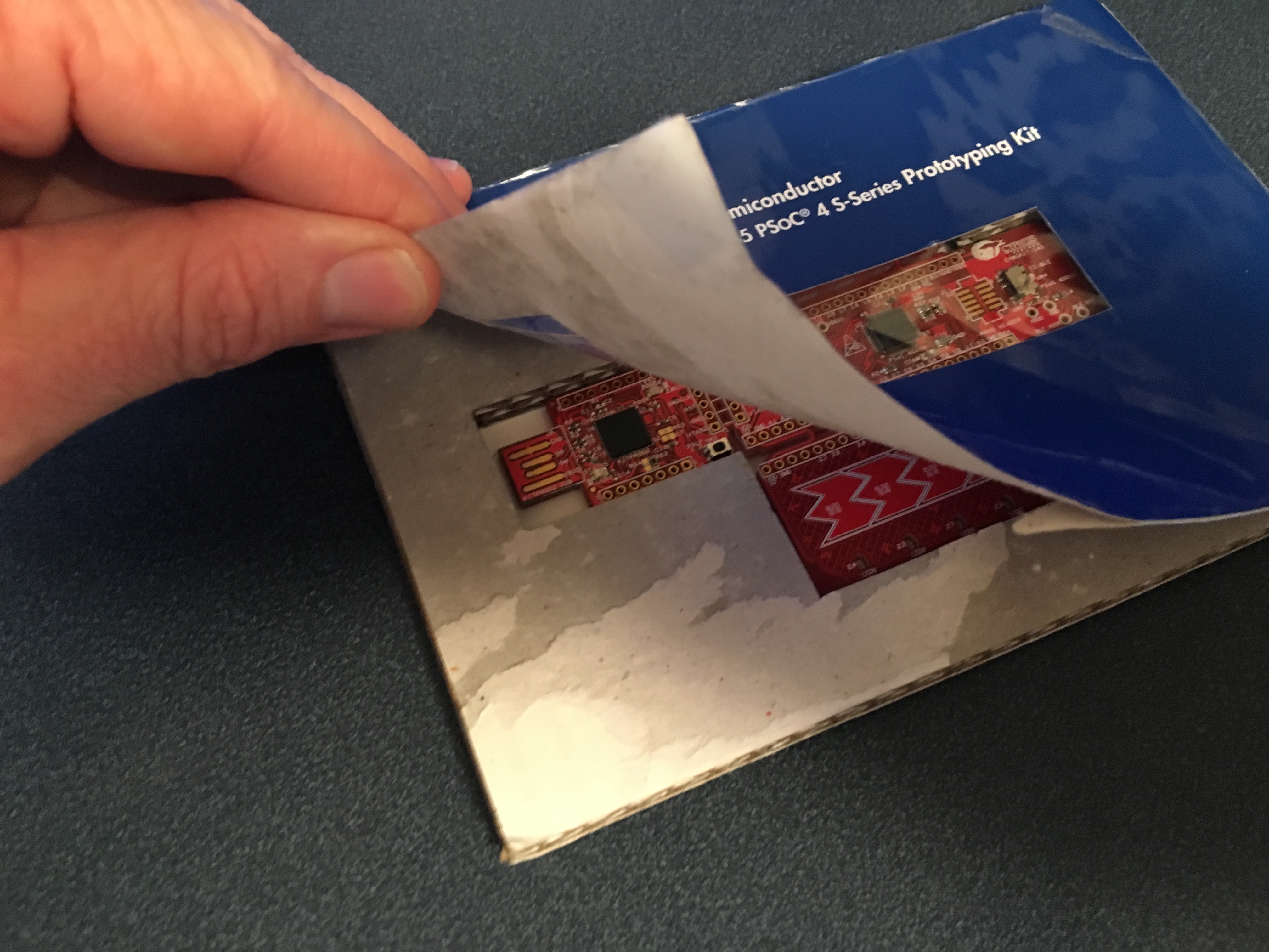
It is called a “stamp board” because it comes in a flat postage stamp-like postcard mailer. Here is a picture of the front and the back (you can see that it has already lived a hard life riding around in my backpack).
Here is the back of the mailer:
In the picture you can see the yellow label proclaiming this to be an engineering sample. It doesn’t seem like much, but when you pull back the front of the package you get to see the surprise:
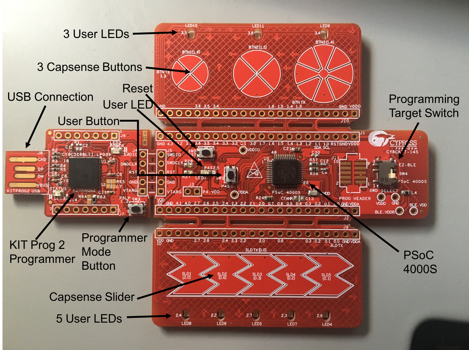
The kit can literally be broken into four separate pieces:
A programming selector (to pick either the PSoC4000s or the PRoC BLE (that is on the back of the kit)) as the target of the programmer
All of the PSoC4000S pins are available on the 100mil center headers
A PCB footprint for a 10-pin ARM programming header
A programmer board:
A PSoC5LP programmed with KitProg2 Firmware
A programmer mode button
100mil center header with some of the PSoC5LP pins
A Capsense slider user interface board with a 5 Segment Slider and 5 LEDs
A Capsense button user interface board with 3 mutual capacitance buttons and 3 LEDs
And the back, with the tiny 10mm X 10mm PRoC BLE module:
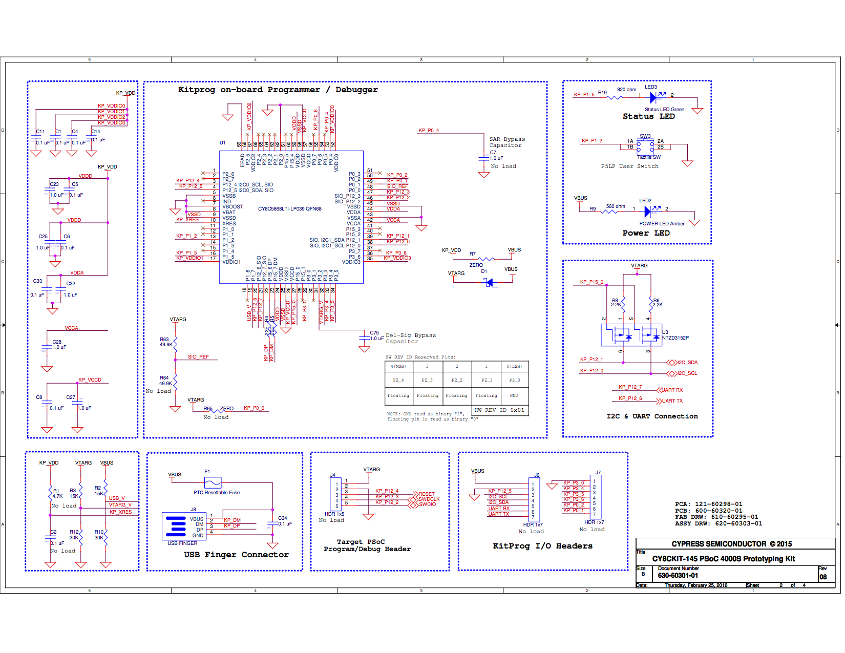
Here is the schematic for the board:
I wanted to build a project that would have two-way communication between my iPhone and the board, and would be compatible with the Swift App I had written. The user of the board would have a capsense slider (and LEDs) of which the iPhone App could read the position. In addition, it would have an LED that the iOS app could turn on and off. Here is a demonstration that I filmed with my iPhone on the airplane:
In the next post I will describe the overall system and show you the firmware.
My friend Bill Cloyd runs a non-profit company in Lexington, Kentucky called Newtons Attic. The company focuses on Engineering and Physics education for kids. Billy runs day camps, week camps and after school camps for primary school kids. In these camps/classes the kids build robots, catapults, cross-bows, Rube Goldberg machines, fly drones etc. uising the tools in the machine shop at the Newtons Attic Campus. This is the perfect place for budding engineers and scientists. In addition to this he does road shows with his crazy machines.
One of the machines (called G-Force) is 120′ long track with a spring activated car. One end of the track curves up to the sky. This is an excellent platform for teaching kids about Newtons Laws. Here are a couple of pictures:
When high-school physics classes visit Newtons Attic they take “data” using stop watches etc and then try to match their observations to the predictions that result from Newtons Law. I always felt that this process would greatly benefit from some automation. I have launched into a project to build an electronic system that can attach to the car and collect and transmit the kinematic data from the car. For those of you who have forgotten kinematic data is position, velocity and acceleration.
To do this I am building a system around the new Cypress PSoC4-BLE chip. The system will have the following “sensors”
1. A Linear Encoder attached to a wheel running along the track
2. A 3-Axis Accelerometer
3. A 3-Axis Gyro
4. A 3-Axir Magnetometer
5. A Spansion (now Cypress) SPI Flash to record the data
6. An Air Pressure Sensor and a Relative Humidity Sensor (which I will use to calculate the Air Density)
The PSoC4-BLE will collect the data from these sensor and broadcast the data to any BLE Enabled device (iPhone, Android Phone).
The last part of the system will be a Swift App (running on iPhone) and a Java App (running on Android) to collect and display the data.
In the next bunch of posts you will be able to follow me through the Schematic Design, Board Design, Firmware Development, Board Manufacturing and App development process.
This whole home automation space is crazy. It is fractured into many many different and incompatible “standards”. I have heard (though not verified myself) that many of the Zigbee radios used for home automation are not compatible and there are cases where the central hub has multiple radios to deal with the differences in the networking stacks. Other physical standards, like WiFi, have standard physical layers (802.11) and standard network layers (TCP/IP) but lack standardization higher up in the application layer.
So, Zwave. There are literally hundreds of compatible devices. And, as best I can tell, it can handle most anything that you would want or need to do home automation. I personally think that it is really cool that I can buy Zwave devices at Lowe’s in Georgetown, Kentucky. You can also buy them at Amazon, Staples and many other online places. That is pretty awesome. Zwave also seems to be one of the least expensive radio standards; you can buy modules in low quantities from Digikey for $5. The least expensive WiFi modules are something like $15 in low volume.
But it is really annoying that Sigma tries to squash the low volume market by raping their would-be customers for development kits and software licenses.
On the hub/host side of Zwave there is OpenZwave, an open source project to provide host side control of Zwave networks. The groups seems to be pretty active and I think that I will try out some of their stuff.

 After that I can Read and Write attributes (like the LED Attribute) by typing the value I want to write into the box on the upper right, and pressing “Write Value”. For example you can turn on the LED by writing a “1” into the LED characteristic.
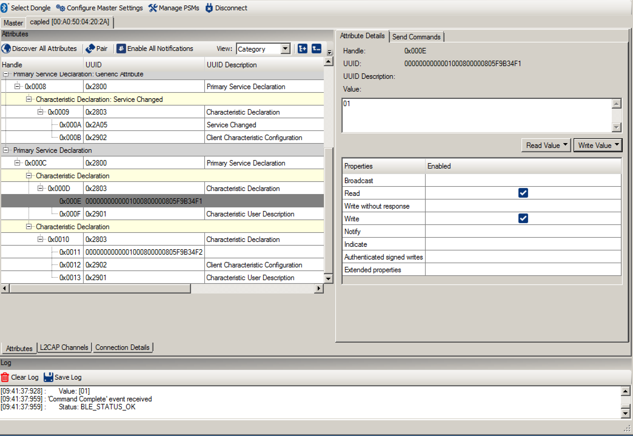


