Mouser PSoC6-WiFi-BT L6 : Integrate GoBle Bluetooth into the Game

Designing low-power, cloud-connected IoT devices with PSoC® 6 MCU’s and WICED® Wi-Fi/Bluetooth

Summary

At this point we have a working BLE Remote Control and a working Game.  In this lesson I’ll merge the two projects together so that the GoBle remote control will be able to control the game paddle.  It will do this by creating messages (just like the CapSense messages) and sending them to the Game thread via the paddleQueue.  And it will send “Button0” messages when “Button A” is pressed.

To implement this lesson I will follow these steps:

  1. Copy everything into a new project
  2. Modify the Makefile
  3. Modify main.c
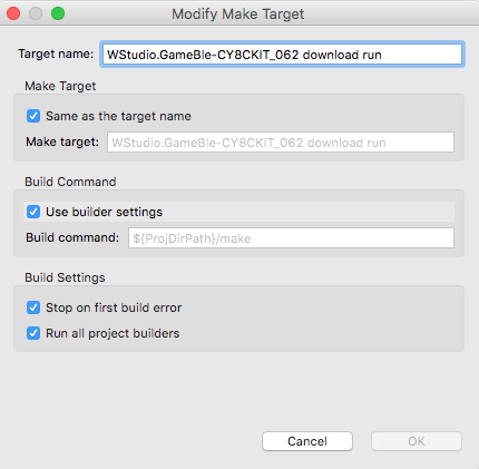
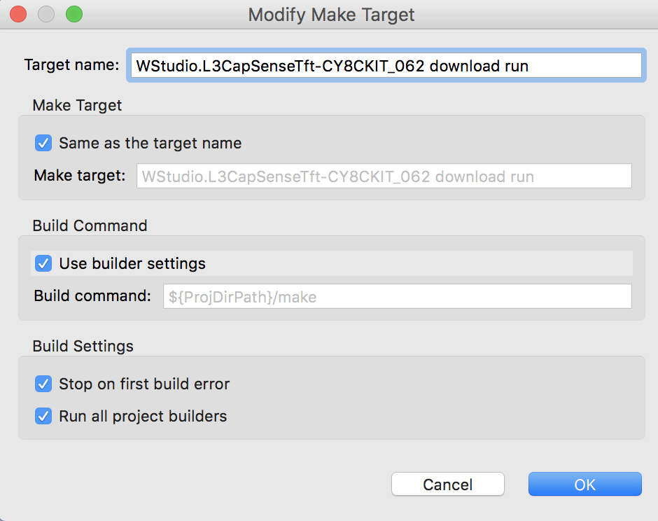
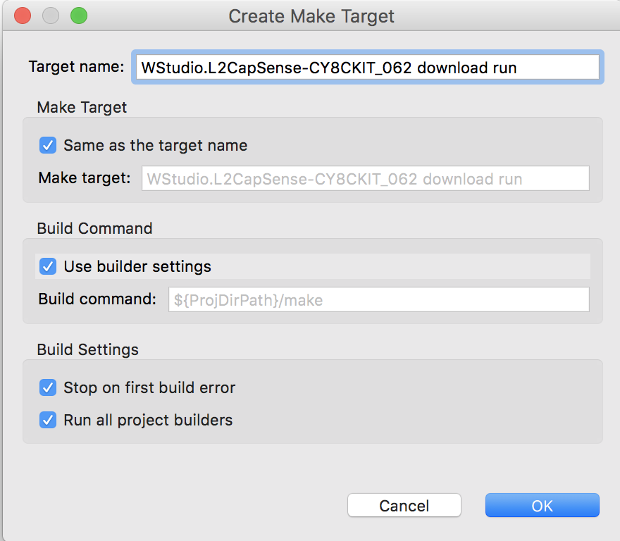
  4. Create a new make target
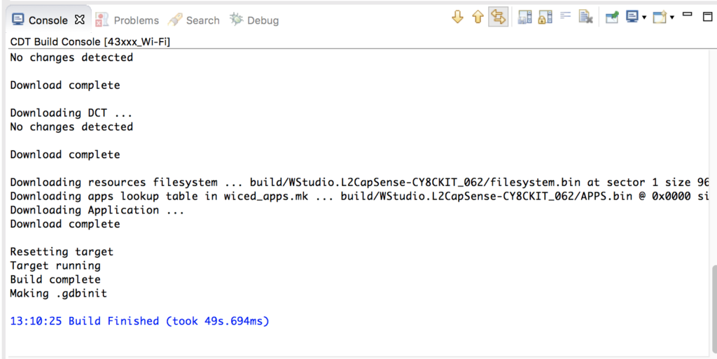
  5. Test it all to make sure things are still working
  6. Modify GoBleThread.c
  7. Program and Test

Copy L4Game into a new project L6GameBle

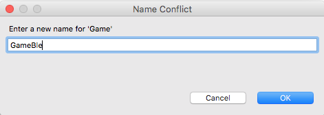
Use “copy” and “paste” to create a new project, when you paste give it the name “L6GameBle” (there is an error in the screenshot)

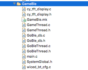
Copy the files GoBle_db.c/h, GoBleThread.c/h, and wiced_bt_cfg.c from the GoBle project into your new GameBle project.  After that is done your project should look like this:

Modify the Makefile

  1. Change the name of the App to “App_WStudio_L6GameBle”
  2. Add the new source files
  3. Add the BLE Library “libraries/drivers/bluetooth/low_energy”
NAME := App_WStudio_L6GameBle

$(NAME)_SOURCES := main.c \
    CapSenseThread.c \
	GameThread.c \
	cy_tft_display.c \
	GoBleThread.c \
	GoBle_db.c \
	wiced_bt_cfg.c

$(NAME)_COMPONENTS := graphics/ugui \
                      libraries/drivers/bluetooth/low_energy

Modify main.c

Add the include for the GeBleThread.

#include "GameThread.h"
#include "GoBleThread.h"
#include "CapSenseThread.h"
#include "wiced.h"

In the application_start function add a call GoBleThread_start() to get the GoBle thread going

void application_start( )
{
    wiced_init( );
    wiced_rtos_init_queue(&paddleQueue,"paddleQueue",sizeof(game_msg_t),10);
    wiced_rtos_create_thread(&blinkThreadHandle,7,"Blink Thread",pdlBlinkThread,500,0);
    wiced_rtos_create_thread(&capSenseThreadHandle,7,"CapSense Thread",capSenseThread,1024,0);
    wiced_rtos_create_thread(&gameThreadHandle,7,"game Thread",gameThread,4096,0);
    GoBleThread_start();
 }

Create a new make target

Test it all to make sure things are still working

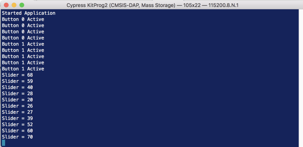
Run the make target and make sure that the game still plays and that you can get remote control messages.

Modify GoBleThread.c

Add the includes for the GameThread (to get access to the game message structure) and SystemGlobal (to get access to the queue)

#include "GameThread.h"
#include "SystemGlobal.h"

I don’t need (or want) the button/slider printout information.  So I will delete the old button code from goble_event_handler. (delete this stuff)

            WPRINT_APP_INFO(("# Buttons = %d ButtonMask=%02X Slider x=%02X Slider Y=%02X Raw=",(int)numButtons,(unsigned int)buttonMask,(unsigned int)sliderX,(unsigned int)sliderY));

            for(int i=0;i<p_attr_req->data.write_req.val_len;i++)
            {
                WPRINT_APP_INFO(("%02X ",p_attr_req->data.write_req.p_val[i]));
            }
            WPRINT_APP_INFO(("\n"));

Now, update the code to send the slider and button information to the GameThread (via the paddleQueue).  You may have noticed that the slider on GoBle gives you 0->0xFF and the direction is the inverse from the game we setup.  So, I will scale the value to 100 and invert it so that the controller moves the paddle the right way on line 143.  The message format is exactly the same as what we setup for the CapSense.  This means the CapSense slider works at the same time as the GoBle controller.

   case GATT_ATTRIBUTE_REQUEST_EVT:

        p_attr_req = &p_event_data->attribute_request;
        if( p_attr_req->request_type == GATTS_REQ_TYPE_WRITE  && p_attr_req->data.handle == HDLC_GOBLE_SERIALPORTID_VALUE)
        {
            uint32_t numButtons = p_attr_req->data.write_req.p_val[3];
            uint32_t sliderY = p_attr_req->data.write_req.p_val[5+numButtons];
            uint32_t sliderX = p_attr_req->data.write_req.p_val[6+numButtons];
            uint32_t buttonMask = 0x00;
            for(int i=0;i<numButtons;i++)
            {
                buttonMask |= (1<<p_attr_req->data.write_req.p_val[5+i]);
            }

            game_msg_t msg;
            msg.evt = MSG_POSITION;
            msg.val = 100 - (100*sliderY/255);
            wiced_rtos_push_to_queue(&paddleQueue,&msg,0);
            if(buttonMask & 0x10)
            {
                msg.evt = MSG_BUTTON0;
                msg.val = 1;
                wiced_result_t result=wiced_rtos_push_to_queue(&paddleQueue,&msg,0);
            }
            status = WICED_BT_GATT_SUCCESS;
        }
        break;

Program and Test

Mouser PSoC6-WiFi-BT L4 : The Video Game

Designing low-power, cloud-connected IoT devices with PSoC® 6 MCU’s and WICED® Wi-Fi/Bluetooth

Summary

In this lesson I’ll finish the video game thread by adding the graphics etc. to play the game.  In addition I’ll fix up the CapSense thread so that it is connected to the game via an RTOS queue.

There are three main things going on in this game.

  1. A state machine for the game screen (Splash, Start, Running, Over)
  2. A 20ms timer that updates the screen while the game is running (moves the Paddle and the Ball)
  3. A GUI queue where the rest of the system – CapSense,  Bluetooth and WiFi – can send Button and Paddle messages.

To implement this project I will:

  1. Setup the project and makefile by copying L3CapSenseTft
  2. Update gamethread.h to define the GUI queue messages
  3. Fix main.c to create the queue
  4. Create SystemGlobal.h to give the rest of the files access to the gui queue
  5. Updating the CapSenseThread to send GUI messages
  6. Update the includes in GameThread.c
  7. Add some #define macros to define game parameters
  8. Add a State Machine for the game & define some paddle movement methods
  9. Make forward declarations for the thread functions
  10. Create some variables to maintain game state
  11. Add display functions for the score and the speed
  12. Add functions to start and end the game
  13. Add helper functions to calculate the top and bottom of the paddle
  14. Add a function to update and draw the paddle
  15. Add a function to update and draw the ball
  16. Add a function for the game timer to call
  17. Update the main game thread

Setup the project and makefile by copying L3CapSenseTft

Use copy/paste to copy the L3CapSenseTft project to a new folder name L4Game.   Change the name of the makefile to be L4Game.mk.

Edit the makefile and change the name of the application.

NAME := App_WStudio_L4Game

$(NAME)_SOURCES := main.c \
    CapSenseThread.c \
	GameThread.c \
	cy_tft_display.c

$(NAME)_COMPONENTS := graphics/ugui

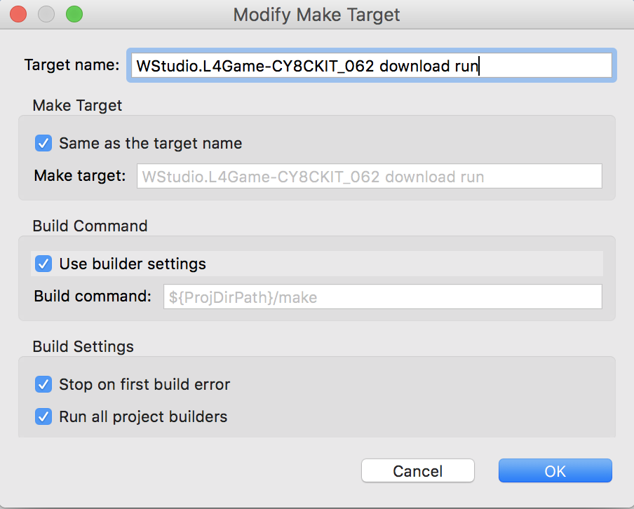
Create a make target for this project
Update GameThread.h to Define the GUI Messages

All of the threads in the system (CapSense, Bluetooth, and WiFi) will control the paddle and the button by sending messages to an RTOS queue.  In gameThread.h we will add a definition of that message.  The message is just a structure with two values – which GUI element and what value to send.

#pragma once
#include "wiced.h"

typedef enum {
    MSG_POSITION,
    MSG_BUTTON0,
    MSG_BUTTON1,
} game_evt_t;

typedef struct {
    game_evt_t evt;
    uint32_t val;
} game_msg_t;

void gameThread(wiced_thread_arg_t arg);

Fix main.c to Create the Queue

I typically believe that the RTOS primitives should be owned by the main.c.  To do this edit main.c and fix the includes.

#include "GameThread.h"
#include "wiced.h"
#include "CapSenseThread.h"
#include "SystemGlobal.h"

Then define the queue variable “paddleQueue” which I should have names “guiQueue” but it is way to late to fix it now — oh well.

/******************************************************
 *               Variable Definitions
 ******************************************************/

wiced_thread_t blinkThreadHandle;
wiced_thread_t capSenseThreadHandle;
wiced_thread_t gameThreadHandle;
wiced_queue_t paddleQueue;

Create the queue

void application_start( )
{
    wiced_init( );
    wiced_rtos_init_queue(&paddleQueue,"paddleQueue",sizeof(game_msg_t),10);
    wiced_rtos_create_thread(&blinkThreadHandle,7,"Blink Thread",pdlBlinkThread,500,0);
    wiced_rtos_create_thread(&capSenseThreadHandle,7,"CapSense Thread",capSenseThread,1024,0);
    wiced_rtos_create_thread(&gameThreadHandle,7,"game Thread",gameThread,4096,0);
 }

Create SystemGlobal.h

Each of the threads in the system need to have access to the paddleQueue.  In order to do that create a file called SystemGlobal.h and extern the variable to give them that access.

#pragma once

extern wiced_queue_t paddleQueue;

Updating the CapSenseThread to send GUI messages

Remember that when we setup the CapSenseThread originally, it just printed out the values.  Let’s fix it so send messages.  So, edit CapSenseThread.c.

  1. Add a message variable (line 8)
  2. Fix the button0 and button 1 to make and send RTOS messages (lines 20/21 and 26/27)
  3. Fix the slider to send the position (lines 33-35)
#include "wiced.h"
#include "GameThread.h"
#include "SystemGlobal.h"

void capSenseThread(wiced_thread_arg_t arg)
{

    game_msg_t msg;

    CapSense_Start();
    CapSense_ScanAllWidgets();
    while(1)
    {
        if(!CapSense_IsBusy())
        {

            CapSense_ProcessAllWidgets();
            if(CapSense_IsWidgetActive(CapSense_BUTTON0_WDGT_ID))
            {
                msg.evt = MSG_BUTTON0;
                wiced_rtos_push_to_queue(&paddleQueue,&msg,0);
            }

            if(CapSense_IsWidgetActive(CapSense_BUTTON1_WDGT_ID))
            {
                msg.evt = MSG_BUTTON1;
                wiced_rtos_push_to_queue(&paddleQueue,&msg,0);
            }

            uint32_t val = CapSense_GetCentroidPos(CapSense_LINEARSLIDER0_WDGT_ID);
            if(val < 0xFFFF)
            {
                msg.evt = MSG_POSITION;
                msg.val = val;
                wiced_rtos_push_to_queue(&paddleQueue,&msg,0);
            }
            CapSense_ScanAllWidgets();
        }
        wiced_rtos_delay_milliseconds(25); // Poll every 25ms (actual scan time ~8ms)
    }
}

Update the includes in GameThread.c

Now let’s fix GameThread.c.  Start by editing the includes to add a new file called “SystemGlobal.h” which contains the global variable for the GUI queue.

#include "GameThread.h"
#include "cy_tft_display.h"
#include "SystemGlobal.h"
#include "ugui.h"

Add some #define macros in GameThread.c

There are a number of constants which I use in the game.  In this section I use #define macros to define them.

#define UPDATE_SCREEN_TIME (20) // Update the screen every 20ms
#define SPEED (2)
#define SCREEN_X (320)
#define SCREEN_Y (240)
#define TOP_FIELD (21)
#define PD_WIDTH (10)
#define PD_LEN (70)
#define DOTS (3)
#define PADDLE0_COLOR (C_BLUE)
#define BALL_COLOR (C_GREEN)
#define BALL_SIZE (10)

Add a State Machine for the Game & Define Paddle Movement

Open up GameThread.c – all of the game control functions will go there.

There will be four screens in the game.  A splash screen to display Cypress and Mouser, a Ready Player 1 Screen, the actual game screen and a game over screen.

In addition the paddle can move a little bit at a time (increment) or jump directly to the position (absolute)

// States of the game
typedef enum {
    GS_SPLASH,
    GS_START,
    GS_RUNNING,
    GS_OVER
} game_state_t;

// Methods to move the paddle
typedef enum {
    PADDLE_INCREMENT,
    PADDLE_ABSOLUTE
} paddle_update_t;

Fix the gameState statemachine

In the splash screen I need to set the state machine to GS_SPLASH

static void displaySplashScreen()
{
    gameState = GS_SPLASH;
    UG_FontSelect( &FONT_22X36 );
    UG_PutStringCenter(SCREEN_X/2,SCREEN_Y/5,22,36,"Cypress");
    UG_PutStringCenter(SCREEN_X/2,SCREEN_Y/5*2,22,36,"Mouser");
    UG_PutStringCenter(SCREEN_X/2,SCREEN_Y/5*3,22,36,"PSoC 6");
    UG_PutStringCenter(SCREEN_X/2,SCREEN_Y/5*4,22,36,"WICED 4343");

    wiced_rtos_delay_milliseconds(2000);
}

In the start screen I need to set the state machine to GS_START

// Display the Start Screen
static void  displayStartScreen()
{
    gameState = GS_START;
    UG_FillScreen( C_BLACK );
    UG_FontSelect( &FONT_22X36 );
    UG_PutStringCenter(SCREEN_X/2,SCREEN_Y/2 -2 - 18 ,22,36,"Ready");
    UG_PutStringCenter(SCREEN_X/2,SCREEN_Y/2 + 2 + 18 ,22,36,"Player 1");
    displayStartButton();
}

Make Forward Declarations for Functions

You should define the functions in advance of using them

/******************************************************
 *               Static Function Declarations
 ******************************************************/
static void UG_PutStringCenter(uint32_t x, uint32_t y, uint32_t fontx, uint32_t fonty,char *string);
static void displaySplashScreen();
static void displayStartButton();
static void  displayStartScreen();
static void displayScore();
static void displaySpeed();
static void endGame();
static inline uint32_t calcPaddleTop();
static inline uint32_t calcPaddleBottom();
static void updatePaddle(paddle_update_t type);
static void updateBall();
static void updateScreen(void *arg);

Create some variables to maintain game state

The updateScreenTimer is used while the game is running to call the updateScreen every 20ms.  The rest of the variables are self explanatory.

/******************************************************
 *               Variable Definitions
 ******************************************************/
static UG_GUI   gui;
static wiced_timer_t updateScreenTimer;

static uint32_t gameScore;
static game_state_t gameState;

// position of the paddle
static uint32_t paddle0_desire_pos=0;
static uint32_t paddle0_cur_pos=0;

// Position, direction and speed of the ball
static uint32_t ballx,bally;
static int32_t ballXdir, ballYdir;
static uint32_t ballSpeed;

Add Display Functions for the Score & Speed

These two functions print the speed and score at the top of the screen.

// This function displays the score
static void displayScore()
{
    char buff[10];
    sprintf(buff,"%2X",(unsigned int)gameScore);
    UG_FontSelect(&FONT_12X20);
    UG_PutString( 75, 0, buff);
}

// This function displays the speed
static void displaySpeed()
{
    char buff[10];
    sprintf(buff,"%2X",(unsigned int)ballSpeed-1);
    UG_FontSelect(&FONT_12X20);
    UG_PutString( 275, 0, buff);
}

Add Function to Start the Game

When the game needs to start you:

  1. Reset the score
  2. Set the paddle position
  3. Move the ball to the middle of the paddle
  4. Set the ball to move to the right and down
  5. Clear the screen, display score and speed
  6. Start the game running
// This function initializes everything and starts a new game
static void startGame()
{
    gameScore = 0;

    paddle0_desire_pos = 50; // start the game with the paddle moving
    paddle0_cur_pos = 0;

    ballx = PD_WIDTH ;                   // start the ball on the paddle on the right of the screen
    bally  = calcPaddleTop() + PD_LEN/2; // start the ball in the middle of the paddle

    ballSpeed = SPEED;

    ballXdir = ballSpeed;
    ballYdir = ballSpeed;

    UG_FillScreen( C_BLACK );  // clear screen
    UG_FontSelect(&FONT_12X20);
    UG_PutString( 0, 0,  "Score:");
    displayScore();
    UG_PutString(200,0,"Speed:");
    displaySpeed();
    UG_DrawLine(0,20,SCREEN_X,20,C_RED); // red line under text to represent top of play screen

    gameState = GS_RUNNING;
    wiced_rtos_start_timer(&updateScreenTimer); // Timer to update screen
}

Add Function to End the Game

When the game is over you should:

  1. Move the game state to over
  2. Stop the timer
  3. Display game over
  4. Display press button 0 to start
// Stop the game
static void endGame()
{
    gameState = GS_OVER;
    wiced_rtos_stop_timer(&updateScreenTimer);
    UG_FontSelect( &FONT_22X36 );
    UG_PutStringCenter(SCREEN_X/2,SCREEN_Y/2,22,36,"Game Over");
    displayStartButton();
}

Add Helper Functions to Calculate Paddle Top & Bottom

There are two places where you need to know the position of the Paddle.  Specifically:

  1. To draw the paddle
  2. To figure out if the ball hit the paddle or not.

These two functions calculate the pixel position of the top and bottom of the paddle based on it current position

// Figure out the y position of the top of the paddle
static inline uint32_t calcPaddleTop()
{
    return (paddle0_cur_pos)*DOTS+TOP_FIELD;
}

// Figure out the y position of the bottom of the paddle
static inline uint32_t calcPaddleBottom()
{
    return (paddle0_cur_pos)*DOTS+PD_LEN+TOP_FIELD;
}

Add a Function to Update & Draw the Paddle

While the game is running you need the paddle to move.  There are two methods:

  1. Absolute just moves the current position immediately to the desired position.
  2. Incremental, which moves the paddle a little bit towards the desired position.
// Move the paddle either to : PADDLE_INCREMENT the next location or PADDLE_ABSOLUTE - final location
static void updatePaddle(paddle_update_t type)
{
    // If the paddle is where it is supposed to be then just return
    if(paddle0_cur_pos == paddle0_desire_pos)
        return;

    // erase the current paddle
    UG_FillFrame(0,calcPaddleTop(),PD_WIDTH,calcPaddleBottom(),C_BLACK);

    switch (type)
    {

    case PADDLE_INCREMENT:

        if(paddle0_cur_pos < paddle0_desire_pos)
            paddle0_cur_pos += SPEED;
        else
            paddle0_cur_pos -= SPEED;

        // If the paddle is within one move of the final spot, put it there
        if(abs((int)paddle0_cur_pos-(int)paddle0_desire_pos) < SPEED)
            paddle0_cur_pos = paddle0_desire_pos;
        break;

    case PADDLE_ABSOLUTE:
        paddle0_cur_pos = paddle0_desire_pos;
        break;
    }
    // draw the paddle
    UG_FillFrame(0,calcPaddleTop(),PD_WIDTH,calcPaddleBottom(),PADDLE0_COLOR);
}

Add a function to update and draw the ball

You need a function to:

  1. Move the ball
  2. Figure out if it hit the right/left/top/bottom of the screen and do the right thing.

When the ball hits one of those surfaces it needs to change direction to either plus or minus.

Every time it hits the paddle the score should increase and possibly speed up.

If it misses the paddle the game is over.

// Move the ball to the next location
static void updateBall()
{
    static const uint32_t BallFudgeFactor=3;

    UG_DrawCircle(ballx,bally,BALL_SIZE,C_BLACK);

    ballx += ballXdir;
    bally += ballYdir;

    // Check to see if the ball hit the far right side
    if(ballx > SCREEN_X - BALL_SIZE)
    {

        ballx = SCREEN_X - BALL_SIZE;
        ballXdir = -ballSpeed;
    }

    // check to see if the ball hit the far left side... or the paddle
    if(ballx < (BALL_SIZE + PD_WIDTH + BallFudgeFactor))
    {
        // See if the ball missed the paddle
        if(bally + BALL_SIZE < calcPaddleTop() || bally - BALL_SIZE > calcPaddleBottom())
        {
            endGame();
            //WPRINT_APP_INFO(("Missed Paddle\r\n"));
        }

        gameScore = gameScore + 1;
        displayScore();
        if(gameScore % 3 == 0) // Speed up every three hits
        {
            ballSpeed +=1;
            displaySpeed();
        }

        ballx = BALL_SIZE + PD_WIDTH + BallFudgeFactor;
        ballXdir = +ballSpeed;
    }
    // Check to see if the ball hit the top or bottom
    if(bally > SCREEN_Y - BALL_SIZE) // bottom
    {
        bally = SCREEN_Y - BALL_SIZE;
        ballYdir = -ballSpeed;
    }

    if(bally < TOP_FIELD+BALL_SIZE) // top
    {
        bally = BALL_SIZE+TOP_FIELD;
        ballYdir = +ballSpeed;
    }
    UG_DrawCircle(ballx,bally,BALL_SIZE,BALL_COLOR);
}

Create a Function for the Game Timer

An RTOS timer runs every 20ms.  That timer needs a function to move the paddle and move the ball.

// This function is called every UPADTE_SCREEN_TIME milliseconds by the updateScreenTimer
static void updateScreen(void *arg)
{
    updatePaddle(PADDLE_INCREMENT);
    updateBall();
}

Update the Main Game Thread

The main game thread needs to get messages out of the queue and then do the right thing based on the game state.

// Main game thread
void gameThread(wiced_thread_arg_t arg)
{
    game_msg_t msg;

    Cy_TFT_Init();                                             // Init the TFT
    UG_Init( &gui, Cy_TFT_displayDriver, SCREEN_X, SCREEN_Y ); // Connect the driver

    UG_FillScreen( C_BLACK );   // Clear the screen
    UG_SetBackcolor( C_BLACK );
    UG_SetForecolor( C_WHITE );

    wiced_rtos_init_timer(&updateScreenTimer,UPDATE_SCREEN_TIME,updateScreen,0);
    displaySplashScreen();
    displayStartScreen();

    while(1)
    {
        wiced_rtos_pop_from_queue(&paddleQueue,&msg,WICED_WAIT_FOREVER);
        switch(msg.evt)
        {
        case MSG_POSITION:
            if(gameState == GS_RUNNING)
                paddle0_desire_pos = msg.val/2;
            if(gameState == GS_OVER)
            {
                paddle0_desire_pos = msg.val/2;
                updatePaddle(PADDLE_ABSOLUTE);
            }
            break;

        case MSG_BUTTON0:
            if(gameState == GS_OVER || gameState == GS_START)
                startGame();
            break;
        case MSG_BUTTON1:
            break;
        }
    }
}

Program and Test

Now that it is all done… program and test it.

GameThread.c

Here is the whole thread is here so you can copy/paste it into your file.

#include "GameThread.h"
#include "cy_tft_display.h"
#include "SystemGlobal.h"
#include "ugui.h"
/******************************************************
*                      Macros
******************************************************/
#define UPDATE_SCREEN_TIME (20) // Update the screen every 20ms
#define SPEED (2)
#define SCREEN_X (320)
#define SCREEN_Y (240)
#define TOP_FIELD (21)
#define PD_WIDTH (10)
#define PD_LEN (70)
#define DOTS (3)
#define PADDLE0_COLOR (C_BLUE)
#define BALL_COLOR (C_GREEN)
#define BALL_SIZE (10)
/******************************************************
*                    Constants
******************************************************/
/******************************************************
*                   Enumerations
******************************************************/
/******************************************************
*                 Type Definitions
******************************************************/
// States of the game
typedef enum {
GS_SPLASH,
GS_START,
GS_RUNNING,
GS_OVER
} game_state_t;
// Methods to move the paddle
typedef enum {
PADDLE_INCREMENT,
PADDLE_ABSOLUTE
} paddle_update_t;
/******************************************************
*                    Structures
******************************************************/
/******************************************************
*               Static Function Declarations
******************************************************/
static void UG_PutStringCenter(uint32_t x, uint32_t y, uint32_t fontx, uint32_t fonty,char *string);
static void displaySplashScreen();
static void displayStartButton();
static void  displayStartScreen();
static void displayScore();
static void displaySpeed();
static void endGame();
static inline uint32_t calcPaddleTop();
static inline uint32_t calcPaddleBottom();
static void updatePaddle(paddle_update_t type);
static void updateBall();
static void updateScreen(void *arg);
/******************************************************
*               Variable Definitions
******************************************************/
static UG_GUI   gui;
static wiced_timer_t updateScreenTimer;
static uint32_t gameScore;
static game_state_t gameState;
// position of the paddle
static uint32_t paddle0_desire_pos=0;
static uint32_t paddle0_cur_pos=0;
// Position, direction and speed of the ball
static uint32_t ballx,bally;
static int32_t ballXdir, ballYdir;
static uint32_t ballSpeed;
/******************************************************
*               Functions
******************************************************/
// ARH Function to put text in the center of a point (UG_PutString does upper left)
static void UG_PutStringCenter(uint32_t x, uint32_t y, uint32_t fontx, uint32_t fonty,char *string)
{
y = y - fonty/2;
x = x - (strlen(string)/2)*fontx;
if(strlen(string)%2)
x = x - fontx/2;
UG_PutString(x,y,string);
}
// Display the splash screen
static void displaySplashScreen()
{
gameState = GS_SPLASH;
UG_FontSelect( &FONT_22X36 );
UG_PutStringCenter(SCREEN_X/2,SCREEN_Y/5,22,36,"Cypress");
UG_PutStringCenter(SCREEN_X/2,SCREEN_Y/5*2,22,36,"Mouser");
UG_PutStringCenter(SCREEN_X/2,SCREEN_Y/5*3,22,36,"PSoC 6");
UG_PutStringCenter(SCREEN_X/2,SCREEN_Y/5*4,22,36,"WICED 4343");
wiced_rtos_delay_milliseconds(2000);
}
// This function displays the start button message
static void displayStartButton()
{
UG_FontSelect(&FONT_12X20);
UG_PutStringCenter(SCREEN_X/2 , SCREEN_Y - 30 ,12,22,  "Press B0 To Start");
}
// Display the Start Screen
static void  displayStartScreen()
{
gameState = GS_START;
UG_FillScreen( C_BLACK );
UG_FontSelect( &FONT_22X36 );
UG_PutStringCenter(SCREEN_X/2,SCREEN_Y/2 -2 - 18 ,22,36,"Ready");
UG_PutStringCenter(SCREEN_X/2,SCREEN_Y/2 + 2 + 18 ,22,36,"Player 1");
displayStartButton();
}
// This function displays the score
static void displayScore()
{
char buff[10];
sprintf(buff,"%2X",(unsigned int)gameScore);
UG_FontSelect(&FONT_12X20);
UG_PutString( 75, 0, buff);
}
// This function displays the speed
static void displaySpeed()
{
char buff[10];
sprintf(buff,"%2X",(unsigned int)ballSpeed-1);
UG_FontSelect(&FONT_12X20);
UG_PutString( 275, 0, buff);
}
// This function initializes everything and starts a new game
static void startGame()
{
gameScore = 0;
paddle0_desire_pos = 50; // start the game with the paddle moving
paddle0_cur_pos = 0;
ballx = PD_WIDTH ;                   // start the ball on the paddle on the right of the screen
bally  = calcPaddleTop() + PD_LEN/2; // start the ball in the middle of the paddle
ballSpeed = SPEED;
ballXdir = ballSpeed;
ballYdir = ballSpeed;
UG_FillScreen( C_BLACK );  // clear screen
UG_FontSelect(&FONT_12X20);
UG_PutString( 0, 0,  "Score:");
displayScore();
UG_PutString(200,0,"Speed:");
displaySpeed();
UG_DrawLine(0,20,SCREEN_X,20,C_RED); // red line under text to represent top of play screen
gameState = GS_RUNNING;
wiced_rtos_start_timer(&updateScreenTimer); // Timer to update screen
}
// Stop the game
static void endGame()
{
gameState = GS_OVER;
wiced_rtos_stop_timer(&updateScreenTimer);
UG_FontSelect( &FONT_22X36 );
UG_PutStringCenter(SCREEN_X/2,SCREEN_Y/2,22,36,"Game Over");
displayStartButton();
}
// Figure out the y position of the top of the paddle
static inline uint32_t calcPaddleTop()
{
return (paddle0_cur_pos)*DOTS+TOP_FIELD;
}
// Figure out the y position of the bottom of the paddle
static inline uint32_t calcPaddleBottom()
{
return (paddle0_cur_pos)*DOTS+PD_LEN+TOP_FIELD;
}
// Move the paddle either to : PADDLE_INCREMENT the next location or PADDLE_ABSOLUTE - final location
static void updatePaddle(paddle_update_t type)
{
// If the paddle is where it is supposed to be then just return
if(paddle0_cur_pos == paddle0_desire_pos)
return;
// erase the current paddle
UG_FillFrame(0,calcPaddleTop(),PD_WIDTH,calcPaddleBottom(),C_BLACK);
switch (type)
{
case PADDLE_INCREMENT:
if(paddle0_cur_pos < paddle0_desire_pos)
paddle0_cur_pos += SPEED;
else
paddle0_cur_pos -= SPEED;
// If the paddle is within one move of the final spot, put it there
if(abs((int)paddle0_cur_pos-(int)paddle0_desire_pos) < SPEED)
paddle0_cur_pos = paddle0_desire_pos;
break;
case PADDLE_ABSOLUTE:
paddle0_cur_pos = paddle0_desire_pos;
break;
}
// draw the paddle
UG_FillFrame(0,calcPaddleTop(),PD_WIDTH,calcPaddleBottom(),PADDLE0_COLOR);
}
// Move the ball to the next location
static void updateBall()
{
static const uint32_t BallFudgeFactor=3;
UG_DrawCircle(ballx,bally,BALL_SIZE,C_BLACK);
ballx += ballXdir;
bally += ballYdir;
// Check to see if the ball hit the far right side
if(ballx > SCREEN_X - BALL_SIZE)
{
ballx = SCREEN_X - BALL_SIZE;
ballXdir = -ballSpeed;
}
// check to see if the ball hit the far left side... or the paddle
if(ballx < (BALL_SIZE + PD_WIDTH + BallFudgeFactor))
{
// See if the ball missed the paddle
if(bally + BALL_SIZE < calcPaddleTop() || bally - BALL_SIZE > calcPaddleBottom())
{
endGame();
//WPRINT_APP_INFO(("Missed Paddle\r\n"));
}
gameScore = gameScore + 1;
displayScore();
if(gameScore % 3 == 0) // Speed up every three hits
{
ballSpeed +=1;
displaySpeed();
}
ballx = BALL_SIZE + PD_WIDTH + BallFudgeFactor;
ballXdir = +ballSpeed;
}
// Check to see if the ball hit the top or bottom
if(bally > SCREEN_Y - BALL_SIZE) // bottom
{
bally = SCREEN_Y - BALL_SIZE;
ballYdir = -ballSpeed;
}
if(bally < TOP_FIELD+BALL_SIZE) // top
{
bally = BALL_SIZE+TOP_FIELD;
ballYdir = +ballSpeed;
}
UG_DrawCircle(ballx,bally,BALL_SIZE,BALL_COLOR);
}
// This function is called every UPADTE_SCREEN_TIME milliseconds by the updateScreenTimer
static void updateScreen(void *arg)
{
updatePaddle(PADDLE_INCREMENT);
updateBall();
}
// Main game thread
void gameThread(wiced_thread_arg_t arg)
{
game_msg_t msg;
Cy_TFT_Init();                                             // Init the TFT
UG_Init( &gui, Cy_TFT_displayDriver, SCREEN_X, SCREEN_Y ); // Connect the driver
UG_FillScreen( C_BLACK );   // Clear the screen
UG_SetBackcolor( C_BLACK );
UG_SetForecolor( C_WHITE );
wiced_rtos_init_timer(&updateScreenTimer,UPDATE_SCREEN_TIME,updateScreen,0);
displaySplashScreen();
displayStartScreen();
while(1)
{
wiced_rtos_pop_from_queue(&paddleQueue,&msg,WICED_WAIT_FOREVER);
switch(msg.evt)
{
case MSG_POSITION:
if(gameState == GS_RUNNING)
paddle0_desire_pos = msg.val/2;
if(gameState == GS_OVER)
{
paddle0_desire_pos = msg.val/2;
updatePaddle(PADDLE_ABSOLUTE);
}
break;
case MSG_BUTTON0:
if(gameState == GS_OVER || gameState == GS_START)
startGame();
break;
case MSG_BUTTON1:
break;
}
}
}
 

Mouser PSoC 6-WiFi-BT L3: Using the CY8CKIT-028-TFT Shield

Designing low-power, cloud-connected IoT devices with PSoC® 6 MCU’s and WICED® Wi-Fi/Bluetooth

Summary

In this lesson we will start making the game.  The first thing that it will need is a display and we will use the CY8CKIT-028-TFT.  In order to talk to the display we will use a library built into WICED called ugui.  That library needs a driver configuration which we will copy of out the code example we provide.  Finally we will start building a thread called the “GameThread” which will actually make up the game.

  1. Download CE222494_PSoC6_WICED_WiFi
  2. Copy the L2CapSense into L3CapSenseTft
  3. Copy cy_tft_display.c/h into the project
  4. Make a file GameThread.h
  5. Make a file GameThread.c
  6. Rename L2CapSense.mk to be L3CapSenseTft.mk & Fix
  7. Update main.c
  8. Test

Download CE222494_PSoC6_WICED_WiFi

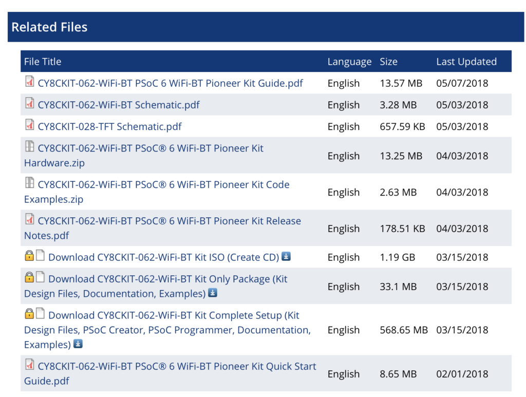
If you click on the CY8CKIT-062-WiFi-BT webpage you will find that there are a bunch of files which are associated with the development kit, including CY8CKIT-062-WiFi-BT PSoC® 6 WiFi-BT Pioneer Kit Code Examples.zip.

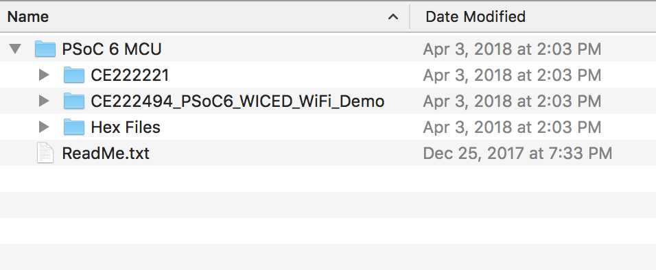
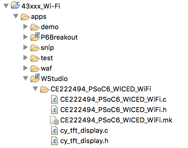
Download that folder, then copy the directory into your WICED Studio Apps/WStudio folder.

Once you do that it should look like this:

Copy L3CapSense into L3CapSenseTft

Now copy/paste the L2CapSense project into a new project called L3CapSenseTft

Copy cy_tft_display.c/h into the project

Open up the CE222494 code example directory and copy the two files cy_tft_display.c andcy_tft_display.c which are drivers for the ugui library and then paste them into your new project L3CapSenseTft.

Make a file GameThread.h

Create a new file called GamThread.h and a definition of the GameThread which will be used by the main.c to get the game thread going.

#pragma once
#include "wiced.h"
void gameThread(wiced_thread_arg_t arg);

Make a file GameThread.c

Now create a file called GameThread.c it will have 5 functions.  Here is the whole file to make it simpler to copy and paste, but Ill explain each function one by one

#include "GameThread.h"
#include "cy_tft_display.h"
#define SCREEN_X (320)
#define SCREEN_Y (240)
static UG_GUI   gui;
// ARH Function to put text in the center of a point (UG_PutString does upper left)
static void UG_PutStringCenter(uint32_t x, uint32_t y, uint32_t fontx, uint32_t fonty,char *string)
{
y = y - fonty/2;
x = x - (strlen(string)/2)*fontx;
if(strlen(string)%2)
x = x - fontx/2;
UG_PutString(x,y,string);
}
// Display the splash screen
static void displaySplashScreen()
{
UG_FontSelect( &FONT_22X36 );
UG_PutStringCenter(SCREEN_X/2,SCREEN_Y/5,22,36,"Cypress");
UG_PutStringCenter(SCREEN_X/2,SCREEN_Y/5*2,22,36,"Mouser");
UG_PutStringCenter(SCREEN_X/2,SCREEN_Y/5*3,22,36,"PSoC 6");
UG_PutStringCenter(SCREEN_X/2,SCREEN_Y/5*4,22,36,"WICED 4343");
wiced_rtos_delay_milliseconds(2000);
}
// This function displays the start button message
static void displayStartButton()
{
UG_FontSelect(&FONT_12X20);
UG_PutStringCenter(SCREEN_X/2 , SCREEN_Y - 30 ,12,22,  "Press B0 To Start");
}
// Display the Start Screen
static void  displayStartScreen()
{
UG_FillScreen( C_BLACK );
UG_FontSelect( &FONT_22X36 );
UG_PutStringCenter(SCREEN_X/2,SCREEN_Y/2 -2 - 18 ,22,36,"Ready");
UG_PutStringCenter(SCREEN_X/2,SCREEN_Y/2 + 2 + 18 ,22,36,"Player 1");
displayStartButton();
}
// Main game thread
void gameThread(wiced_thread_arg_t arg)
{
Cy_TFT_Init();                                             // Init the TFT
UG_Init( &gui, Cy_TFT_displayDriver, SCREEN_X, SCREEN_Y ); // Connect the driver
UG_FillScreen( C_BLACK );   // Clear the screen
UG_SetBackcolor( C_BLACK );
UG_SetForecolor( C_WHITE );
displaySplashScreen();
displayStartScreen();
while(1)
{
wiced_rtos_delay_milliseconds(1000);
}
}

The main game thread function is: void gameThread(wiced_thread_arg_t arg).  This function

  1. Initializes the TFT
  2. Initializes the UGUI library
  3. Clears the screen (by setting it all black)
  4. Sets the colors to draw white on black
  5. Displays the splash screen (which takes 2 seconds)
  6. Displays the start screen
  7. Waits until the end of time
// Main game thread
void gameThread(wiced_thread_arg_t arg)
{
Cy_TFT_Init();                                             // Init the TFT
UG_Init( &gui, Cy_TFT_displayDriver, SCREEN_X, SCREEN_Y ); // Connect the driver
UG_FillScreen( C_BLACK );   // Clear the screen
UG_SetBackcolor( C_BLACK );
UG_SetForecolor( C_WHITE );
displaySplashScreen();
displayStartScreen();
while(1)
{
wiced_rtos_delay_milliseconds(1000);
}
}

The function displaySplashScreen simply sets the font, then draws 4 text strings, then waits for a few seconds… then moves on

// Display the splash screen
static void displaySplashScreen()
{
UG_FontSelect( &FONT_22X36 );
UG_PutStringCenter(SCREEN_X/2,SCREEN_Y/5,22,36,"Cypress");
UG_PutStringCenter(SCREEN_X/2,SCREEN_Y/5*2,22,36,"Mouser");
UG_PutStringCenter(SCREEN_X/2,SCREEN_Y/5*3,22,36,"PSoC 6");
UG_PutStringCenter(SCREEN_X/2,SCREEN_Y/5*4,22,36,"WICED 4343");
wiced_rtos_delay_milliseconds(2000);
}

The displayStartScreen put the “Ready Player 1 on the screen” and then tells the user to press the B0 to start the game.

// This function displays the start button message
static void displayStartButton()
{
UG_FontSelect(&FONT_12X20);
UG_PutStringCenter(SCREEN_X/2 , SCREEN_Y - 30 ,12,22,  "Press B0 To Start");
}
// Display the Start Screen
static void  displayStartScreen()
{
UG_FillScreen( C_BLACK );
UG_FontSelect( &FONT_22X36 );
UG_PutStringCenter(SCREEN_X/2,SCREEN_Y/2 -2 - 18 ,22,36,"Ready");
UG_PutStringCenter(SCREEN_X/2,SCREEN_Y/2 + 2 + 18 ,22,36,"Player 1");
displayStartButton();
}

The U8G_PutString function uses coordinates x and y to set the upper left of the text.  For formatting purposes it is easier for me to think about the middle of the string.  This function just calculates the upper left (x,y) given the middle center (x,y).  To do this you need to also know the (x,y) size of the font.

static void UG_PutStringCenter(uint32_t x, uint32_t y, uint32_t fontx, uint32_t fonty,char *string)

// ARH Function to put text in the center of a point (UG_PutString does upper left)
static void UG_PutStringCenter(uint32_t x, uint32_t y, uint32_t fontx, uint32_t fonty,char *string)
{
y = y - fonty/2;
x = x - (strlen(string)/2)*fontx;
if(strlen(string)%2)
x = x - fontx/2;
UG_PutString(x,y,string);
}

Rename L2CapSense.mk to be L3CapSenseTft.mk & Fix

To make this build we need to modify the makefile to know about the new thread as well as the tft driver.  In addition we need to tell the linker to link with the graphics library.

NAME := App_WStudio_L3CapSenseTft
$(NAME)_SOURCES := 	main.c \
CapSenseThread.c \
GameThread.c \
cy_tft_display.c
$(NAME)_COMPONENTS := graphics/ugui

Update main.c

In main.c I will:

  1. Include the GameThread.h
  2. Add a variable to hold the gameThreadHandle
  3. Then start the gameThread
#include "wiced.h"
#include "CapSenseThread.h"
#include "GameThread.h"
/******************************************************
*                      Macros
******************************************************/
/******************************************************
*                    Constants
******************************************************/
/******************************************************
*                   Enumerations
******************************************************/
/******************************************************
*                 Type Definitions
******************************************************/
/******************************************************
*                    Structures
******************************************************/
/******************************************************
*               Static Function Declarations
******************************************************/
/******************************************************
*               Variable Definitions
******************************************************/
wiced_thread_t blinkThreadHandle;
wiced_thread_t capSenseThreadHandle;
wiced_thread_t gameThreadHandle;
/******************************************************
*               Function Definitions
******************************************************/
void pdlBlinkThread(wiced_thread_arg_t arg)
{
while(1)
{
Cy_GPIO_Inv(GPIO_PRT0,3);
wiced_rtos_delay_milliseconds(500);
}
}
void application_start( )
{
wiced_init();
WPRINT_APP_INFO(("Started Application\n"));
wiced_rtos_create_thread(&blinkThreadHandle,7,"Blink Thread",pdlBlinkThread,500,0);
wiced_rtos_create_thread(&capSenseThreadHandle,7,"CapSense Thread",capSenseThread,1024,0);
wiced_rtos_create_thread(&gameThreadHandle,7,"game Thread",gameThread,4096,0);
}

Test

Now it is ready to test.  So create a Make Target, then Build and Program.  Hopefully you are now Ready Player 1.


Mouser PSoC 6-WiFi-BT L2 : WICED Studio & CapSense

Designing low-power, cloud-connected IoT devices with PSoC® 6 MCU’s and WICED® Wi-Fi/Bluetooth

Summary

In this lesson we will build your first WICED Studio project (the blinking LED)  and make sure that you can program the development kit.  Then we will update the project to include a thread for managing the CapSense block.  This thread will be carried into the other projects.

To implement this lesson I will follow these steps:

  1. Start WICED Studio 6.2
  2. Select 43xxx
  3. Create a folder called L2CapSense
  4. Create main.c and build a blinking LED thread
  5. Create L2CapSense.mk
  6. Create a make target
  7. Build Program and test it
  8. Create CapSenseThread.c
  9. Create CapSenseThread.h
  10. Update main.c
  11. Update the makefile
  12. Build Program and Test

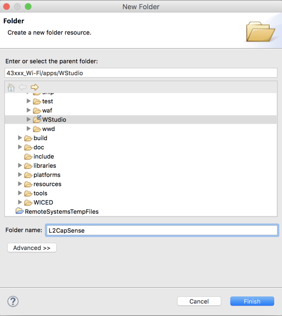
Create the L2CapSense Folder

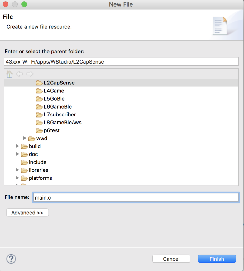
Create main.c

Right click on the folder and create a new file.  Name it L2CapSense

Insert the blinking LED code into main.c

#include "wiced.h"
/******************************************************
*                      Macros
******************************************************/
/******************************************************
*                    Constants
******************************************************/
/******************************************************
*                   Enumerations
******************************************************/
/******************************************************
*                 Type Definitions
******************************************************/
/******************************************************
*                    Structures
******************************************************/
/******************************************************
*               Static Function Declarations
******************************************************/
/******************************************************
*               Variable Definitions
******************************************************/
wiced_thread_t blinkThreadHandle;
/******************************************************
*               Function Definitions
******************************************************/
void pdlBlinkThread(wiced_thread_arg_t arg)
{
while(1)
{
Cy_GPIO_Inv(GPIO_PRT0,3);
wiced_rtos_delay_milliseconds(500);
}
}
void application_start( )
{
WPRINT_APP_INFO(("Started Application\n"));
wiced_rtos_create_thread(&blinkThreadHandle,7,"Blink Thread",pdlBlinkThread,500,0);
}

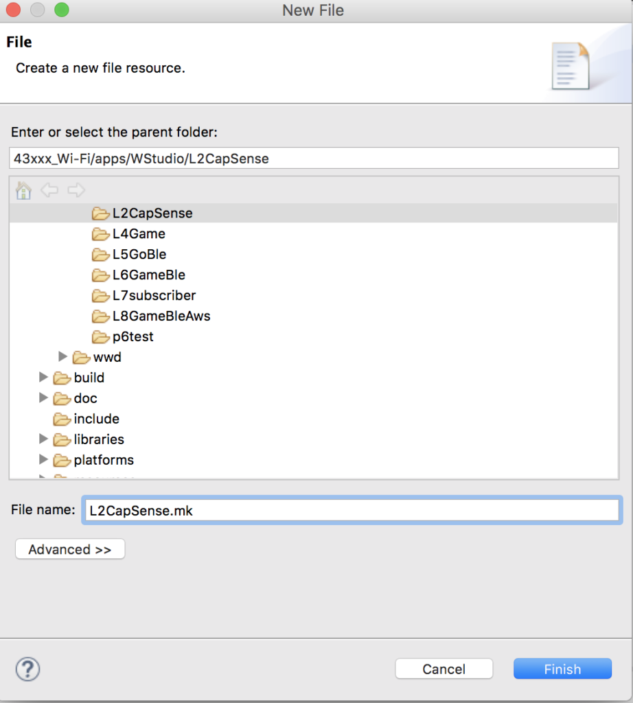
Create L2CapSense.mk

Create a makefile called L2CapSense.mk

Put the build information into the L2CapSense.mk

NAME := App_WStudio_L2CapSense
$(NAME)_SOURCES := 	main.c

Create a Make Target to run the project

Build and Test the Blinking LED

Create/Edit a File called CapSenseThread.c

#include "wiced.h"
void capSenseThread(wiced_thread_arg_t arg)
{
CapSense_Start();
CapSense_ScanAllWidgets();
while(1)
{
if(!CapSense_IsBusy())
{
CapSense_ProcessAllWidgets();
if(CapSense_IsWidgetActive(CapSense_BUTTON0_WDGT_ID))
{
WPRINT_APP_INFO(("Button 0 Active\n"));
}
if(CapSense_IsWidgetActive(CapSense_BUTTON1_WDGT_ID))
{
WPRINT_APP_INFO(("Button 1 Active\n"));
}
uint32_t val = CapSense_GetCentroidPos(CapSense_LINEARSLIDER0_WDGT_ID);
if(val < 0xFFFF)
{
WPRINT_APP_INFO(("Slider = %d\n",(int)val));
}
CapSense_ScanAllWidgets();
}
wiced_rtos_delay_milliseconds(25); // Poll every 25ms (actual scan time ~8ms)
}
}

Create/Edit a File Called CapSenseThread.h

#pragma once
#include "wiced.h"
void capSenseThread(wiced_thread_arg_t arg);

Update main.c

#include "wiced.h"
#include "CapSenseThread.h"

Add a variable to hold the handle for the capSenseThread at the top of main.c

wiced_thread_t capSenseThreadHandle;

Update the main function to start the CapSenseThread

void application_start( )
{
WPRINT_APP_INFO(("Started Application\n"));
wiced_rtos_create_thread(&blinkThreadHandle,7,"Blink Thread",pdlBlinkThread,500,0);
wiced_rtos_create_thread(&capSenseThreadHandle,7,"CapSense Thread",capSenseThread,1024,0);
}

Update the L2CapsenseThread.mk

NAME := App_WStudio_L2CapSense
$(NAME)_SOURCES := 	main.c \
CapSenseThread.c

Build, Program and Test the CapSenseThread


Mouser PSoC 6-WiFi-BT L1 : Developer Resources

Designing low-power, cloud-connected IoT devices with PSoC® 6 MCU’s and WICED® Wi-Fi/Bluetooth

Summary

This is an index of links to all of the PSoC 6 & CYW4343W learning resources.  You can click the links to go the website or see screen captures of the resources.

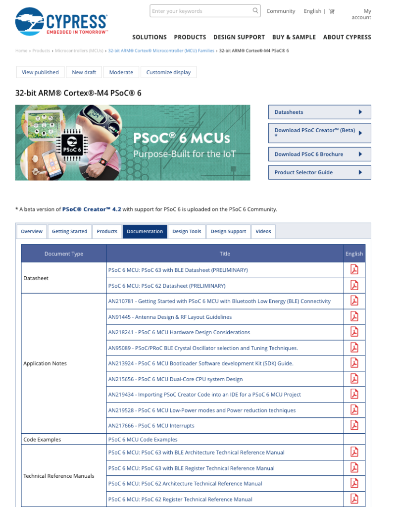
  1. PSoC 6 Product Page
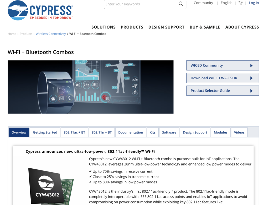
  2. WiFi + Bluetooth Combo Product Page
  3. PSoC 6 Documentation
  4. PSoC 6 Community
  5. Wireless Combo Community
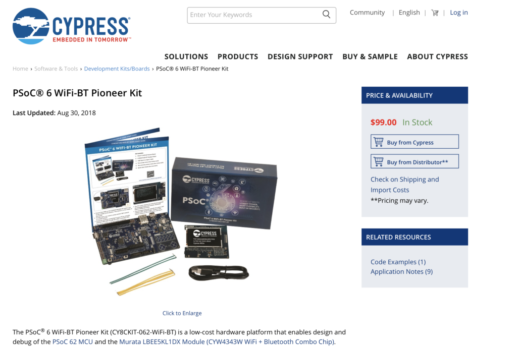
  6. CY8CKIT-062-BT-WiFi Development Kit Product Page
  7. CY8CKIT-062-BT-WiFi Development Kit Guide
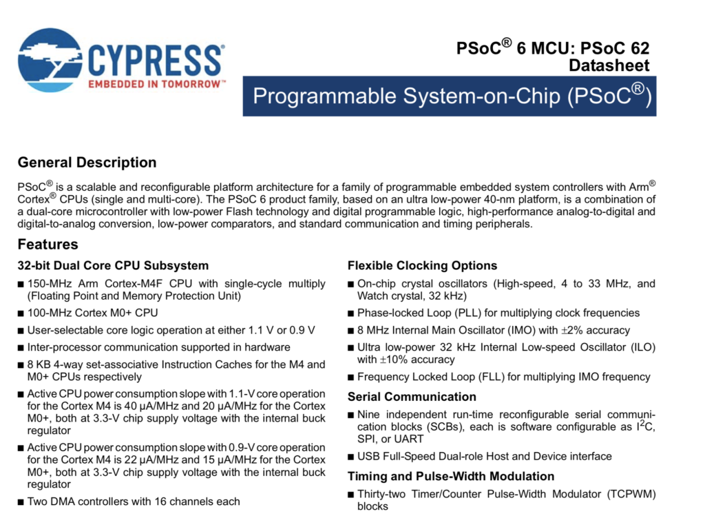
  8. PSoC 6 Datasheet
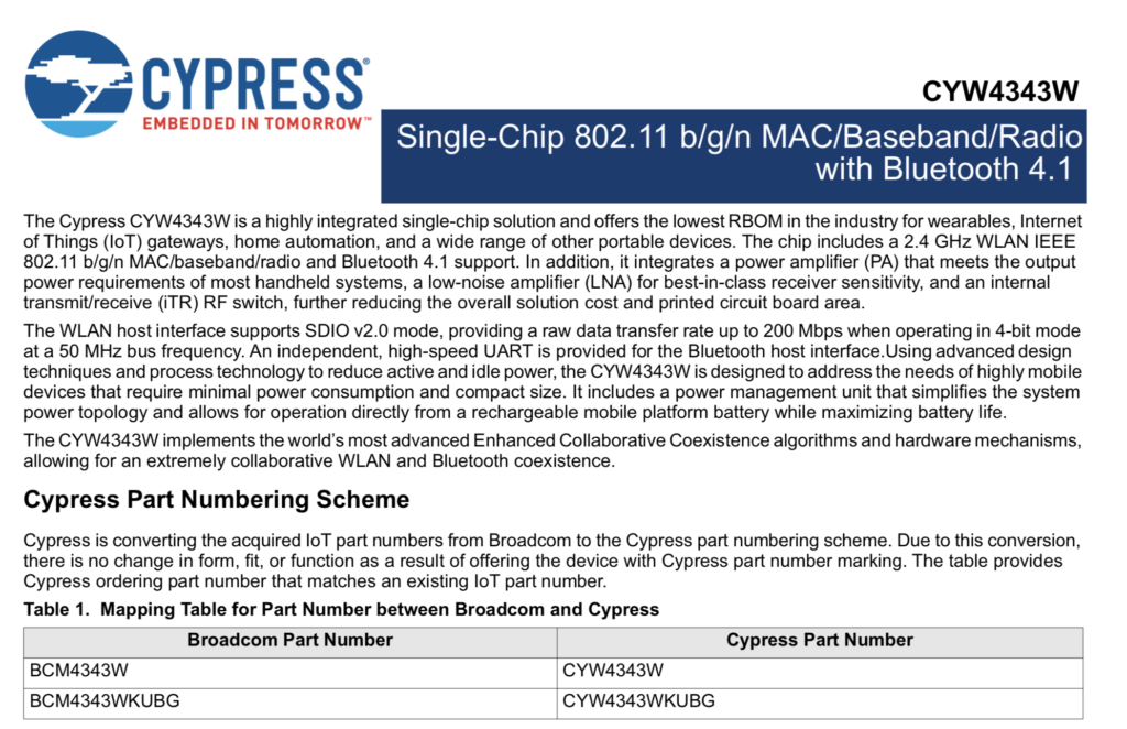
  9. CYW4343W Datasheet
  10. PSoC 6 Technical Reference Manuals
  11. PSoC 6 Application Notes
  12. WiFi + Bluetooth Combo Application Notes
  13. PSoC 6 Code Examples
  14. Video Tutorials
  15. PSoC 6 Knowledge Base
  16. Peripheral Driver Library Documentation (Doxygen)
  17. WICED Documentation

PSoC 6 Product Page

You can find the PSoC 6 Product landing page for PSoC 6 here

WiFi + Bluetooth Combo Page

PSoC 6 Documentation

On the PSoC 6 Product Landing page there is a documentation tab that has links to all of the current documentation.

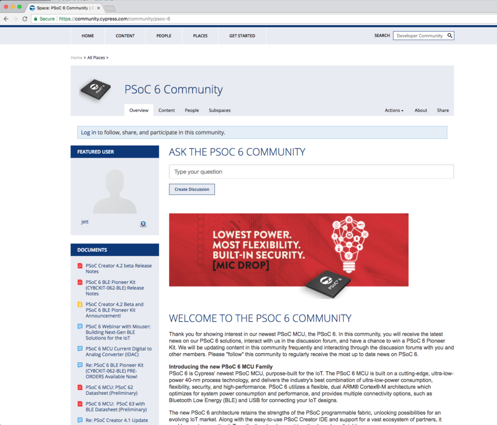
PSoC 6 Community

Cypress has an active development community and forum.  It can be found here.

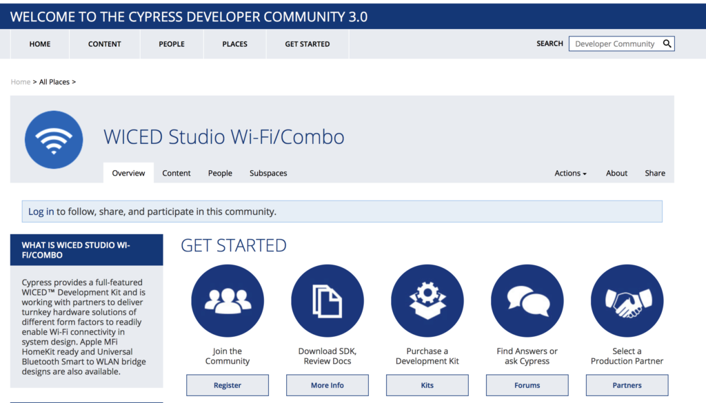
Wireless WiFi + Bluetooth Combo Community

CY8CKIT-062-WiFi-BT Development Kit Web Page

Every Cypress development kit has a web page that contains all of the information about it, including links to the documentation and store.  The CY8CKIT-062-WiFi-BT kit page is here.

CY8CKIT-062-WiFi-BT Development Kit Guide

You can find the development kit guide here.


PSoC 6 Datasheet

The PSoC 6 Datasheet is available on Cypress.com here.


CYW4343W Datasheet

The CYW4343W datasheet can be found here.

PSoC 6 Technical Reference Manual

Each of the PSoC 6 devices has a lengthy discussion of the Technical Resources.  These documents can be found here

PSoC 6 Application Notes

You can get them all on our website… here is a link to the filtered list of PSoC 6 Application Notes.

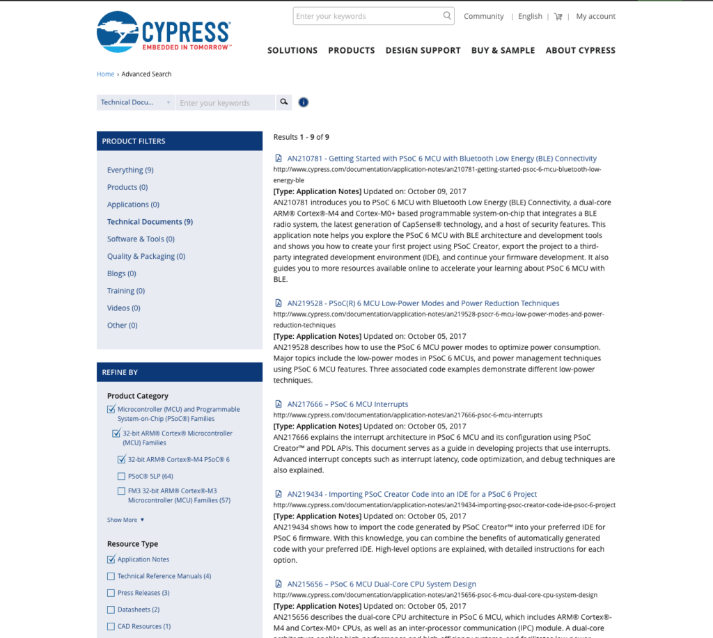
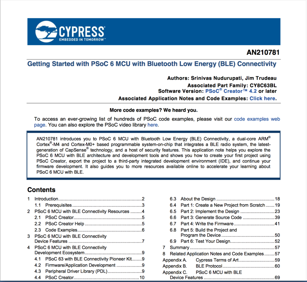
The best application note is always the “Getting Started”.  In this case it is AN210781 “Getting Started with PSoC 6 MCU with Bluetooth Low Energy (BLE) Connectivity”

WiFi + Bluetooth Combo Application Notes

Here is a link to all of the WiFI Bluetooth Combo Application Notes.

PSoC 6 Code Examples

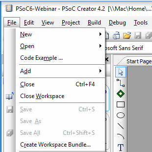
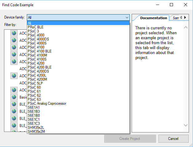
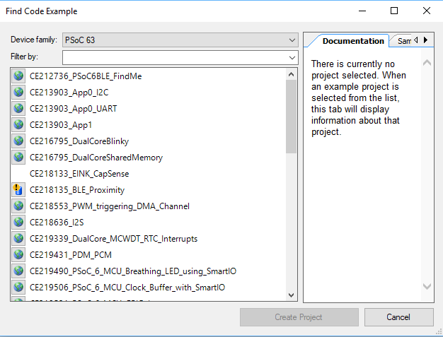
You can find all of the PSoC 6 code examples on the web.  In addition they are built into PSoC Creator.

Or in PSoC Creator:

Videos

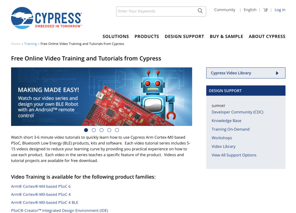
Cypress has made a bunch of videos that take you step by step through an introduction to PSoC 6.  You can find them on the Cypress training website.

PSoC 6 Knowledge Base

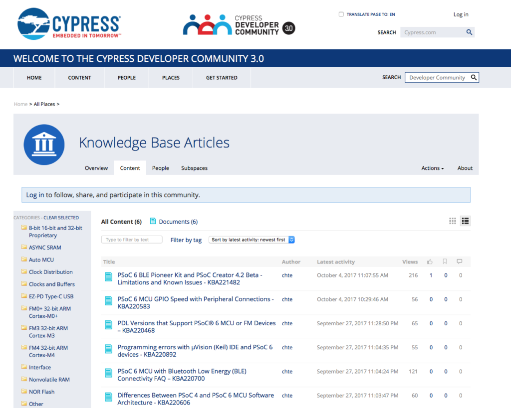
The Cypress technical support team writes “Knowledge Base” articles when there are repeated issues reported by customers.  You can find them here.

Peripheral Driver Library Documentation (Doxygen)

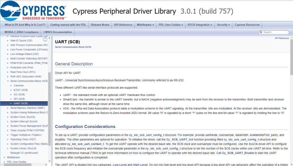
All of the APIs in the PDL are documented in a Doxygen generated HTML document.  You can get there from

  • Help -> Peripheral Driver Library (this link is live only when you have a PSoC 6 project open)
  • Right click on a component -> Open PDL Documentation

IoT Mailbox: An Introduction

Summary

On the days that my newspaper carrier decides to deliver the newspaper, you can be sure that it won’t be there before 4:00am or after 10:00am.  Why do I still get a newspaper?  Because my wife likes it.  The status of the delivery is a constant source of speculation in the morning.  Have you been out to the newspaper box?  Will you go?  etc.  So it seems only logical to make an IoT device that figures out if I have a newspaper.  Obviously this is a bit silly to put as much time and effort as I have into that simple task.  But, doing something cool has it own worth.  And it will give me a chance to use the new WICED XR (extended range) Bluetooth radio module CYBT-483039-02.

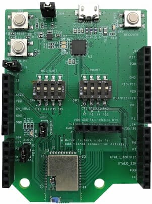
And here is a picture of the new module on the CYBT-483039-EVAL EZ-BT evaluation kit.

For this design I want

  1. A newspaper sensor (not sure what that will be)
  2. Waterproof case
  3. A temperature sensor
  4. A custom circuit board
  5. A solar battery charger
  6. The ability to program and debug the 20719 (which will be acting as a beacon)
  7. An OTA Bootloader
  8. A Real Time Clock
  9. A wifi/ble bridge (inside the house)
  10. Some cloud data capture and display
  11. An iOS App

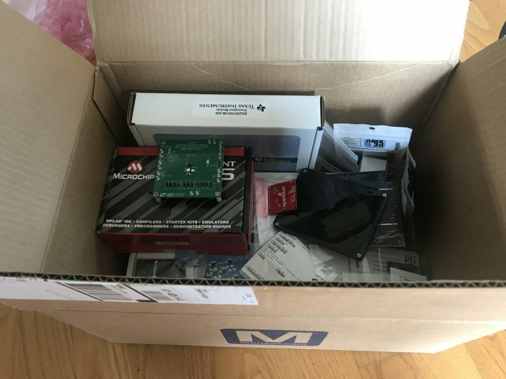
So far, this project has been quite a rabbit hole as I don’t/didn’t know anything about battery power supplies.  Specifically energy harvesting solar powered lithium ion battery chargers and system power supply.  Unfortunately Cypress doesnt make an IC that performs this application … so if you send Mouser a few hundred dollars and they will send you a box of a bunch of different Solar PMIC Evaluation kits, ST, TI, Linear, Analog Devices, and Microchip. (which I will write about in detail later)

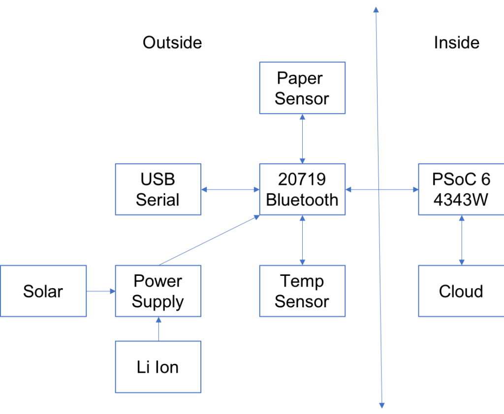
Architecture

Here is a picture of the architecture.

In the next Article I will start the process of learning about Solar Battery Charging PMICs.

Article Description
IoT Mailbox Introduction An introduction to the long series of articles about creating a new IoT System.
IoT Mailbox: Solar Battery Chargers & System Power Supplies

Lesson 1 – WICED Bluetooth: A Tour of the Resources

WICED Bluetooth Using the CYW20719

# Title Comment
0 A Two Hour WICED Bluetooth Class WICED Bluetooth Using the CYW20719 in all its glory
1 Resources Links to all of the Cypress WICED information including videos, application notes etc.
2 Your First Project Making Hello World & the Blinky LED
3 The Super Mux Tool Learning about platforms and the Super Mux Tool
4 Snips Using the example projects to learn Bluetooth
5 Bluetooth Designer Using the tool to customize a project and get going fast
6 The CCCD & Notification Writing back to the Central
7 Advertising  Beacon Building a beacon project to advertise your custom information 
8 Scanner Viewing the world around you
9 Bluetooth Classic SPP Using the Serial Port Profile to Transmit Lots of Data

Source code: 

  • git@github.com:iotexpert/wiced_bt_intro.git
  • https://github.com/iotexpert/wiced_bt_intro


A Tour of the Resources

Cypress is committed to the “Whole Product”.  What that means is that we believe that you should have great software, hardware, dev kits, community etc. experience while using our chip.  So, before we get started Id like to show you all of the learning and development resources available to you.

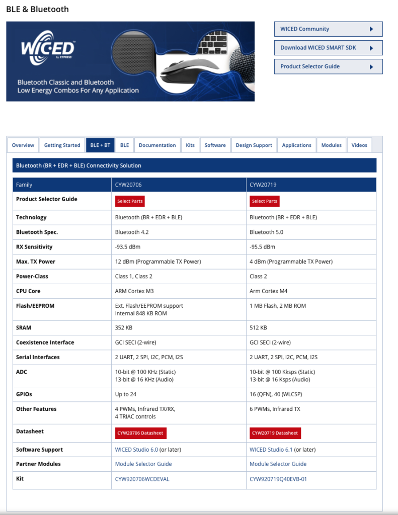
  1. BLE & Bluetooth Connectivity Solutions
  2. WICED CYW20719 Product Page
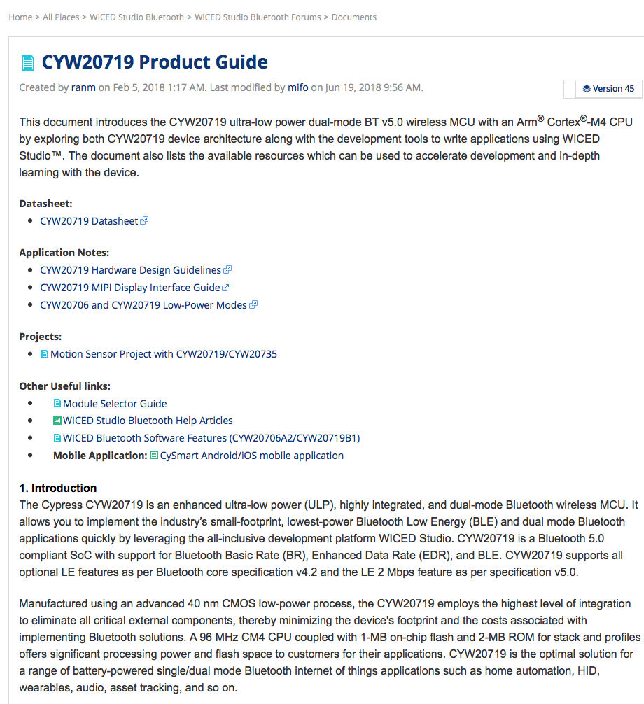
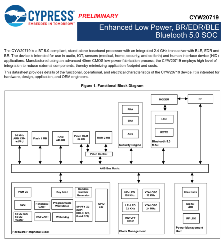
  3. CYW20719 Product Guide
  4. CYW20719 Datasheet
  5. CYW20719 Software Features
  6. WICED Module Selection Guide
  7. CYW920719Q40EVB-01 Development Kit
  8. CYW920719Q40EVB-01 Product Page
  9. CYW920719 Quick Start
  10. CYW920719Q40EVB-01 Evaluation Board User Guide
  11. Cypress Community
  12. WICED Studio Bluetooth Community
  13. WICED Studio Bluetooth Forums
  14. WICED Studio
  15. WICED Studio Bluetooth Example Projects
  16. WICED Studio Documentation
  17. WICED Bluetooth API Guide
  18. WICED README.txt
  19. WICED Studio Release Notes
  20. WICED Studio Technical Brief
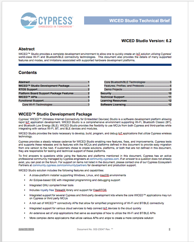
  21. WICED Bluetooth 101

Bluetooth BR+EDR Connectivity Solutions Page

This pages gets to you all of the Cypress WICED BR+EDR+Bluetooth products

WICED CYW20719 Product Page

When you get the the BLE+Bluetooth products page, then click “BLE+BT” to see just the chips Im talking about here (CYW20719)

CYW20719 Product Guide

The Product Guide is a website that has all (most?) of the links you might need to learn about the CYW20719

CYW20719 Datasheet

The Datasheet always anchors you to the reality of what the chip can and cannot do

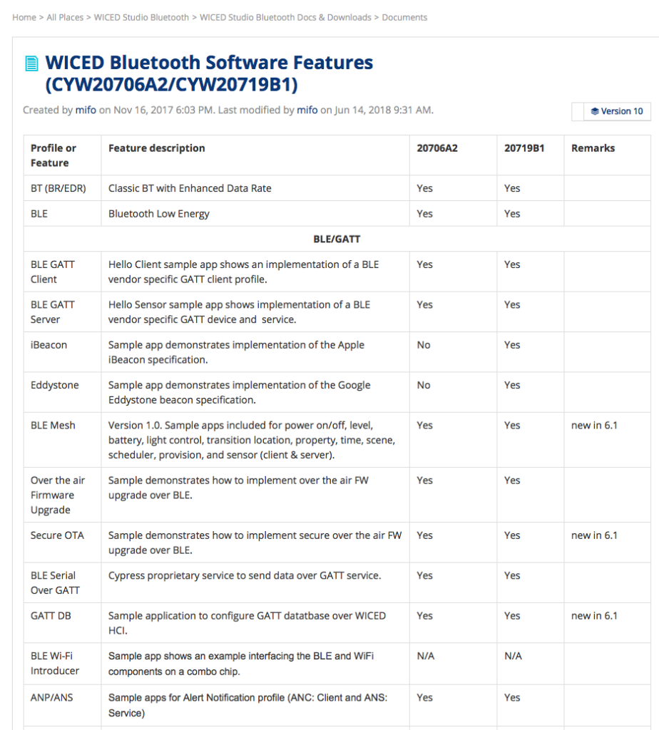
CYW20719 Software Features

This webpage has a list of all of the stuff that you have access to inside of the WICED Bluetooth SDK.

And it goes on and on and on from here.

WICED Module Selection Guide

If you feel like building a Bluetooth Product, you are almost certainly going to want to use a FCC certified module.  This guide is a discussion of all of the module vendors.

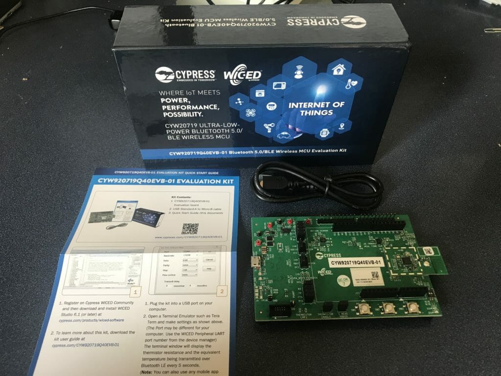
CYW920719Q40EVB-01 Development Kit

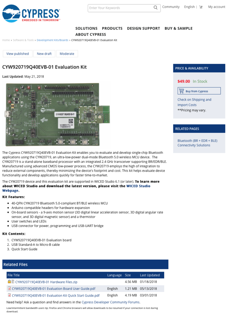
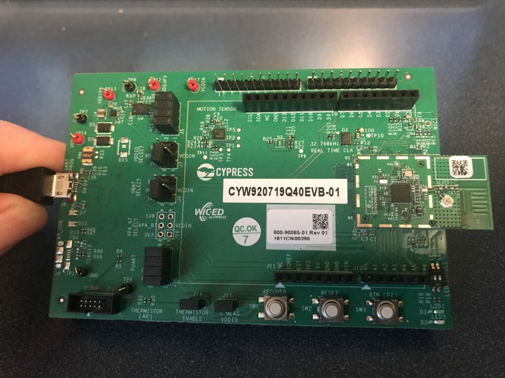
Here is the development kit.  You can see in the picture that this is an Arduino form factor board.  It has a button and and LED plus programmer and UART bridge.  Most importantly it has a daughter card with the 20719 and and antenna.

CYW920719Q40EVB-01 Product Page

The product landing pages for the development kit has lots of resources specific to this kit including the manual and quick start guide.

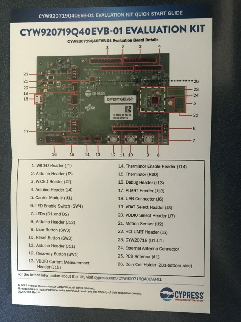
CYW920719 Quick Start

The Quickstart guide is included in the kit.  Just a single sheet of paper that points out all of the features of the development kit.

CYW920719Q40EVB-01 Evaluation Board User Guide

The Users Guide is the manual for the development kit.  It shows you how to use all of the resouces on the board and how to get going with WICED Studio.

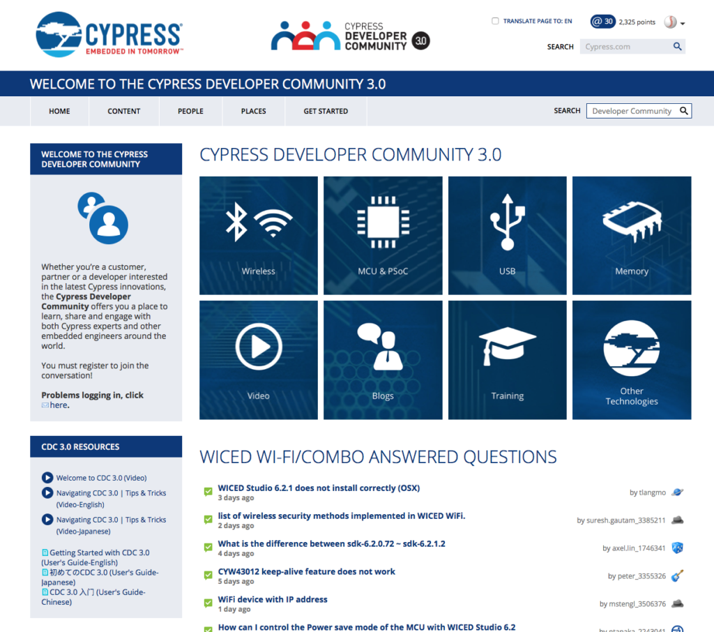
Cypress Community

The community is your anchor for support.  It has all of the documentation etc… and most importantly a vibrant user forum.

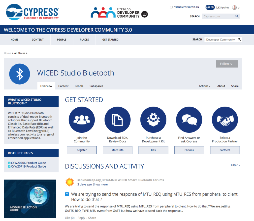
WICED Studio Bluetooth Community

The Bluetooth Community website brings together all of the people and product collateral for WICED Bluetooth.

WICED Studio Bluetooth Forums

The actual forum is accessible to everyone to ask questions about the Cypress products.  It is staffed by our technical support team and you will get good answers.

WICED Studio

WICED Studio is the development tool which you can use to build projects.  This will be the central tool used for the rest of this class.

WICED Studio Bluetooth Example Projects

Cypress delivers a bunch of “apps” which range from small examples we call SNIPs to more fully featured projects (in the Demo) folder.  Ill be showing you how to use the in the next set of tutorials.

WICED Studio Documentation

In the “doc” folder resides all of the documentation for WICED bluetooth.

WICED Bluetooth API Guide

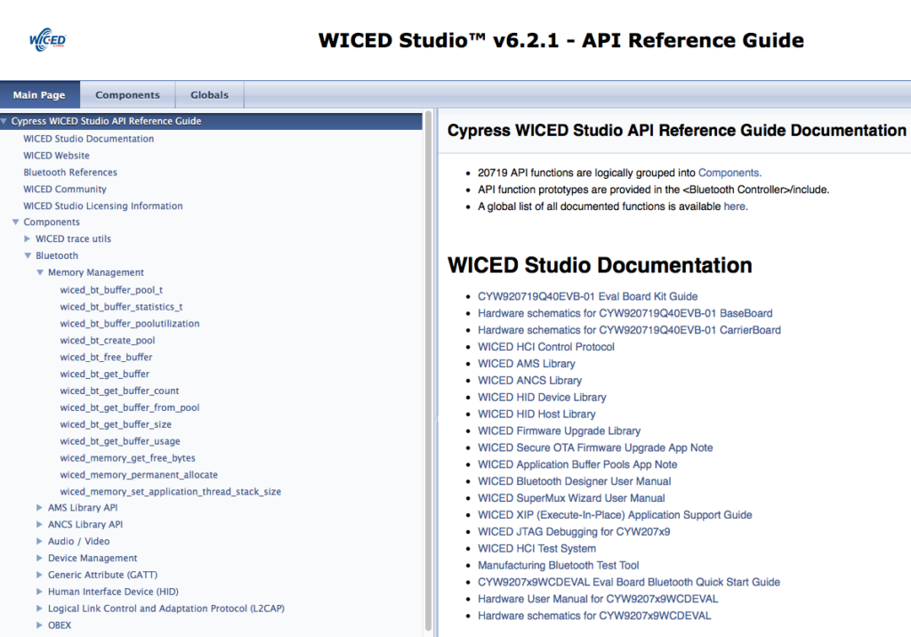
The API guide is doxygen generated API documentation for the WICED Bluetooth SDK.

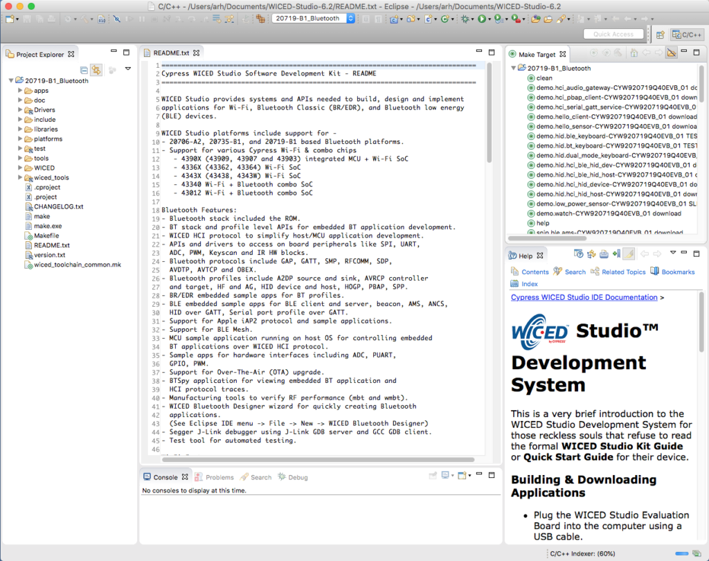
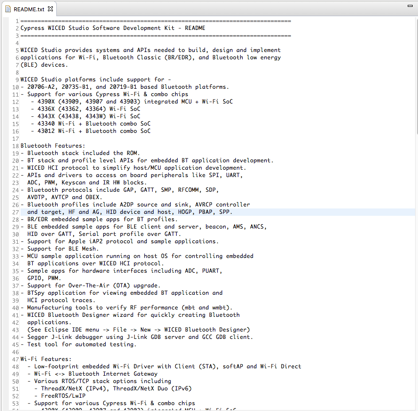
WICED Studio README.txt

WICED Studio Release Notes


WICED Studio Technical Brief

WICED Bluetooth 101

I have been working with  some amazing people to build a class for learning WICED Bluetooth.  You can find all of the material at https://github.com/cypresssemiconductorco/CypressAcademy_WBT101_Files

Lesson 0 – A Two Hour WICED Bluetooth Class

Summary

This is the top level web page for a two hour class about getting you started building products with WICED Bluetooth using the CYW20719.  My friend Victor told me that I am totally insane and that I have enough material for a semester long class, but I have faith in you.  The whole point of WICED Bluetooth is to make it possible for you to build your own Bluetooth application using the best Bluetooth radios in the world.  Life is too short for flaky Bluetooth!

When I started working on this class the marketing guys asked if they could show a “few” powerpoint slides at the begining.  But I knew that is just a euphemism for power point carpet bombing you to sleep.  That sucks, so we aren’t doing that.

AFH, TDD, ∏/4 DQPSK, ISM, 8DPSK, Symbol Rate, binary FM modulation, dBi, LMP, AMP, Gaussian Frequency Shift Keying,  Modulation Index, ppm, eye diagram, FCC, Frequency Offset, Slot Length, Frequency Drift, Differential Phase Encoding, Pulse Shaping, Modulation Accuracy, Differential Error Vector Magnitude, BER, Sensitivity, Co-Chanel interference, Intermodulation Characteristics, Symbol rate, Timeslot, piconet clock, piconet channel timing,  blah blah blah blah….

Whew… now that is out of the way.  Forget that.  Rather than start at the bottom with the radio and Maxwells equations I going to start at the top.  Cypress has a huge team of radio designers to deal with all of that so you don’t have to.  To be clear, this stuff matter A LOT to how well your product works but it is only the second best reason to use Cypress WICED Bluetooth.  The best reason to use Cypress is that our software team lets you have access to the most robust Bluetooth stack and radio infrastructure without having to figure all that crap out.  You may, in time, dig into all of that.  But none of it matters for building your applications.

This workshop is hands on, as that is the only real way to learn.  This series of web pages have the exact steps that I am going to use, so you can follow along with me.

You will need a few things for the class:

  • WICED Studio 6.2.1 which you can download from the Cypress Community
  • Copies of the example projects which you can get from GitHub.
  • A CYW920719Q40EVB-01 which you can get from Mouser
  • A Terminal Program like Putty
  • CySmart, a Bluetooth GATT DB Browser for Android (Google Play Store) or iPhone (Apple App Store)
  • The courage to be WICED!

Todays virtual workshop is going to go like this:

WICED Bluetooth Using the CYW20719

# Title Comment
0 A Two Hour WICED Bluetooth Class WICED Bluetooth Using the CYW20719 in all its glory
1 Resources Links to all of the Cypress WICED information including videos, application notes etc.
2 Your First Project Making Hello World & the Blinky LED
3 The Super Mux Tool Learning about platforms and the Super Mux Tool
4 Snips Using the example projects to learn Bluetooth
5 Bluetooth Designer Using the tool to customize a project and get going fast
6 The CCCD & Notification Writing back to the Central
7 Advertising  Beacon Building a beacon project to advertise your custom information 
8 Scanner Viewing the world around you
9 Bluetooth Classic SPP Using the Serial Port Profile to Transmit Lots of Data

Source code: 

  • git@github.com:iotexpert/wiced_bt_intro.git
  • https://github.com/iotexpert/wiced_bt_intro


WICED Studio 6.2.1

This class is build around WICED Studio 6.2, the Cypress IDE built on top of Eclipse.  WICED Studio has all of the tools, examples and SDKs to build projects for the Cypress WICED Bluetooth and WiFi products.  We support Windows, Mac and Linux and you can download it from our community website: https://community.cypress.com/community/wireless (which I hope you have done by now)

CYW920719Q40EVB-01

I am going to build and program all of the projects in this class into our development kit, the CY920719Q40EVB-01.  This development kit (which you should buy from Mouser) uses the Cypress CYW20719 Bluetooth chip.  This is the worlds best Dual-mode Bluetooth 5.0 chip.  Dual mode means that it does Bluetooth Classic BR/EDR as well as Bluetooth Low Energy.  Even better it can do both standards at the same time.

PSoC 6 BLE – Find Me Profile (Target)

Summary

I have been working on making some new videos for Cypress about the PSoC 6 BLE.  Everyone always likes to start with an easy BLE example, and the go to example is the “Find Me”.  I started by building a Find Me Profile example, but when I looked my example I decided that I wanted to trace the actual application all the way back to the Bluetooth Special Interest Group (SIG) specification.  So, that is exactly what I do for this article.

  • Bluetooth SIG Find Me Profile
  • Bluetooth SIG Immediate Alert Service
  • Configure PSoC 6 BLE Schematic & Pins
  • Setup FreeRTOS and Retarget I/O
  • PSoC 6 BLE Firmware Architecture
  • Firmware for the alertTask
  • Firmware for the Immediate Alert Service Callback
  • Firmware for the BLE Callback
  • Firmware for the BLE Task
  • Firmware to start the system

Bluetooth SIG Find Me Profile

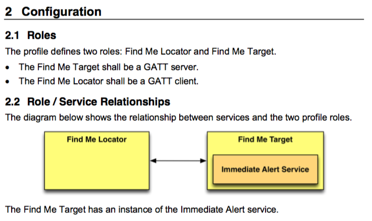
The Bluetooth SIG defines a bunch of standard profiles.  A standard Profile is just some combination of standardized Services and Characteristics.  One of those Profiles is the Find Me Profile.  The concept behind the Find Me Profile was that you could connect to a device with the Find Me Profile, and then send it an alert, at which point it would start “alerting” (presumably blinking or beeping).  You could imagine a tag attached to your car keys for instance.  You can get the Find Me Profile Specification from the Bluetooth SIG website.  The spec is a 10ish page pdf that says a Find Me Profile is just a device with an Immediate Alert Service server or client.  Here is a picture from the spec:

The other interesting part of the specification defines how the advertising is supposed to work

Immediate Alert Service

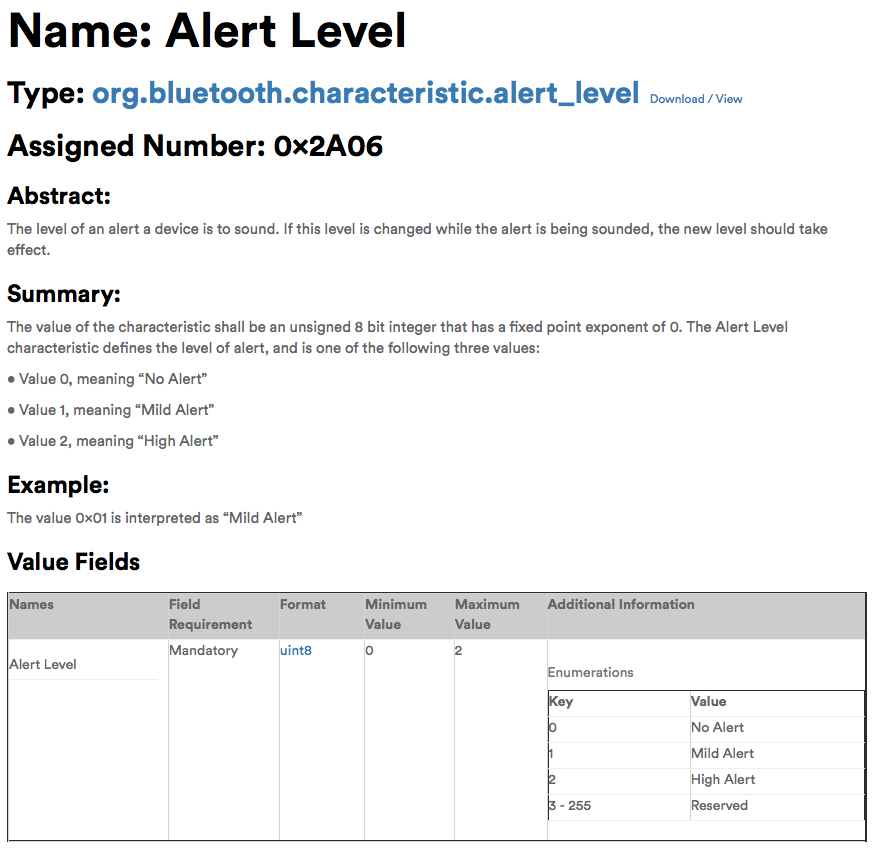
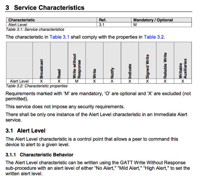
But, what is an Immediate Alert Service?  Well, you can get the Immediate Alert Service specification from the Bluetooth SIG website as well.  It basically says that there is one Service called Immediate Alert with a UUID of 0x1802 and that Service has one Characteristic called “Alert Level” with a UUID of 0x2A06. Here is a screen shot.

Unfortunately the spec doesnt have the UUIDs in it, and you have to follow the [1] to the website.  On the Bluetooth SIG GATT Services UUID definition webpage you can see the UUID of the Immediate Alert Service (0x1802)

And on the Bluetooth SIG GATT Characteristics definition webpage you can see the UUID of the Alert Level (0x2A06)

It also says the alert characteristic is writable with three values (No, Mild, High) and if you click on Alert Level you can see the definition of those:

Next you can see information about the Alert Characteristic.

Configure PSoC 6 BLE Schematic & Pins

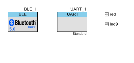
Now, lets build the project.  Create a new PSoC 6 BLE project and edit the schematic to have a BLE, UART, and two digital output pins (red, led9).

Assign the pins to the correct place on the CY8CKIT-062-BLE development kit.  I am going to use led9 to show when the device is connected (or not)

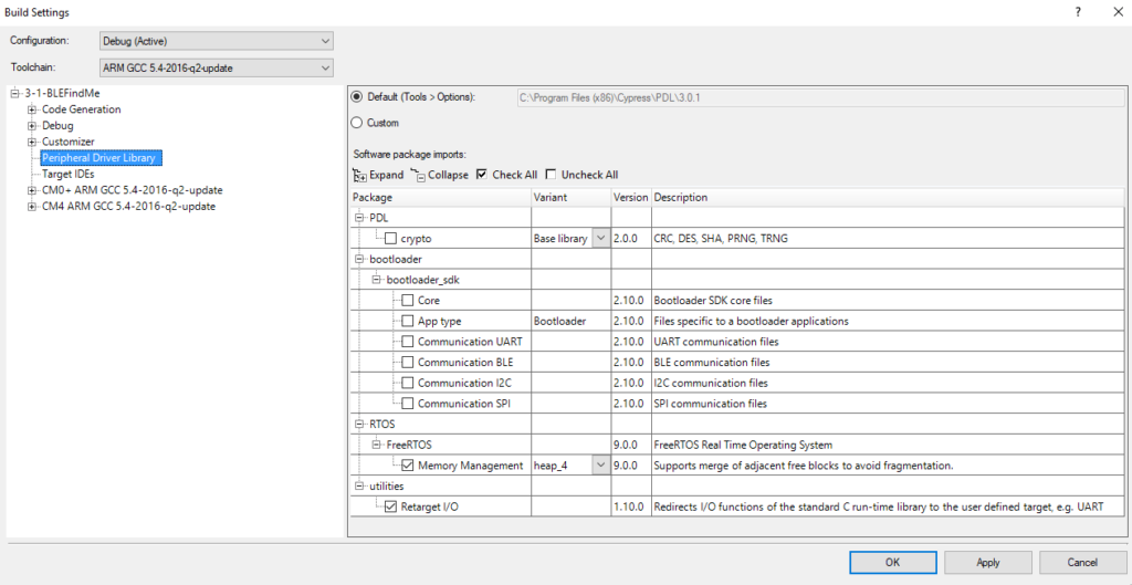
Change the build settings to add FreeRTOS (Heap 4) and Retarget I/O

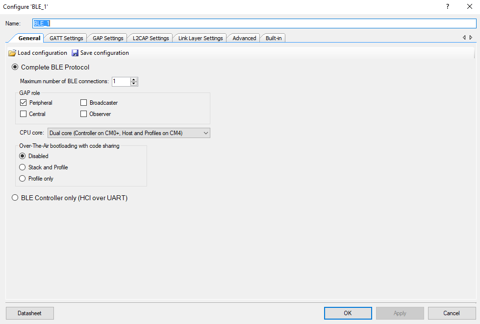
Configure the BLE to be dual core and a peripheral

Add the Find Me Target (GATT Server) profile

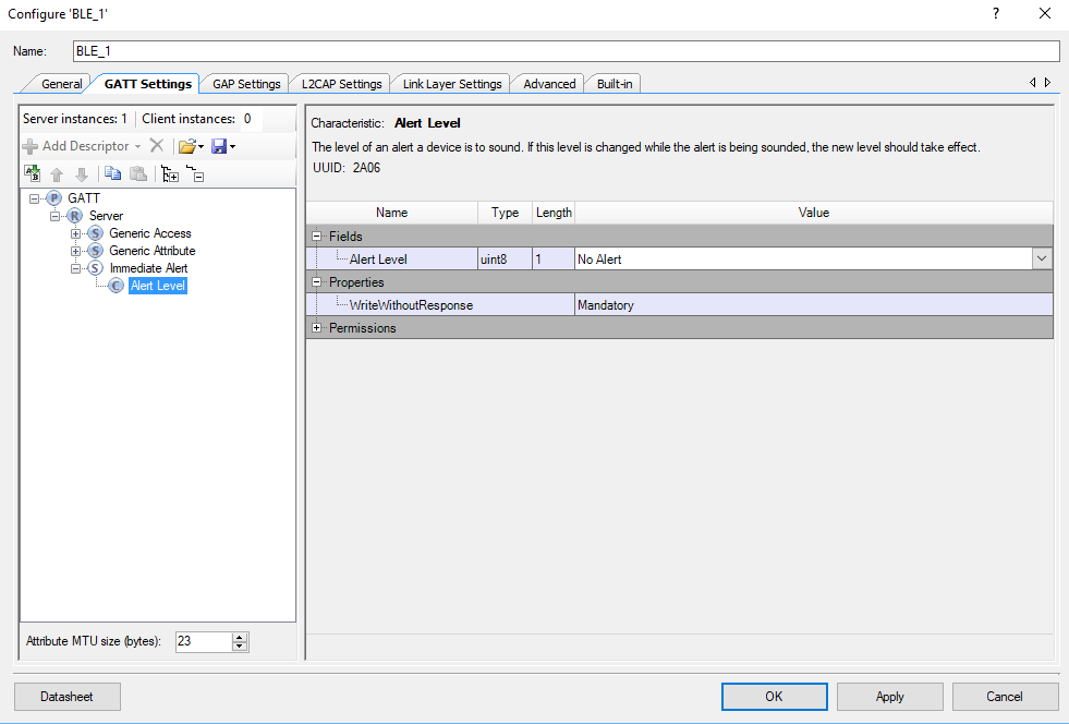
Once that is done you will see the Immediate Alert Service (with the correct UUID from above)

And the Alert Level with the correct UUID

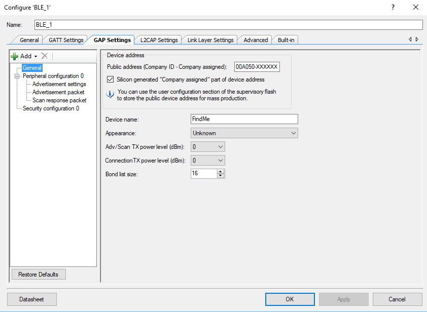
Next give the device a name (“FindMe”)

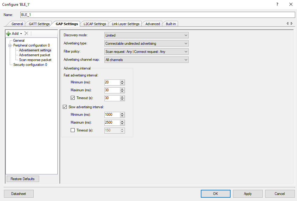
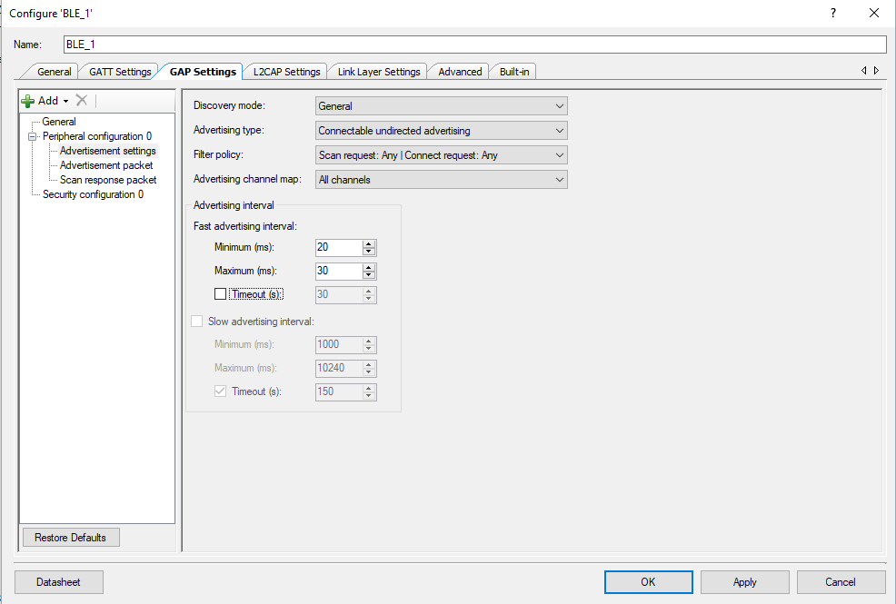
The spec calls for the advertising setup to be as follows

But I have to admit that I dont like to wait… so I configured it like this:

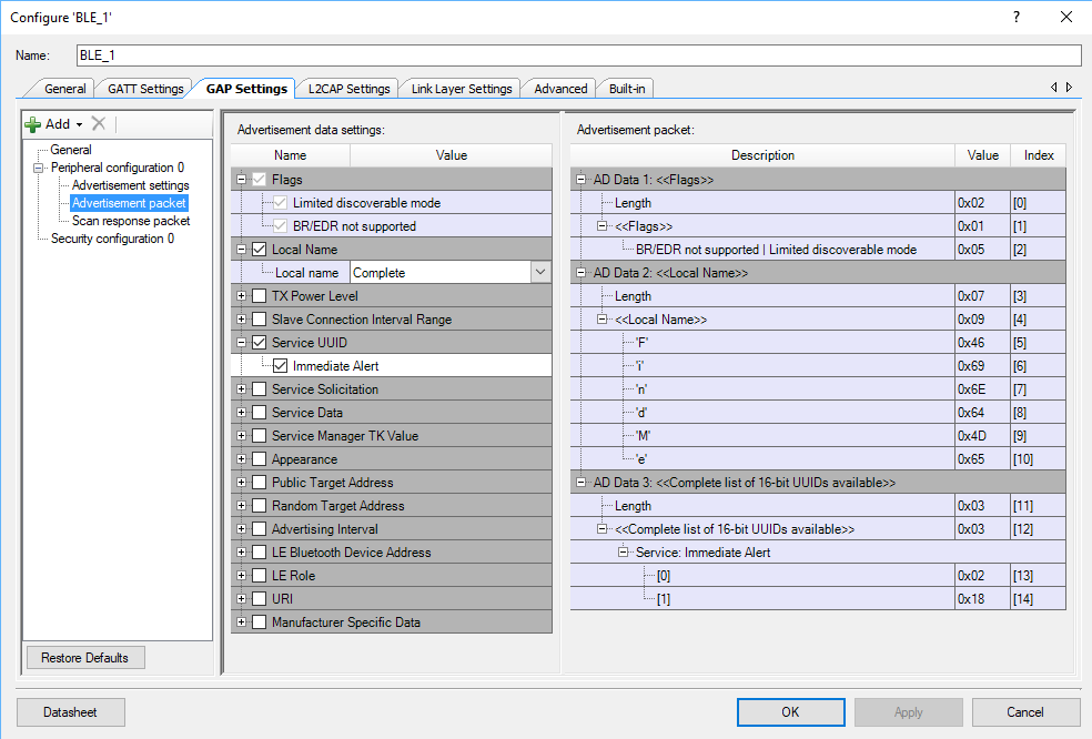
Next, configure the advertising packet to have the name of the device and the fact that it has a IAS Service

Setup FreeRTOS and Retarget I/O

Run “Generate Application” to bring in all of the BLE and PDL firmware.  Then edit “stdio_user.h” to setup the stdio support.

#include "project.h"
/* Must remain uncommented to use this utility */
#define IO_STDOUT_ENABLE
#define IO_STDIN_ENABLE
#define IO_STDOUT_UART      UART_1_HW
#define IO_STDIN_UART       UART_1_HW

Next, modify FreeRTOSConfig.h to include support for semaphores.

#define configUSE_COUNTING_SEMAPHORES           1

and a much bigger stack

#define configTOTAL_HEAP_SIZE                   (48*1024)

And finally the interrupts to support BLE

/* Put KERNEL_INTERRUPT_PRIORITY in top __NVIC_PRIO_BITS bits of CM4 register */
#define configKERNEL_INTERRUPT_PRIORITY         0xFF
/* Put MAX_SYSCALL_INTERRUPT_PRIORITY in top __NVIC_PRIO_BITS bits of CM4 register */
//#define configMAX_SYSCALL_INTERRUPT_PRIORITY    0xBF
#ifdef __NVIC_PRIO_BITS
/* __BVIC_PRIO_BITS will be specified when CMSIS is being used. */
#define configPRIO_BITS                   __NVIC_PRIO_BITS
#else
#define configPRIO_BITS                   4        /* 15 priority levels */
#endif    
#define configMAX_SYSCALL_INTERRUPT_PRIORITY    ( 1 << (8 - configPRIO_BITS) )

Firmware Architecture

There will be two tasks

  1. The alertTask which will be responsible for setting the state of the red LED.  To set the state of the LED any other task can set the EventGroup bits.
  2. The bleTask which will handle running the BLE and the generic BLE callback and the IAS callback.

Firmware for the alertTask

The alert task will

  1. Set things up including eventBits which I call “alertState”
  2. Turn off the red led
  3. Go into an infinite loop
  4. The loop will either 1) wait until the end of time or 2) timeout at 500ms)
  5. Then it will determine the cause of the timeout and set the state of the red LED
// These BITs are used to set the state of the red LED
EventGroupHandle_t alertState;
#define ALERT_NO_MASK   1<<0
#define ALERT_MILD_MASK 1<<1
#define ALERT_HIGH_MASK 1<<2
/*****************************************************************************\
* Function:    alertTask
* Input:       FreeRTOS Template - unused argument
* Returns:     void
* Description: 
*     This funtion is the mainloop for the alertTask.  It manages the state of
*     the RED led.  Other tasks communitcate with this task using the alertState
*     event bits.
\*****************************************************************************/
void alertTask(void *arg)
{
(void)arg;
printf("Alert Task Started\r\n");
TickType_t delay=portMAX_DELAY;
EventBits_t currentBits;
alertState = xEventGroupCreate();
xEventGroupSetBits(alertState,ALERT_NO_MASK);
Cy_GPIO_Write(red_PORT,red_NUM,LED_OFF);
while(1)
{
currentBits = xEventGroupWaitBits(alertState,ALERT_HIGH_MASK|ALERT_MILD_MASK|ALERT_NO_MASK,
pdTRUE,pdFALSE,delay);
switch(currentBits)
{
case ALERT_NO_MASK:
delay = portMAX_DELAY;
Cy_GPIO_Write(red_PORT,red_NUM,LED_OFF);
break;
case ALERT_HIGH_MASK:
delay = portMAX_DELAY;
Cy_GPIO_Write(red_PORT,red_NUM,LED_ON);
break;
case 0: // case 0 means timer expired & no bits set.   
case ALERT_MILD_MASK:
delay = 500;
Cy_GPIO_Inv(red_PORT,red_NUM);
break;
}   
}
}
Firmware for the Immediate Alert Service Callback

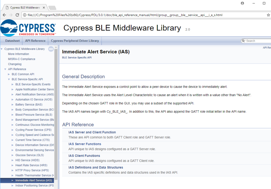
Cypress setup a bunch of APIs that know how to handle a bunch of the Bluetooth SIG Profiles/Services.  First lets look at the PSoC 6 BLE Middleware PDL Documentation to find the IAS Service.  It is in the “BLE Service-Specific API” section.

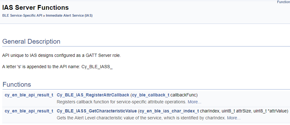
We want to implement a “GATT Server”… meaning our device has the IAS Server running on it so that a GATT Client can write into our database.  When I click on “IAS Server Functions” it takes me to this section of the documentation.  Basically what you do in your firmware is

  1. Register a callback with Cy_BLE_IAS_RegisterAttrCallback
  2. Setup the function that will be called back when the Alert Level characteristic is written.

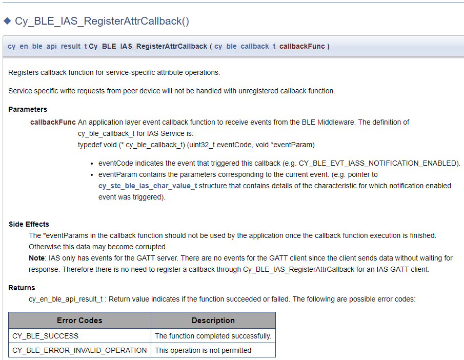
Here is the documentation for the callback.  You can see that you need to make a function that matches the prototype of “cy_ble_callback_t”)

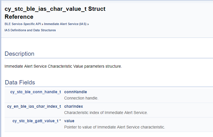
When you are called back you will get a void * which you can then cast into a pointer of type “cy_stc_ble_ias_char_value_t *”.  This structure will contain the value of the alert in the “cy_stc_ble_gatt_value_t *value” member.

If you look at the “cy_stc_ble_Gatt_value_t” structure you will find that it contains a pointer to an array of uint8_t (actually one one)

Now to actually write the callback function.  It just:

  1. Looks and sees if it is a write callback
  2. finds the value using the “Cy_BLE_IASS_GetCharacteristicValue” function.
  3. Then sends a message to the alertTask
/*****************************************************************************\
* Function:    iasCallback
* Input:       BLE IAS Service Handler Function: 
*      - eventCode (which only can be CY_BLE_EVT_IASS_WRITE_CHAR_CMD
*      - eventParam which is a pointer to  (and unused)
* Returns:     void
* Description: 
*   This is called back by the BLE stack when there is a write to the IAS
*   service.  This only occurs when the GATT Client Writes a new value
*   for the alert.  The function figures out the state of the alert then
*   sends a message to the alertTask usign the EventGroup alterState
\*****************************************************************************/
void iasCallback(uint32_t eventCode, void *eventParam)
{
(void)eventParam;
uint8_t alertLevel;
if(eventCode == CY_BLE_EVT_IASS_WRITE_CHAR_CMD)
{
/* Read the updated Alert Level value from the GATT database */
Cy_BLE_IASS_GetCharacteristicValue(CY_BLE_IAS_ALERT_LEVEL, 
sizeof(alertLevel), &alertLevel);
// The value of the characteristic could also be gotten like this:
//switch(((cy_stc_ble_ias_char_value_t *)eventParam)->value->val[0])
switch(alertLevel)
{
case CY_BLE_NO_ALERT:
printf("No alert\n");
xEventGroupSetBits(alertState,ALERT_NO_MASK);               
break;
case CY_BLE_MILD_ALERT:
printf("Medium alert\n");
xEventGroupSetBits(alertState,ALERT_MILD_MASK);               
break;
case CY_BLE_HIGH_ALERT:        
printf("High alert\n");
xEventGroupSetBits(alertState,ALERT_HIGH_MASK);               
break;
}   
}   
}
Instead of calling the function to get the values, you could have also been done this:

switch(((cy_stc_ble_ias_char_value_t *)eventParam)->value->val[0])

Firmware for the Ble Event Handler

The BLE event handler is really simple,  it just prints out some debugging information depending on the event.  It also starts the advertising when the stack starts or when it has been disconnected.

/*****************************************************************************\
* Function:    customEventHandler
* Input:       Cy_BLE Event Handler event and eventParameter
* Returns:     void
* Description: 
*   This funtion is the BLE Event Handler function.  It is called by the BLE
*   stack when an event occurs 
\*****************************************************************************/
void customEventHandler(uint32_t event, void *eventParameter)
{
(void)eventParameter; // not used
switch (event)
{
case CY_BLE_EVT_STACK_ON:
printf("Stack Started\r\n");
Cy_BLE_GAPP_StartAdvertisement(CY_BLE_ADVERTISING_FAST, CY_BLE_PERIPHERAL_CONFIGURATION_0_INDEX);
break;
case CY_BLE_EVT_GAP_DEVICE_DISCONNECTED:
printf("Disconnected\r\n");
Cy_GPIO_Write(led9_PORT,led9_NUM,LED_OFF); // Turn the LED9 Off
Cy_BLE_GAPP_StartAdvertisement(CY_BLE_ADVERTISING_FAST, CY_BLE_PERIPHERAL_CONFIGURATION_0_INDEX);
break;
case CY_BLE_EVT_GATT_CONNECT_IND:
printf("Connected\r\n");
Cy_GPIO_Write(led9_PORT,led9_NUM,LED_ON); // Turn the LED9 On             
break;
default:
break;
}
}
Firmware for the bleTask

The bleTask has two functions

  1. an ISR that is called whenever an IPC event happens (so that it can unlock the semaphore to process events)
  2. a main function which starts the system, registers the callback and runs process events at the right time.
/*****************************************************************************\
* Function:    bleInterruptNotify
* Input:       void (it is called inside of the ISR)
* Returns:     void
* Description: 
*   This is called back in the BLE ISR when an event has occured and needs to
*   be processed.  It will then set/give the sempahore to tell the BLE task to
*   process events.
\*****************************************************************************/
void bleInterruptNotify()
{
BaseType_t xHigherPriorityTaskWoken;
xHigherPriorityTaskWoken = pdFALSE;
xSemaphoreGiveFromISR(bleSemaphore, &xHigherPriorityTaskWoken); 
portYIELD_FROM_ISR( xHigherPriorityTaskWoken );
}
/*****************************************************************************\
* Function:    bleTask
* Input:       A FreeRTOS Task - void * that is unused
* Returns:     void
* Description: 
*  This task starts the BLE stack... and processes events when the bleSempahore
*  is set by the ISR.
\*****************************************************************************/
void bleTask(void *arg)
{
(void)arg;
printf("BLE Task Started\n");
bleSemaphore = xSemaphoreCreateCounting(UINT_MAX,0);
Cy_BLE_Start(customEventHandler);
Cy_BLE_IPC_RegisterAppHostCallback(bleInterruptNotify);
while(Cy_BLE_GetState() != CY_BLE_STATE_ON) // Get the stack going
{
Cy_BLE_ProcessEvents();
}
Cy_BLE_IAS_RegisterAttrCallback (iasCallback);
for(;;)
{
xSemaphoreTake(bleSemaphore,portMAX_DELAY);
Cy_BLE_ProcessEvents();
}
}
Main Firmware

Finally the main firmware just starts all of the tasks.

// Starts the system
int main(void)
{
__enable_irq(); 
UART_1_Start();
setvbuf( stdin, NULL, _IONBF, 0 ); 
setvbuf( stdout, NULL, _IONBF, 0 ); 
printf("System Started\r\n");
xTaskCreate(bleTask,"bleTask",8*1024,0,2,&bleTaskHandle);
xTaskCreate(alertTask,"AlertTask",configMINIMAL_STACK_SIZE,0,1,0);
vTaskStartScheduler();
for(;;)
{
}
}
Test

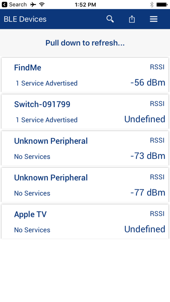
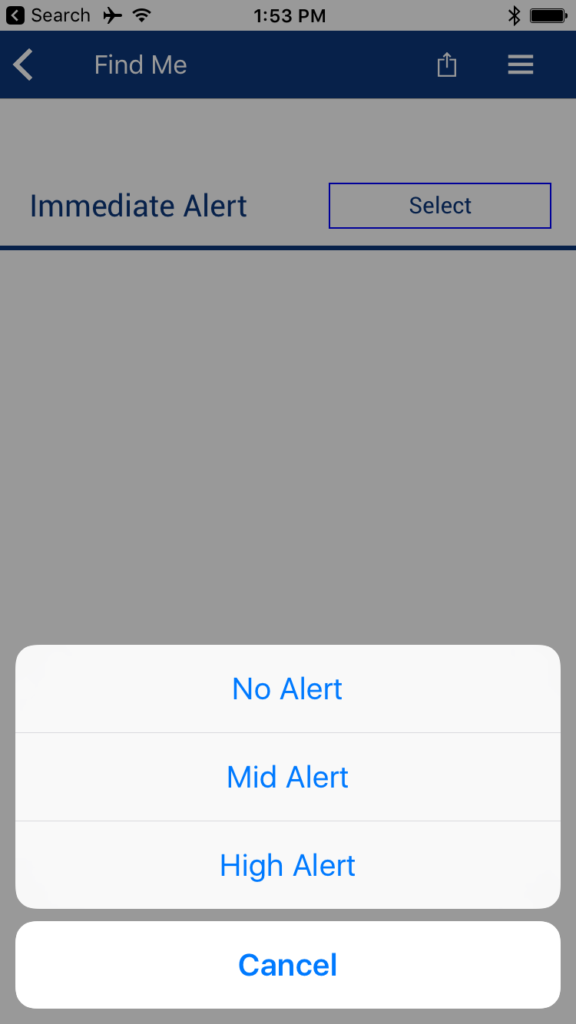
After doing all of this, you can run CySmart to test the system:


PSoC4 BLE Central – Using the CySmart Dongle

Summary

In the previous article I showed you how to build PSoC4 BLE Central firmware to talk to a BLE Peripheral.  When I did that firmware I built it to program into a CY8CKIT-042-BLE kit.  What I should have done was made the firmware work with the CySmart Dongle.  An error that I will fix in this article.

In this article I give you an introduction to the CySmart dongle, then I will show you how to:

  • Update the firmware on the dongle (both KitProg and the PRoC)
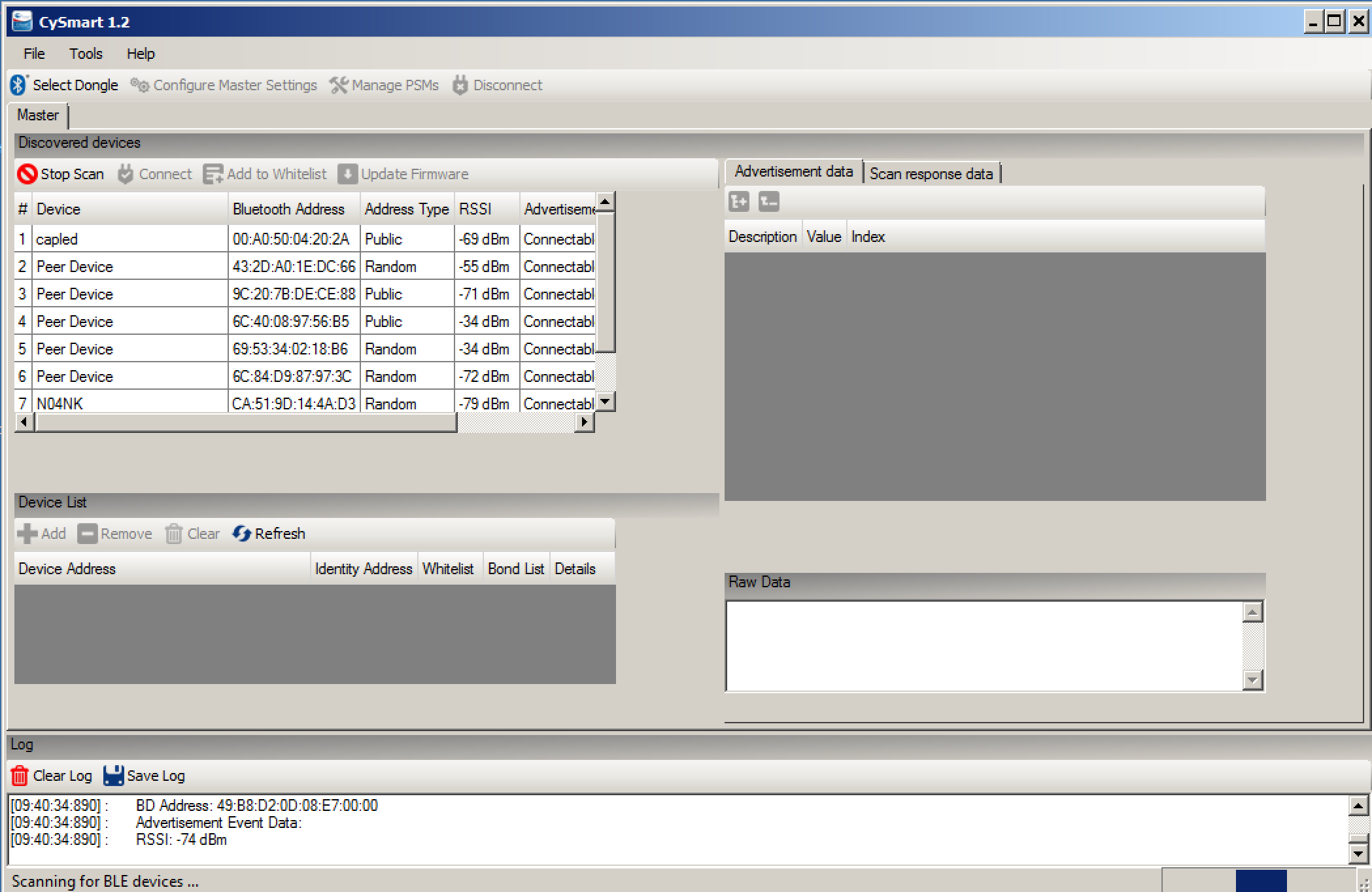
  • Use the PC to debug a PSoC4 BLE Peripheral
  • Modify the PSoC4 BLE Central Project to work on the CySmart Dongle

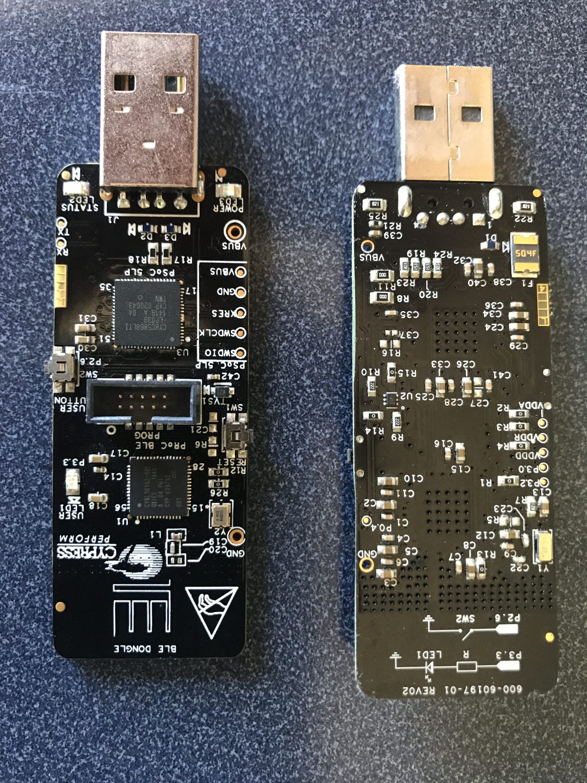
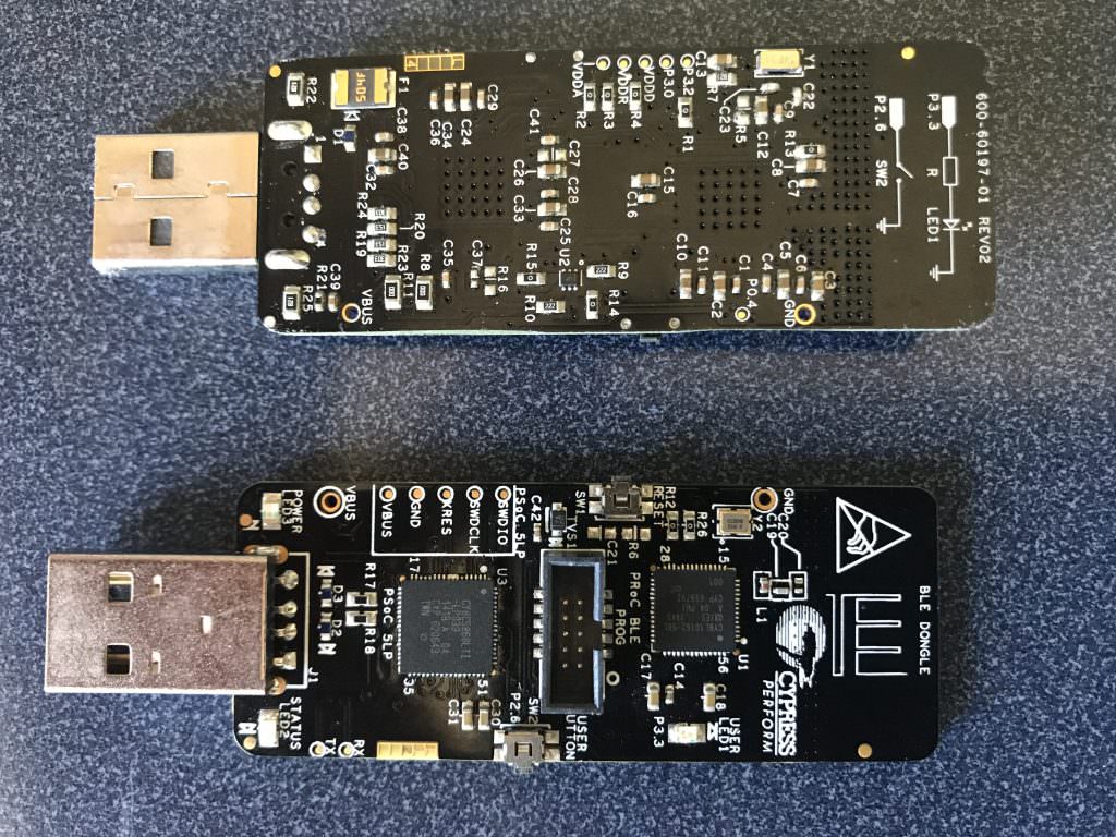
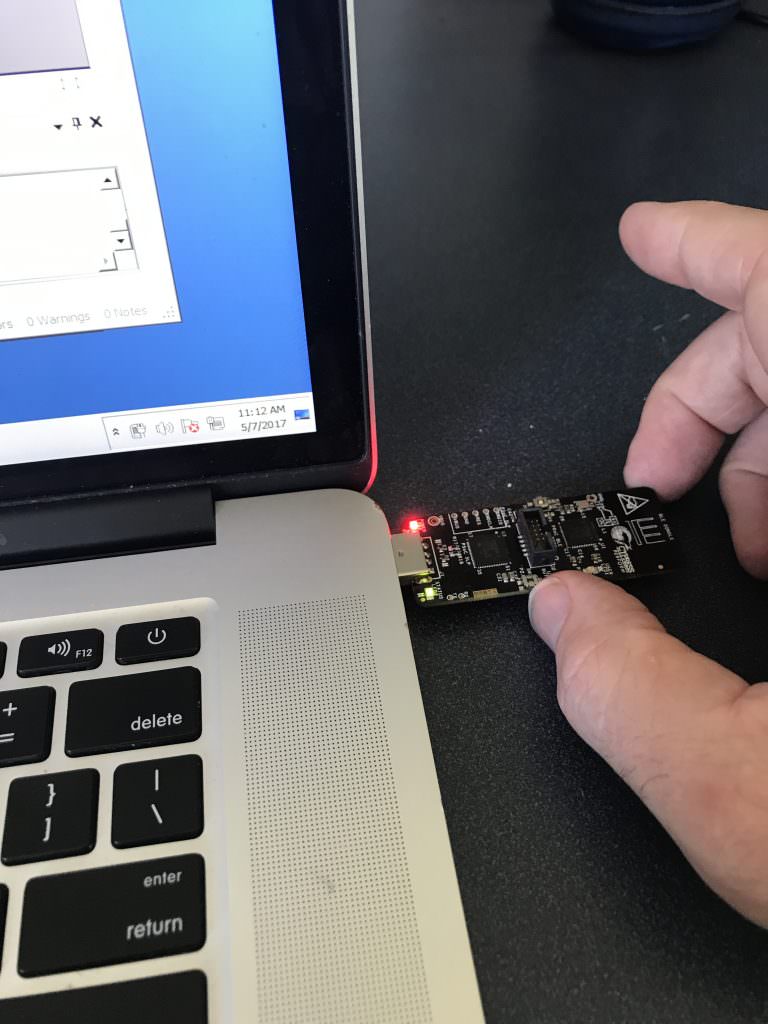
CySmart Dongle

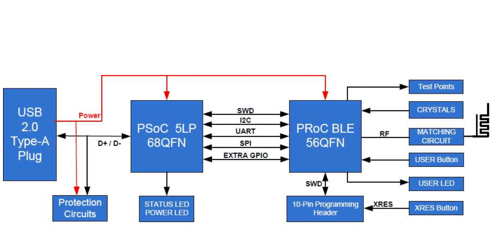
As you can see in the picture above, the CySmart dongle is a USB dongle with a PRoC BLE Radio on it.  It uses a PSoC5 programmed with the KitProg firmware to bridge from the PRoC to the PC.  In the diagram below you can see that it can bridge SWD, I2C, UART and SPI.  In addition the dongle has 1 user button and 1 user LED.  This is perfect for the PSoC4 BLE CapSense LED GAP Central Project that I built in the previous article.

You get the CySmart dongle as part of the CY8CKIT-042-BLE Kit.  The dongle comes programmed with the CySmart Firmware which enables you to connect to the CySmart PC Program (more later in this article).

There are two version of the dongle

  • CY5670 with PRoC & 128K of Flash
  • CY5671 with PRoC & 256K of Flash

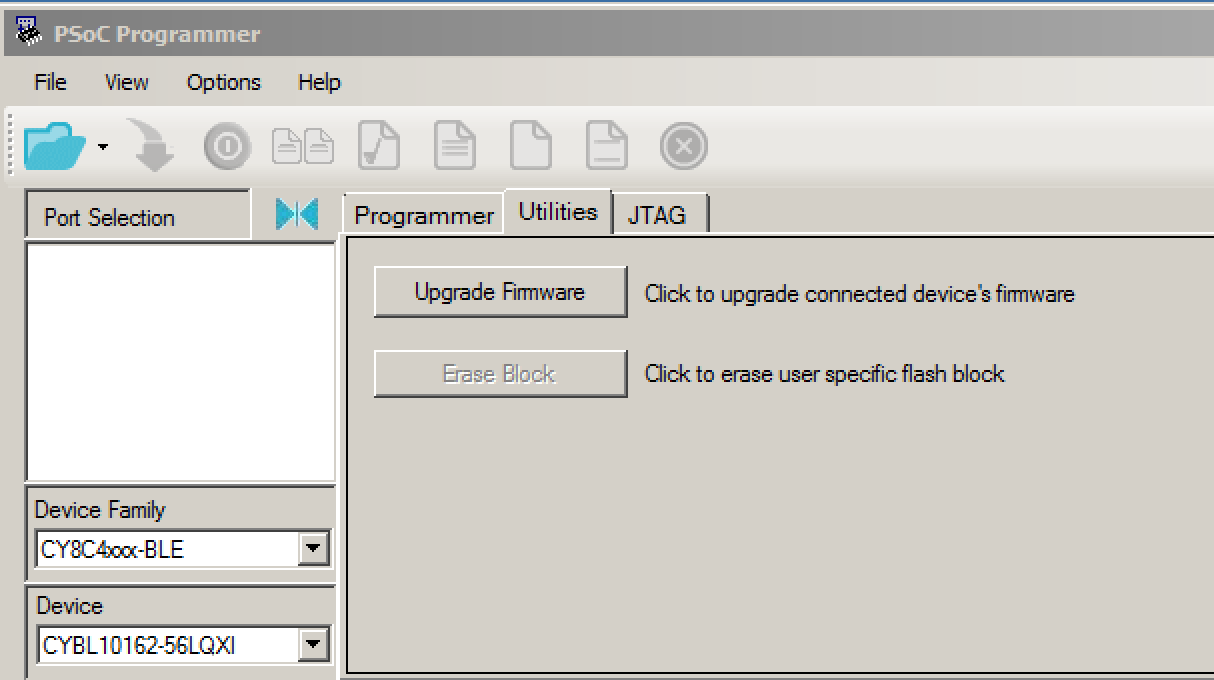
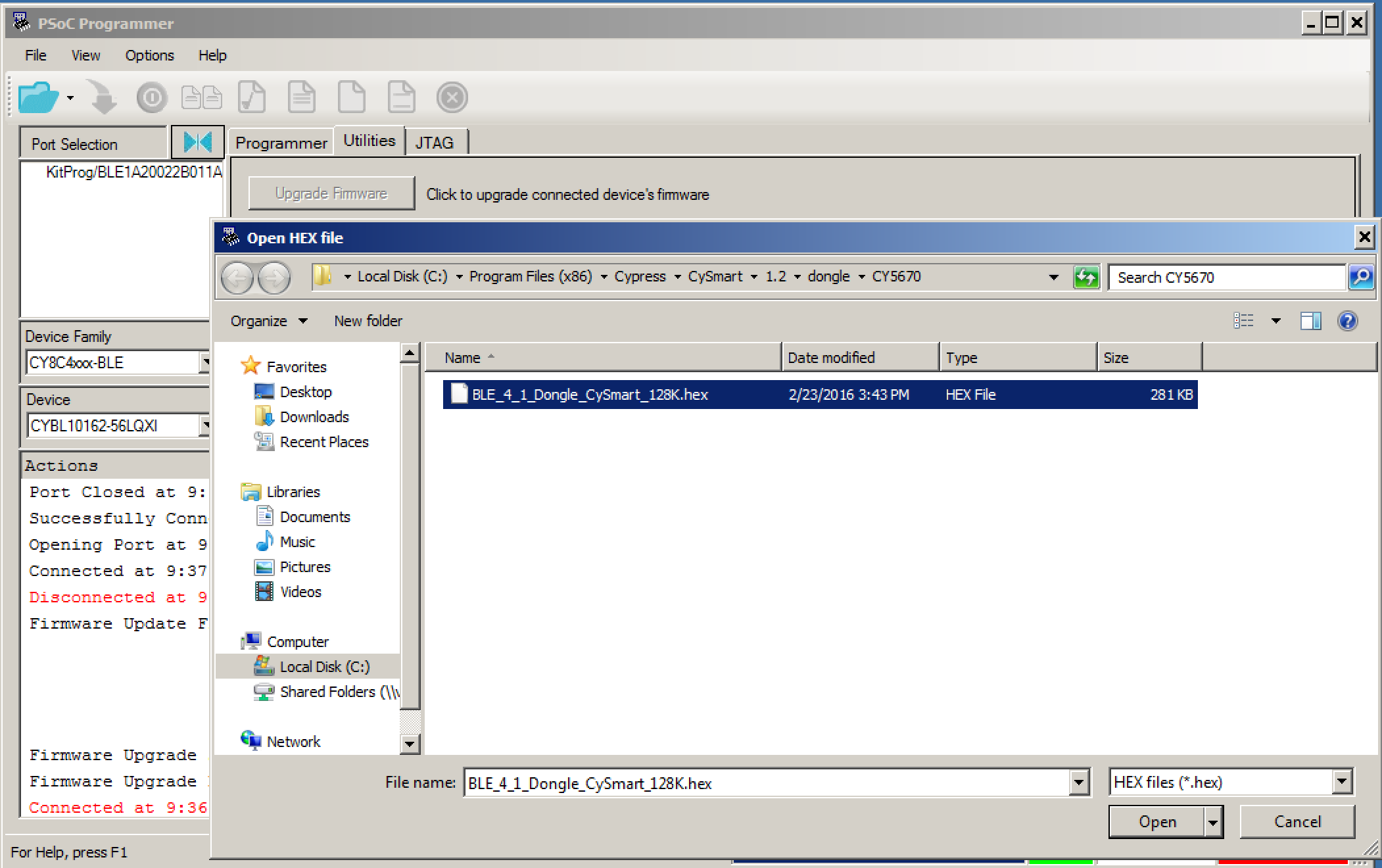
Update the CySmart Dongle

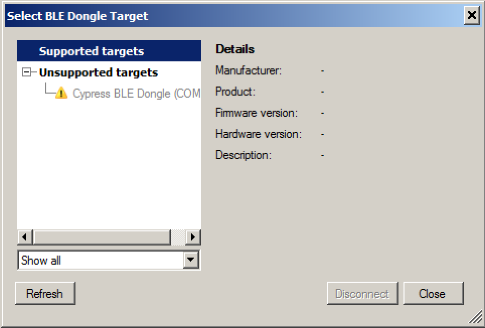
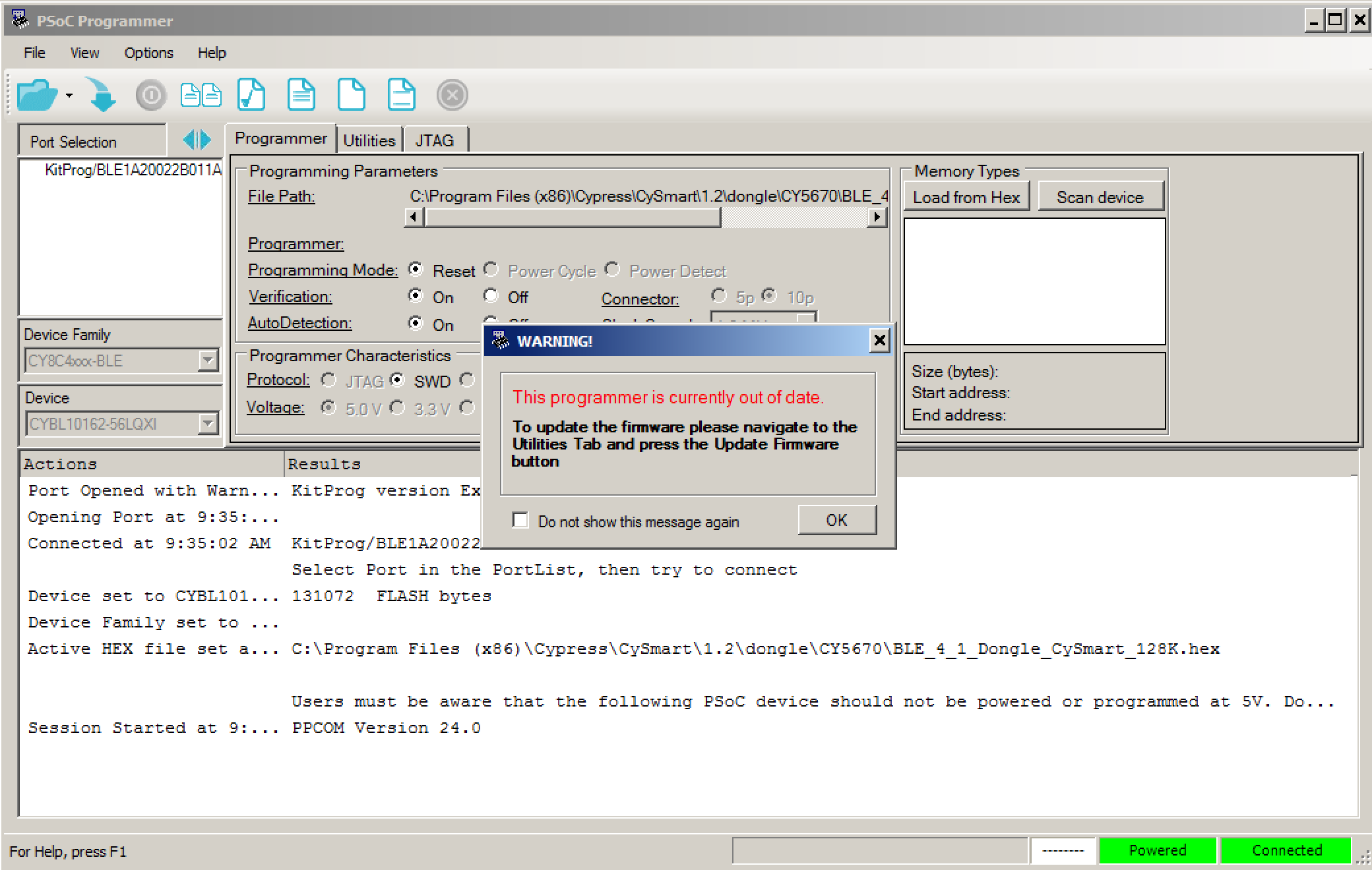
Literally (well almost) every time I plug in a CySmart dongle, I get this message telling me that it is an “Unsupported Target”.  This means that the  firmware is out of date and needs to be updated.

In order to fix the firmware, you need to quit the CySmart program, then start the PSoC Programmer software.  And, I also find that every time I start PSoC Programmer that the KitProg firmware is out of date.  To fix this press OK.

Then click the “Utilities” tab, then “Upgrade Firmware”

Once the KitProg firmware is up to date, you can then program the CySmart firmware.  Press the “folder” button, then navigate to the firmware which lives in Program Files(x86) –> CySmart –> 1.2 –> dongle –> CY5670.  Then press the “down arrow” which means “download the firmware”.  Once that is done, you are good to go with running CySmart (quit PSoC programmer so that it can talk to the dongle).

Use the PC CySmart to Debug a PSoC4 BLE Peripheral

Now that I have a functional CySmart dongle, I can run CySmart.  This is a Windows PC Version of a GATT browser (like the CySmart iOS/Android App or the LightBlue app that I used in the previous article).  In CySmart press “Start Scan”.  In the picture below you can see all of the BLE peripherals that CySmart can see, including the “capled” project.

Once I click on “capled” and then “connect” and finally “discover all attributes” I will get a window that looks like this.  You can see all of the GATT Database.

After that I can Read and Write attributes (like the LED Attribute) by typing the value I want to write into the box on the upper right, and pressing “Write Value”.  For example you can turn on the LED by writing a “1” into the LED characteristic.
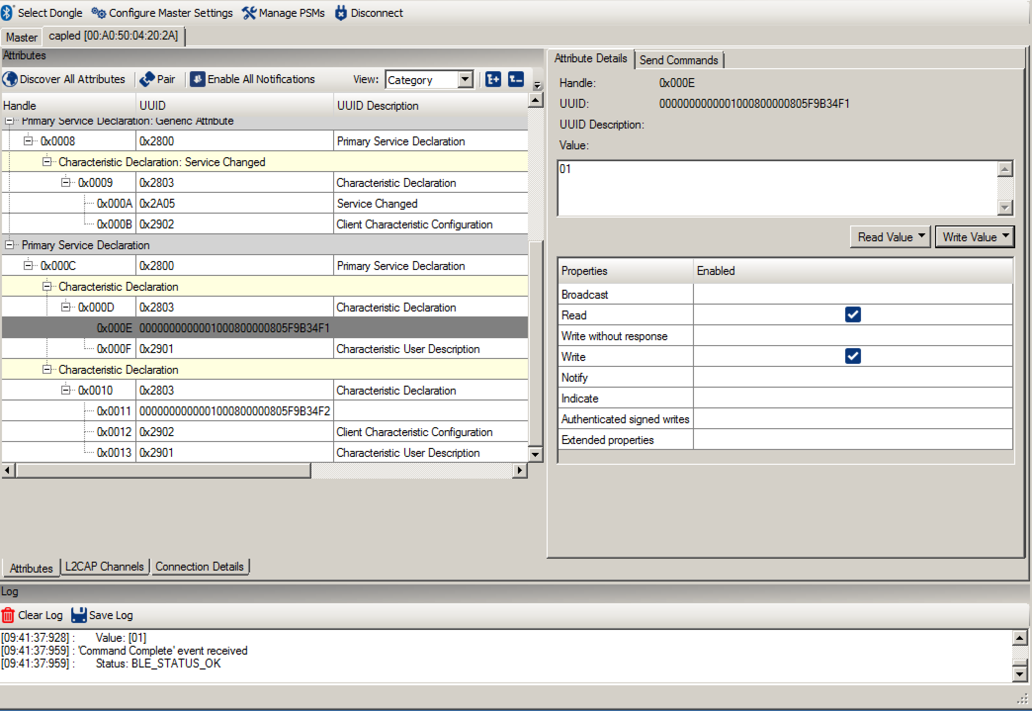
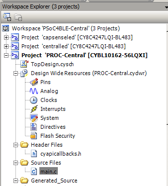
Modify the PSoC4 BLE Central Project to work on the CySmart Dongle

Next, lets modify the original project so that it can work on the dongle.  I will start this whole process by doing a copy/paste of the “centralled” project.  Then renaming it to “PROC-Central”

The dongle has a PRoC instead of a PSoC4 BLE.  This means you need to run the device selector and change the target device.  I can never remember which version of PROC is on the dongle.  So, to figure it out I click the program button, which brings up this screen that says my project isn’t compatible with the target.  It also tells me that this dongle has “CYBL10162-56LQXI”

Now go to “Project –> Device Selector” and change to the “CYBLE10162-56LQXI”

The pin assignments are a little bit different.  On the back of the board you can see that we put a handy-dandy picture showing the arrangement for the LED and the button.

But unfortunately we didn’t show you the pins for the UART on the silkscreen.  But you can find those in the schematic (which can be downloaded from the website)

Now you can assign the correct pins (noticed that I deleted the red/blue LED pins because they don’t exist on the dongle)

Finally you need to change the PWM to be active high instead of active low.

Now program and test it.  The user switch is the tiny little button under my thumb.

CySmart Dongle Testing BLE Central

As with the previous article you can find all of this source code on the IoT Expert Github site or git@github.com:iotexpert/PSoC4BLE-Central.git.  In the next article I will start the process of building a GATT Browser inside of a PSoC4 BLE.

PSoC4 BLE Central Custom Profile w/LED & CapSense

Summary

Last week I got a nice email from a Cypress customer in Italy (I think).  He asked about implementing a PSoC4 BLE Central.  I replied that it was pretty easy.  Over the weekend I thought about it a little bit more and realized that I had never implemented the Central a.k.a. the “other” side of a BLE connection in a PSoC.  I had always built the Central side in an iPhone application written in Swift or Android application written in Java.  So it seemed like a good thing to do to implement it in C.  It turned out to not be quite as easy I had hoped because of some problems in the Cypress documentation.  In the next several articles I am going to show you how to implement a PSoC4 BLE Central.

I am going to use the project from the video series called “capsenseled” as the GAP Peripheral and then I am going to show you how to write the GAP Central code.  You can learn about the GAP Peripherals in the video series called “PSoC® 4 BLE 101 Video Tutorial Series: How To Create Products Using PSoC 4 BLE“.  Here is the first video from YouTube.

In that series of videos I showed you how to build a custom GATT profile for Capsense and an LED.  The GAP Peripheral has an LED that you can control from the GAP Central, and it has a Capsense slider that you can read its value from the GAP Central.  You can “git” all of the source for this project from the IoTExpert Github website or git@github.com:iotexpert/PSoC4BLE-Central.git

In this article I will show you:

  • The GAP Peripheral and GATT Database
  • How to build the schematic for the GAP Central
  • How to configure the BLE component for the GAP Central functionality
  • The steps required in the firmware to read and write the GAP Peripheral

The GAP Peripheral and GATT Database

To start the process I will “git” the source code for this GAP Peripheral from the IOT Expert Github site.  Then, I open the project called “capsenseled” in PSoC Creator.  The schematic has:

  • The Capsense component which controls the slider
  • A PWM that drives the blue LED to serve as a notification of the state of the BLE (blinking means advertising)
  • A red LED which can be turned on/off from the GAP Central Side
  • The BLE Component

PSoC4 BLE CapSense LED Peripheral

The BLE Component is configured to be:

  • A GAP Peripheral
  • with a GATT Server

PSoC4 BLE Peripheral Configuration

The GATT Database is setup to have:

  • A custom service called “ledcapsense”
  • A custom characteristic called “led” (a uint8)
  • A custom characteristic called “capsense” (a uint16)

PSoC4 BLE Peripheral GATT Configuration

The advertising packet is setup to advertise

  • The name of the device “capled”
  • The fact that it has a GATT Service called “ledcapsense”

PSoC4 BLE Peripheral Advertising Packet

When you program this project you will get a blinking blue LED (that says the BLE is advertising).  When I run “lightblue” I can see the “capled” advertising:
LightBlue BLE Explorer

After I connect the device I can see the UUID of the custom service & the two characteristics:

LightBlue BLE Explorer

Finally I can read/write the led characteristic.

LightBlue BLE Explorer

PSoC4 BLE Central Schematic

To make my PSoC4 BLE Central I build a project for the CY8CKIT-042-BLE  (you can see all of the source code in the project called “centralled”

CY8CKIT-042-BLE

Start by building a schematic with

  • A debug UART (I will print to the terminal program)
  • The red/blue/green led pins
  • The mechanical button pin (called SW1)
  • A PWM to drive the green LED (it will vary the brightness of the LED based on the capsense value on the GAP Peripheral)
  • The BLE Component

PSoC4 BLE Central Schematic

Configure the PWM (to vary between 0 and 100% brightness) with inverted logic (because the LED on the board is active low)

PSoC4 BLE Central PWM

Assign the Pins:

PSoC4 BLE Central Pin Assignment

You will need to configure the BLE to be a:

  • A GATT Client
  • A GAP Central

PSoC4 BLE Central BLE Configuration

If you tell the BLE Component what the GATT Server configuration looks like (on the GAP Peripheral side) it will make the service discovery firmware much simpler.  To do this, go to the GAP Peripheral project and export the “ledcapsense” service from the Peripheral into an xml file (see the Save Selected Service…)

PSoC4 BLE Central GATT Database

Then go back to your PSoC4 BLE Central project and add a new service “From file” (see at the bottom of the menu)

PSoC4 BLE Central - Load Service

After all that you will end up with something that looks like this.  You can see the “ledcapsense” service is listed under the “client” section of the GATT configuration.

PSoC4 BLE Central GATT Database

PSoC4 BLE Central Firmware

The firmware for the PSoC4 BLE Central needs to:

  1. Initialize the PSoC
  2. Scan for GAP Peripherals that are advertising the “ledcapsense” service
  3. Connect to the GAP Peripheral & Discover its services
  4. Turn on notifications for the Capsense characteristic
  5. Loop
    1. If the users changes the state of the button then send over a LED on/off
    2. If you receive a notification of a change in capsense then update the PWM Compare value (to change the intensity)

Most of the Cypress BLE APIs will create an “event” that you will need to process in the BLE loop.  The interesting events are:

Event Description
CYBLE_EVT_STACK_ON The BLE Stack has turned on and you can start advertising
CYBLE_EVT_GAP_DEVICE_DISCONNECTED The GAP Peripheral you were attached to has disconnected.  Start scanning for another GAP Peripheral to attach to
CYBLE_EVT_GAP_DEVICE_CONNECTED You have successfully completed a connection to a GAP Peripheral
CYBLE_EVT_GAPC_SCAN_PROGRESS_RESULT You received an advertising packet from a GAP Peripheral
CYBLE_EVT_GAPC_SCAN_START_STOP You either stopped or started scanning for advertising packets from GAP Peripherals
CYBLE_EVT_GATT_CONNECT_IND The GATT Connection is complete.  This event occurs before the CYBLE_EVT_GAP_DEVICE_CONNECTED EVENT so you don't need to do anything
CYBLE_EVT_GATTC_DISCOVERY_COMPLETE The service discovery is complete.  You can now set the CCCD and turn on the PWM
CYBLE_EVT_GATTC_HANDLE_VALUE_NTF You received a notification of a change in the Capsense from the GAP Peripheral.
CYBLE_EVT_GATTC_WRITE_RSP: Your write succeeded.  For this application there is nothing to do

To make all of this work, I created a state machine using an enumerated datatype.

// Modes for a statemachine
typedef enum SystemMode {
SM_INITIALIZE,          // Startup state
SM_SCANNING,            // Looking for a Peripheral
SM_CONNECTING,          // I have issued connected and waiting for it to complete
SM_SERVICEDISCOVERY,    // Started the service discovery and waiting for it to complete
SM_CONNECTED            // Connection complete... 
} SystemMode_t;
static SystemMode_t systemMode = SM_INITIALIZE; // Starting mode of statemachine

1. Initialize the PSoC4 BLE Central

The project starts with the normal turn on the PSoC components and stuff.

int main(void)
{
CyGlobalIntEnable; /* Enable global interrupts. */
UART_Start();
PWM_Start();
CyBle_Start( CyBle_AppCallback );

2. Scan for Peripherals that are advertising the “ledcapsense” service

Most everything that happens in the BLE sub-system triggers a callback to your “AppCallback” which you registered when you started up the BLE component.  The AppCallback has two parameters, which event and a generic void* style argument which can be one of a bunch of things.

(Lines 73-79)  After you turn on the power to your central and the BLE subsystem you will need to start scanning for peripherals that are advertising.  To do this you call “CyBle_GapcStartScan”.  The “Gapc” part of the API name means GAP Central.  The other time you need to start scanning is when you have been disconnected.

(Lines 81-93)  When you receive an advertising packet you can look in the packet and figure out if it is a GAP Peripheral that you want to attach too.  In this case I:

  • Only look at packets that are 29 bytes long (which I looked up in the BLE GAP Peripheral project)
  • And.. if the packet has the UUID of the capsenseled service
  • Then I save the Bluetooth Device Address (BD address) and stop scanning.  When the scanning is stopped the BLE subsystem will issue and event called “CYBLE_EVT_GAPC_SCAN_START_STOP” (the next section)
       case CYBLE_EVT_STACK_ON:
case CYBLE_EVT_GAP_DEVICE_DISCONNECTED:
systemMode = SM_SCANNING;
enabledCapsenseNotifications = 0;
CyBle_GapcStartScan(CYBLE_SCANNING_FAST); // Start scanning for peripherals
PWM_WriteCompare(0); PWM_Stop();          // Turn off the LED
break;
CYBLE_GAPC_ADV_REPORT_T* scanReport;
case CYBLE_EVT_GAPC_SCAN_PROGRESS_RESULT:                     // Advertising packet
scanReport = (CYBLE_GAPC_ADV_REPORT_T*)eventParam;
if(scanReport->dataLen != 29)                             // Number of bytes in ledcapsense advertising packet
break;
if(memcmp(&CapLedService,&scanReport->data[11],sizeof(CapLedService))) // if service is in packet
return;
// Setup for the connection
remoteDevice.type = scanReport->peerAddrType;          // setup the BD addr
memcpy(&remoteDevice.bdAddr,scanReport->peerBdAddr,6); // 6 bytes in BD addr
systemMode = SM_CONNECTING;
CyBle_GapcStopScan();                                  // stop scanning for peripherals
break;


3. Connect to the Peripheral & Discover the Services

(lines 97-100) When the BLE either starts or stops scanning it issues the “CYBLE_EVT_GAPC_SCAN_START_STOP” event.  I use the state machine to determine what to do.  Basically if the mode of my system is “SM_CONNECTING” then I attempt to make a connection to the remote device.

(lines 102-105)  Once the device is connected you need to do a service discovery to find out what services are on the GAP Peripheral and more importantly what are the handles of the characteristics.  The CyBle_GattcStartDiscovery issues requests to the GAP Peripheral to tell the services and characteristics on the peripheral, to which it responds with events.  Cypress provides code in BLE_custom.h and BLE_custom.c to process those responses.  Once the discovery is complete you are then ready to talk to the device.

        case CYBLE_EVT_GAPC_SCAN_START_STOP: // If you stopped scanning to make a connection.. then launch connection
if(systemMode == SM_CONNECTING ) 
CyBle_GapcConnectDevice(&remoteDevice);
break;
case CYBLE_EVT_GAP_DEVICE_CONNECTED:              // Connection request is complete
CyBle_GattcStartDiscovery(cyBle_connHandle);  // Discover the services on the GATT Server
systemMode = SM_SERVICEDISCOVERY;
break;

4. Turn on notifications for the Capsense characteristic

We are interested in getting notified when the Capsense characteristic on the GAP Peripheral changes.  To enable getting a notification you need to write a “0x01” into the Client Characteristic Configuration Descriptor or CCCD.  In order to accomplish this you need to know the handle of that descriptor.  The handle is discovered automatically by the BLE_custom.c functions.  If you look in BLE_custom.h you will find #define(s) that are the indexes of the things you need to know from the service discovery array.

/* Below are the indexes and handles of the defined Custom Services and their characteristics */
#define CYBLE_CUSTOMC_LEDCAPSENSE_SERVICE_INDEX   (0x00u) /* Index of ledcapsense service in the cyBle_customCServ array */
#define CYBLE_CUSTOMC_LEDCAPSENSE_LED_CHAR_INDEX   (0x00u) /* Index of led characteristic */
#define CYBLE_CUSTOMC_LEDCAPSENSE_LED_CHARACTERISTIC_USER_DESCRIPTION_DESC_INDEX   (0x00u) /* Index of Characteristic User Description descriptor */
#define CYBLE_CUSTOMC_LEDCAPSENSE_CAPSENSE_CHAR_INDEX   (0x01u) /* Index of capsense characteristic */
#define CYBLE_CUSTOMC_LEDCAPSENSE_CAPSENSE_CAPSENSECCCD_DESC_INDEX   (0x00u) /* Index of capsensecccd descriptor */
#define CYBLE_CUSTOMC_LEDCAPSENSE_CAPSENSE_CHARACTERISTIC_USER_DESCRIPTION_DESC_INDEX   (0x01u) /* Index of Characteristic User Description descriptor */

To set the CCCD you create a “CYBLE_GATTC_WRITE_REQ_T” and fill it in with the information required.  Specifically, the value and the handle which you find on line 57.  Then you write it to the GAP Peripheral.

/***************************************************************
* Function to set the Capsense CCCD to get notifications
**************************************************************/
void updateCapsenseNotification()
{
CYBLE_GATTC_WRITE_REQ_T 	tempHandle;
uint8 cccd=1;  
enabledCapsenseNotifications = 1;
tempHandle.attrHandle = cyBle_customCServ[CYBLE_CUSTOMC_LEDCAPSENSE_SERVICE_INDEX]
.customServChar[CYBLE_CUSTOMC_LEDCAPSENSE_CAPSENSE_CHAR_INDEX]
.customServCharDesc[CYBLE_CUSTOMC_LEDCAPSENSE_CAPSENSE_CAPSENSECCCD_DESC_INDEX].descHandle;
tempHandle.value.val = (uint8 *) &cccd;
tempHandle.value.len = 1;
CyBle_GattcWriteCharacteristicValue(cyBle_connHandle,&tempHandle);
}

5. Main Loop

The main look is simple.  Basically if you are in the SM_CONNECTED state, then call the function which updates the state of the Remote LED.

   for(;;)
{ 
switch(systemMode)
{
case SM_INITIALIZE:
case SM_SCANNING:
case SM_CONNECTING:
case SM_SERVICEDISCOVERY:
break;
case SM_CONNECTED:
updateLed();
break;
}
CyBle_ProcessEvents();
CyBle_EnterLPM(CYBLE_BLESS_DEEPSLEEP);    
}
}


5. Main Loop (Write the state of the LED)

This function looks at the state of the switch, then if it has changed, sends the updates state to the Peripheral.  The switch is active low (a 0 means that it is pressed) but we want a “1” to mean turn on the LED.

Just like the updateCapsenseNotification() function, you look in the cycle_customCServ array to find the handle of the LED characteristic.
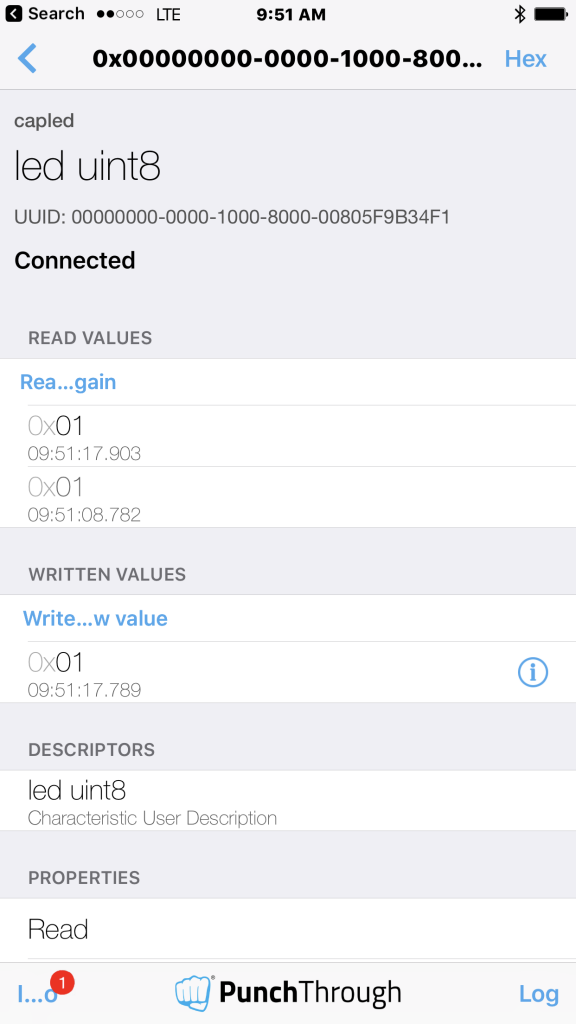
/***************************************************************
* Function to update the LED state in the GATT database
* Based on state of swtich
**************************************************************/
void updateLed()
{
static int previousState = 10;       // The first time it is called send the data
uint8 state;                         // A place to hold the state of the switch
CYBLE_GATTC_WRITE_REQ_T tempHandle;  // A handle to call the BLE API
state = !SW1_Read();                 // Active low switch
if(state == previousState)           // If nothing has changed dont send anythign
return;
previousState = state;
tempHandle.attrHandle = cyBle_customCServ[CYBLE_CUSTOMC_LEDCAPSENSE_SERVICE_INDEX]
.customServChar[CYBLE_CUSTOMC_LEDCAPSENSE_LED_CHAR_INDEX]
.customServCharHandle;
tempHandle.value.val = (uint8 *) &state;
tempHandle.value.len = 1;
CyBle_GattcWriteCharacteristicValue(cyBle_connHandle,&tempHandle);
}

5. Main Loop (Capsense Notifications)

The last bit of code updates the state of the PWM driving the LED when you get a notification from the GAP Peripheral that it has been updated.

        CYBLE_GATTC_HANDLE_VALUE_NTF_PARAM_T *capsenseNTF;    
case CYBLE_EVT_GATTC_HANDLE_VALUE_NTF:                                 // Capsense Notification Recevied
capsenseNTF = (CYBLE_GATTC_HANDLE_VALUE_NTF_PARAM_T *)eventParam;
if(capsenseNTF->handleValPair.value.val[0] == 0xFF)                // Turn off the LED in no touch
PWM_WriteCompare(0);
else
PWM_WriteCompare(capsenseNTF->handleValPair.value.val[0]);
break;
case CYBLE_EVT_GATTC_WRITE_RSP: // Sucesfull write - nothing to do
break;

In the next Article(s) I will show you how to use the CySmart dongle.  I am also planning on showing you the firmware to create a GATT Browser.

You can find all of the source code for these projects at github.com/iotexpert/PSoc4BLE-Central 

WICED WiFI

Last week I had the supreme privilege of hosting the WICED WiFI + Bluetooth + Zigbee software team at my office in Kentucky. This included the overall manager for WICED software (a truly remarkable guy), the engineering managers for WiFI and Bluetooth, the head of applications for WICED as well as a bunch of the firmware guys.  It occurred to me during the week that the people joining Cypress was the best part of the Broadcomm IOT acquisition.  And that is saying something as I really like the products.  Also at the summit were all of the software engineering leaders for PSoC (who I have worked with closely all of my career).  Needless to say, it was a bunch of badass developers.

The purpose of the meeting was to introduce the PSoC team to WICED and then talk about the future roadmap for those products.  Obviously I can’t talk to much about the 2nd part… well actually the only thing I can say is that it will be amazing as we will be able to offer PSoC with the power of WICED.

What I can talk about is the first part.  So, I thought that I would show you one of the things that we did with WICED.  First of all, WICED (Wireless Internet Connectivity for Embedded Devices) is the brand name that Cypress uses to describe all of the WiFi, Zigbee and Bluetooth chips and modules that were acquired from Broadcom/Avago.  The other thing we call WICED is the WICED SDK which is used to mean Eclipse plus all of the tools (programer, plugins etc) plus the software library that is used to build products using the WICED chips and modules.

In the world of programming the first example is always “hello world”.  In the world of MCUs the first example is always “blinking led”.  It turns out that the first example in WiFi is “scan” to show that you can see all of the WiFi networks around you.   The purpose of all of these examples is to prove that all of the tools can do their thing.

To start with they gave me this devkit, the BCM94343WWCD1_1  IMG_3049

The first thing to do is install WICED 3.7.  When you start WICED you will see a screen like this:

Screen Shot 2016-08-22 at 8.22.06 AM

For the purposes of the first design there are two important things to see on this screen.  First on the left side is the project explorer.  It has all of the guts of WICED.  As part of the installation we provide you a bunch of “apps”.  These apps range from simple examples (in the snip folder) to full fledged production quality applications (in the demo folder)

  • demo – full fledged applications
  • snip – short example projects
  • test – tools for debugging and testing wifi
  • waf – WICED Application Framework support (like an OTA Bootloader)
  • wwd – low level driver examples

Screen Shot 2016-08-22 at 8.27.04 AM

The example that I want to build is “scan”  specifically “scan.c”.  That can be found in the apps/snip/scan folder.  In this screenshot you can see that I opened “scan.c”

Screen Shot 2016-08-22 at 8.43.49 AM

The next thing that you need to do is build a “make target”.  The WICED team built a makefile that can seemingly do everything.  The makefile uses the name of the make target to setup all of the options required to do the make.  If you look on the right side of the screen you can see the currently existing targets:

Screen Shot 2016-08-22 at 8.24.40 AM

The easiest way to make a new target is to copy/paste a currently existing target.  Then you can right click on the new target and edit it to get things setup correctly.  The target name defines:

  • snip – the directory
  • scan – the subdirectory will the files (scan.c and scan.mk)
  • BCM94343WWCD1 – the name of the devkit (you can see it on the picture of the devkit)
  • download run – instructions to go ahead a boatload and start the app running

Screen Shot 2016-08-22 at 11.32.06 AM

Next, I plug in the devkit.  When it attachs, the devkit will enumerate as two USB devices

  • WICED USB JTAG Port
  • A serial port (in this case on COM12)

Screen Shot 2016-08-22 at 11.29.45 AM

After I plug in the kit I run Putty and attach to COM12 at 115200 baud

Screen Shot 2016-08-22 at 11.36.32 AM

And finally, double click the make target to build, download and run.  After it starts, the Putty screen fills up with all of the WiFI networks that are around me.

Screen Shot 2016-08-22 at 11.30.39 AM

All of that was pretty easy to get going.  Next lets see if I can actually do something.  Last week I showed the guys the Elkhorn Creek Water Level monitoring project and I told them that by the end of this week I would put one of their devkits into that system, so the next several posts will be about that process. (I hope)

CY8CKIT-021: A Simple FM/PSoC + BLE Demonstration Board

In my job I spend a lot of time teaching people how to use Cypress Products.  One of the best students that I ever had was Paul Bentley the Cypress VP of Sales for Europe.  He came to Kentucky a few years ago to take my class.  He dove in with reckless abandon and did a amazing job learning how to actually program the PSoC (not just talk about it on powerpoint).  Recently, he was anointed with the responsibility to teach more of our Sales team to use PSoC at the Sales Technical Conference (STCON) which is going on this week.

For some time I have wanted a very simple, inexpensive board to help teach people how get going using our chips…. all of our chips both the FM products as well as the PSoC products.  The STCON afforded the perfect opportunity to build an education board.  I am very lucky to work with some really good people (in India and New Hampshire) who did the work of realizing the vision of a simple board and getting it made in short time.

Without further ado, here it is, the provisionally name CY8CKIT-021 PSoC and FM Starter Shield (shown connected to the CY8CKIT-044).

imageThe shield has an Arduino compatible footprint and has:

  • 2 CapSense Buttons
  • A Potentiometer
  • A Thermistor
  • 2 LEDs
  • A PRoC BLE Module
  • A Piezo-electric buzzer
  • A 7 Segment direct drive LCD

The PRoC is connected to the USB-I2C bridge on the programmer as well as the serial (I2C/UART) pins on the base board.  Here is the schematic:

Screen Shot 2016-05-23 at 6.53.13 AM

One of the cool things about this board is that it is generally compatible with a bunch of the Cypress products including:

  • CY8CKIT-042
  • CY8CKIT-042-BLE
  • CY8CKIT-044 (which is shown in the picture above)
  • CY8CKIT-046
  • S6E1B8
  • S6E1C3

Over the next several days I am going to show you example projects using the board.  I will culminate at the end of the week by IOTifying the board by writing BLE firmware for the PRoC, building an IOS app and an Android app to talk to the board.

index description
CY8CKIT-021: A Simple FM/PSoC + BLE Demonstration Board Introduction to CY8CKIT021
CY8CKIT-021: The first four example projects Use the LEDs Buzzer 7-Segment display and the Potentiometer
CY8CKIT-021: The next three example projects Use theThermistor and two Capsense Examples
CY8CKIT-021: Bootloading the PRoC How to put firmware into the PRoC
CY8CKIT-021: The BLEIOT Component A custom component to communicate with the PRoC/PSoC
CY8CKIT-021: Using the BLEIOT Component A full example of the tho MCUs talking
CY8CKIT-021: The PRoC BLE Firmware How to make PRoC Firmware and use it with the BLEIOT Component
CY8CKIT-021: Example 10 - the new IOS App How to build and IOS App to talk to the development kit

PSoC4000s and the CY8CKIT145 Stamp Board – Part 3

In this post, I will take you through the PRoC BLE schematic and firmware.  I describe a very similar version to this in great detail in the video you can find on the Cypress Video Training website.

First, I create a new project in my workspace called “145capsenseled-ble.”  Then, I add the UART component (the SCB version) and the BLE component.

schematic

Next, I configure the component to be a GATT server with a custom profile and a GAP client.

overall-profile

Then I create a custom service with two characteristics:

  • The “led” characteristic, which is set up as a uint8 that is writeable and readable.
  • The “capsense” characteristic, which is set up as uint16 that is readable and has a “notify.”

Next, I configure the UUIDs of the service and characteristics to match what is hard-coded in the iOS app.  Then, I add “Client User Descriptions” that describe the characteristics in plain text.

gatt-settings

Next I configure the GAP settings, specifically the advertising packet.

advertising-packet

I make the pin I assignments, which is just the UART Rx and Tx lines.

dwr-pin-assignment

Finally, I write the firmware.  I started with main.  In the infinite loop (line 116), if I have received a byte from other side, then I assign it to the global variable “fingerPos” (line 118). Next, call updateCapsense() (line 119), to update the GATT database with the new value of the slider.

main

The updateCapsense function:

Lines 31/32 If there is no connection, then don’t update the GATT database.

Lines 33-39 Update the GATT database with the current fingerPosition.

Lines 42-43 If the iPhone side has asked for notification and the position has changed, then send a notification.

Line 44 Save the last position.

update-capsense

The BleCallBack is the most complicated section of firmware.  It uses a “switch” statement to handle the different event “cases.” The cases are:

  • CYBLE_EVT_STACK_ON & CYBLE_EVT_GAP_DEVICE_DISCONNECTED:  In either of these cases you want to start the advertising function.
  • CYBLE_EVT_GATT_CONNECT_IND: When there is a connection made, update the GATT database with the current state of the CapSense and the LED.  This allows the iOS side to read the correct values.
  • CYBLE_EVT_WRITE_REQ: There are two kinds of write requests that are valid.
    • CYBLE_LED_CAPSENSE_LED_CHAR_HANDLE:  If the remote side writes into the LED value, then send that data to the PSoC4000S via the UART.
    • CYBLE_LEDCAPSENSE_CAPSENSE_CAPSENSECCCD: If the remote side has been asked to notify (or un-notify), then save that in the global variable capsenseNotify.

ble-callback

That is all of the firmware.

In the next post, I’ll take you through the debugging I had to do.

You can find the PSoC Creator workspace on github in the directory called “capsenseble-145.”

PSoC4000s and the CY8CKIT145 Stamp Board – Part 1

One of the cool things about my job is I get to try out lots of new development kits before they are released to the general public.  In the previous post I talked about the demonstration I gave at the Embedded World conference using the CY8CKIT-042 BLE.  You can find a complete video tutorial for that project on the cypress.com video tutorial website.  While I was at the conference, I picked up an engineering sample of a new development kit and put it into my backpack because I wanted to try a new feature of PSoC Creator on the way home.  But, when I got on the airplane, I thought I would build the same project I had demonstrated at the conference using this kit.  So, in the next few posts, I am going to show you the new CY8CKIT145 Stamp Board and how to build an IOT solution with it.
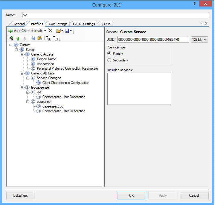
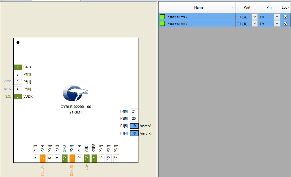
It is called a “stamp board” because it comes in a flat postage stamp-like postcard mailer.  Here is a picture of the front and the back (you can see that it has already lived a hard life riding around in my backpack).

IMG_2720

Here is the back of the mailer:

IMG_2722

In the picture you can see the yellow label proclaiming this to be an engineering sample.  It doesn’t seem like much, but when you pull back the front of the package you get to see the surprise:

IMG_2721-1

The kit can literally be broken into four separate pieces:

  1. The main board:
    • The PSoC4000S
    • A reset switch
    • A user LED
    • A user push button
    • A programming selector (to pick either the PSoC4000s or the PRoC BLE (that is on the back of the kit)) as the target of the programmer
    • All of the PSoC4000S pins are available on the 100mil center headers
    • A PCB footprint for a 10-pin ARM programming header
  2. A programmer board:
    • A PSoC5LP programmed with KitProg2 Firmware
    • A programmer mode button
    • 100mil center header with some of the PSoC5LP pins
  3. A Capsense slider user interface board with a 5 Segment Slider and 5 LEDs
  4. A Capsense button user interface board with 3 mutual capacitance buttons and 3 LEDs

145front-e

And the back, with the tiny 10mm X 10mm PRoC BLE module:

IMG_2706

Here is the schematic for the board:

CY8CKIT-145_PSOC_4A-S1-page1

CY8CKIT-145_PSOC_4A-S1 page 2

CY8CKIT-145_PSOC_4A-S1-page3

I wanted to build a project that would have two-way communication between my iPhone and the board, and would be compatible with the Swift App I had written.  The user of the board would have a capsense slider (and LEDs) of which the iPhone App could read the position.  In addition, it would have an LED that the iOS app could turn on and off.  Here is a demonstration that I filmed with my iPhone on the airplane:

In the next post I will describe the overall system and show you the firmware.