OK. We’re ready for the big moment: the user test. I was feeling pretty cool. I had spent the week talking to 100s of people and putting on a pretty good show. I was the master of all things PSoC, a geek rockstar. So I programmed the firmware. The slider worked. I was able to connect to the PRoC BLE from my app. But for some stupid reason the the PSoC and PRoC just were not talking and I had no idea why. And to make matters worse, I didn’t have anything I could (easily) use to debug the problem. So much for being the king of PSoC. I assumed that I had firmware bugs. I tried a bunch of different things, single stepping code, trying different pins, etc. But nothing worked. I couldn’t figure it out. It was intensely frustrating to be stuck on the airplane with a broken design.
As soon as I landed in Detroit, I logged in to get my email. I looked for messages from Rajesh (the PSoC Kit Manager) and sure enough, he had emailed me the missing schematic. After digging through the schematic, I found the error.
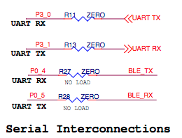
The connection between the PRoC and PSoC had a 0 Ohm resistor that was “No Load,” meaning the footprint was there, but the board manufacturer had not put on the resistor. This was done so that the pin could be used as a GPIO for something else.
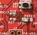
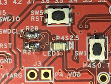
Here is a zoomed-in picture of the PCB:
The good news was, I was only one plane ride and an hour drive from my soldering iron. As soon as I walked in the door, I went straight to my lab.
Now everything works.
There are two morals to this story:
- Don’t go to immediately to your lab after being gone for a week, as it really irritates your wife.
- Look closely at the schematic.
You can find the PSoC Creator workspace on github in the directory called “capsenseble-145.”
Index
Description
PSoC4000s and the CY8CKIT145 Stamp Board - Part 1
The board and schematics
PSoC4000s and the CY8CKIT145 Stamp Board - Part 2
PSoC4000S Firmware
PSoC4000s and the CY8CKIT145 Stamp Board - Part 3
PRoC BLE Firmware
PSoC4000s and the CY8CKIT145 Stamp Board - Part 4
Debugging the problem
No comment yet, add your voice below!