In the previous Pinball post, I wrote about getting the OLED going and getting the footprint onto my printed circuit board. Now I need to make PSoC firmware to drive the display. I turns out that there are a number of different driver chips out there including at least SSD1306, SH1106, LD7032, SSD1325, and ST7920 that handle multiplexing the columns/rows, managing frame buffers, power management, etc. To make matters more fun, these chips support I2C, 3&4 wire SPI and a couple of different parallel interfaces (6800, 8080). I certainly didn’t want to go down the rathole of building up a complete driver library. But I didn’t have to, as it turns out that that Oliver Kraus built and open-sourced a very nice library that you can get at www.github.com/olikraus/u8g2. This library (and its predecessor u8glib) seem to be in pretty wide use in Arduino and Raspberry Pi.
In order to make the library work with the PSoC I had to do several things
- Download it from GitHub (git clone git@github.com:olikraus/u8g2.git)
- Created a new PSoC4200M project for the CY8CKIT-044 (which was the devkit that I happened to have sitting next to my computer)
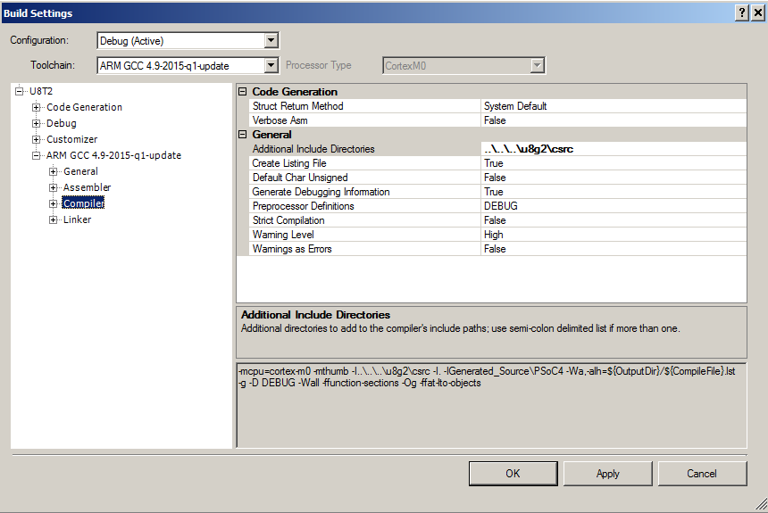
- Change the build settings (right click on the project and select building settings) then add the directory in “Additional Include Directories” and include the “u8g2/csrc” directory.
- Add the header files to the project by right clicking and selecting “Add->Existing item” so that the project can f
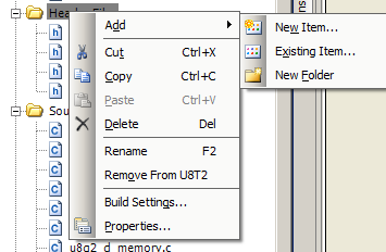
- Add the U8G2 C-Files to the project (same as step 4 but add the C files)
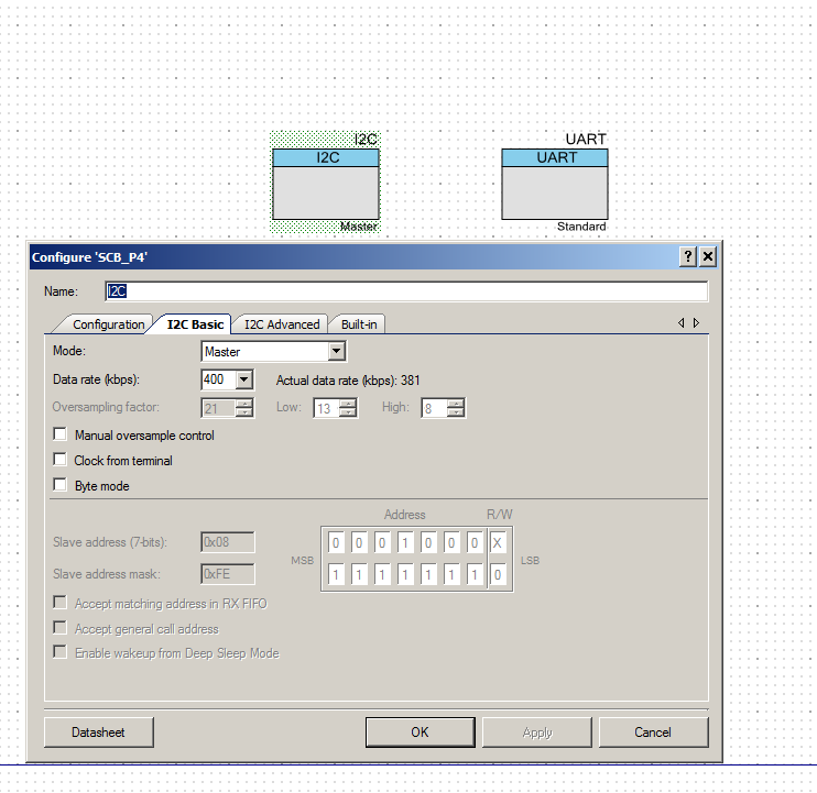
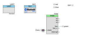
- Build a schematic which has an I2C (for the display) and a debugging UART. The I2C is configured as a master with 400kbs data rate. The UART uses the default configuration.
- Assign the pins

Now I am ready to build some firmware that will drive the display. In order to use the library with a PSoC I need to create two functions for the U8G2 HAL to use as an interface to the PSoC hardware. You initialize the U8G2 system with a call to the u8x8_Setup function. In that call you need to provide function pointers too the two HAL functions
- The GPIO and Delay Interface
- The byte oriented communication interface
This is an example of the setup required:
![]()
The GPIO and Delay interface is used by the byte oriented communication functions to read/write the GPIOs and provide delays. This function provides the underpinnings of a bit-banged I2C, UART, SPI etc. Because I am only going to use PSoC Hardware to provide the I2C interface I will only respond to the delay messages. All of the delay functions are implemented as busy wait loops, which I am not a big fan of. The input to the function is a “message” that is one of a sprawling list of #defines in the file u8x8.h. I believe that I found all of the possible cases, but I am not sure.
The first message, UX8X8_MSG_GPIO_AND_DELAY_INIT doesnt need to do anything because the GPIOs are configured correctly by the default.
I did not respond to the messages of the form U8X8_MSG_GPIO_X which are the read and write of the GPIOs as I am not going to use the bit-banged interface.

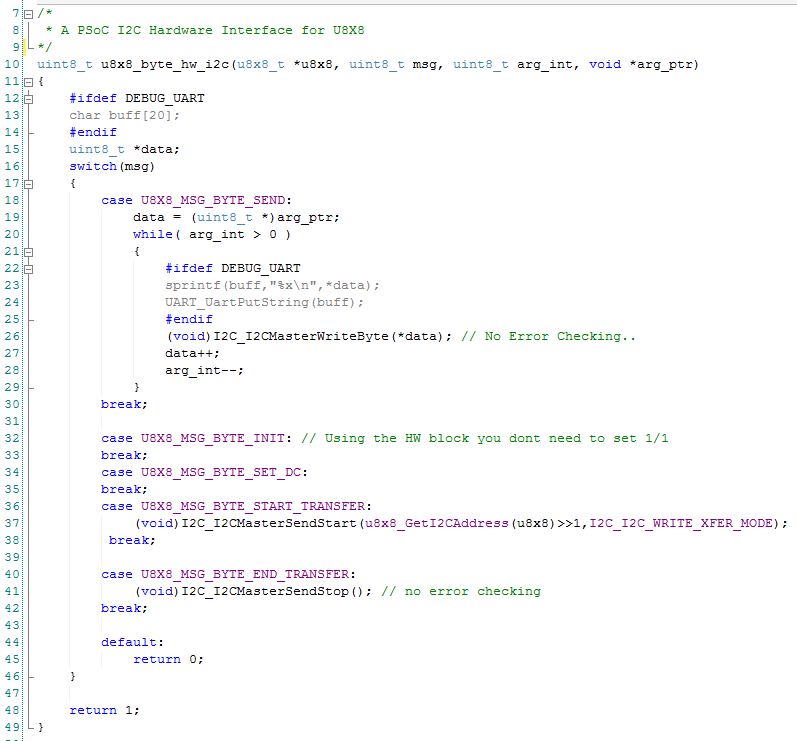
The other function that needs to be provided is the byte-oriented communication function. This function needs to respond to the messages to start, send, and end communication. I just mapped those messages onto the PSoC hardware APIs. While I was trying to understand what was happening with the system I implemented a debugging UART which you can see in the #ifdef DEBUG_UART sections.
You can find all of the source code and files at the IOTEXPERT site on github.
Index
Description
Pinball: Newton's Attic Pinball
An introduction to the project and the goals
Pinball: Lotsa Blinking LEDs
Everyone needs a bunch of LEDs on their Pinball Machine
Pinball: Matrix LEDs (Part 1)
Saving PSoC pins by using a matrix scheme
Pinball: Matrix LEDs (Part 2)
Solving some problems with the matrix
Pinball: Matrix LEDs Component
How to turn the Matrix LED into a component
Pinball: A Switch Matrix
Implementing a bunch of switches
Pinball: Switch Matrix Component (Part 1)
The switch matrix component implementation
Pinball: Switch Matrix Component (Part 2)
The firmware for matrix component
Pinball: Switch Matrix Component (Part 3)
Test firmware for the matrix component
Pinball: The Music Player (Part 1)
The schematic and symbol for a Music Player component
Pinball: The Music Player (Part 2)
The Public API for the Music Player component
Pinball: The Music Player (Part 3)
The firmware to make the sweet sweet music
Pinball: The Music Player (Part 4)
The test program for the music player
Pinball: The Motors + HBridge
Using an Bridge to control DC Motors
Pinball: The Eagle Schematic
All of the circuits into an Eagle schematic
Pinball: The Printed Circuit Board 1.0
The first Eagle PCB layout of the printed circuit board
Pinball: The PCB Version 1.0 Fail
Problems with the first version of the Eagle PCB layout
Pinball: PCB Layout 1.2 Updates using Eagle
Fixing the errors on the first two versions of the Eagle PCB
Pinball: Assemble and Reflow the 1.2 PCB
Assembling the Eagle PCB
Pinball: Testing the Eagle PCB
Firmware to test the newly built Pinball printed circuit board
Pinball: Debugging the Motor Driver
Fixing the motor driver PSoC project
Pinball: Hot-Air Reworking the Accelerometer Solder
Using a Hot-Air Rework tool to reflow a QFN
Pinball: Debugging the LM317 Power Supply- A Tale of Getting Lucky
Debugging the LM317/LM117 power supply
16 Comments
Hi, i cloned your repository and there’s a missing file (u8x8hal.h), couldn’t find it on the u8g2 repository, anyways the project compile successfully :).
Yes. I was/am planning on moving the code that makes the hardware access layer work into that file instead of having it in main. But I can’t decide the best way to implement it. As soon as I figure it out Ill do that.
Really I want to make it all a component… but Im don’t want to permanently freeze his source code into the component as it continues to change… so I am not sure.
Email me (engineer@iotexpert.com) your real address and Ill send you development kit for pointing out my error.
Alan
Hi Alan,
Thanks for the kit, just sent you my address :D.
Maybe to keep track of the changes on the u8g2 source code you can add it’s repo as a git submodule on the custom component repository.
Carlos
The real problem is that there is a flaw in the design of the HAL… I have itchy fingers to fix it… but don’t really have time… that is what kept me from really dealing with the problem.
Hello Alan,
I have been wondering if this is still the best starting point to interface PSOC 4 to SPI e-ink display in your opinion?
/Alex
If that EINK display driver is in the library… then yes I think that is best. But I dont know which one you are talking about.
Hello Alan,
I was trying to use your example of driving a OLEd dispaly from IOTexpert. I have a 042 kit and am having trouble compling you example code. My erroe tells me that it is unable to load …. Unable to find the file on disk: “C:\Cypress Files\U8G2\u8g2\csrc\u8g2_bitmap.c”. What am i missing, i have setup the build settings as you instructed.
Scott
I suspect that you have not added all of the .c files to your project.
Hi Alan, In CYW20719 what can be used for U8X8_MSG_DELAY_* instead of CyDelay*?
Thanks
I don’t know… everything I could imagine would be more complicated… you could use SysTick or if you are running an RTOS like FreeRTOS your could use vTaskDelay.
What is wrong with CyDelay (for an application like this?) … obviously it is a busy wait which isn’t ideal. I suppose that if I did it again it would be done with FreeRTOS. In fact you can see that I wrote several articles about using Segger where I did vTaskDelay
I don’t see anywhere CyDelay or Cy_SysLib_Delay in the API for the CYW20719 – this is the only reason I’m looking for something like this?
The only place in WICED Studio 6.2.1 I could see them is for 43xxx platform, not for CYW20719 or any other of the included platforms.
Thanks
Oh… I thought that you were talking about PSoC 4s (or 6’s).
For 20719 if you do something like this you can use wiced_rtos_delay_millisconds
Thanks Alan,
Any idea for the smaller delays: 10MICRO and 100NANO?
The only problem with wiced_rtos_delay_milliseconds I see so far is I cant find any information about the RTOS threads that are automatically started what serve they and what priority have, so not to mess the bluetooth communication with such delay if they will run on the same thread. Even if I make a dedicated thread, need to find what priority to put there (lower than BT) … but will try … this WICED/20719 is quite a challenge 🙁
Regards
That chip has an RTOS running in it with a 1ms tick. If you are trying to time things at the 100micro or 1micro level you are going to be in trouble with the bluetooth. The Bluetooth threads are very timing critical to keep things going.
Alan
Ooops, there is wiced_rtos_delay_microseconds, so only left the nanoseconds part of the question. Thanks
Thats cool.. I didn’t know that… I’m quite sure that uS delays are implemented as busy wait.
Alan