Pattern Agents are running a crowd funding effort for TSoC … here
Summary
In the previous post I told you that I immediately blew away the factory firmware on the TSoC4L board. I’m like that sometimes :-). In this post I am going to take you through the entire process of getting and reprogramming the factory firmware, then finding and debugging a PSoC4 clock problem. The rest of this post is:
- Getting the correct firmware back on the TSoC4L Board
- Running into a bug in the beta version of the firmware
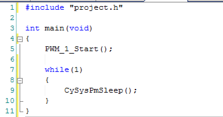
- Using the debugger to find the bug
- Explaining the functionality of Low Frequency Clocks and the Watch Dog Timer
- The Pattern Agents bug fix
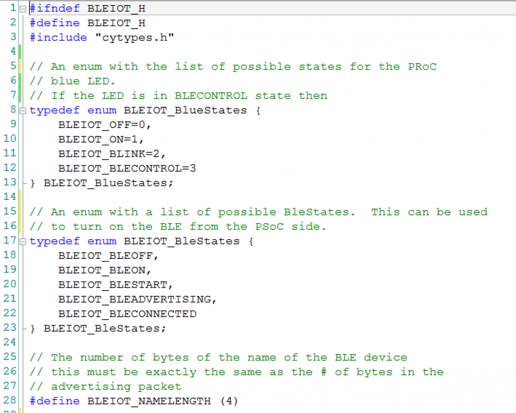
Factory Firmware
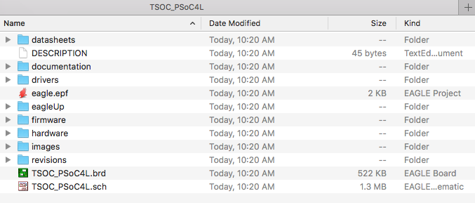
Getting things going again starts with “git”ing the firmware. This can be done by “git clone git@github.com:PatternAgents/TSOC_PSoC4L.git”. Once you have the repo cloned you will find a bunch of good stuff including:
- datasheets: All the datasheets
- documentation: The PatternAgents documentation (quick start)
- drivers: The windows USB <-> UART drivers
- eagleUp: JPG renderings of the PCB
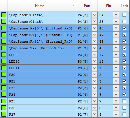
- firmware: The PSoC Creator Project
- hardware: gerbers, boms etc
- images: renderings of the board, photos of the board etc
- revisions: old revisions of the Eagle project files
- The Eagle PCB Project including schematic and layout
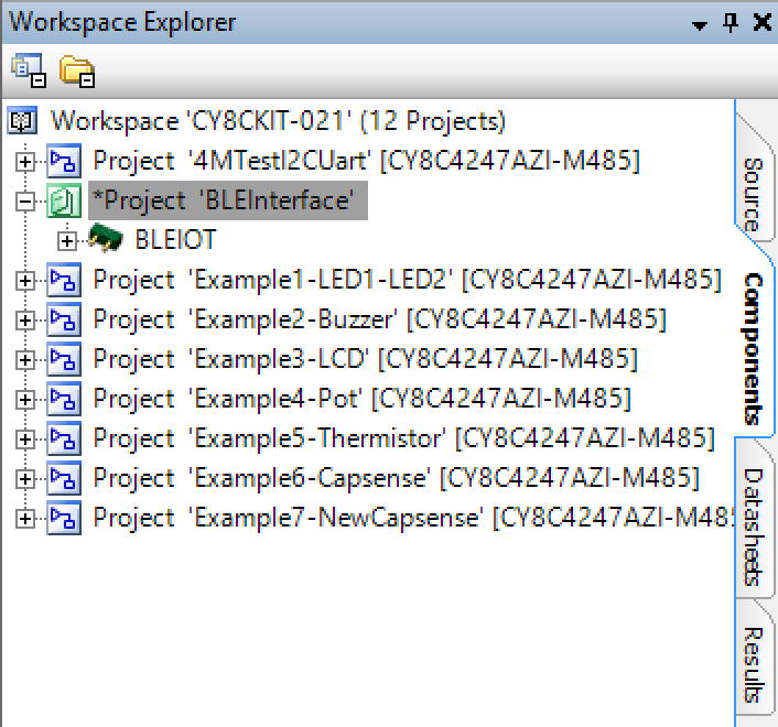
When you open the PSoC Creator Workspace you will find two projects
- A USB Bootloader – called “USBFS_Bootloader”
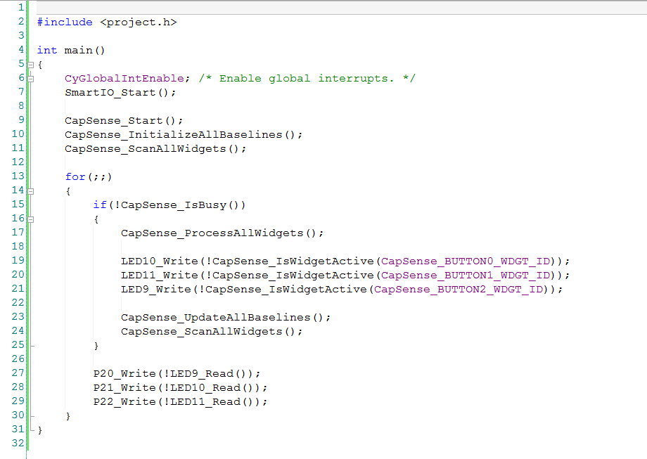
- The TSoC RSVP Firmware – called “rspvsis_4l_typ”
The system is supposed to
- Start the USB HID bootloader (so you could get new firmware). Wait for 10 seconds for a bootloader host to start then if it doesnt … then start
- The RSVP Firmware
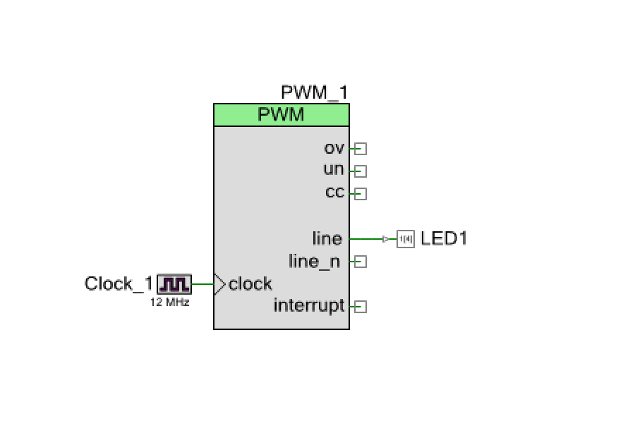
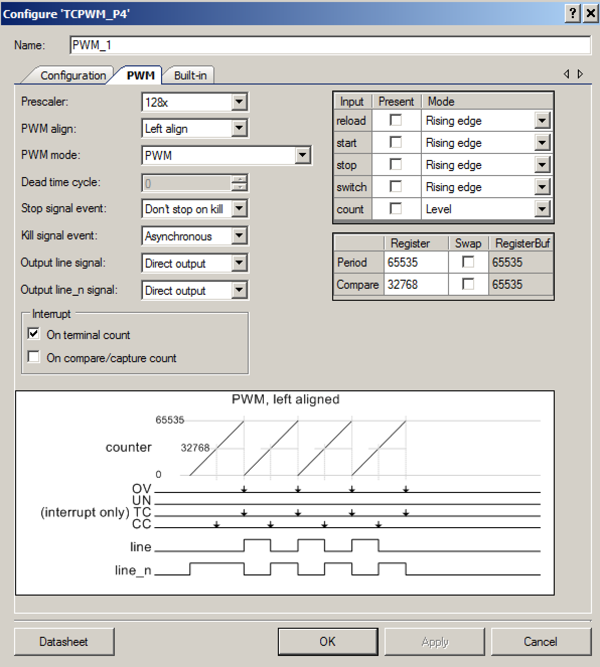
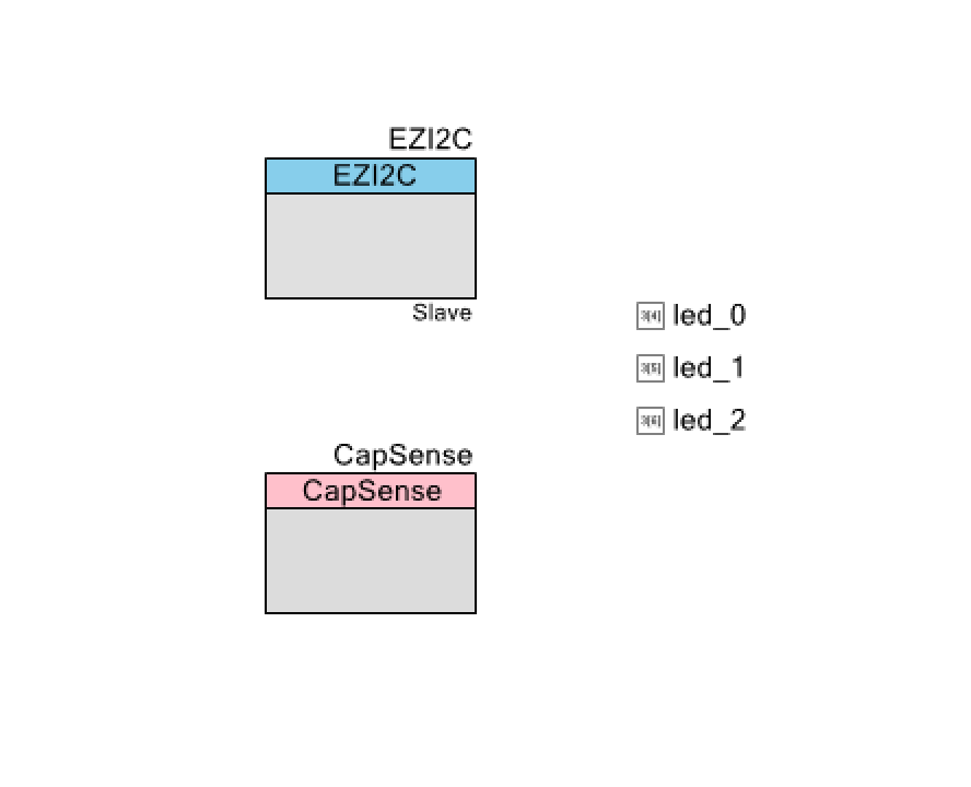
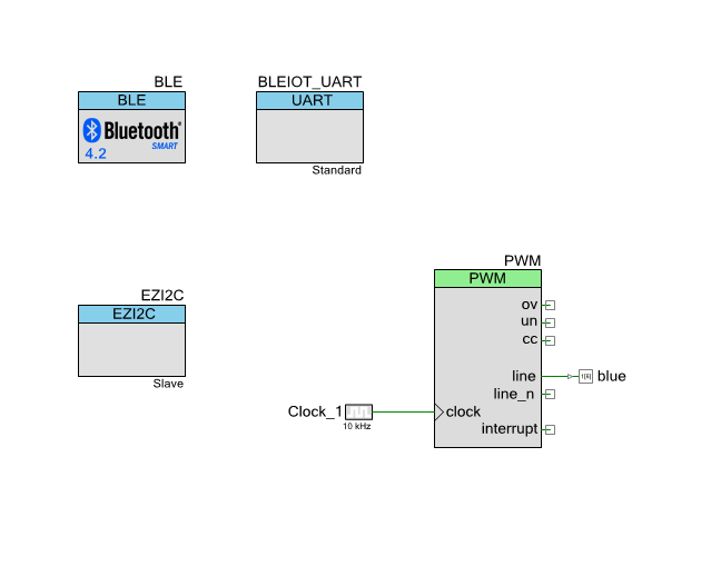
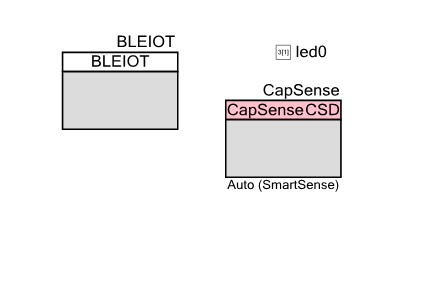
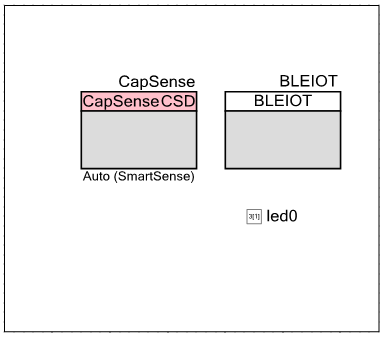
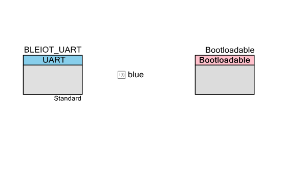
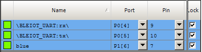
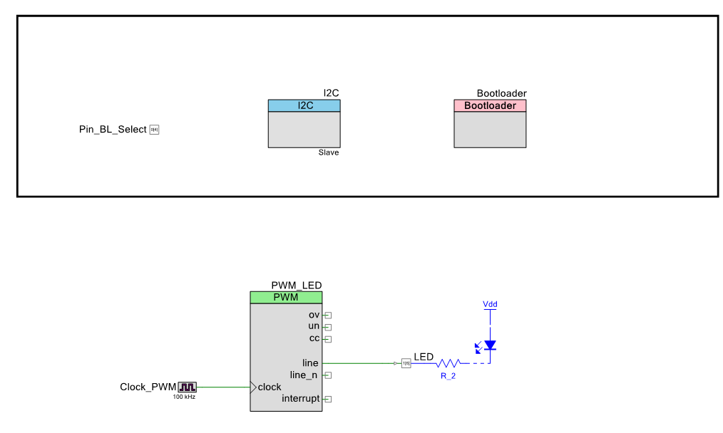
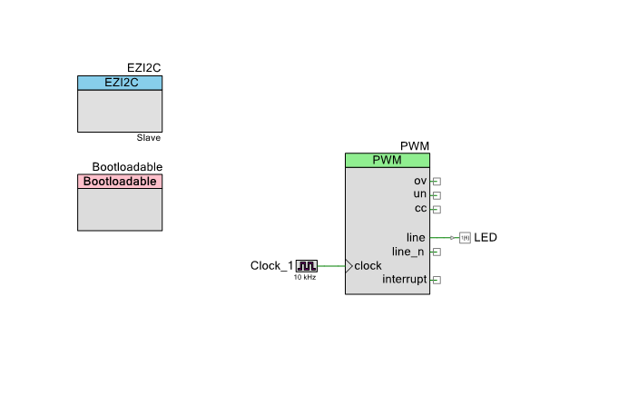
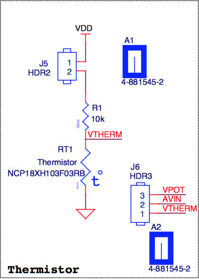
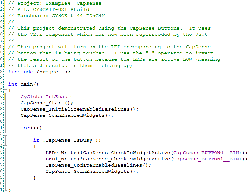
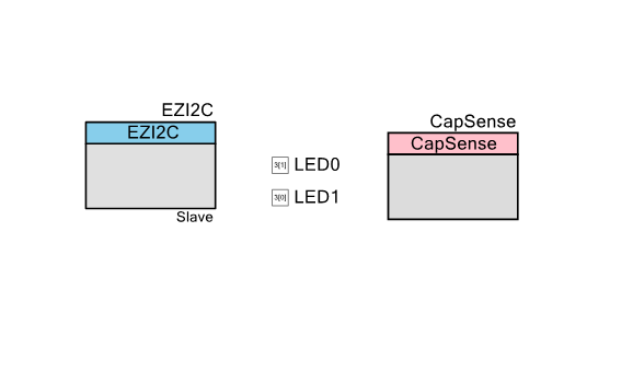
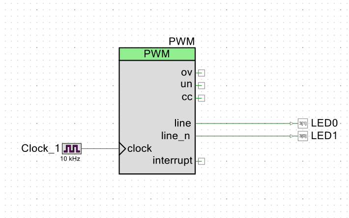
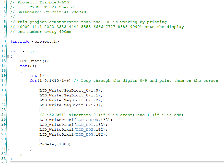
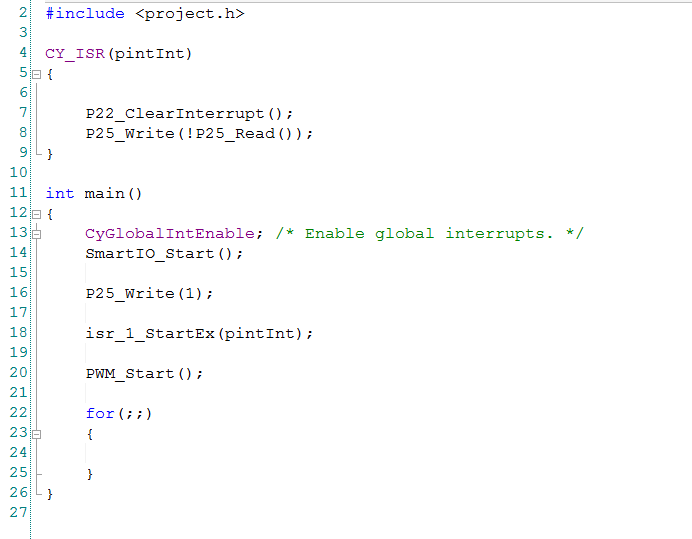
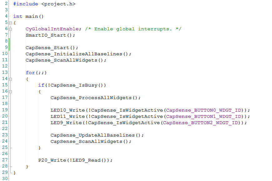
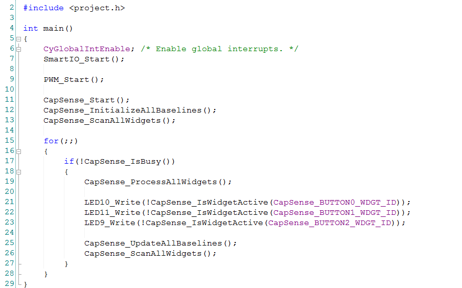
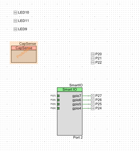
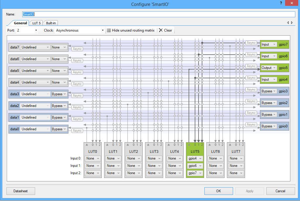
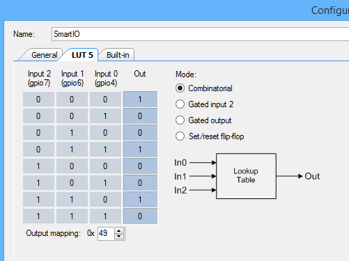
When you plug in the board you will see the TSoC4L enumerate as “Cypress ThingSoc Bootloader”. Then, after 10 seconds, you should see it reboot, then enumerate as “Cypress USB UART”. But, this was not happening for me. Why? I wasn’t sure. The first thing that I did was add a blinking LED circuit that looked like this:
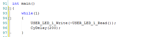
But the LED was not blinking. That meant that the firmware was not even getting to main i.e. it was hanging BEFORE main in the PSoC boot code. But where and why?
Using the Debugger to Find the Bug
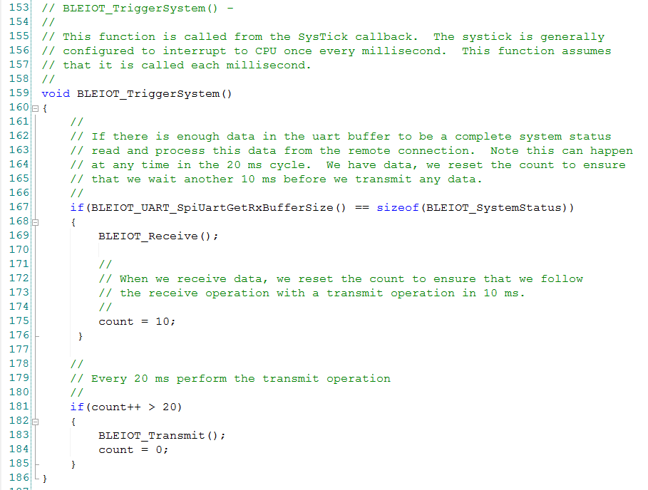
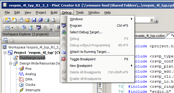
How do you figure out where the system is stuck if you can’t even use the “blinking LED” or “printf” debug? Simple. Use the debugger. Start by programming the PSoC with your firmware. Then click “Debug->Attach to running target”.
The debugger will start. Then you will be able to press the “Pause” button. which will take you to a screen that looks like this:
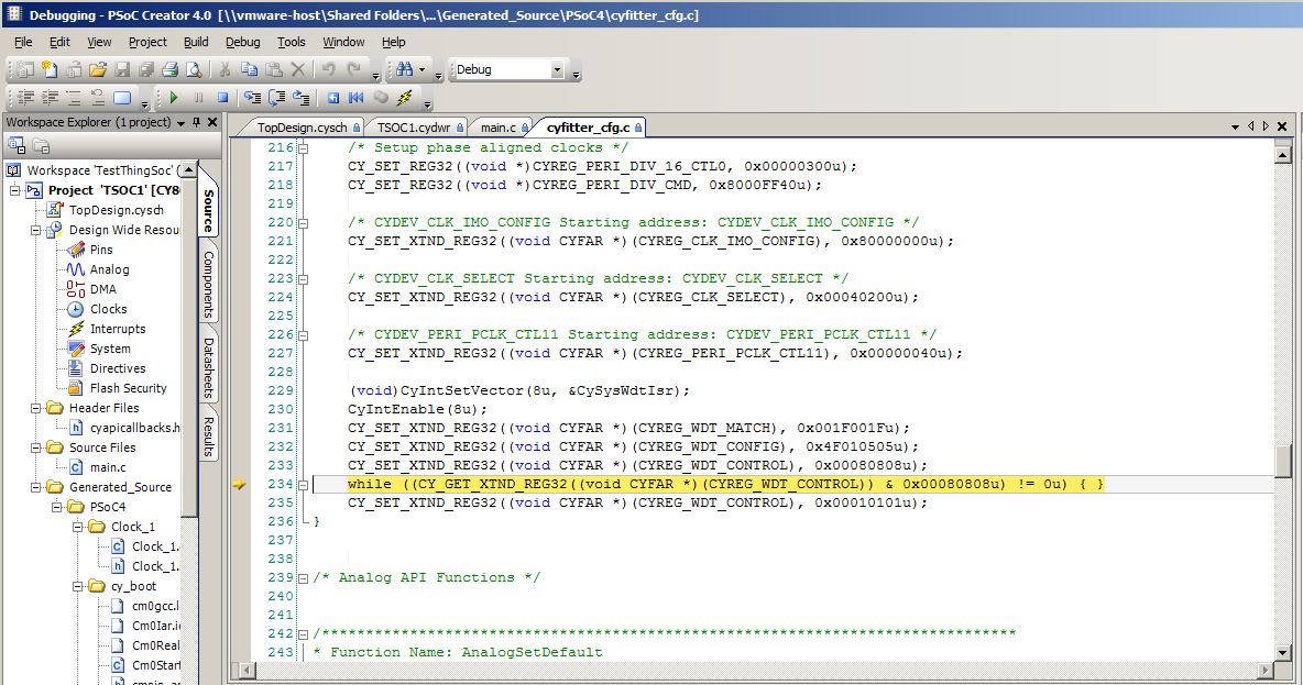
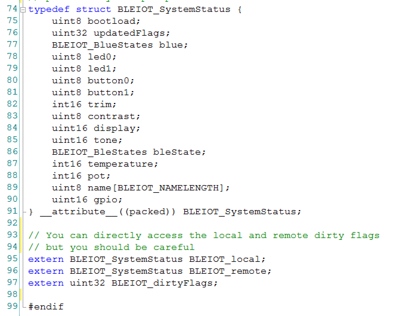
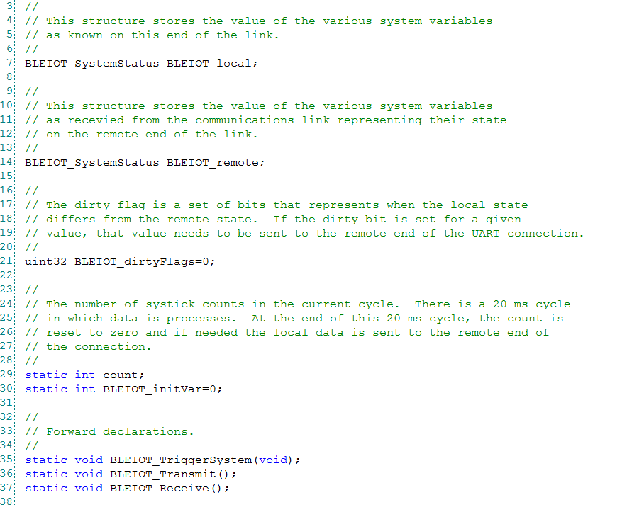
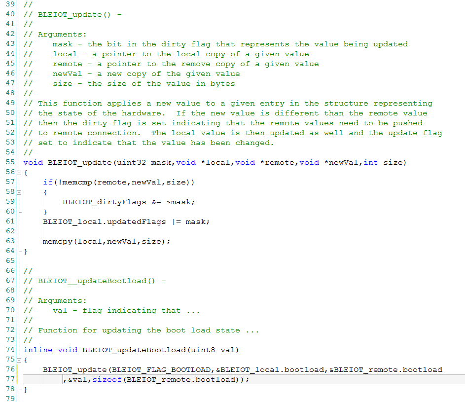
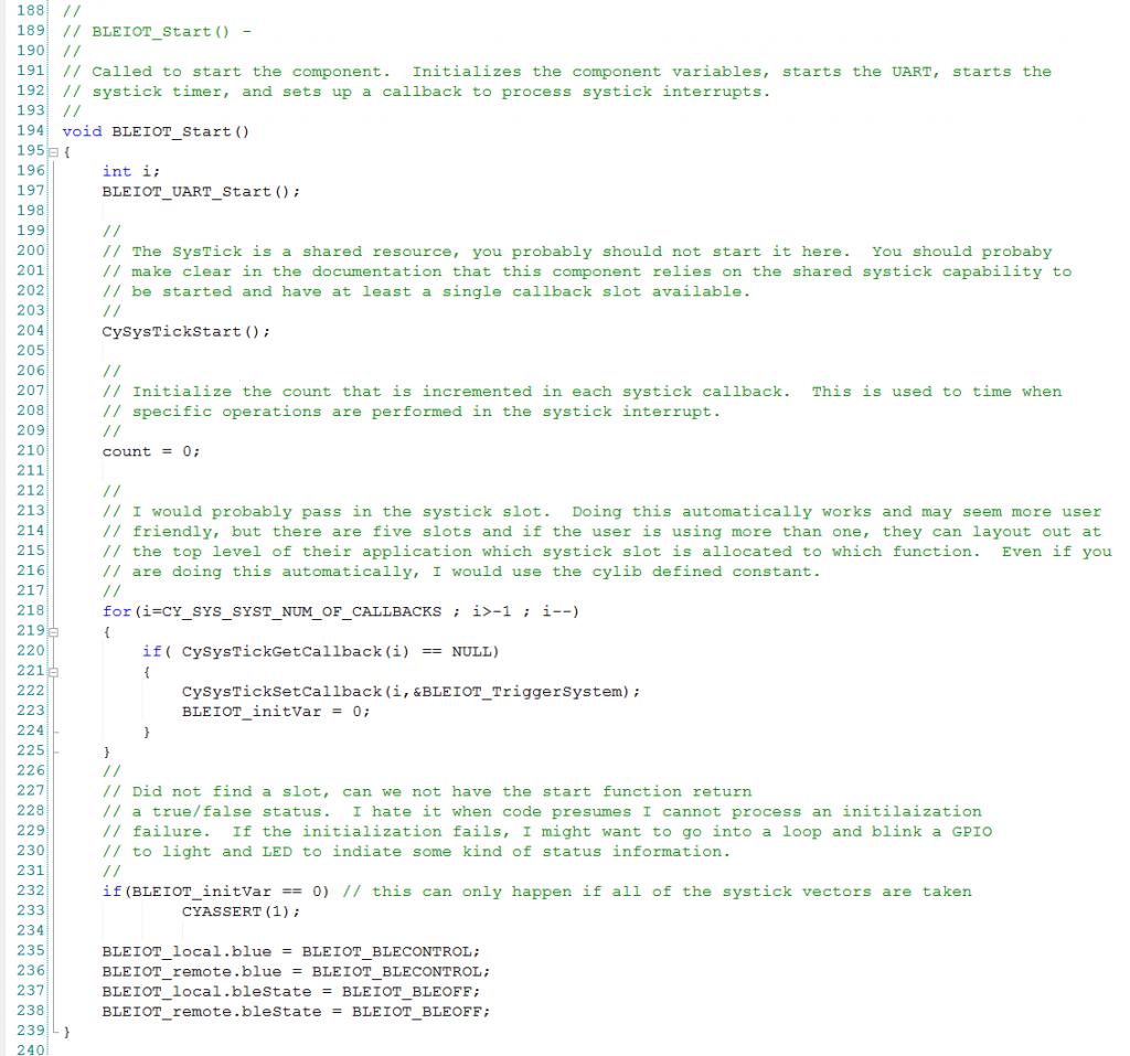
The chip is stuck on line 234. What does line 234 do? That is a busy wait loop. It is waiting for the Watch Dog Control Register to clear. To explain that, I will need to take you through the PSoC4 Low Frequency Clocks. First you should notice that the file we are in is named “cyfitter_cfg.c”. What is this file? If you look at the top, this is what PSoC Creator says.
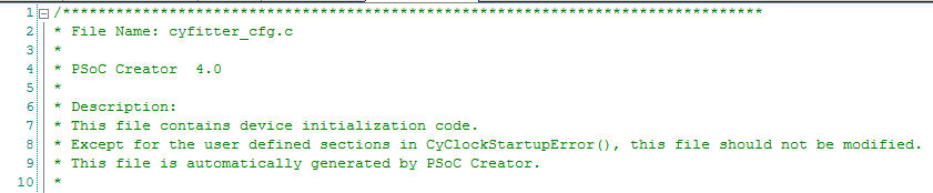
This means that the “cyfitter_cfg.c” file is synthesized by PSoC Creator when you do a build based on what you configured when you setup your project. This file contains a bunch of the startup code including the code that gets the clock systems going. Line 234 is inside of a function called “ClockSetup”. All of this code is called BEFORE you get to main().
The PSoC4 Clock(s)
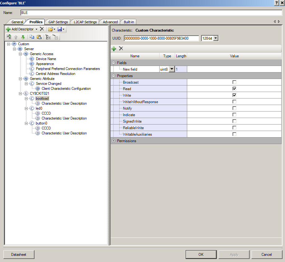
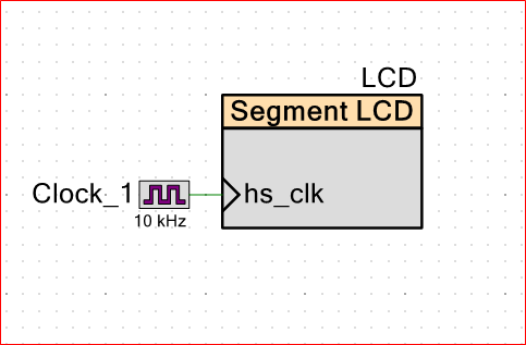
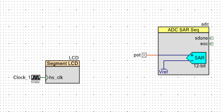
To explain why we are stuck there you first need to double click on the “Clocks” tab in the Design Wide Resources. When you do that it will take you to this screen which contains a bunch of information about the clocking system in the PSoC.
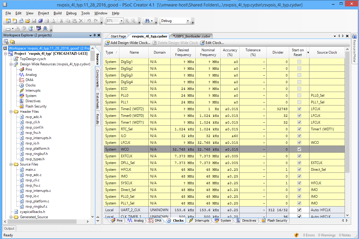
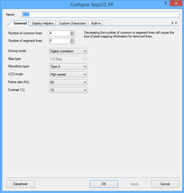
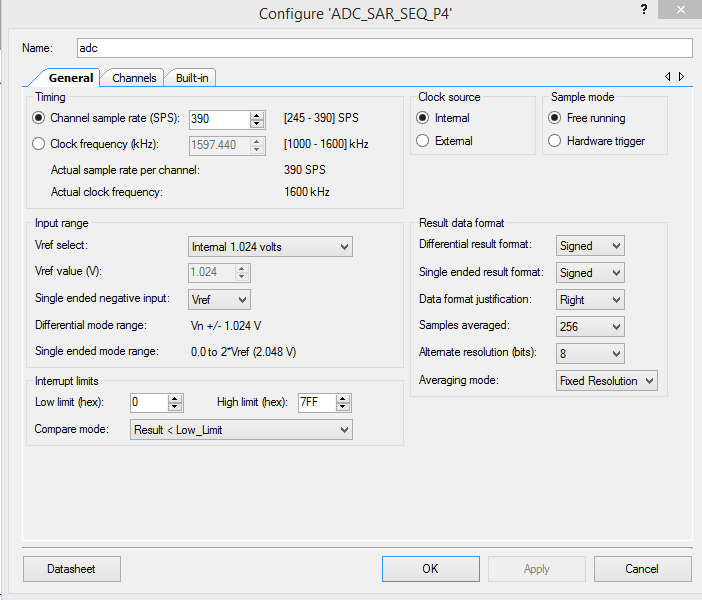
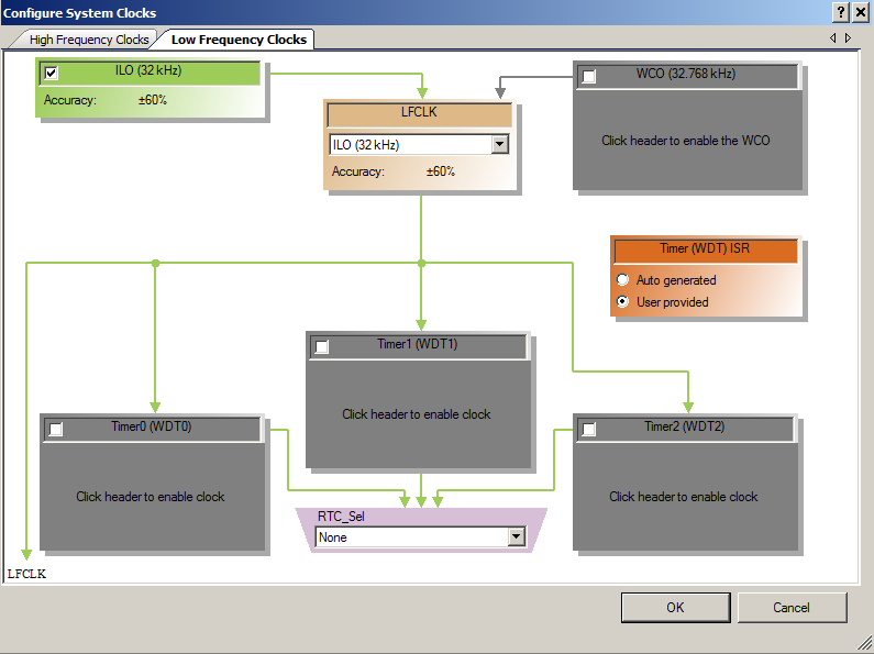
In the screen above, you can see that there are three Timers in the Watch Dog Timer system (WDT) that are clocked (i.e. have a Source Clock of) by the Low Frequency Clock (LFCLK). The LFCLK has its source as the Watch Crystal Oscillator (WCO). If you double click the WCO line it will take you to a screen that is much easier to see what is going on, specifically the “Configure System Clocks” screen:
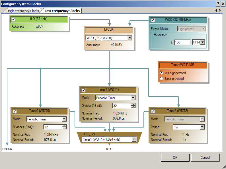
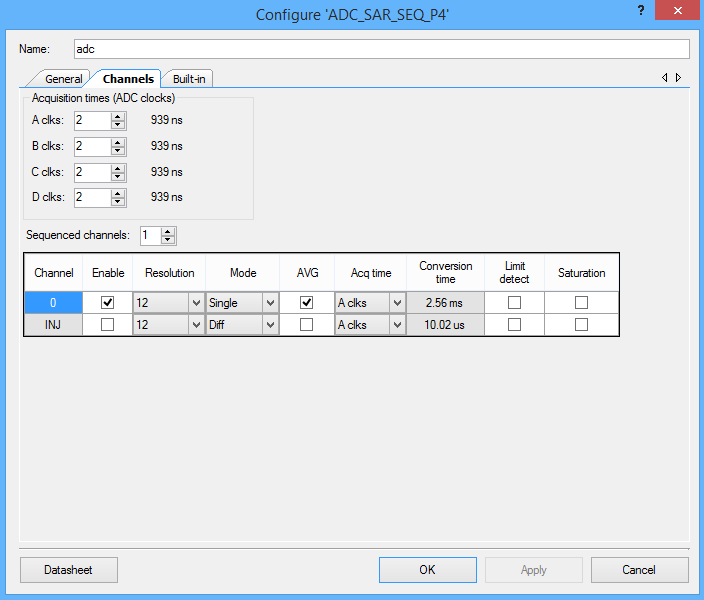
In the screen above you can see that the LFCLK has two choices of oscillator sources, the “ILO” or the “WCO”. ILO stands for Internal Low Speed Oscillator. The ILO is a fairly inaccurate (+- 60%) RC oscillator that is built inside of the chip. It is designed to be very low power which is why it is so inaccurate. If you need a more accurate oscillator, then you should use an external oscillator, specifically a Watch Crystal Oscillator or WCO. A WCO is a 32.768KHz crystal oscillator. These watch crystal oscillators give you very precise clocks that can be used to drive real time clocks accurately.
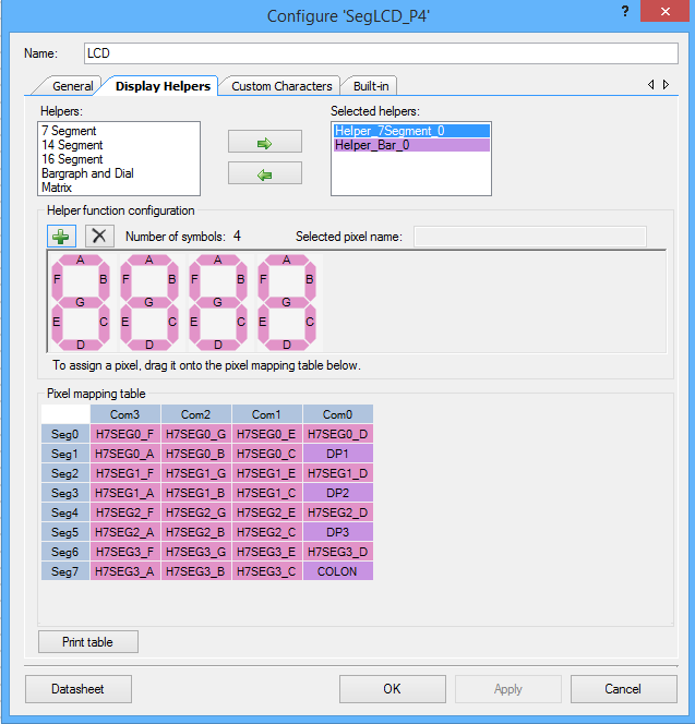
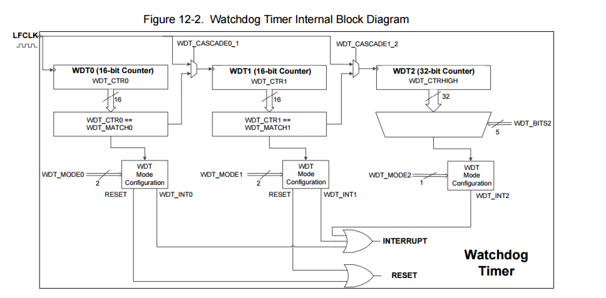
The next thing to see is there are three Watch Dog Timers (WDT) numbered 0-2. These times are driven by the “LFCLK”. Here is a picture from the PSoC Technical Reference Manual.
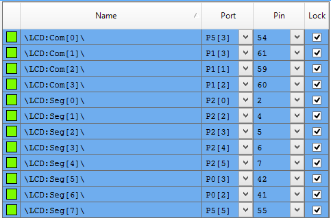
So what is the “CYREG_WDT_CONTROL”? You can find that by looking in the PSoC4 Registers TRM.
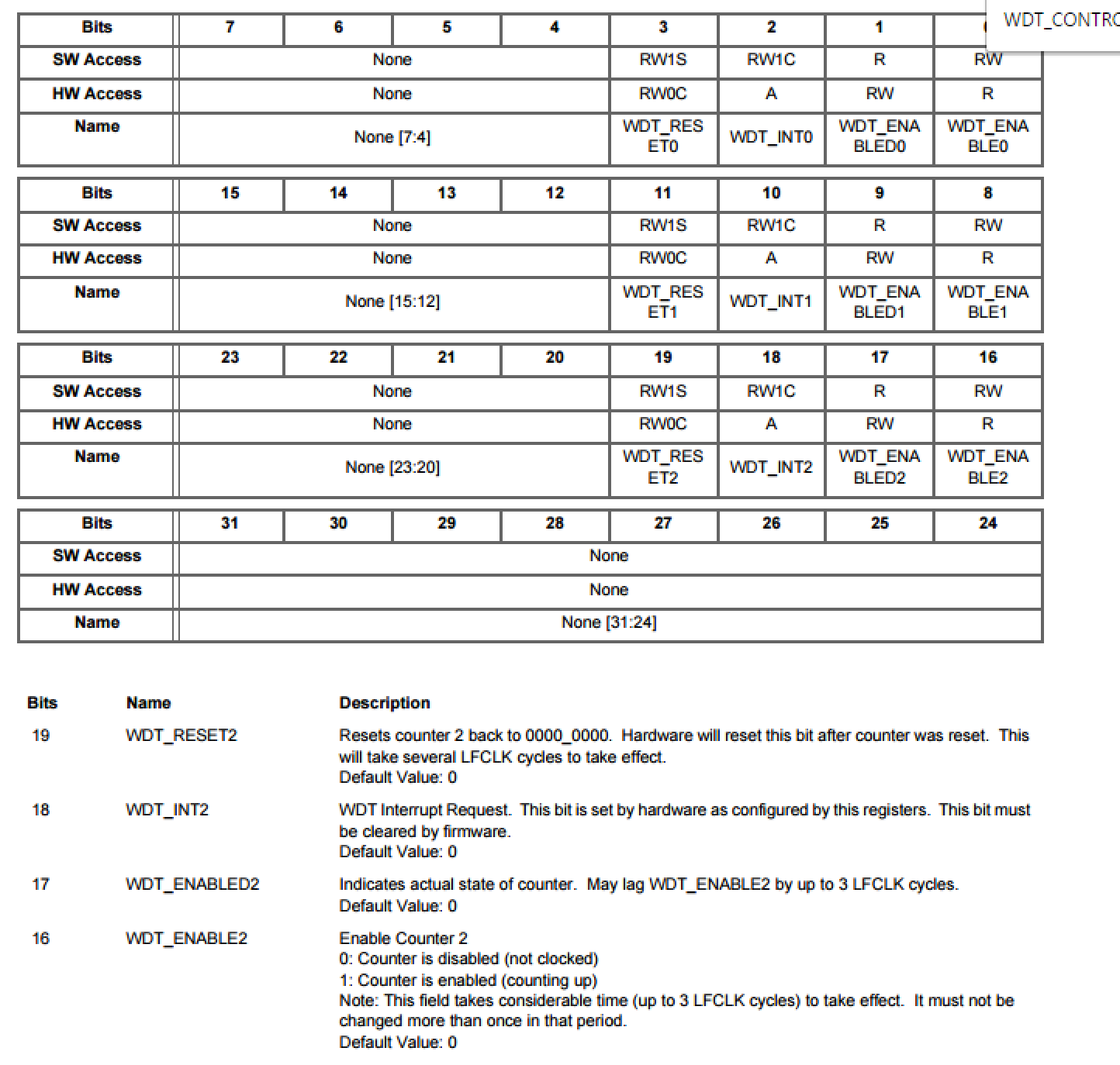
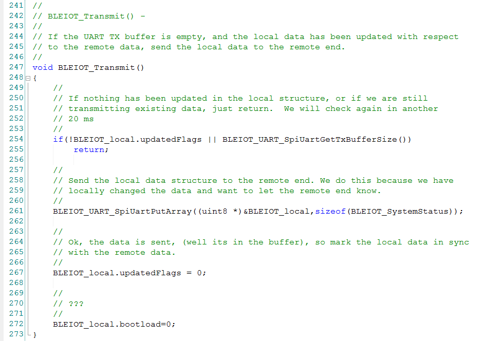
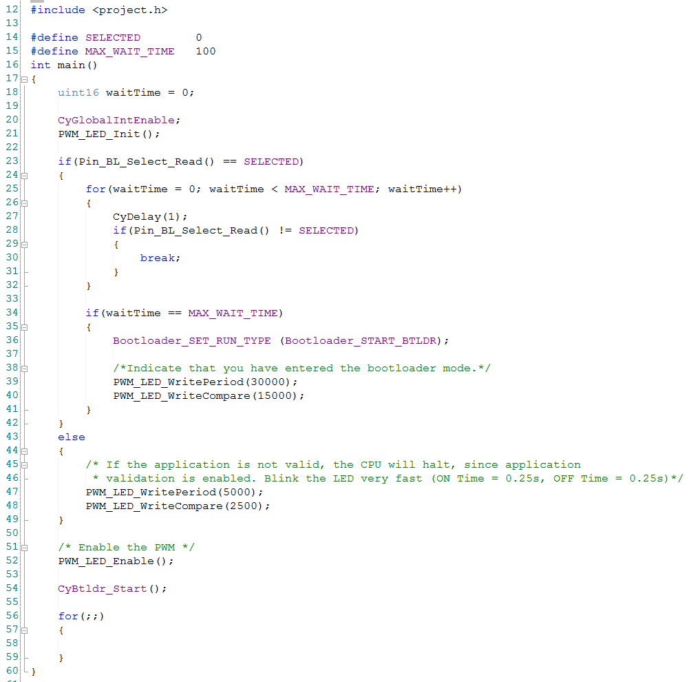
The busy wait loop is waiting for bits 19,11,3 to be cleared. Those bits are “WDT_RESETx” They become 0 when the three WDT timers are cleared which happens “several LFCLK cycles” after the reset. As a reminder, here is that block of code:
![]()
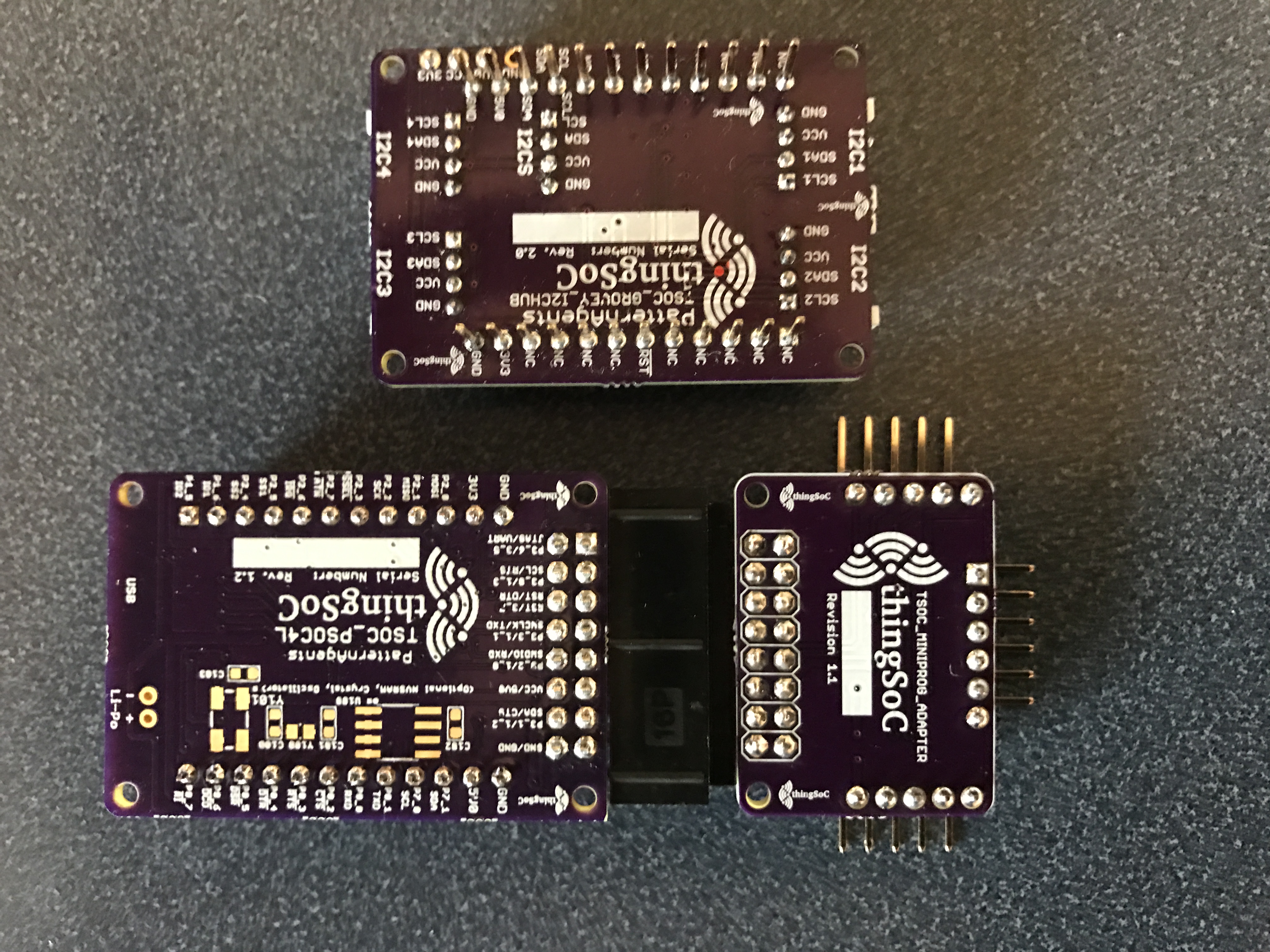
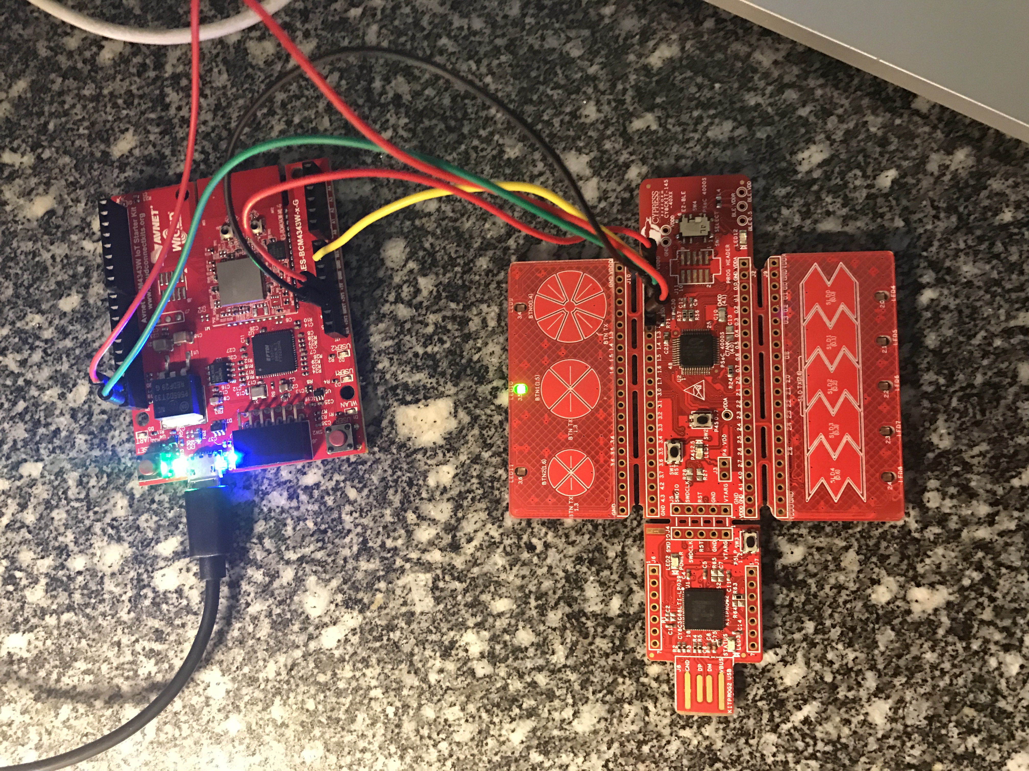
This still leaves us with the question, “What is the problem?”. If you look on the back of the ThingSoC4L board you will see there is no Crystal populated on this board. (the blank footprint on the right side of the back). The WCO is an optional feature from Pattern Agents. If you need the more accurate timing, you need to solder on your own Crystal.
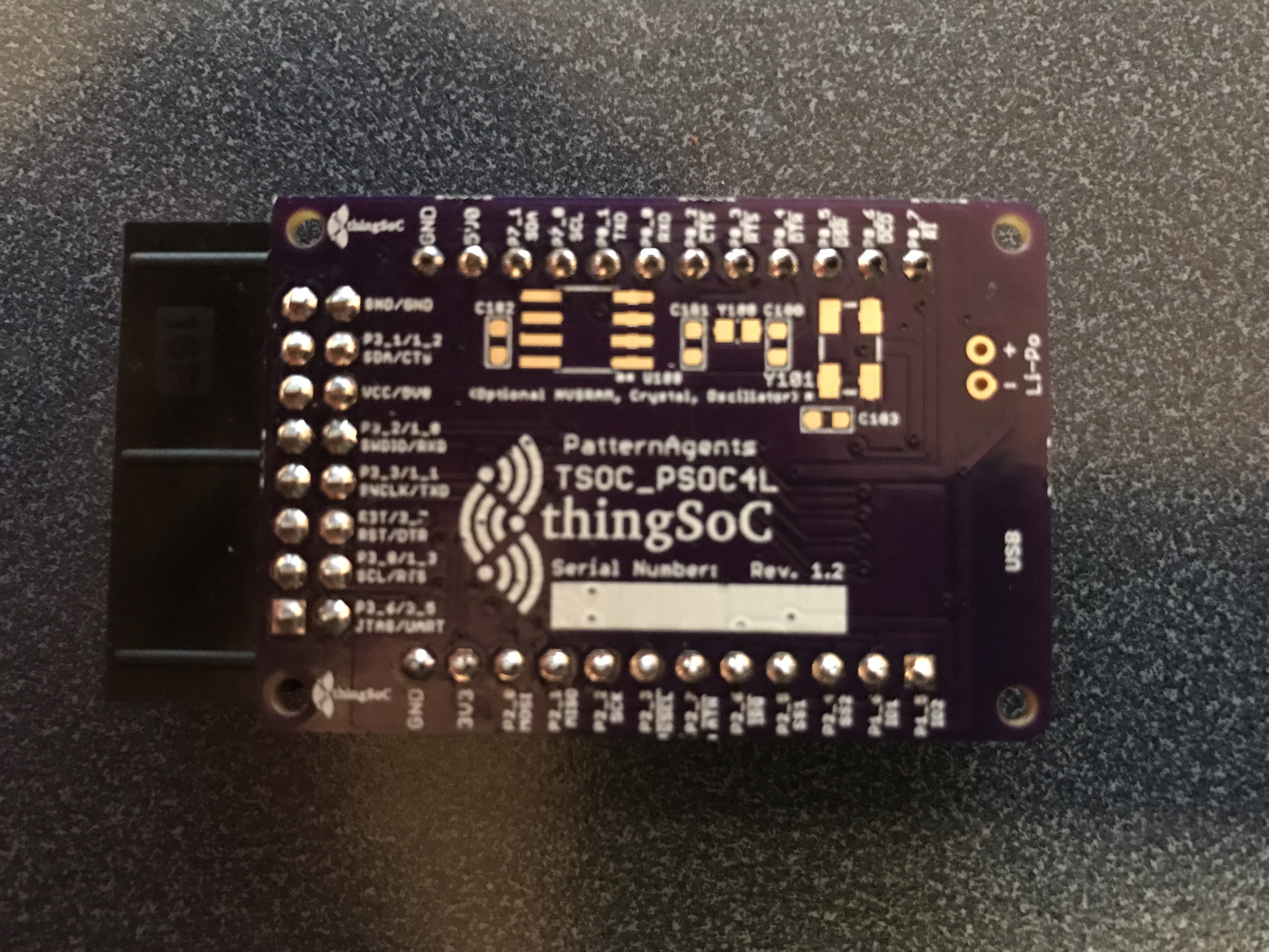
If there is no WCO crystal, then the WDT timer reset will never happen because LFCLK isn’t doing anything. And, the busy wait loop will never end. Mystery solved.
The Pattern Agents Bug Fix
To fix the startup problem, the Pattern Agents guys changed the clock configuration to
- Turn off the WDTs
- Use the ILO as the source of the LFCLK
You can find all of the projects in the TSoC Series at my GitHub ThingSoC repository git@github.com:iotexpert/ThingSoC.git
Index
Description
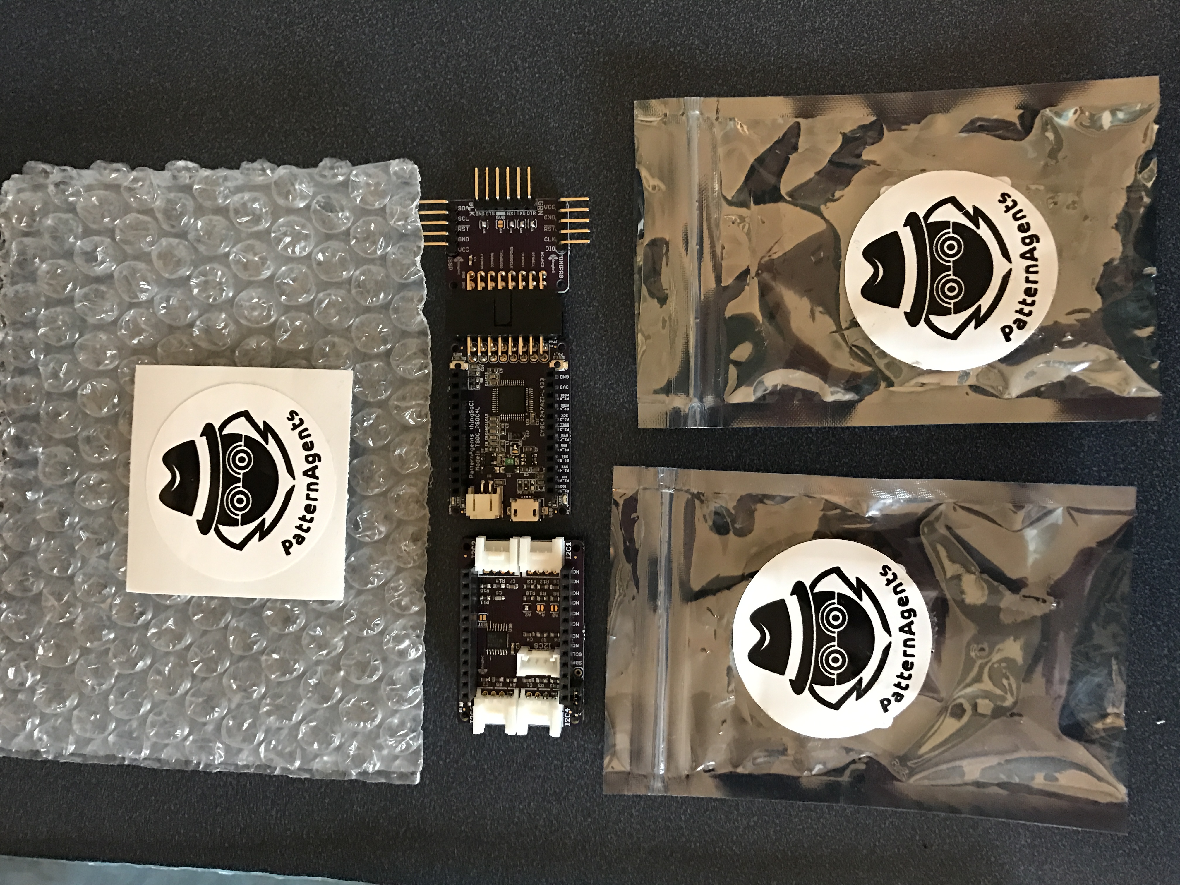
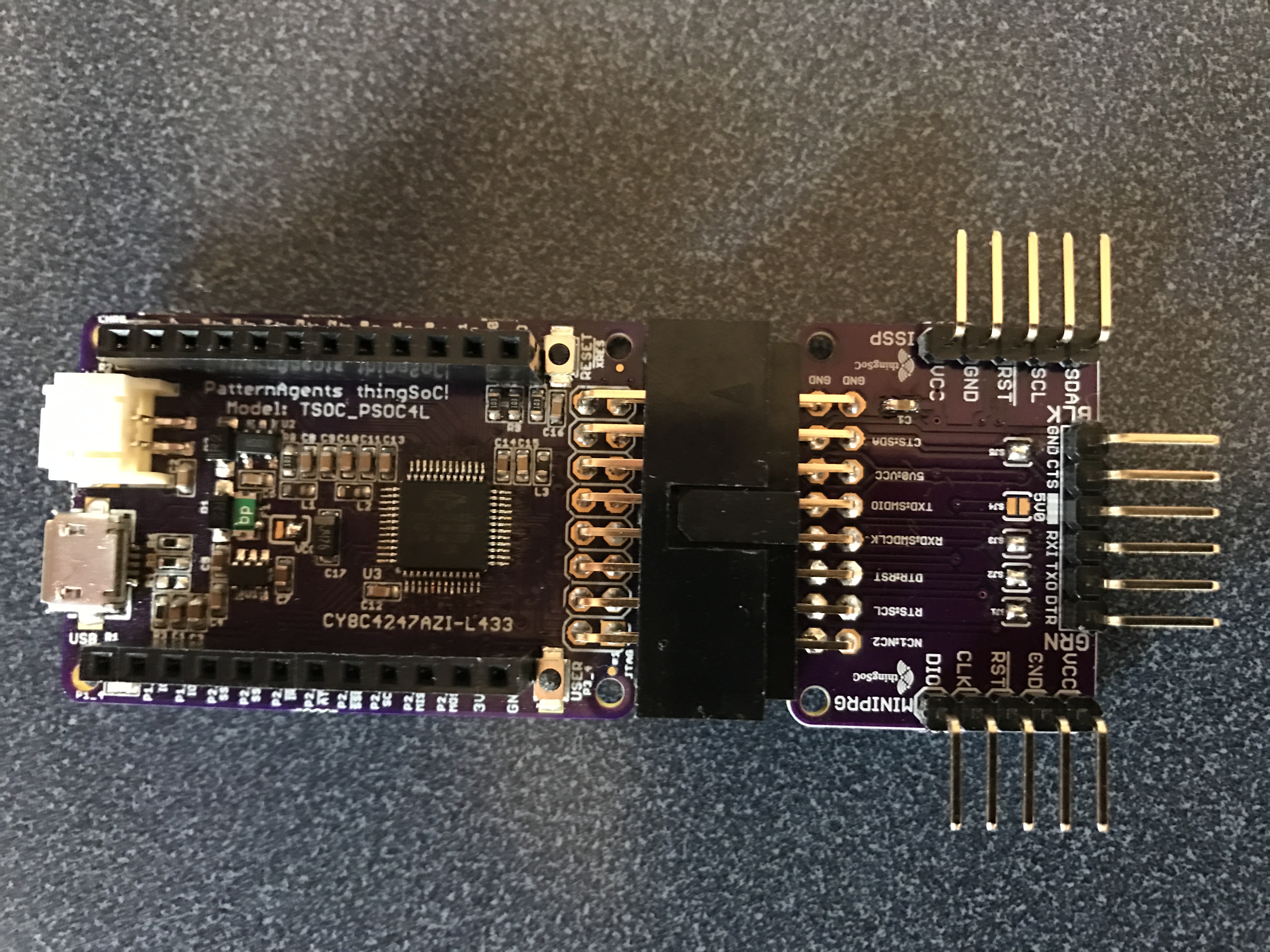
ThingSoc: TSoC PSoC4L Development Kit from PatternAgents
Introduction to ThingSoC
ThingSoC PSoC4L: Using & Debugging the PSoC4 Clock
Debugging a beta firmware problem
ThingSoC: The TSoC GROVEY I2CHUB : I2C Hub/Switch
Evaluating the ThingSoC I2C Hub
ThingSoC: Multiple I2C Displays
Using the I2CHUB and U8X8 Library
A project using ThingSoC I2C Hub & 4 OLED Displays