Summary
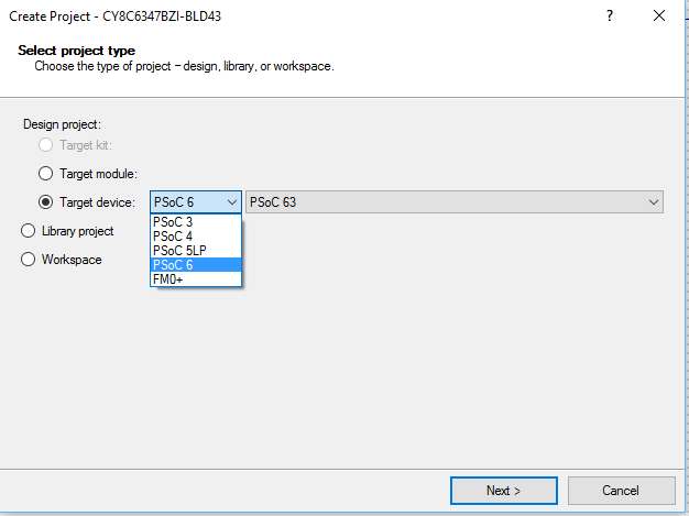
I spent all day Saturday working on the firmware for the next post in my series of articles about PSoC4 BLE Centrals. Then, after dinner I checked my email for alan_hawse@cypress.com, where I found an email from a customer in California who was having a problem with a PSoC 5 Timer. He had already posted on the Cypress forum and did not have functional answer. I always like using PSoC 5, so I looked at it for a while (until my wife started yelling at me about working), then right before bed, I sent him a short statement of the cause and told him that I would send the project on Sunday.
Sunday around noon I posted a couple of working projects to the forum… but… and there is always a but … I didn’t really like the answer so I kept working on it. Finally at 3:08 (yes exactly 3:08) I stopped because there was one part of my solution that I didnt like. So, I called my PSoC secret weapon, specifically, the bad-ass engineer Greg. I explained my problem and literally 10 seconds later he gave me a good fix, which I implemented and then sent off to the customer.
This article doesn’t really have much to do with IoT, except that the engineer who sent me the problem originally is using an RC servo motor remote control (I think). RC, thats wireless right? that counts as IoT, right :-)?
Here we go. The original email says “I am simply trying to measure the pulse width of a signal that ranges from 1 to 2ms. I can easily do this on an Arduino using pin change interrupts but I wanted to implement this on a PSOC so I decided to use the timer component”. I thought, “OK, that makes good sense, we will do that”.
In this article I will:
- Explain the Cypress PSoC 5 Timer functionality
- Show the problems in the original implementation
- Explain a minimally changed software based solution
- Explain the debugging process of my software project
- Explain a hardware based solution
- Show a modification using a PWM to test
- Show a modification using a PWM to display the output
- Suggest other things that could be done, and point out a few errors/improvements in my projects
You can find all of these project on the IoT Expert GitHub site git@github.com:iotexpert/PSoC5-Timer.git
Cypress PSoC 5 Timer
In the PSoC Family there are 3 basic timers that we provide:
- “UDB” timer in PSoC 3, 4 & 5 (Universal Digital Block)
- “Fixed Function” timer in PSoC 5 & 3
- “TCPWM” in PSoC4 (Timer, Counter, Pulse-Width Modulator)
All of these blocks have the same basic functionality but have slightly different implementations (and customizers and APIs). The two fixed-function timers (TCPWM and “Fixed Function” are implemented as hard blocks in the silicon of PSoC3/5 and PSoC4 (TCPWM) which saves silicon area. The UDB based timer is synthesized from RTL, Datapath and Code into the Universal Digital block which exits in all three of the PSoCs 3/4/5. This can give you ability to have more timers than are natively supported by the chip.
All three of the timers work the same basic way. There are Registers (inside of the block), Inputs (which can be triggered by signals on the chip) and Outputs (which can give indications to the rest of the system that something happened)
Registers:
- counter (a 8,16,24 or 32 bit register that is used to count input clock pulses)
- period (a register which holds the value to put back into the counter when the 0 is reached)
- capture fifo (a place to store the counter value when a capture event occurs)
Inputs:
- clock
- trigger (a signal to start counting – either rising or falling edge)
- capture (a signal to capture the current count)
- enable (an active high to turn on counting)
- reset (an active high to reset the whole block)
Outputs:
- capture_out (signal when a capture event has occurred)
- tc (Terminal Count) a signal when the terminal count is reach (aka 0)
- interrupt a signal that tc, capture or fifo full has occurred
The basic PSoC 5 Timer functionality is as follows: the counter register starts at the “period”. Then each clock cycle it counts down. When it reaches 0 it sends out a pulse on the “TC” and resets the counter back to the period (by copying from the period register into the counter register). When the “capture” is triggered, it will save the current value of the counter in an internal FIFO and send out a pulse on the “capture_out” pin.
In addition you can configure:
- Interrupt: the block to trigger an interrupt when the TC or the Capture event occurs or the FIFO gets full
- The number of “captures” before the capture actually happens
- The number of “capture” before the capture interrupt is triggered
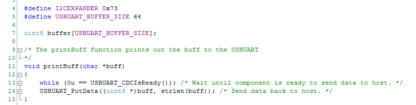
Original PSoC 5 Timer Implementation (0-testTimer1)
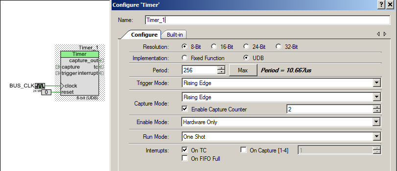
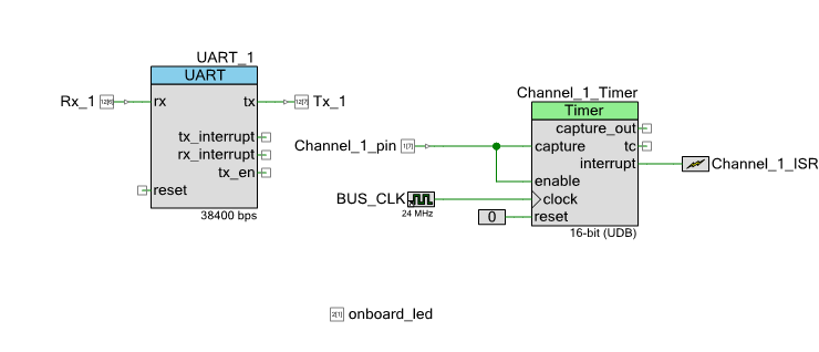
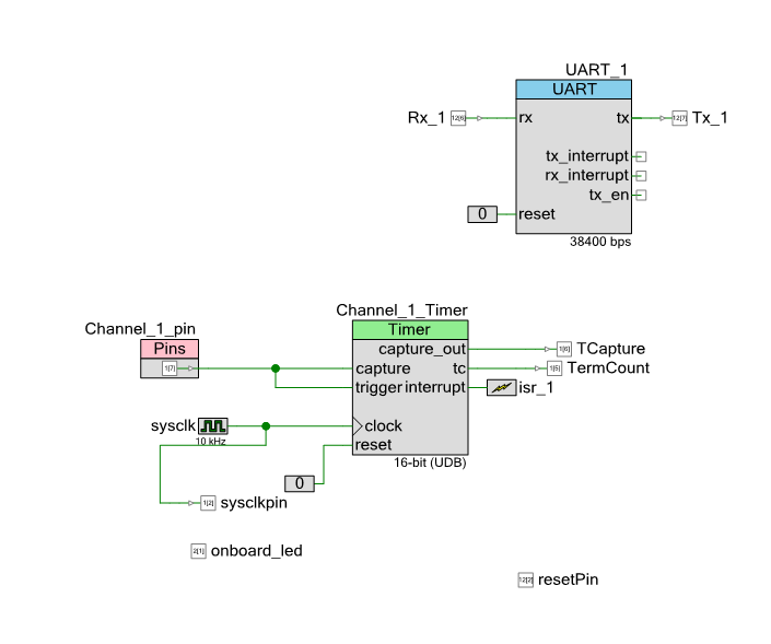
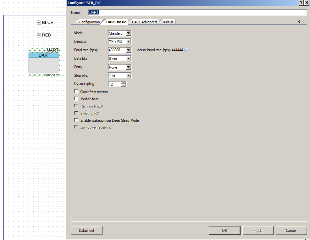
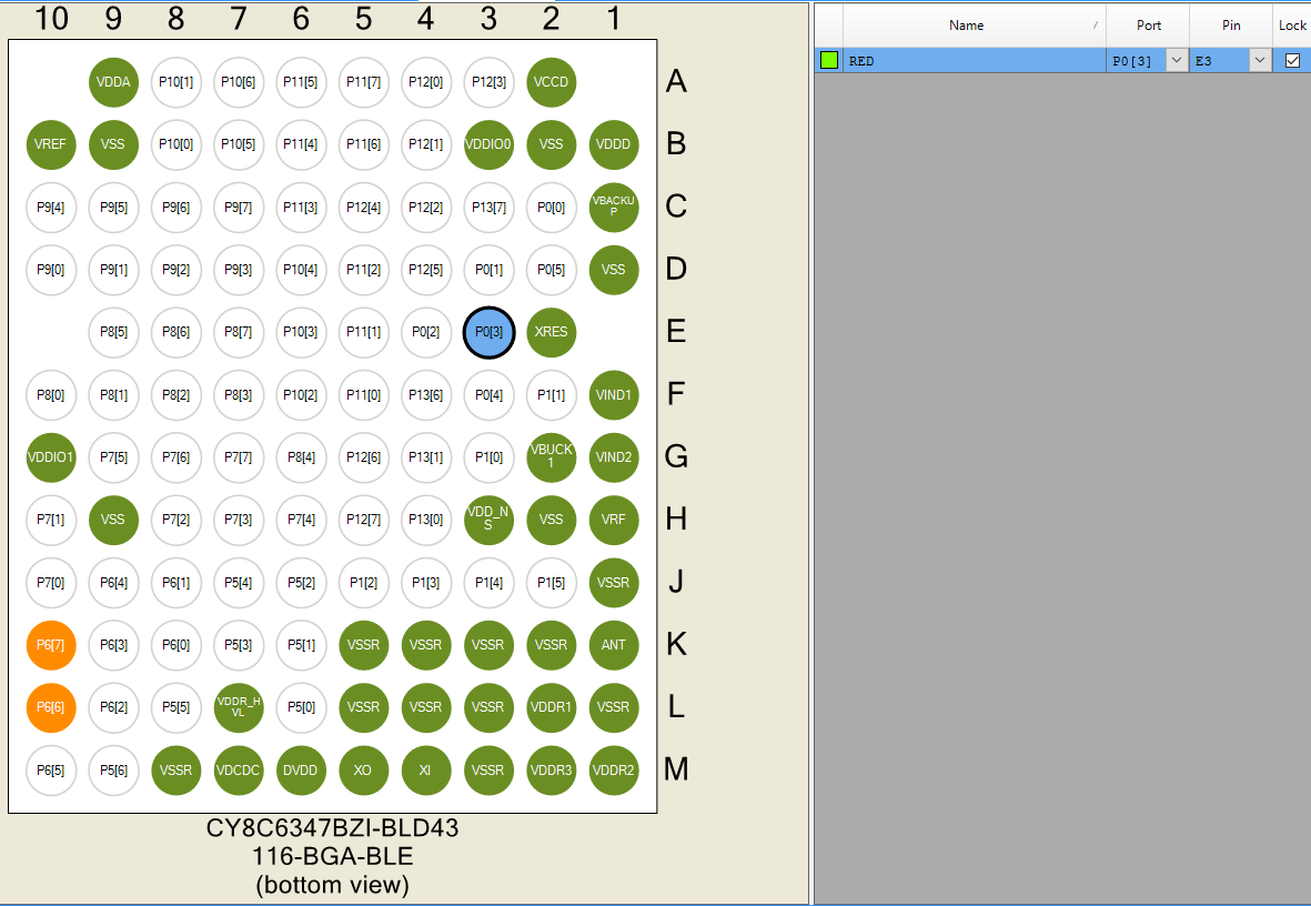
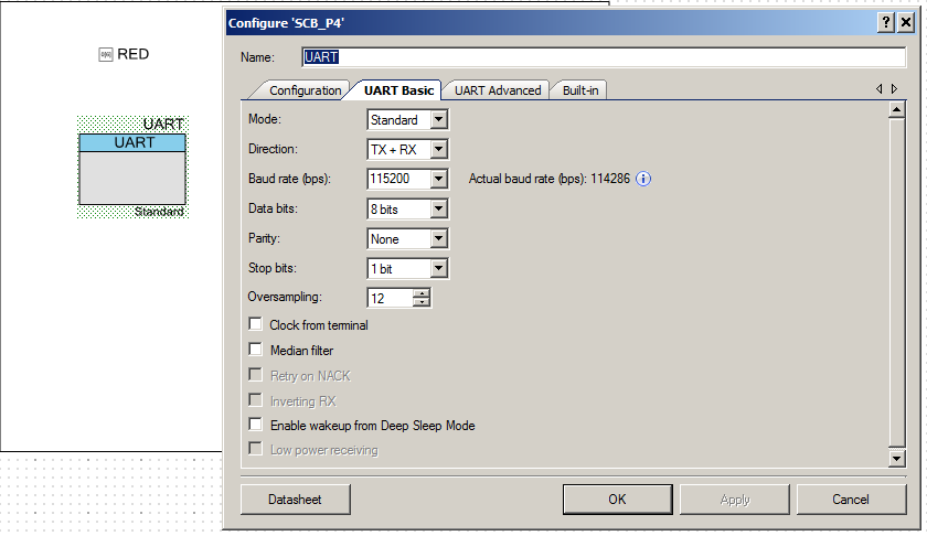
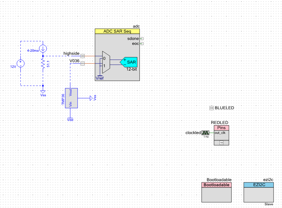
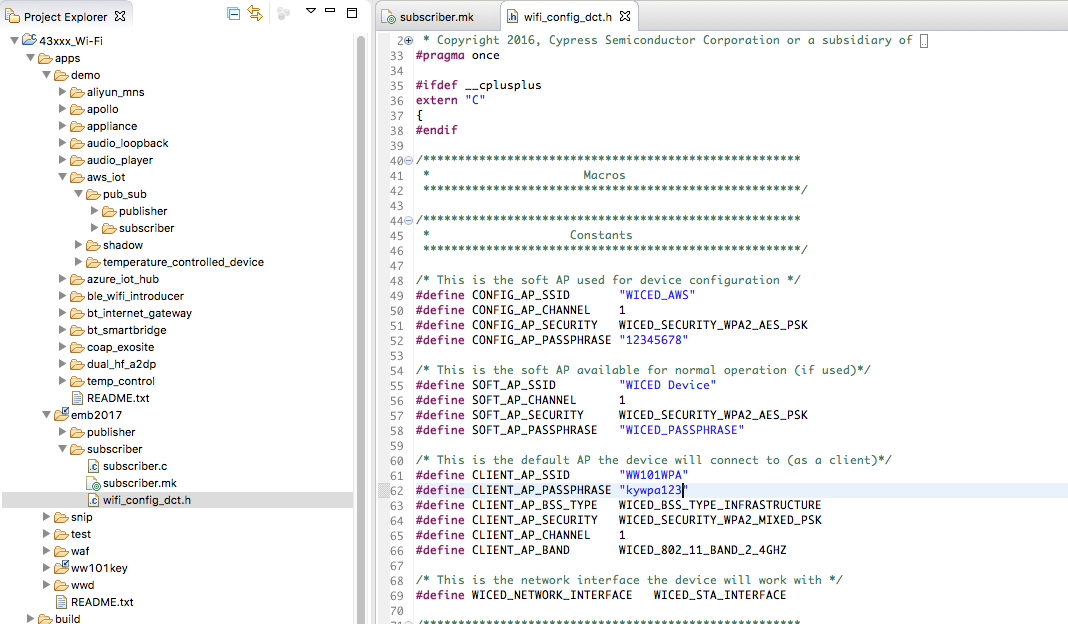
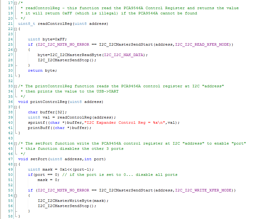
Here is the original project that was sent to me. It is simply a UART to talk to the PC and a PSoC 5 Timer that is setup to capture on the falling edge of capture. That is simple enough. The PSoC 5 timer is enabled when the Channel_1_pin signal is high. The idea is that the PSoC 5 timer will trigger an interrupt when the capture event occurs or when the terminal count (0) is reached. Then you will be able to calculate the number of clock ticks and therefore the length of the pulse. This is generally the right idea.
Then the firmware. It has an ISR to service interrupts from the Timer. The idea being there is a global variable called “Channel_1_Count” which hold the most recent pulse width which is calculated when the capture event occurs.
#include "project.h"
#include <stdlib.h>
#include <math.h>
#include <stdio.h>

#define Ch1Period	55555									//	Period for Channel_1_Timer

char Serial_Command;
char StringToPrint[90];
volatile uint32 Channel_1_Count;

CY_ISR(Channel_1_ISR_Handler)
{
uint8 InterruptCause;										//	Set by status register read
    Channel_1_Count = Channel_1_Timer_ReadPeriod();
    onboard_led_Write(~onboard_led_Read());					//	Indicate interrupt
	Channel_1_Timer_ClearFIFO();							//	Remove any additional captures
    InterruptCIe = Channel_1_Timer_ReadStatusRegister();	//	Read and clear interrupt status
	if(InterruptCause & Channel_1_Timer_STATUS_TC)			//	Did we overflow??
	{
		Channel_1_Count = 0;								//	Error, no falling edge on signal
		return;												//	No further action required
	}
	Channel_1_Timer_Stop();									//	Halt timer
    Channel_1_Timer_WriteCounter(Ch1Period);				//	Rewrite counter for next cycle
	Channel_1_Timer_Start();								//	Restart Timer
}

int main(void)
{
    CyGlobalIntEnable; /* Enable global interrupts. */

    UART_1_Start();
    Channel_1_Timer_Start();
	Channel_1_ISR_StartEx(Channel_1_ISR_Handler);
    for(;;)
    {
     Serial_Command = UART_1_GetChar();
        if(Serial_Command == 's'){
        sprintf(StringToPrint,"Channel1 capture is %ld\n\r",Channel_1_Count);
        UART_1_PutString(StringToPrint);
        }
    }
}
When I first looked at the design I notice several possible issues, a couple of style issues, a few little bugs and two big bugs:
- (Style) including stdlib.h and math.h is not required
- (Style) On line 6 putting a // comment on a #define line is asking for trouble
- (Style) On line 6 there should be () surrounding a numerical value for a #define
- (little bug) On line 6 the period is actually 55554 (the Period gets set to Period – 1 because of the 0 in the counter)
- (Style) Line 8-9 the Serial_Command and StringToPrint are global when they are actually local to the main function
- (little bug) Lines 8-9-10 The three variables should be static (restricted scope to this file)
- (little bug) the reset pin on the UART is left hanging (PSoC Creator ties it to 0… so you get lucky)
- (bug) Line 15 – ReadPeriod will always return 55554 (the value of the period as set in the component customizer), this was probably meant to be ReadCounter()
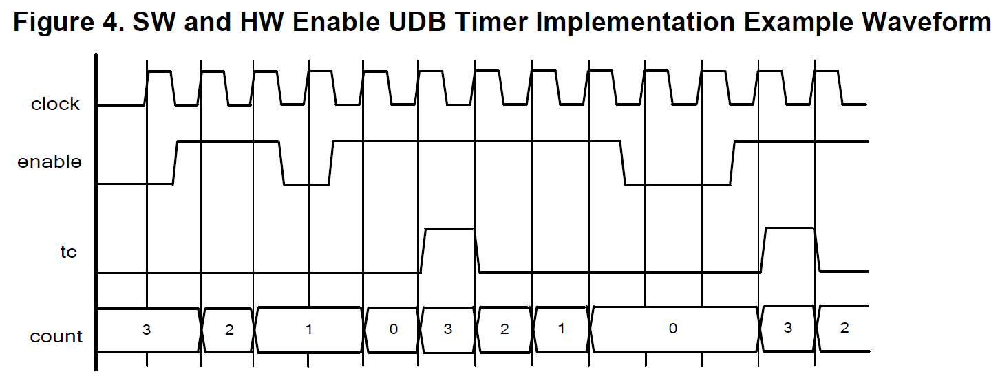
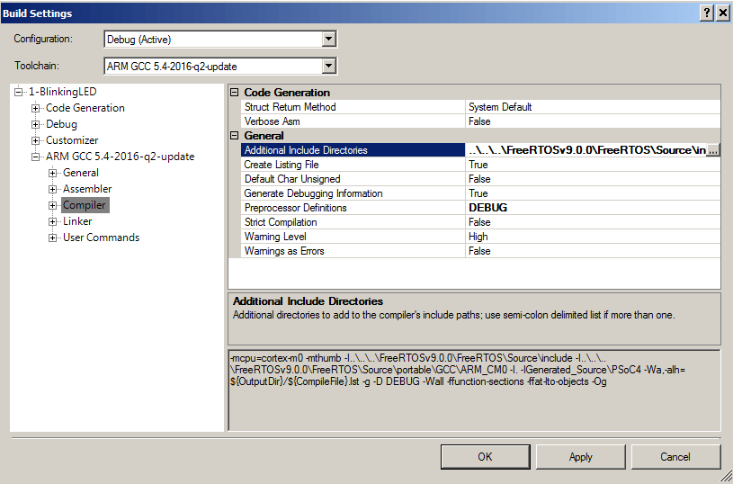
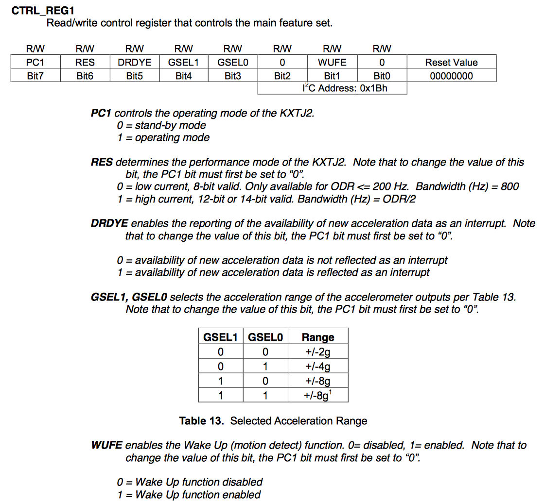
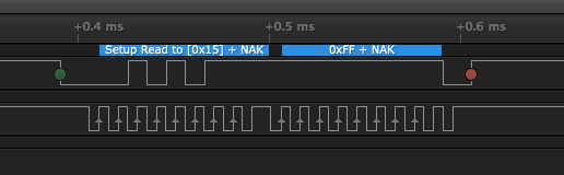
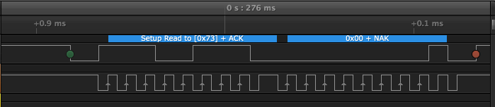
- (bug) disabling the PSoC 5 Timer with the input capture means the PSoC 5 Timer will never generate the interrupt until the enable is de-asserted. The picture below (from the timer datasheet) is a perfect example of the problem.
EDIT: I got a comment from Bob Marlowe who made an excellent point in the comment section. Specifically, when I moved the two global variables Serial_Command and StringToPrint to the local scope, that changed their allocation to “automatic”. In this case it doesn’t matter if the they are allocated on the stack or in the data/bss segment as the RAM usage is exactly the same. BUT as he pointed out, it can be very difficult to debug if you overflow the stack. In this case I could have controlled the scope by moving them local to main and controlled their allocation by declaring them as static. This would have solved the scope problem and simplified the allocation issue.
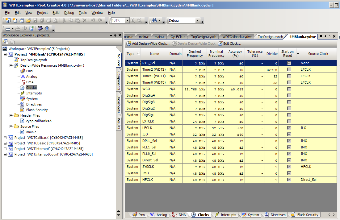
Software Solution (1-testTimer1) with PSoC 5 Timer
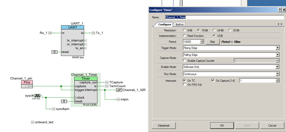
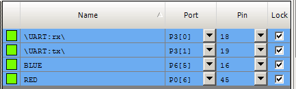
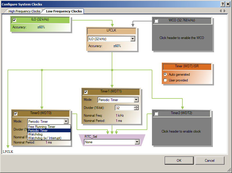
I started by building a solution that was as close as possible to the original design. The first thing that I did was add pins to all of the terminals on the PSoC 5 Timer so that I could attach a logic analyzer to it to see exactly what was happening. I then fixed the problem with the enable by switching from using “enable” to using “trigger”. The trigger input holds the counter at the same value until the trigger event occurs. You can see in the component customizer that I set it to “trigger”, also known as start counting, on a rising edge. Then capture on a falling edge.
The next thing thing that I did was move the input clock to 1000 khz aka 1 Mhz. This means that each clock is 1 microsecond. This makes all of the math easier. The original configuration was 24 Mhz which meant each clock cycle was 41 ns which is not a very useful number for my brain to figure out.
The final thing that I did to the schematic is make the “Channel_1_pin” an input/output pin. As I was sitting on the couch semi-watching basketball, I didn’t have a signal generator handy. What this allowed me to do was “trigger” the PSoC 5 Timer by writing the Channel_1_pin from the firmware.
Next I made a few changes to the firmware.
First, I moved the intFlag (which he had originally called InterruptCause outside of the ISR into a global variable so that I could keep track of what it was (and look at it again)
Then I made a few little changes to the interrupt service routine. First, I calculated the actual width of the pulse by subtracting it from the PSoC 5 Timer period (line 16). Then on Line 22-23 I stoped the PSoC 5 Timer and then set it up for the next go round.
Next, I changed the UART startup to send the VT100 escape codes to clear the screen and move the cursor to the top left.
Finally I updated the main block. I put in a “switch” block on lines 40-76 that allowed me to type different commands on the serial terminal to get the project to do different things. For instance I created a way to generate input signals by press ‘t’ and ‘y’. ‘t’ generates a 1234 uS pulse by writing a 1, doing a delay, then writing a 0 to Channel_1_pin. I knew that this should generate a “capture” event. ‘y’ generates an illegal pulses of 12 ms using the same technique. That wide pulse generates a “TC” on the timer. These two keys allowed me to test the program.
The last bit of code on lines 78-84 print out the value of the width of the pulse, then turn the timer back on.
#include "project.h"
#include <stdio.h>
// Period for Channel_1_Timer
#define Ch1Period (9999)
static volatile uint32 Channel_1_Count;
static int intFlag = 0;
CY_ISR(Channel_1_ISR_Handler)
{
intFlag = Channel_1_Timer_ReadStatusRegister(); // Read and clear interrupt status
onboard_led_Write(~onboard_led_Read());
if(intFlag & Channel_1_Timer_STATUS_CAPTURE)
Channel_1_Count = Ch1Period - Channel_1_Timer_ReadCapture();
if(intFlag & Channel_1_Timer_STATUS_TC) // Did we overflow??
Channel_1_Count = 0;
Channel_1_Timer_Stop(); // stop and setup for next round
Channel_1_Timer_WriteCounter(Ch1Period); // Rewrite counter for next cycle
}
int main(void)
{
char Serial_Command;
char StringToPrint[90];
CyGlobalIntEnable;
UART_1_Start();
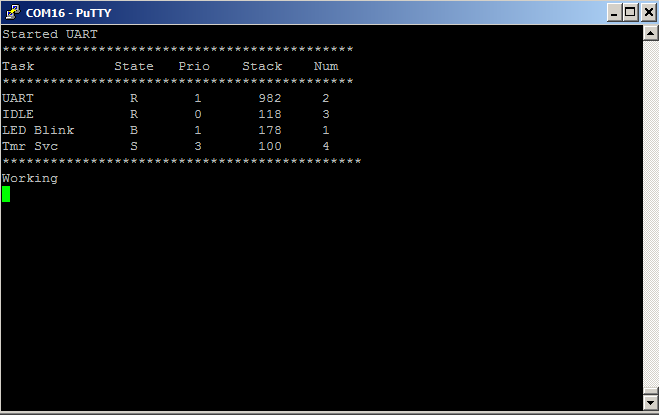
UART_1_PutString("\033[2J\033[HStarted\n"); // Clear the screen
Channel_1_ISR_StartEx(Channel_1_ISR_Handler);
Channel_1_Timer_Start();
for(;;)
{
Serial_Command = UART_1_GetChar();
switch(Serial_Command)
{
case 's':
sprintf(StringToPrint,"Channel1 capture is %ld\n",Ch1Period-Channel_1_Count);
UART_1_PutString(StringToPrint);
break;
case 't':
UART_1_PutString("Trigger 1.23 ms Edge\n");
Channel_1_pin_Write(1);
CyDelayUs(1230);
Channel_1_pin_Write(0);
break;
case 'y':
UART_1_PutString("Trigger 12ms Overflow \n");
Channel_1_pin_Write(1);
CyDelayUs(12000);
Channel_1_pin_Write(0);
break;
int counter;
case 'c':
counter = Channel_1_Timer_ReadCounter();
sprintf(StringToPrint,"Channel1 counter is %d\n",counter);
UART_1_PutString(StringToPrint);
break;
case 'q':
Channel_1_Timer_Stop(); // Halt timer
break;
case 'w':
Channel_1_Timer_Stop(); // Halt timer
Channel_1_Timer_WriteCounter(Ch1Period); // Rewrite counter for next cycle
Channel_1_Timer_Start(); // Restart Timer
break;
}
if(intFlag) // There was an event... what happened?
{
sprintf(StringToPrint,"Channel1 %s Time= %ld\n",(intFlag & Channel_1_Timer_STATUS_CAPTURE)?"Capture":"Overflow", Channel_1_Count);
UART_1_PutString(StringToPrint);
intFlag = 0;
Channel_1_Timer_Start();
}
}
}
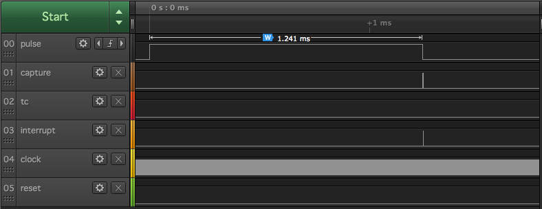
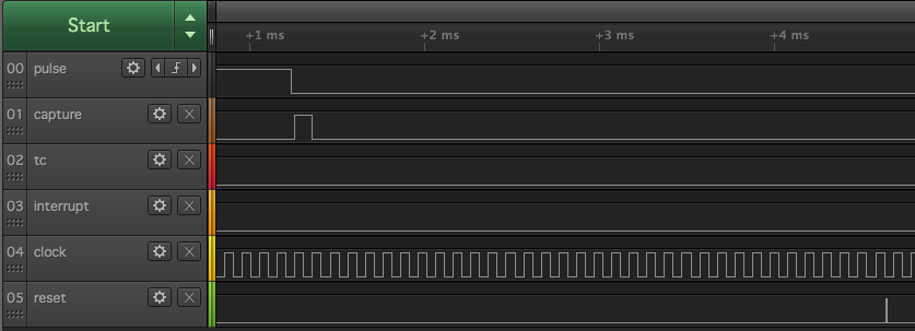
When you look at the capture event (by pressing ‘t’) this is what you see on the logic analyzer:
- A 1.241 wide pulse on “pulse” (pretty damn close to 1234 uS)
- A pulse on the “capture” flag
- A pulse in the “interrupt” pin
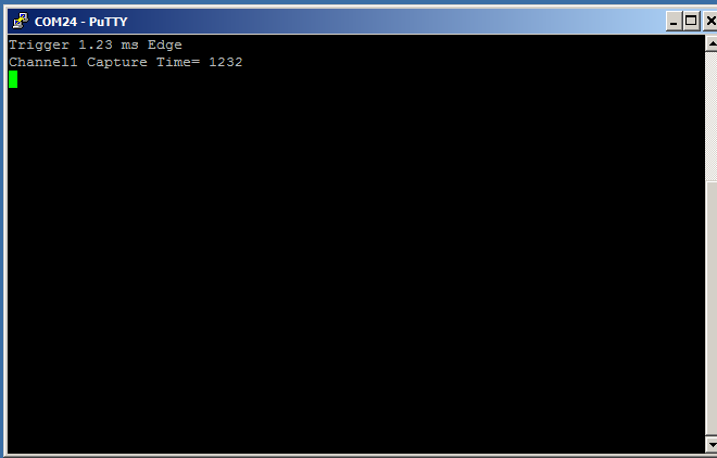
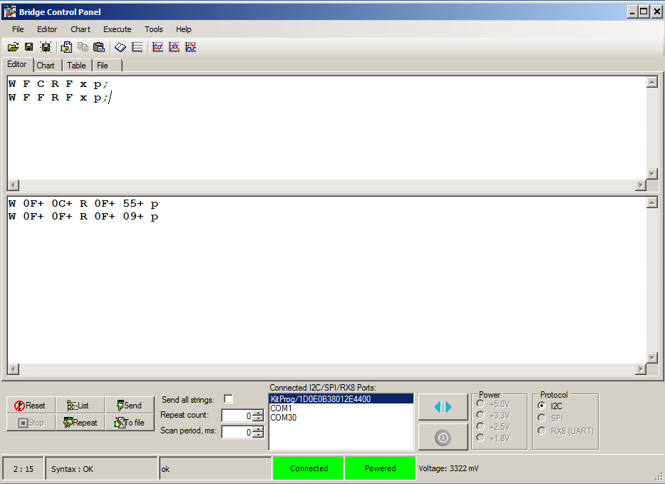
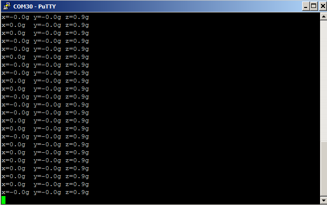
And the serial terminal says:
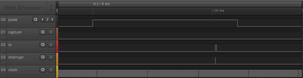
When you press ‘y’ to make a wide pulse, then look at the terminal count event on the logic analyzer you can see
- A 12ms wide pulse
- A pulse on the terminal count
- A pulse on the interrupt (indicating a terminal count)
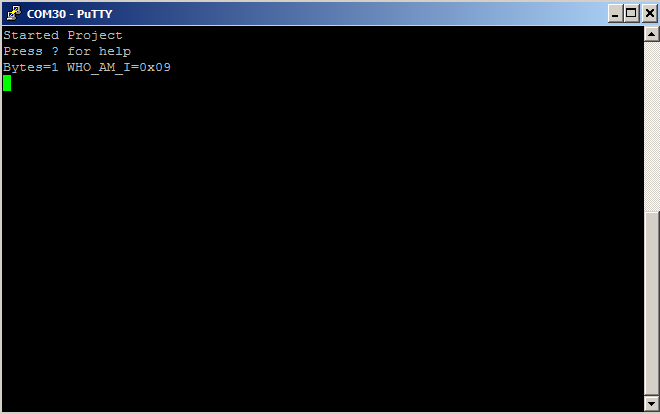
And the terminal program says the same thing
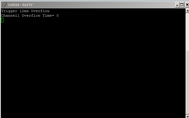
This is all good. The project seems to be working correctly.
Problem with PSoC 5 Timer & debug project (2-triggerDebug)
While I was working on fixing this program I was struggling with the loop not “stopping”. In other words, the timer kept running even though the interrupt had occurred. To figure this out I hooked up the logic analyzer again, and built a project to help debug it.
I suspected that I had a timing issue with my stopping/starting of the timer. To debug the problem I added a pin to the schematic called “resetPin”
Then I changed the ISR to not restart the Timer, but to wait until later for the start. I also added a “#define” to let me move the start/stop around in the code.
    #ifdef ISR_RESET
    resetPin_Write(1);
    #endif
    Channel_1_Timer_Stop();
    Channel_1_Timer_WriteCounter(100);

    #ifdef ISR_RESET
    Channel_1_Timer_Start();
    resetPin_Write(0);
    #endif
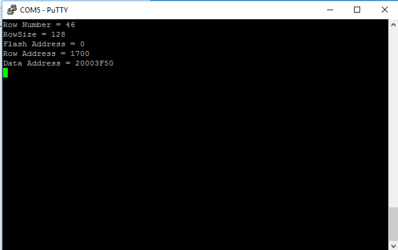
When it seemed like thing just kept going, this is what I got this:
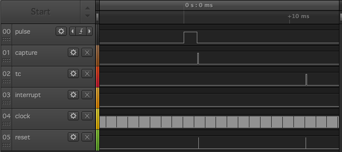
Or in zoomed in fashion:
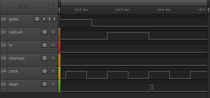
What I realized is that there needs to be a little bit of time between the capture event and the restart of the Timer block. When I moved the restart later in the code, outside of the ISR
      if(intFlag)  // If an event occurred print the value
        {
            sprintf(StringToPrint,"Int %d Counter= %ld\n",intFlag,Channel_1_Count);
            UART_1_PutString(StringToPrint);
            #ifndef ISR_RESET
            resetPin_Write(1);
            Channel_1_Timer_Start();
            resetPin_Write(0);
            #endif
            intFlag = 0;
        }
It was fixed. Notice that the “restart” happened a bunch of clock cycles later.
Hardware Solution (3-testTimer1-reset) using PSoC 5 Timer
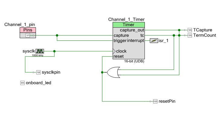
But, I didnt stop there. I was not a big fan of the software solution (which looks like Arduino), and I really hated the start/stop scheme that I was using. In order to fix this I wanted to try a mostly hardware reset scheme. The first schematic (called 3-testTimer1-reset-nonfunctional) had this attempt to reset the Timer based on the output or the capture || terminal count.
But this did not work because by the time you got to the ISR the block was reset and you had no value for the counter. To fix this I put a control register in to reset the system (this was Greg’s great idea)
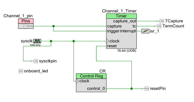
I used the “pulse” setting in the control register, which makes a 1 clock cycle wide pulse when you write a 1 to the register. This made the firmware a breeze. Here is the updated ISR with the control register write on line 9.
CY_ISR(isr_1_Handler)
{
    Channel_1_Count = Channel_1_Timer_ReadCounter();
    intFlag = Channel_1_Timer_ReadStatusRegister();

    onboard_led_Write(~onboard_led_Read());
    CR_Write(1);

    if(intFlag & Channel_1_Timer_STATUS_TC)
        Channel_1_Count = 0;

}
I sent these projects to the customer thinking that I was done.
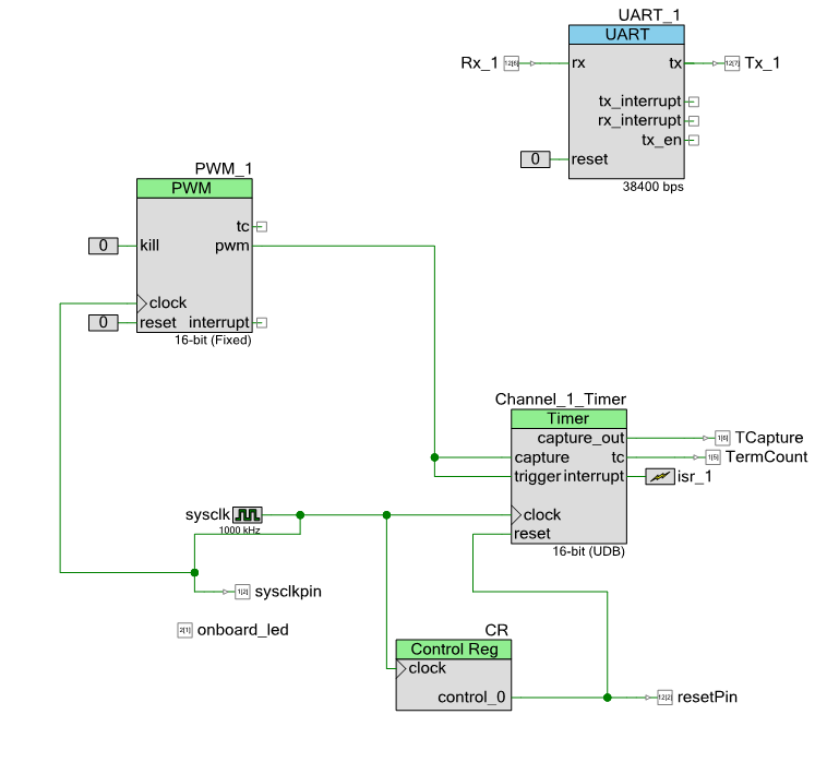
Driving the PSoC 5 Timer System with a PWM (4-testTimer1-reset-pwm)
But, the next morning he told me that he attached a pulse to the pin and it wasn’t working. I was pretty sure that it worked, but I decided to add a pulse source to the system to be sure. To do this I added a PWM to drive the Timer, and a bit of firmware to let me change the width of the pulse. Here is the updated schematic. In it, you can see the new “PWM_1” which I have setup with a period of 5ms and a variable width (amazingly enough PWMs are very good at that). Then in the firmware I can change the compare value of the PWM to change the width of the pulse that I am measuring.
Here is the section of the firmware that lets me change the width of the pulse:
            case 'k':
                PWM_1_WriteCompare(PWM_1_ReadCompare() - 100);
            break;

            case 'l':
                PWM_1_WriteCompare(PWM_1_ReadCompare() + 100);
            break;
I like this because I can change the width of the pulse by 100us by clicking k to decrease and clicking l to increase. I tested this and it also worked well… so I am not sure exactly why his version didn’t work. But I sent it on.
A connection of the input –> output (5-testTimer1-reset-pwm-external)
Then again, I got an email that it wasn’t working. I thought that maybe it was that I wired the PWM directly to the Timer. So, in order to fix this I added that wire on the outside of the chip. Here is the updated schematic. I thought that while I was working on it, I would make the calculated pulse width coming into the system also go to an output PWM. In other words, I calculate the width of the input pulse, then drive that to another PWM with an output. Here is the schematic:
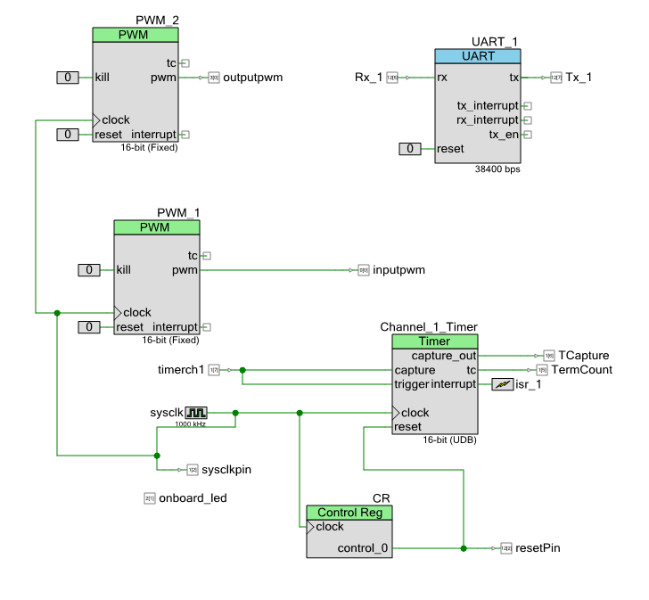
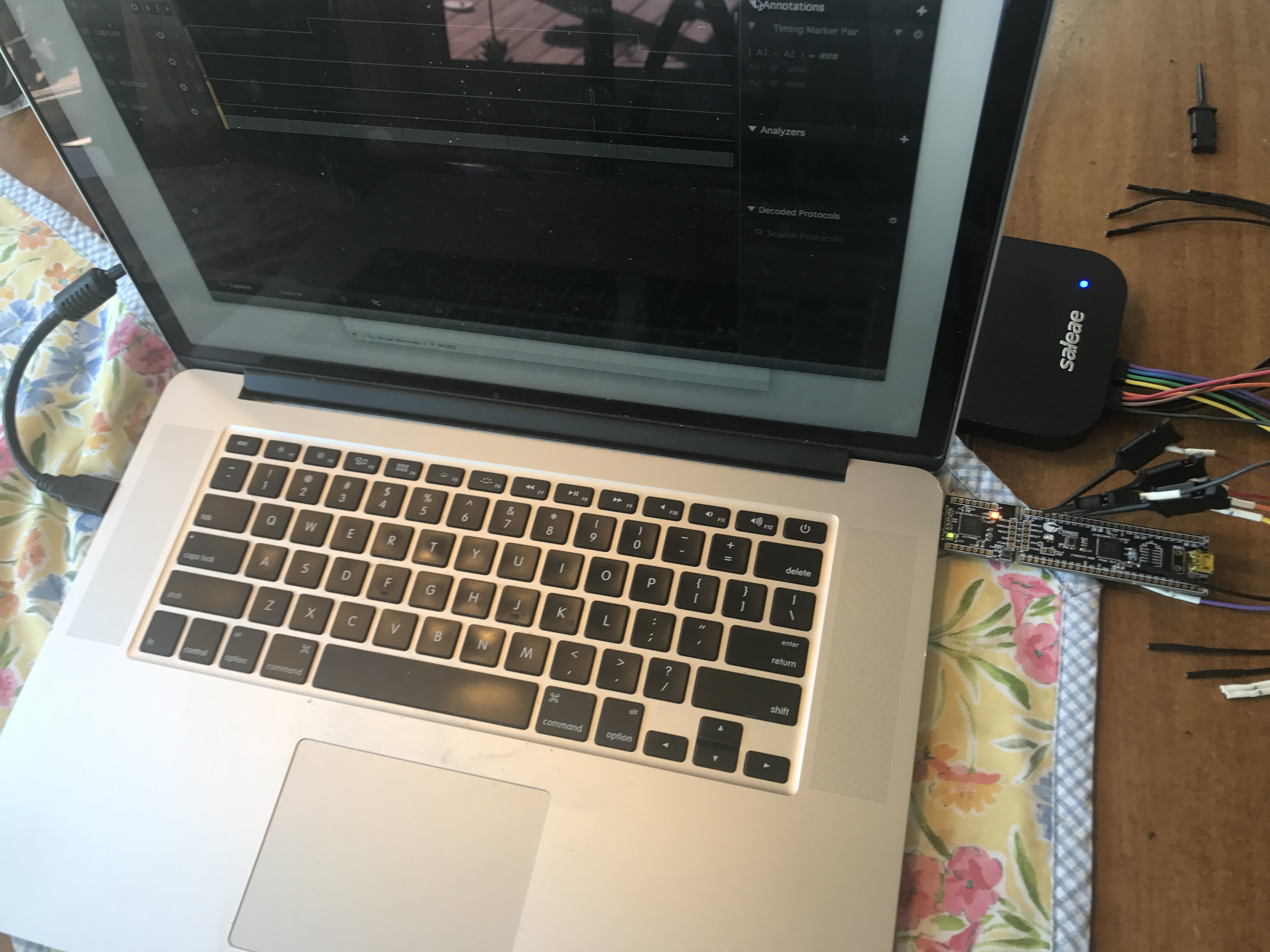
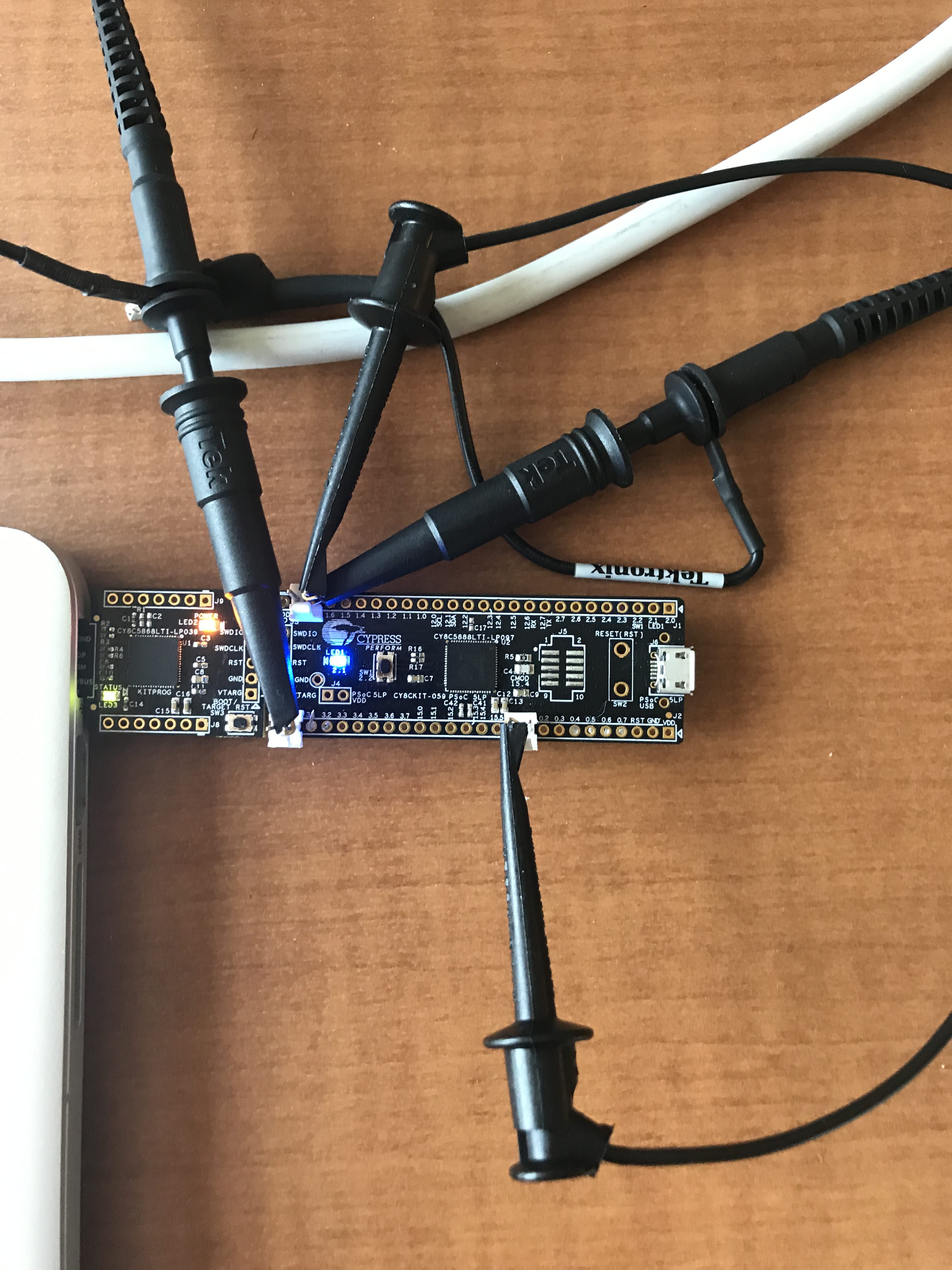
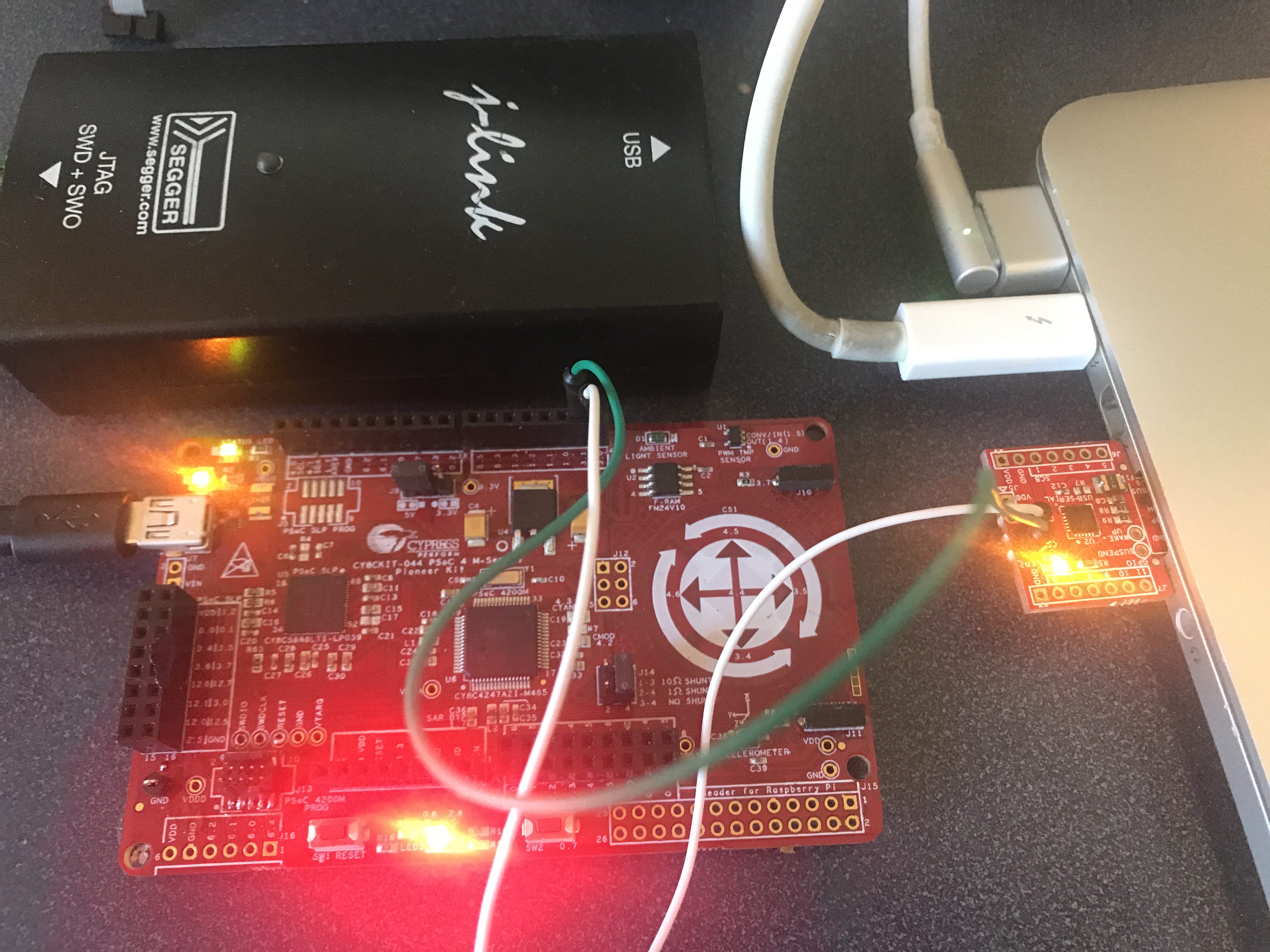
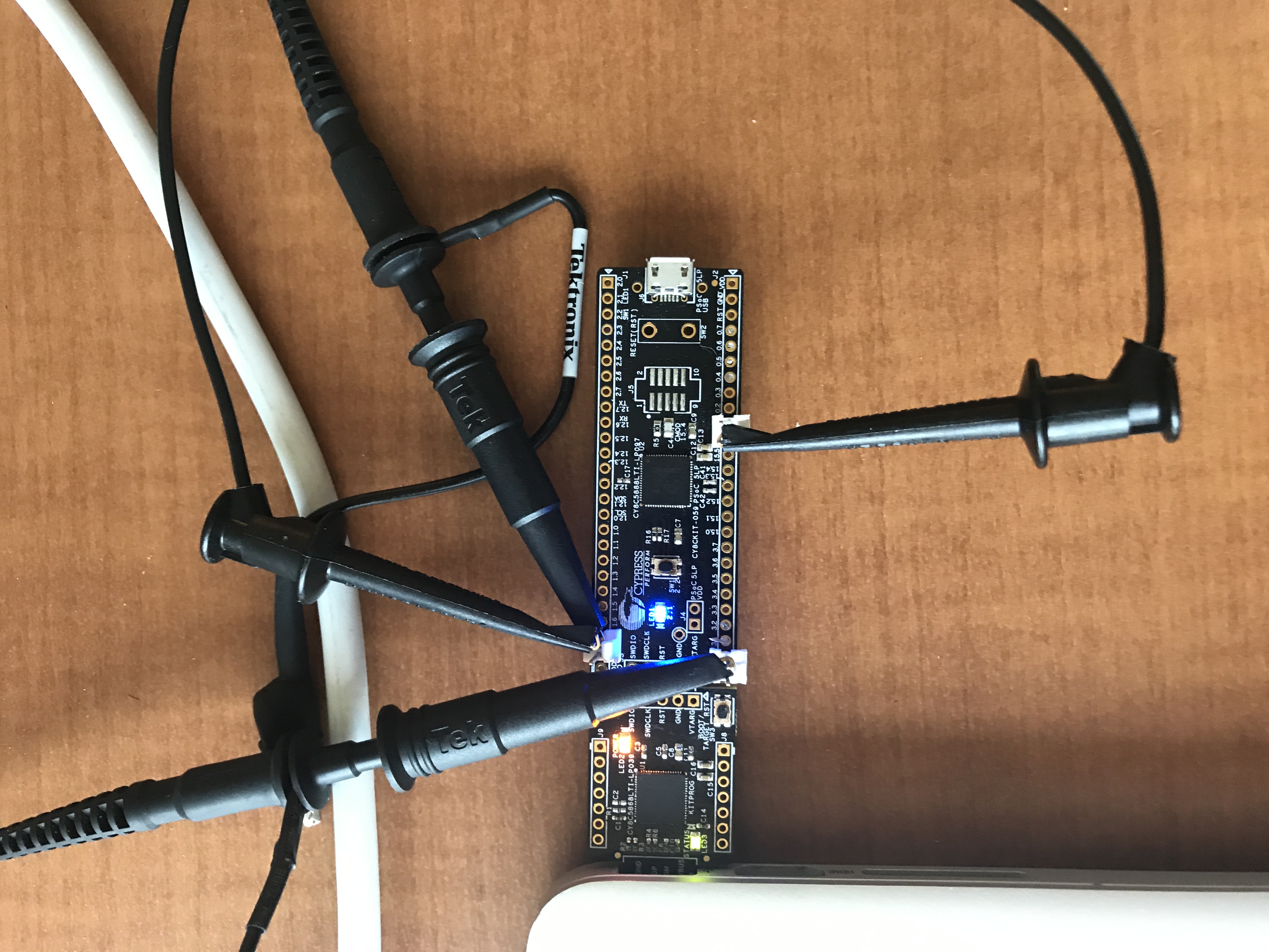
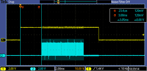
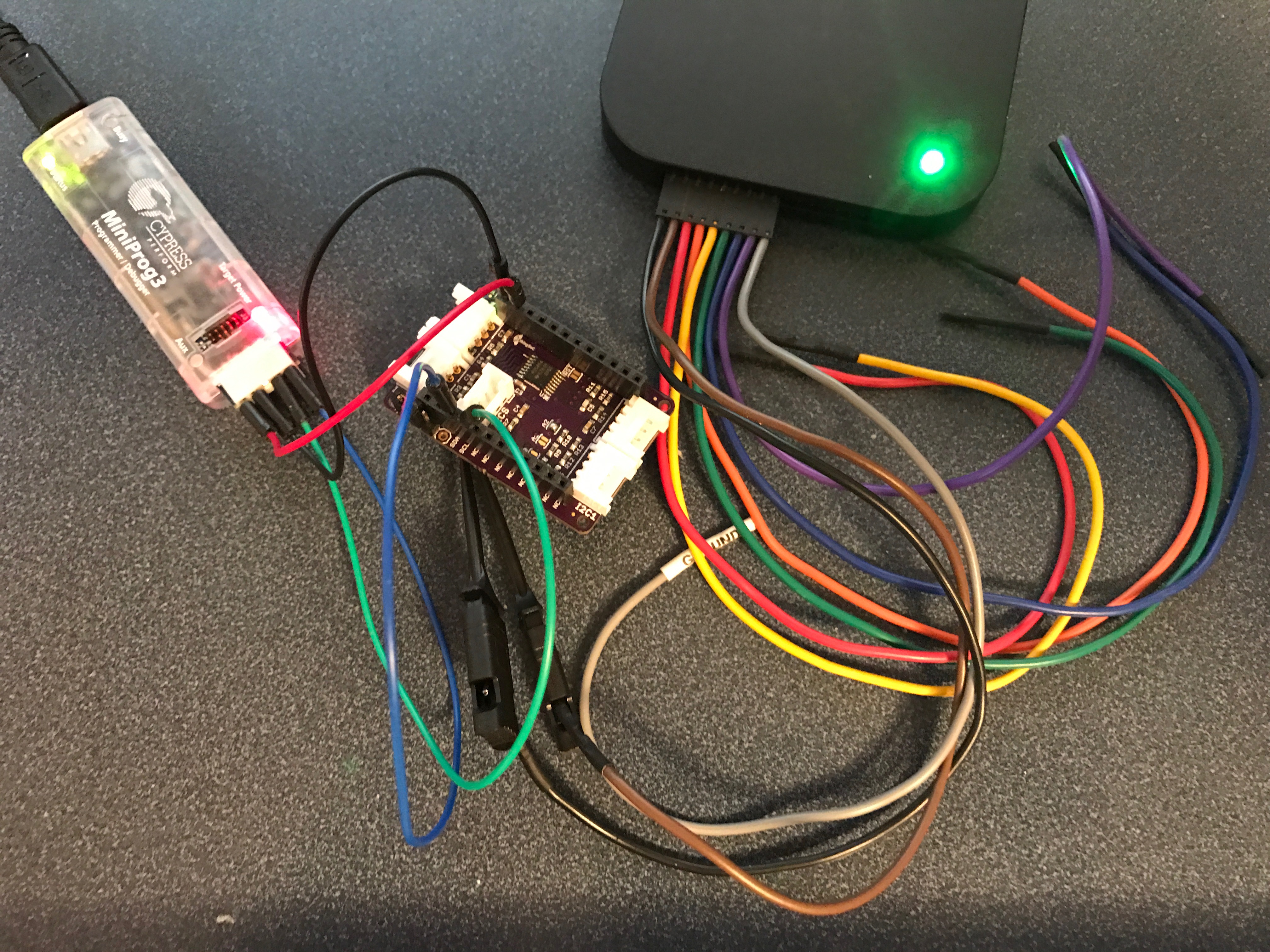
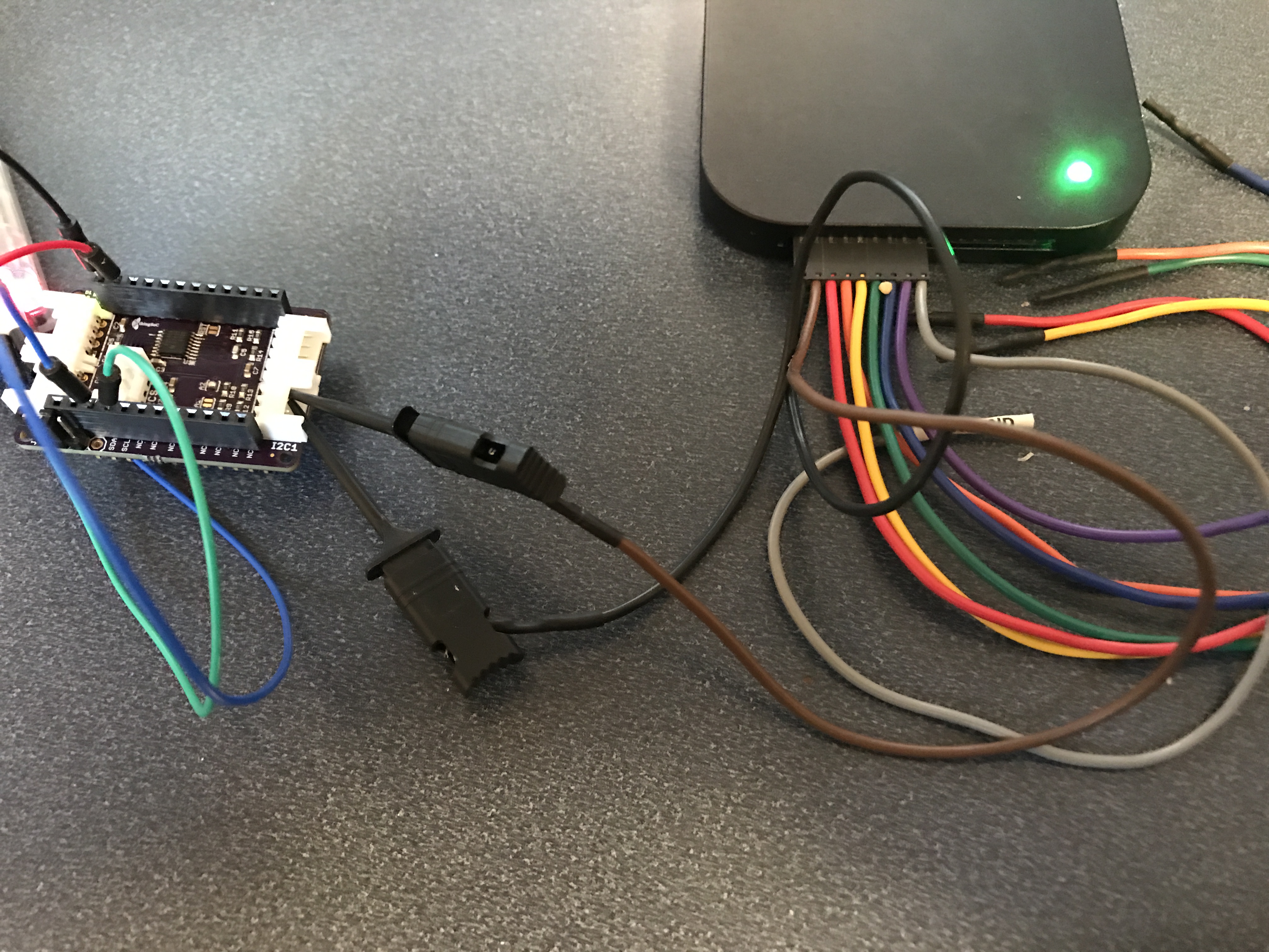
To test the system I attached wires to my oscilloscope and a wire between the pins of the PWM and the PSoC 5 Timer (the black wire)
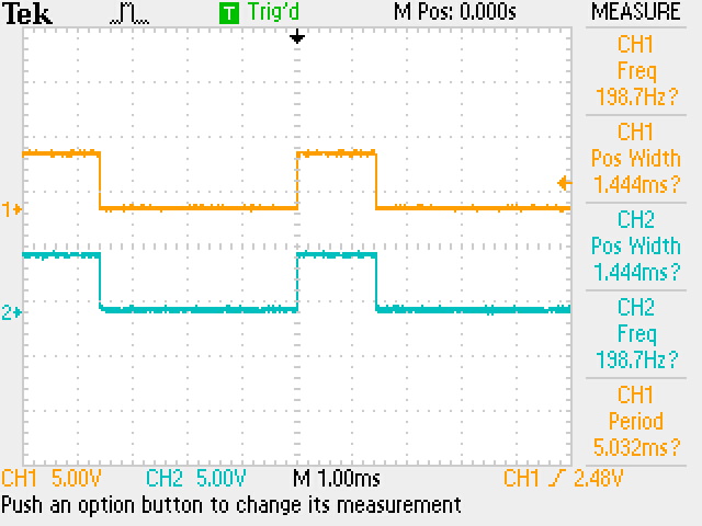
 And here is the output on the oscilloscope. CH1 is the input PWM and CH2 is the output PWM. You can see that it tracks exactly.
I sent this project to the customer, and this time I got a message that it was working!!! Excellent! And he said that the problem was a programming problem from before. That was good as it meant all of the other projects worked.
Comments and Future
First, thank you to Sumat for having a good sense of humor working with me. It turns out that this isn’t a work project but something he is doing for fun.
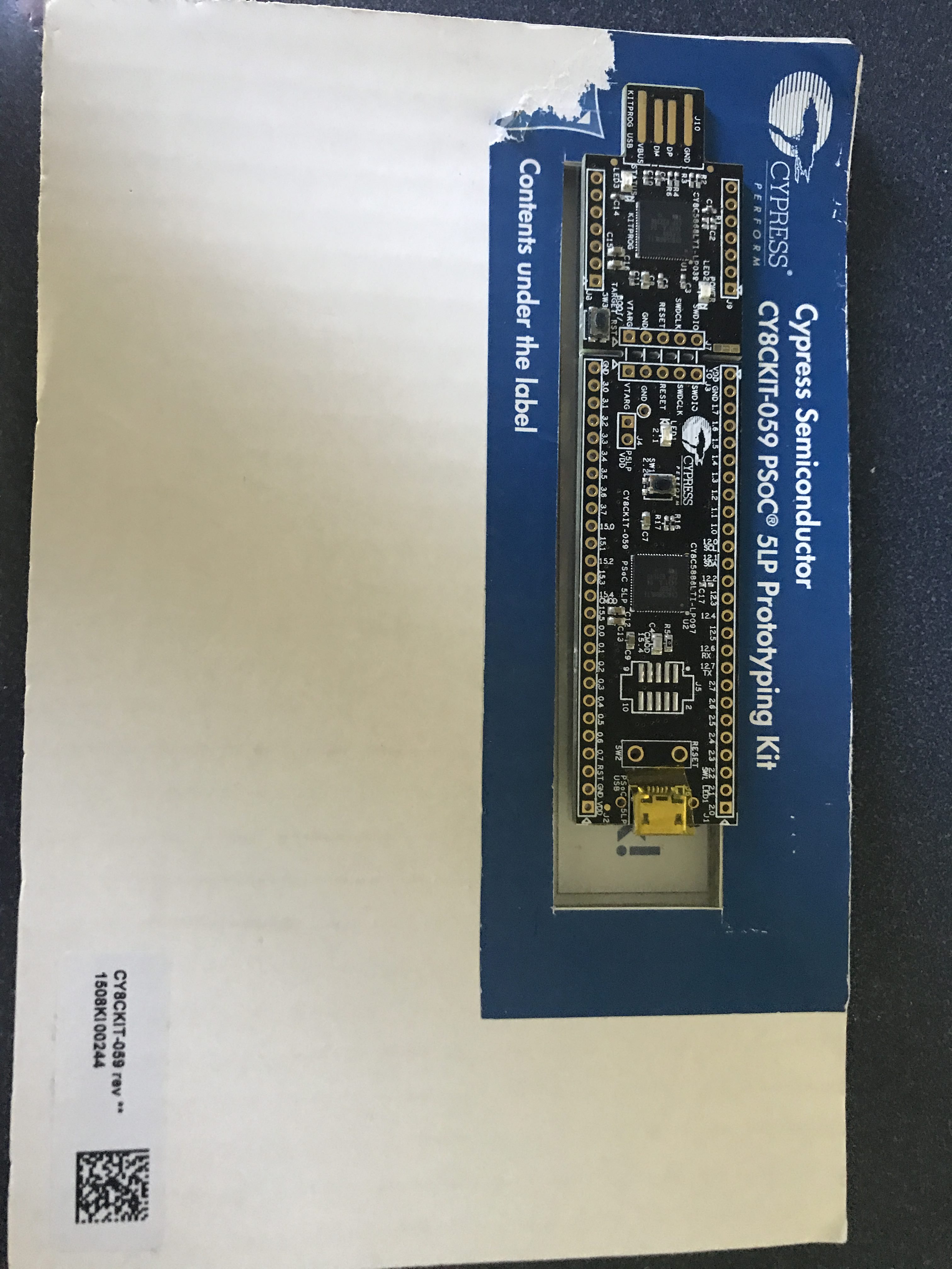
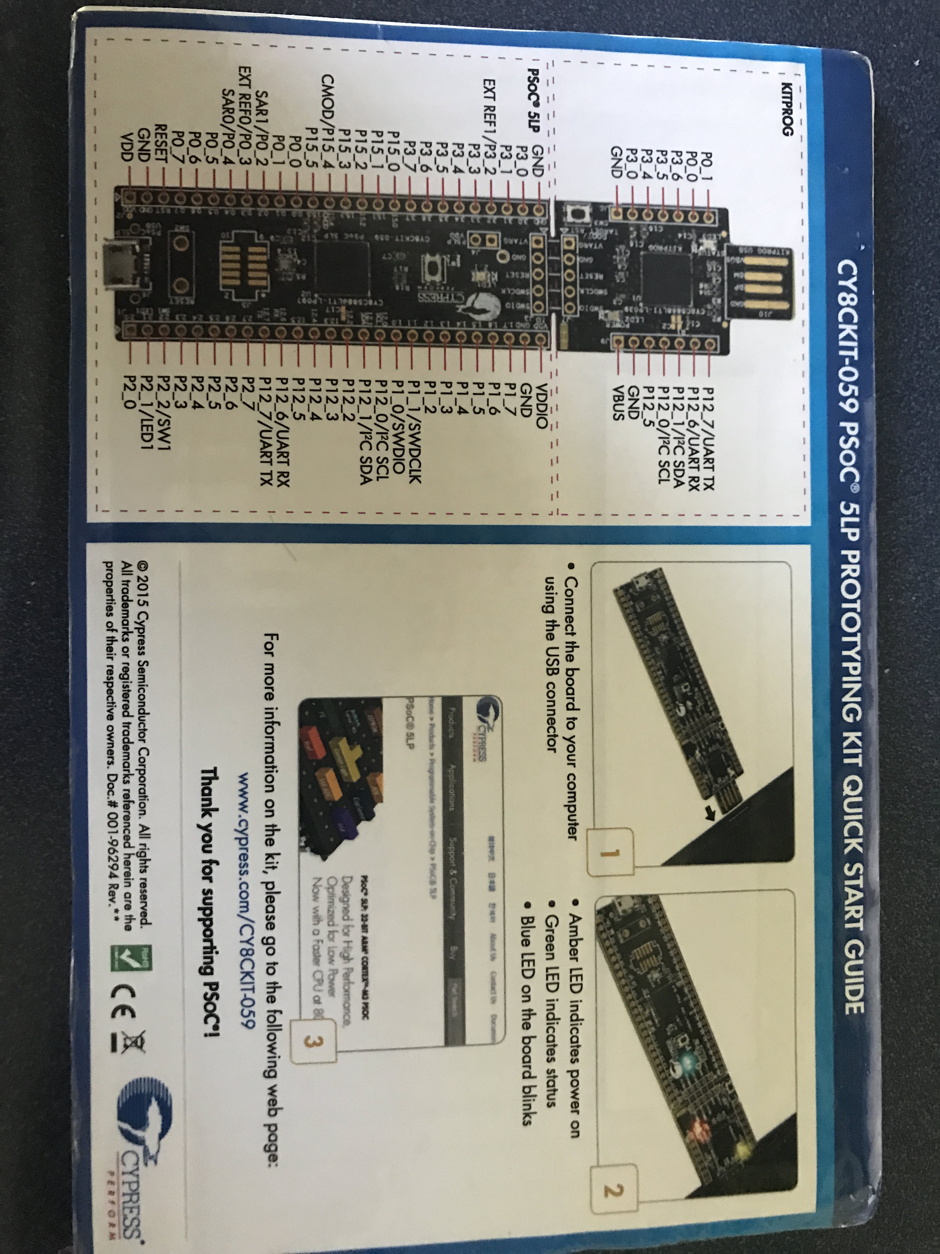
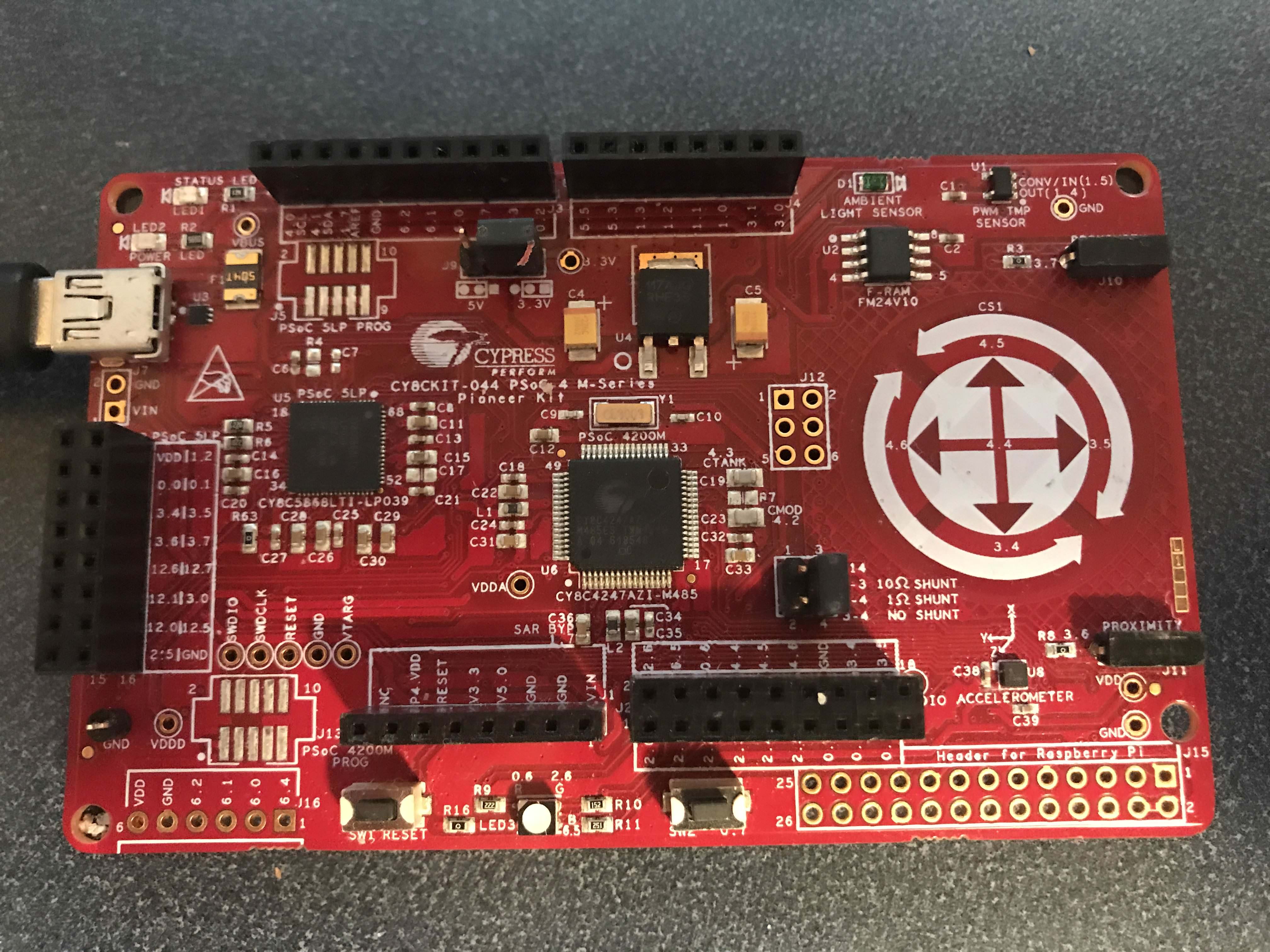
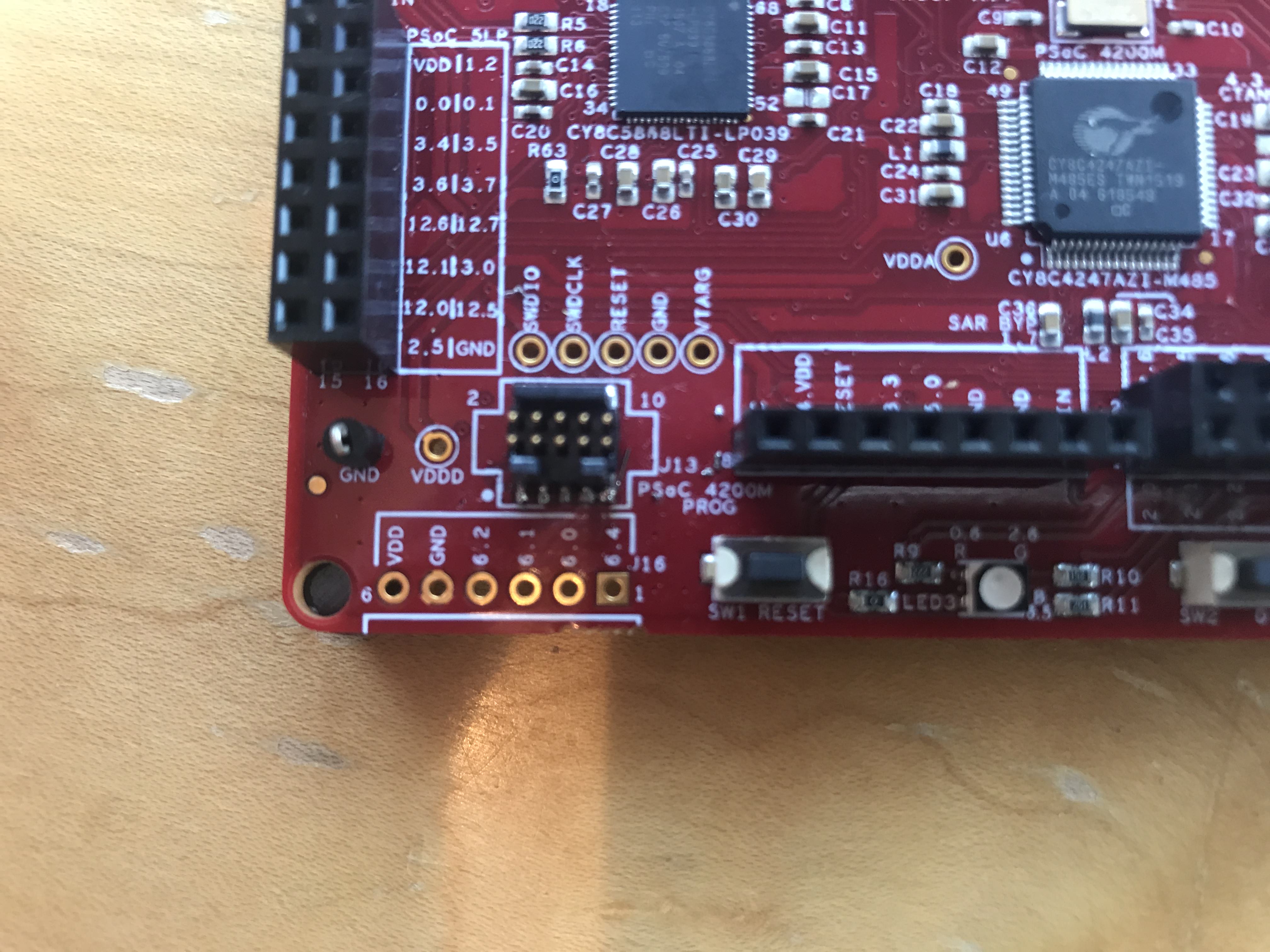
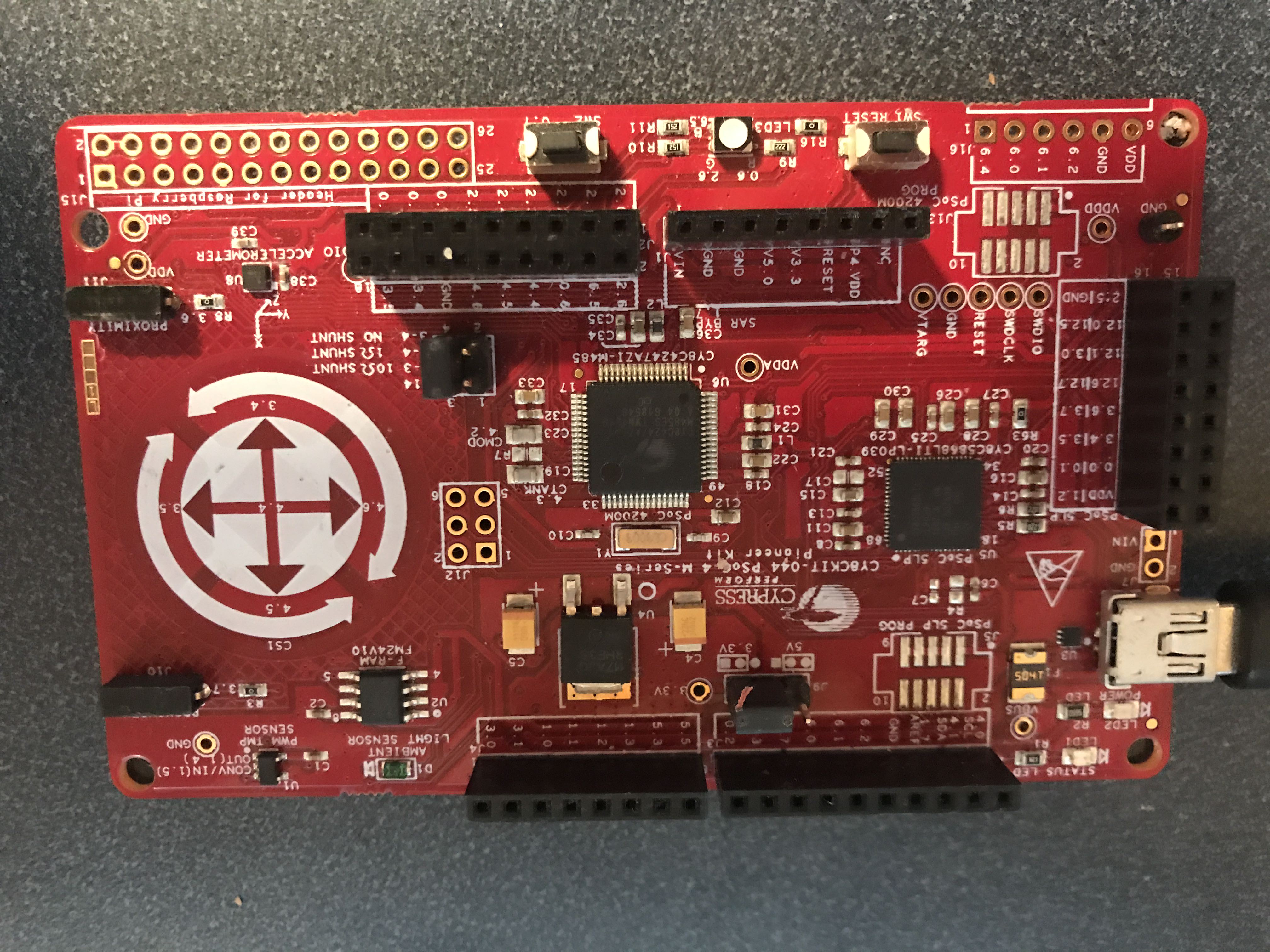
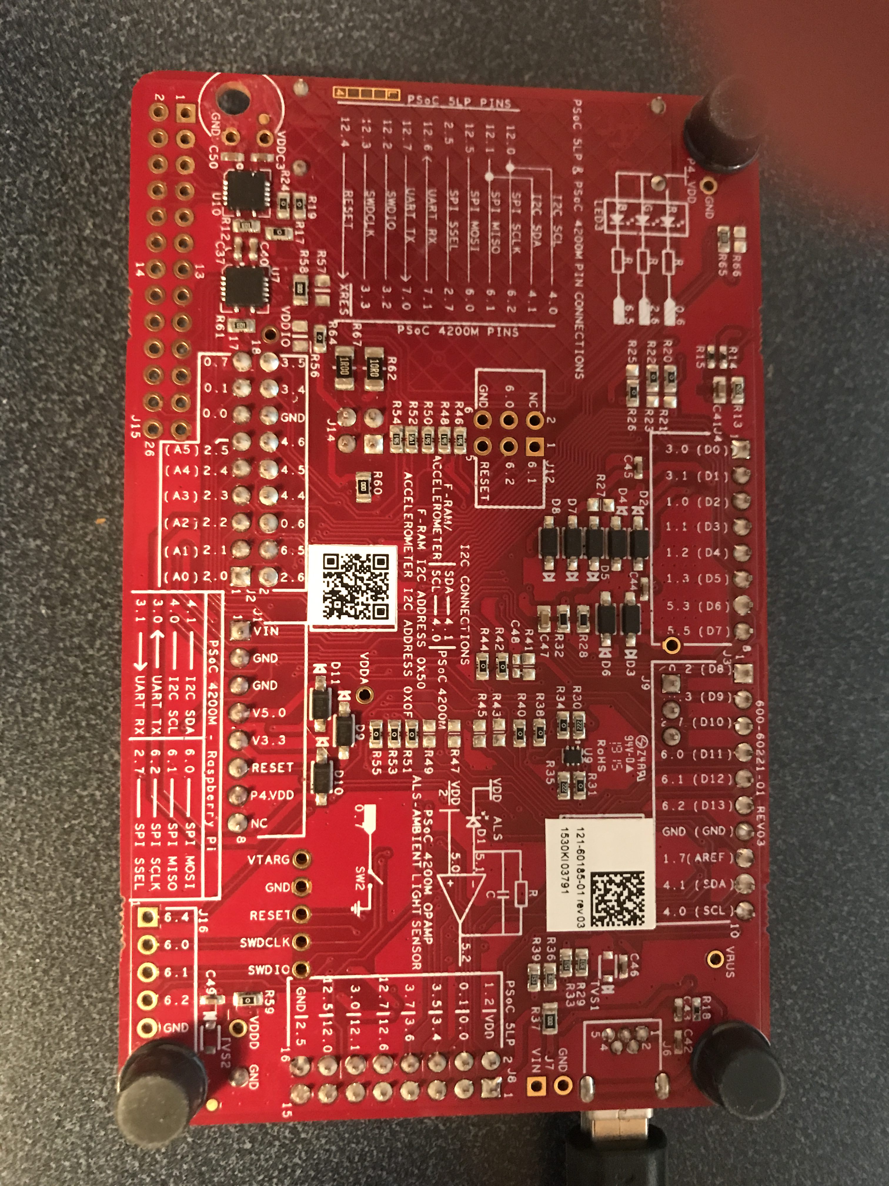
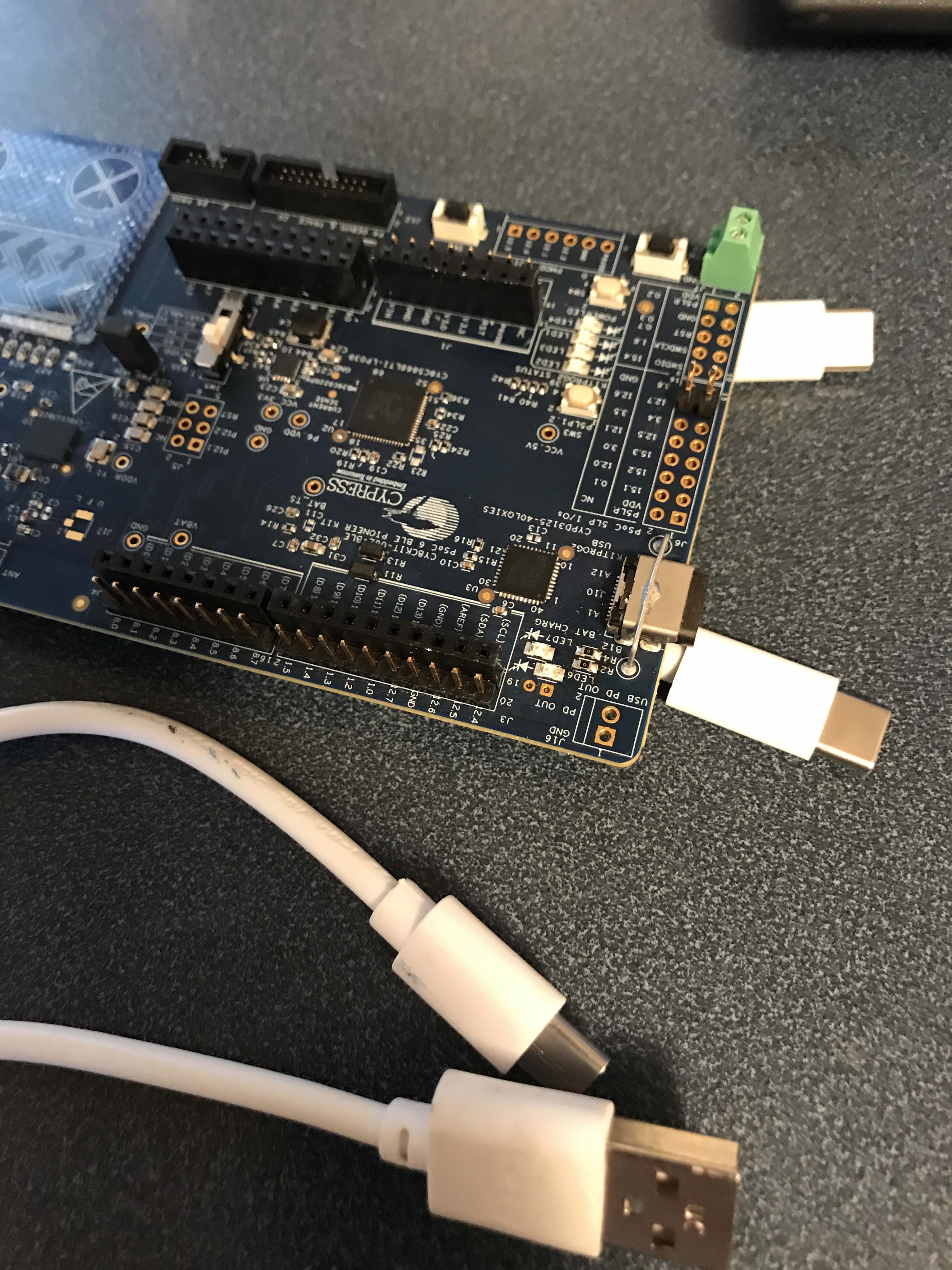
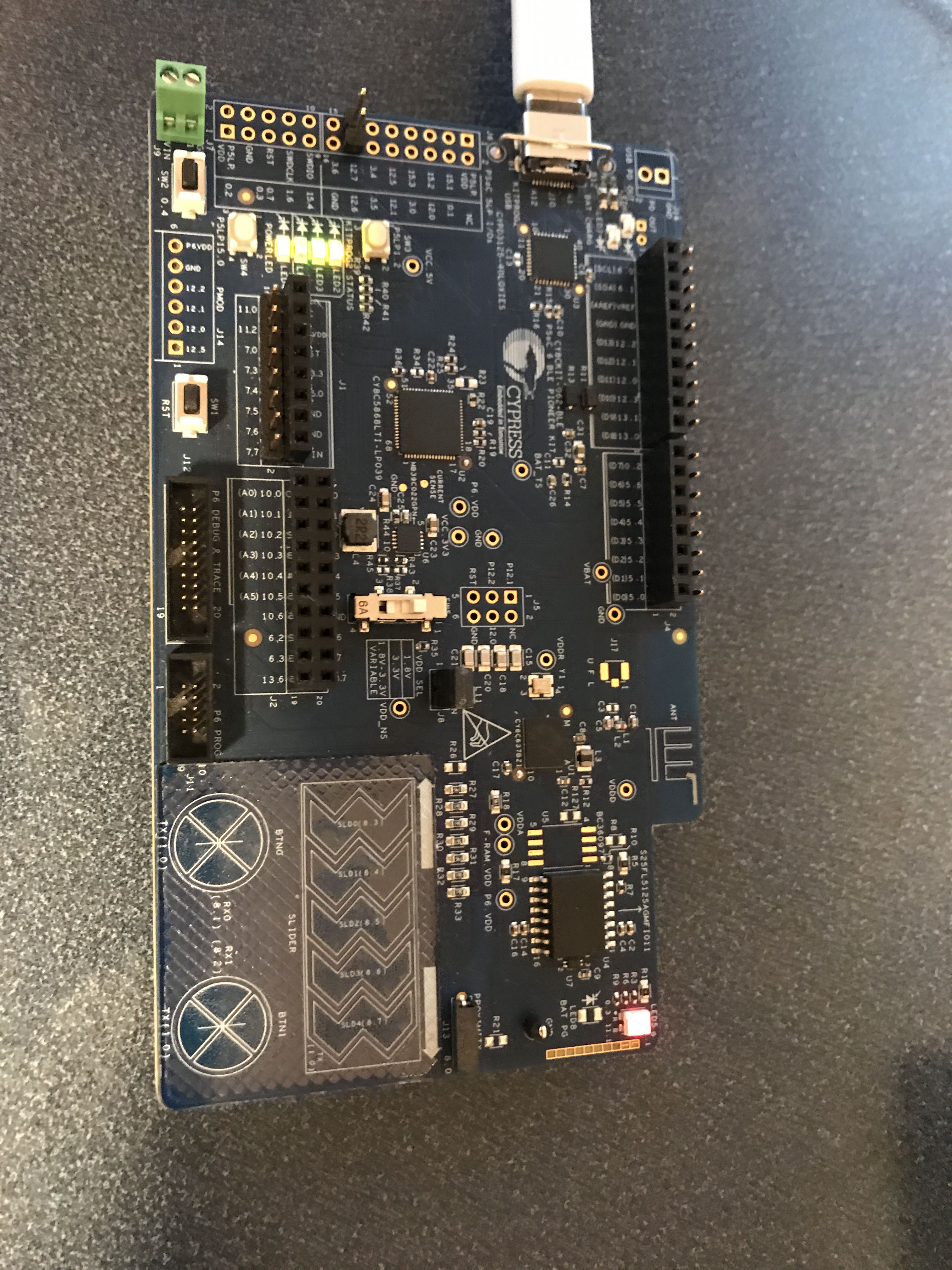
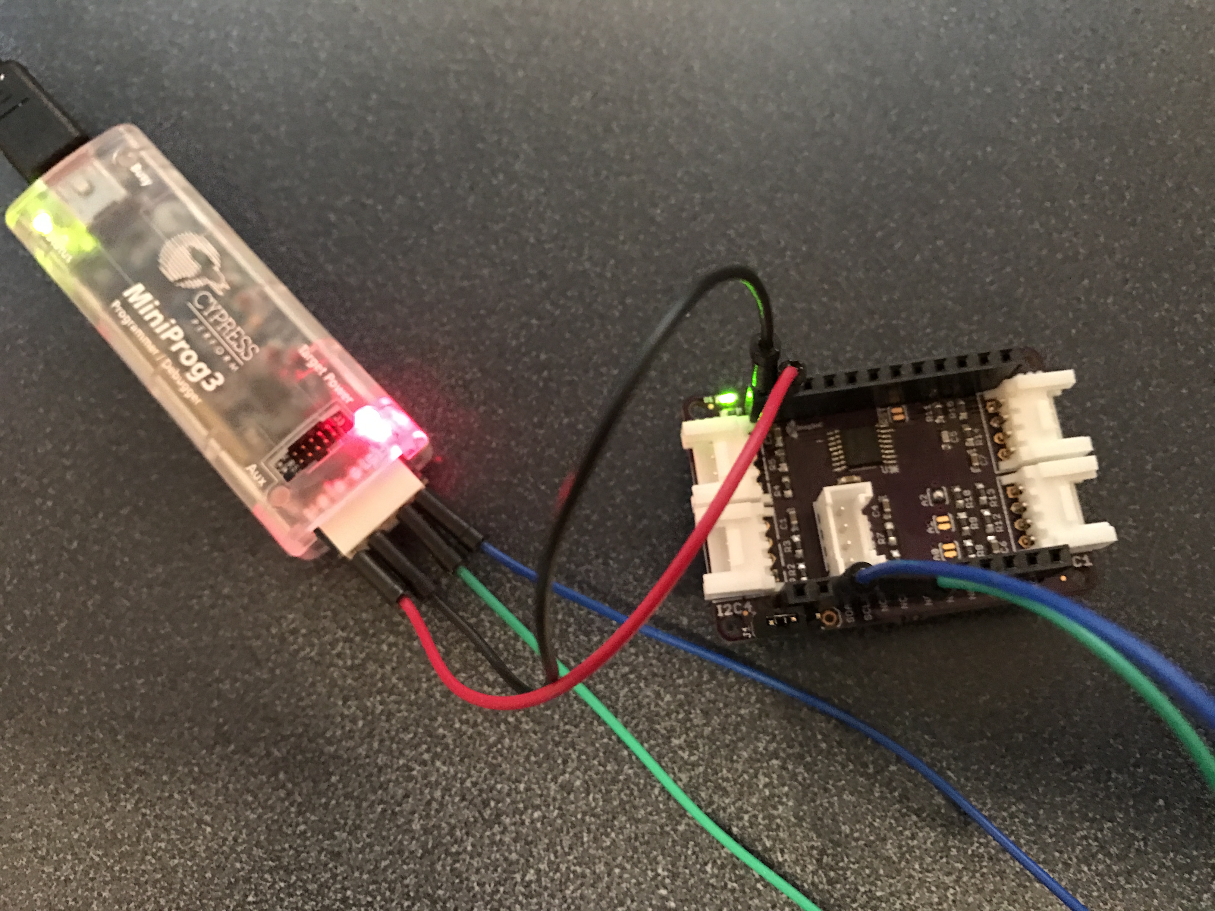
Next… I love the CY8CKIT-059 which you can buy from RS Components. It is a $10 kit with a PSoC 5 and a PSoC KitProg (which is implement in a PSoC 5) which can program and debug. It comes in a flat cardboard mailer.
There are a number of things, that if I was going to spend anymore time on this project (which I am not), that could be improved:
- I could have used the external components to better document the schematic
- I could do the project using the TCPWM on PSoC 4
- I could have use DMA to completely eliminate the ISR
- I could have “kept counting” instead of setting the result to 0 on TC
- I’m sure Greg thinks that I need more comments.
And finally a shout out to Bob Marlow who is a really good PSoC guy and answers tons of questions on our forum. He said something about the c-keyword “volatile” which I thought was wrong… but after digging in some more realized that he was right. That one bit of knowledge made this whole thing worth while.
Lastly… if you see something wrong please post a comment and Ill fix it.


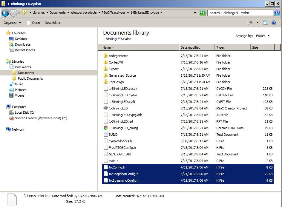


