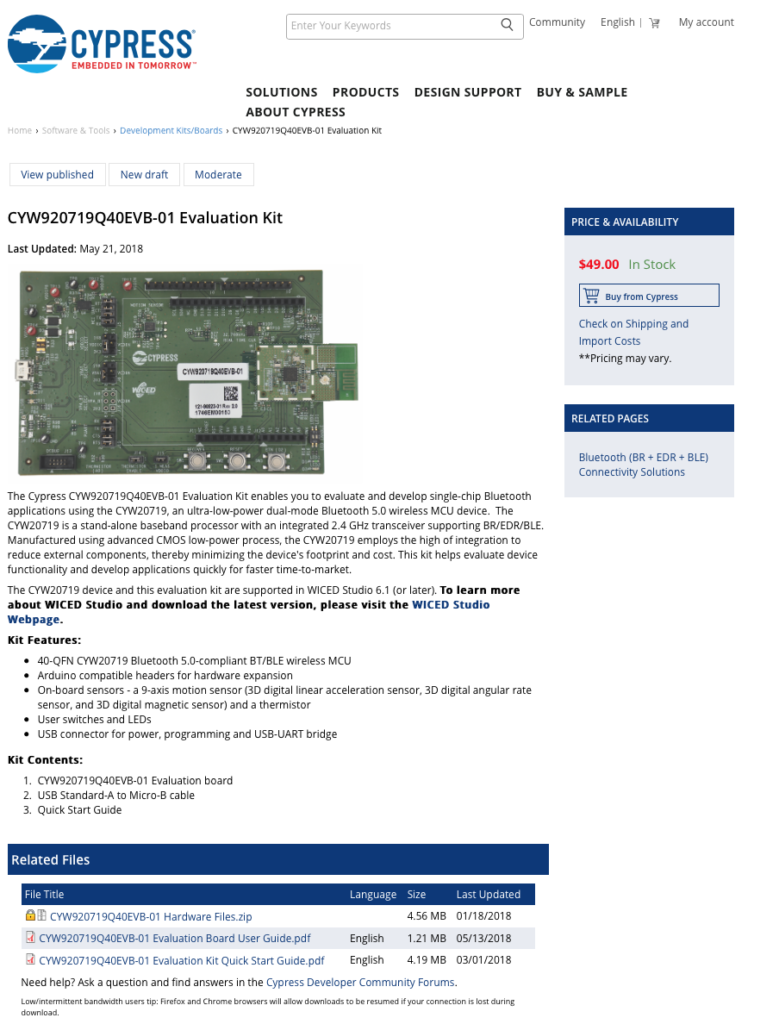
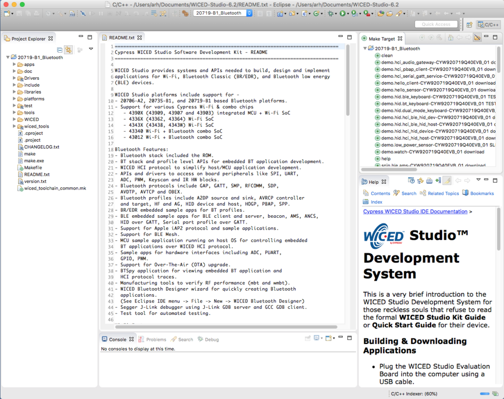
WICED Bluetooth Using the CYW20719
#
Title
Comment
0
A Two Hour WICED Bluetooth Class
WICED Bluetooth Using the CYW20719 in all its glory
1
Resources
Links to all of the Cypress WICED information including videos, application notes etc.
2
Your First Project
Making Hello World & the Blinky LED
3
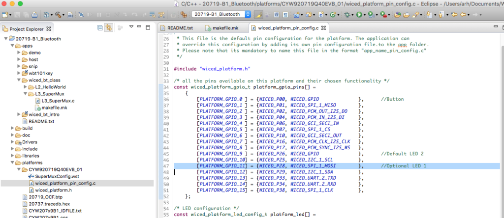
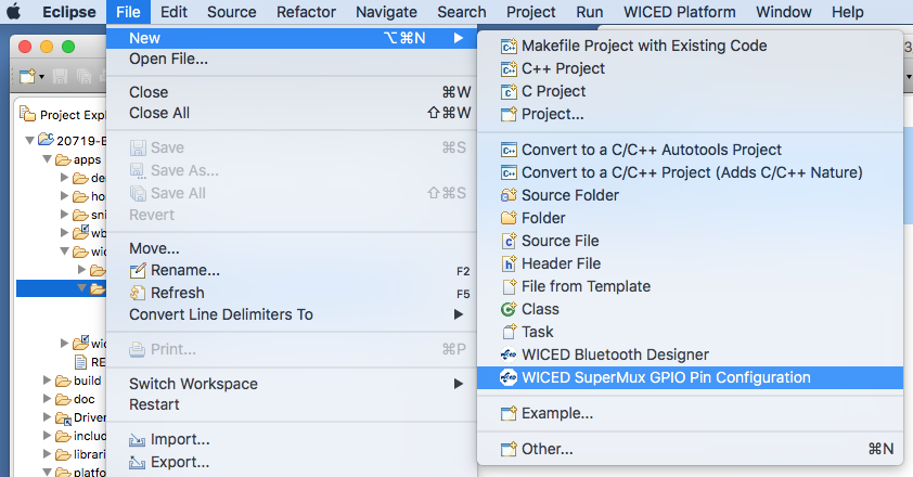
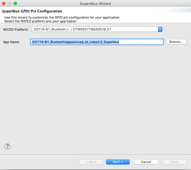
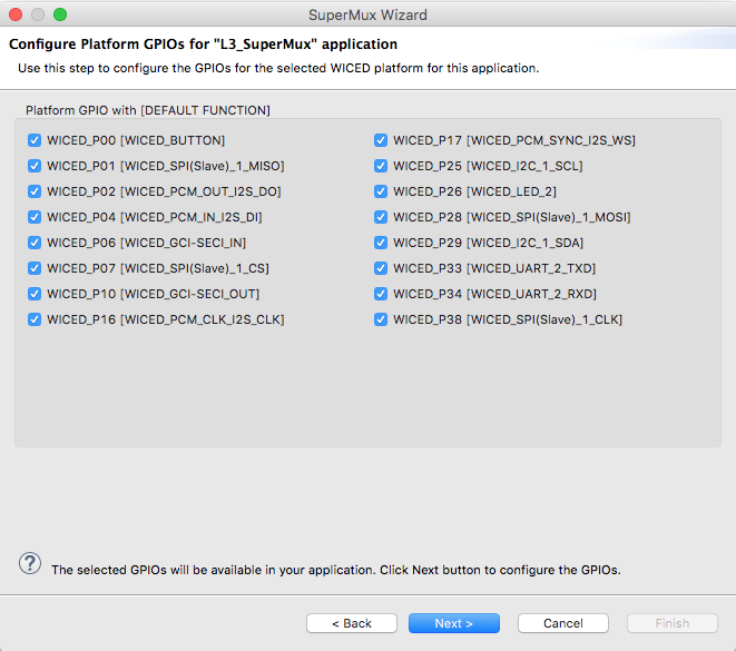
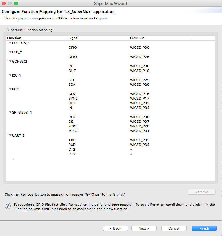
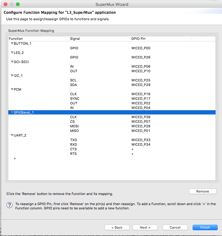
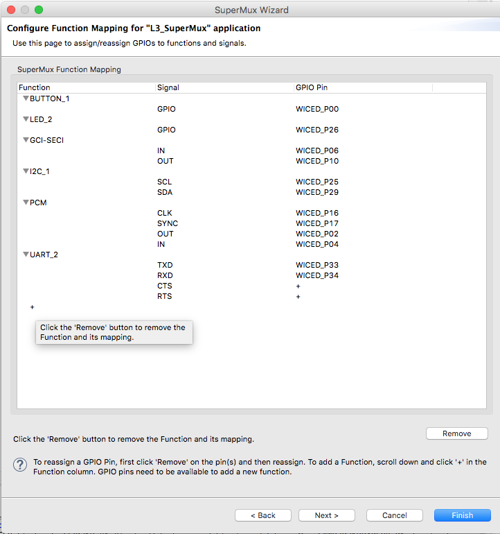
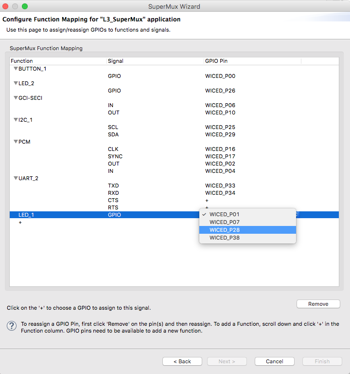
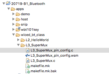
The Super Mux Tool
Learning about platforms and the Super Mux Tool
4
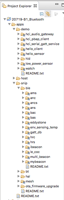
Snips
Using the example projects to learn Bluetooth
5
Bluetooth Designer
Using the tool to customize a project and get going fast
6
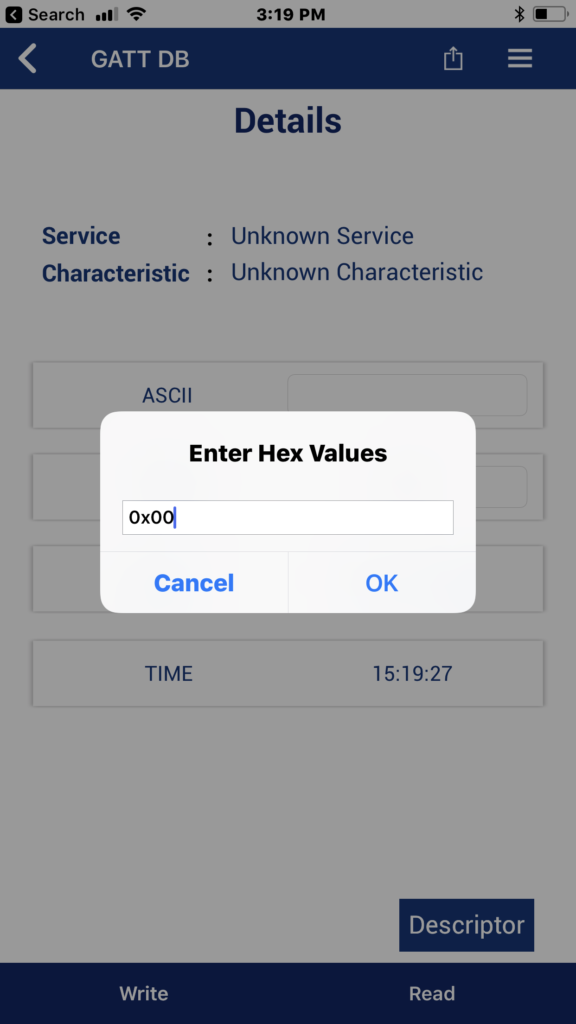
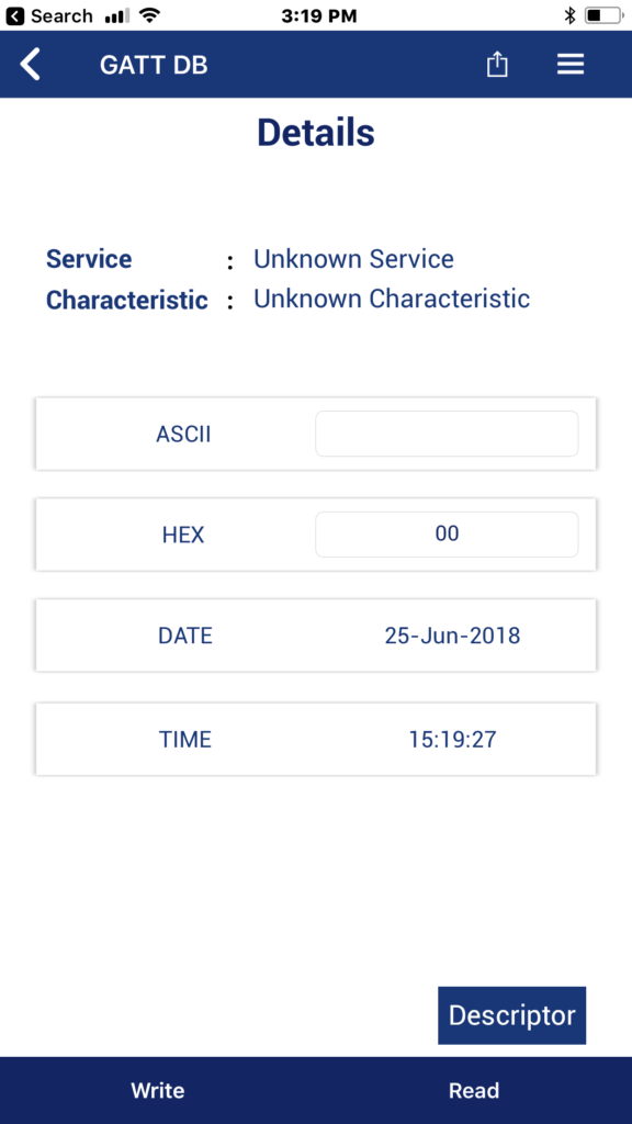
The CCCD & Notification
Writing back to the Central
7
Advertising Beacon
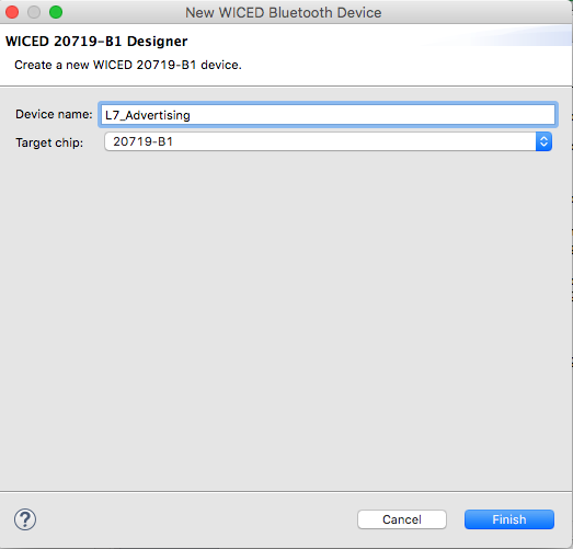
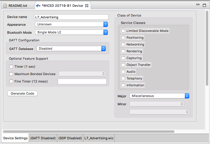
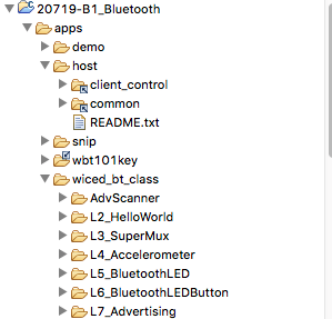
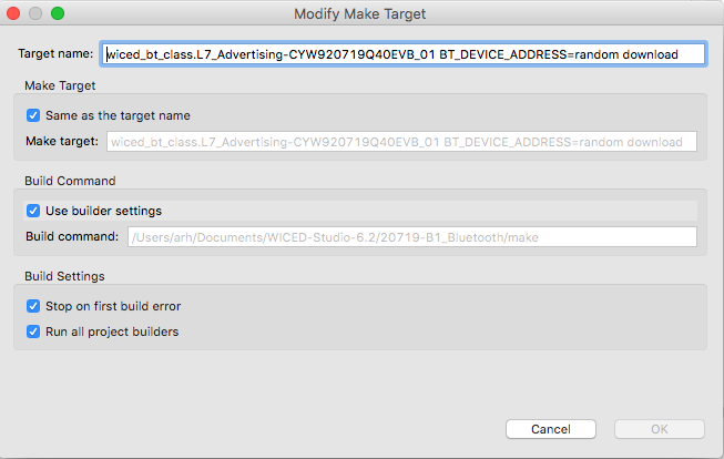
Building a beacon project to advertise your custom information
8
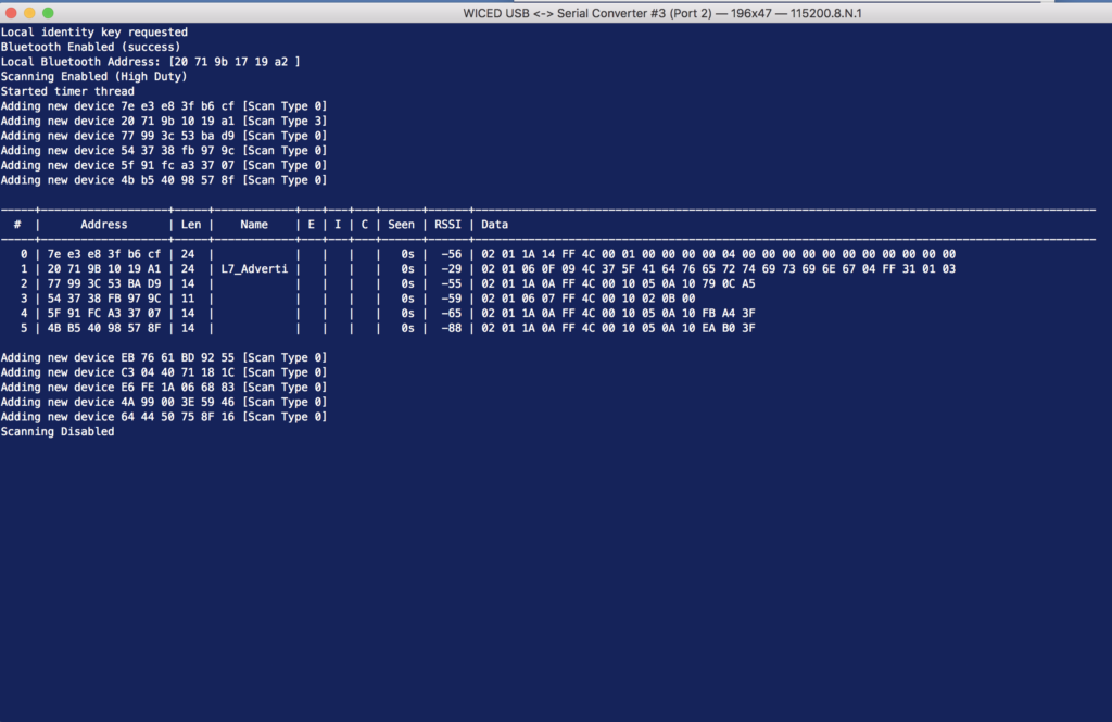
Scanner
Viewing the world around you
9
Bluetooth Classic SPP
Using the Serial Port Profile to Transmit Lots of Data
Source code:
- git@github.com:iotexpert/wiced_bt_intro.git
- https://github.com/iotexpert/wiced_bt_intro
Summary
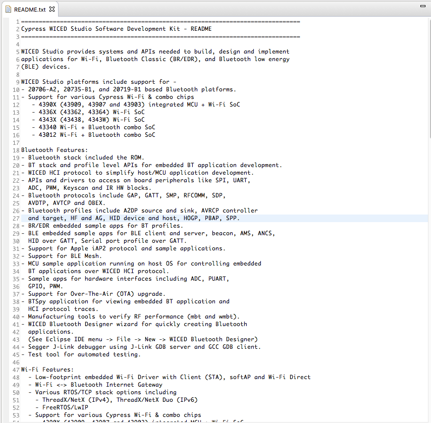
In all of the previous examples I have been using Bluetooth Low Energy. One of the great benefits of the Cypress CYW20719 is that it is a Combo Radio. Combo means that it can use both Bluetooth Low Energy as well as Bluetooth Classic. I am late to the Bluetooth game but as best I can tell Bluetooth Classic and Bluetooth Low Energy are exactly the same … except everything is different. When Bluetooth was originally conceived, one of the principal functions was to act as “serial port wire cutter”. Everywhere you looked there were devices that used a serial port wire, e.g. mice, printers, keyboards etc.
For this lesson we are going to dip back into the snip directory to get a Bluetooth Classic program to start with. The program snip.bt.spp implements the Serial Port Profile (SPP). The SPP is emulates a classic serial port. It has all of the uart wires that we know and love including rx,tx,cts etc. What this allows you to do is open up a high speed (much faster than BLE) connection.
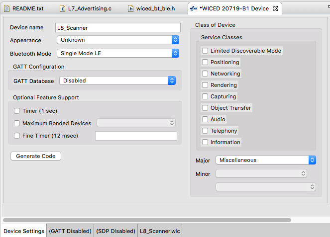
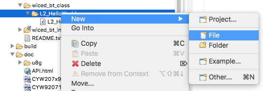
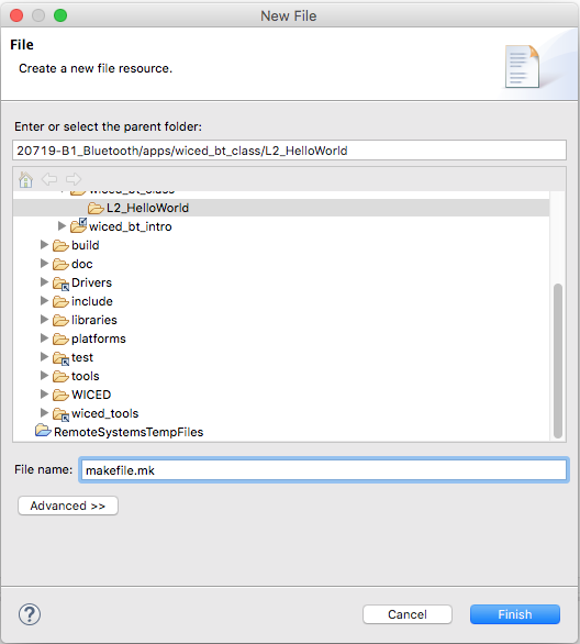
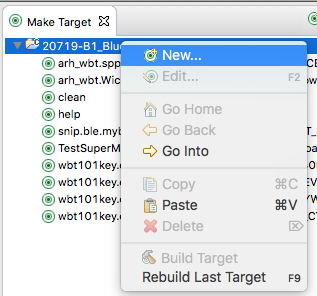
To implement this lesson I will perform the following steps
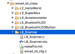
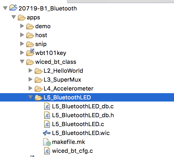
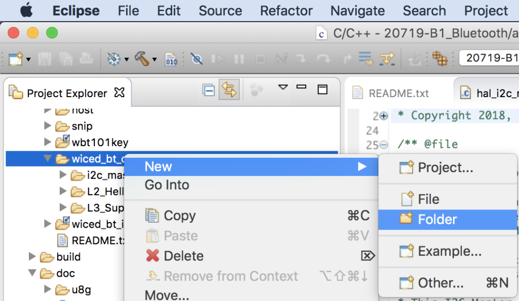
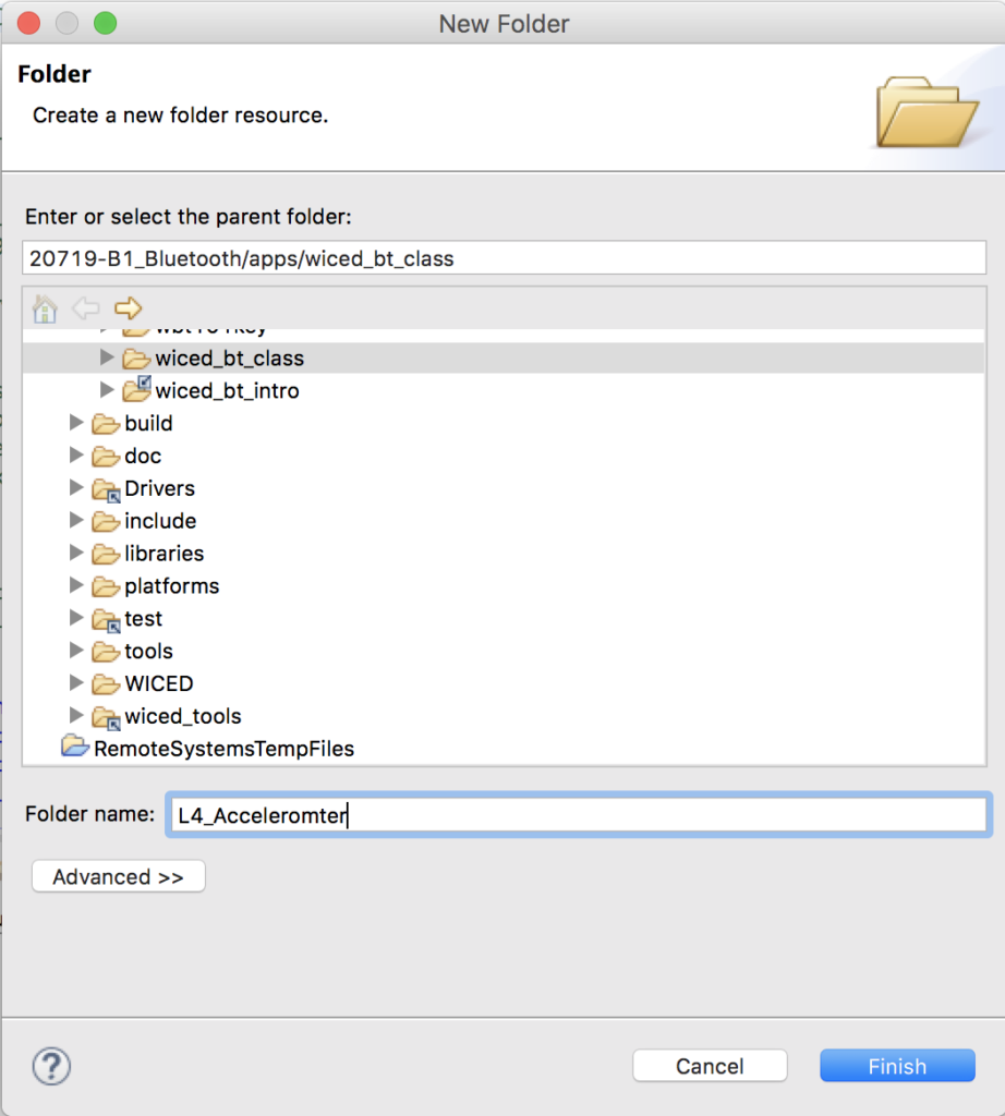
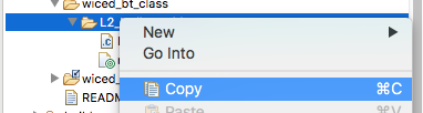
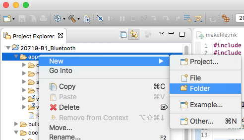
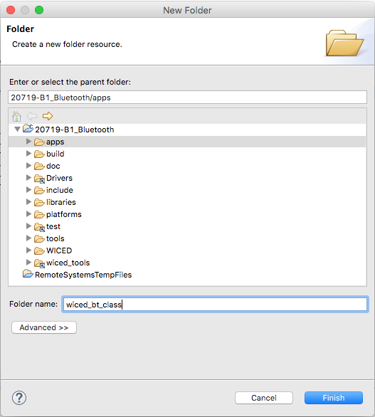
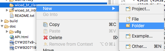
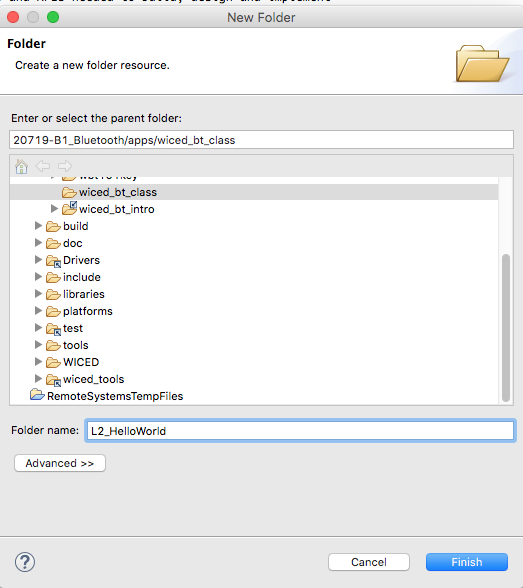
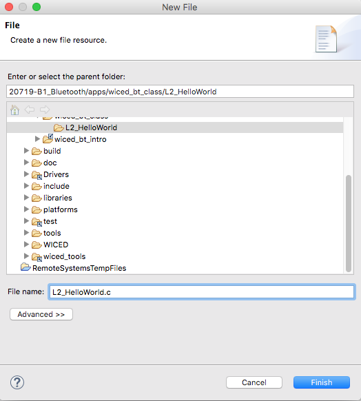
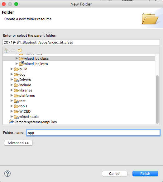
- Make a new folder in the wiced_bt_class folder
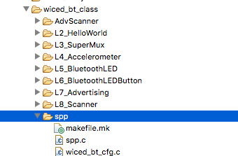
- Copy the files from apps/snip/bt/spp into my new folder
- Create a make target and program it
- Make a connection using a Bluetooth serial port on my Mac
- Look at where the pin is set
- Examine the spp setup code
- Modify it to print out all the data sent to the SPP
Implement the SPP

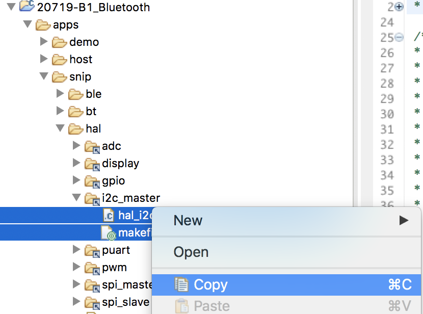
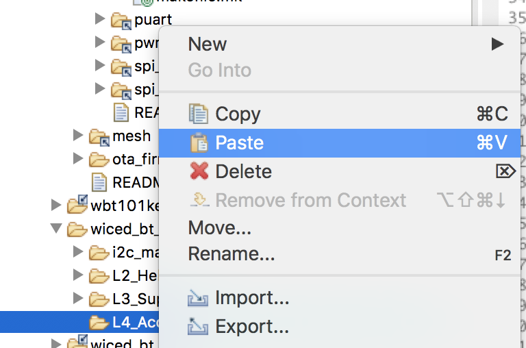
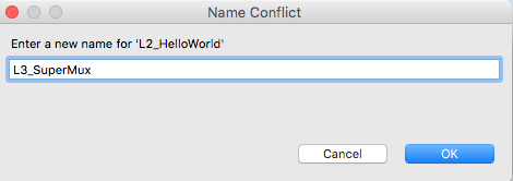
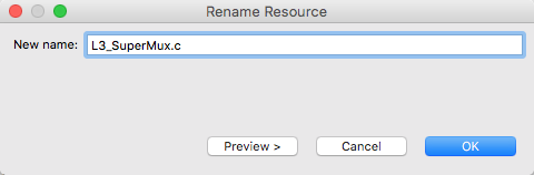
Set the folder name to “spp”
Copy and past the files from the folder apps.snip.bt.spp
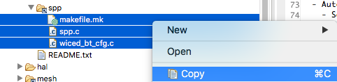
And paste them into your new spp folder
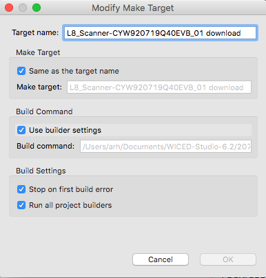
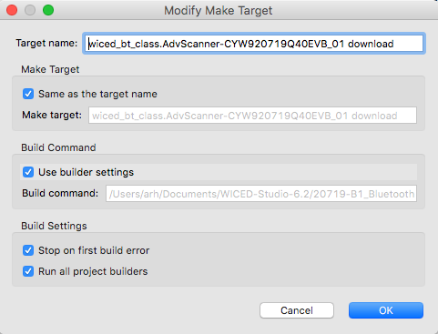
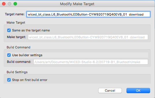
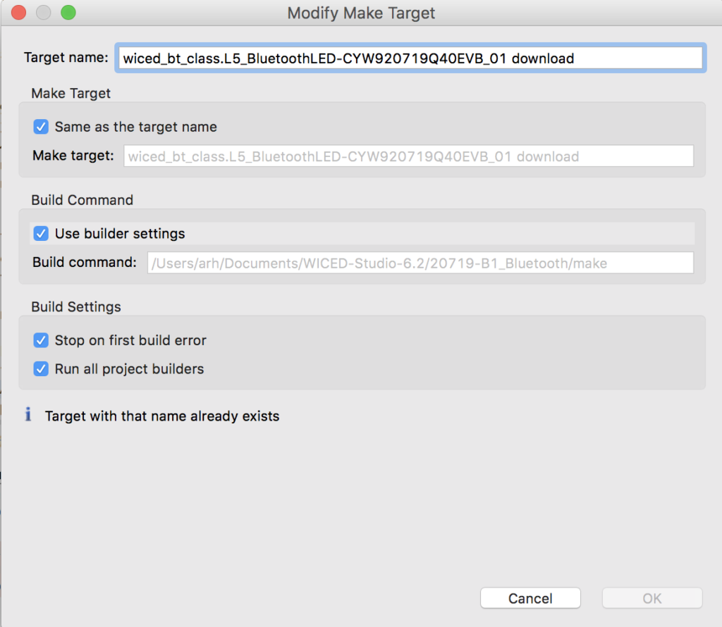
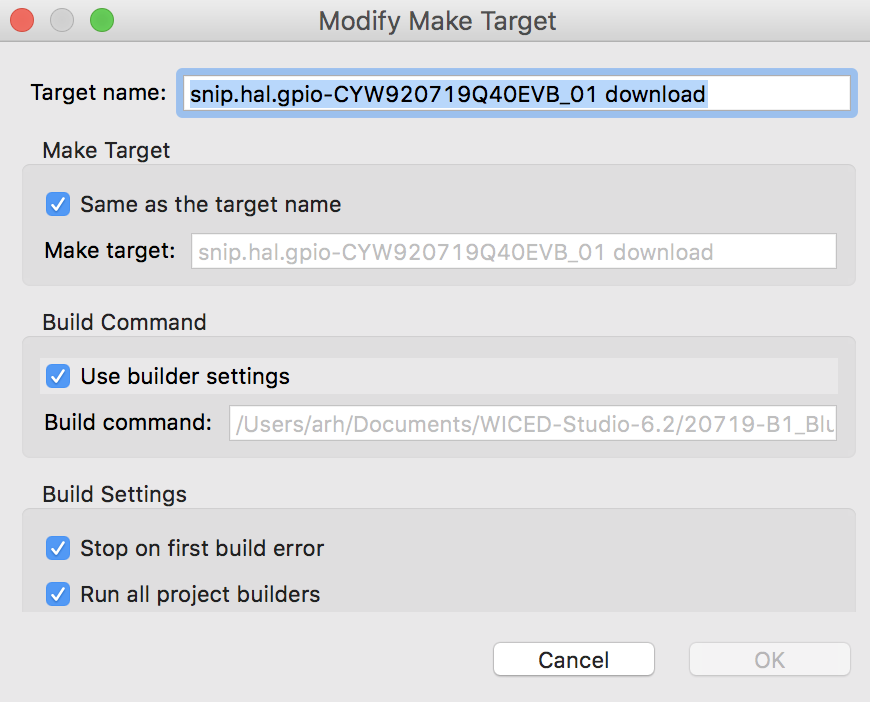
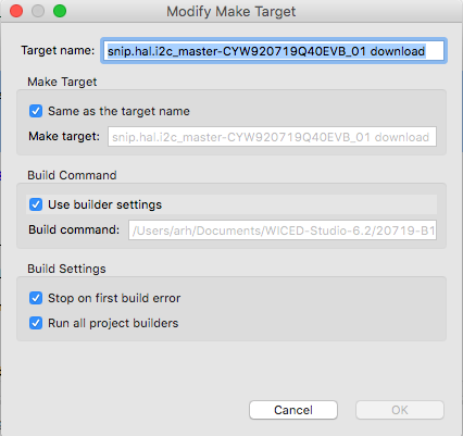
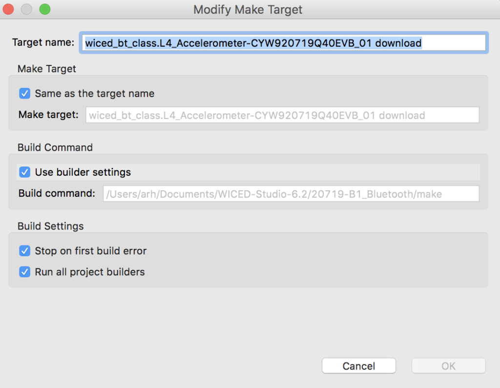
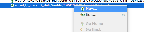
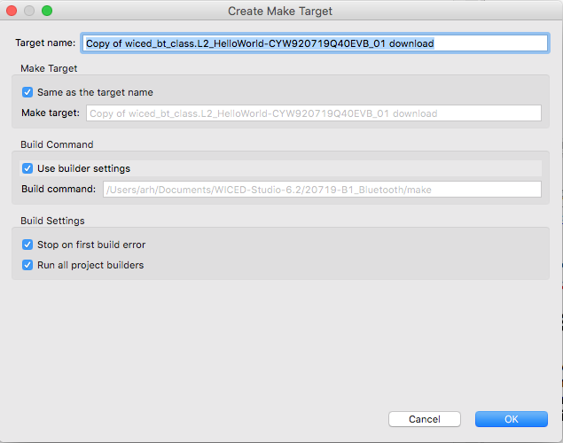
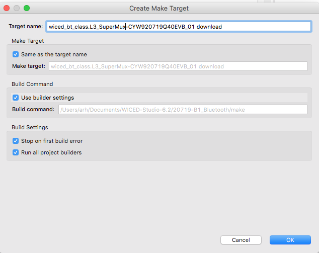
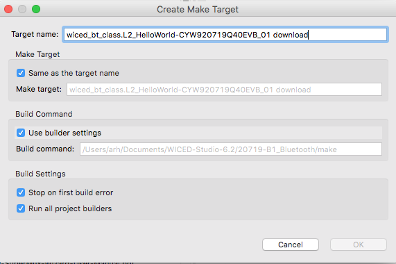
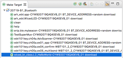
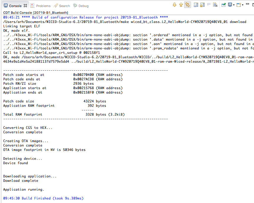
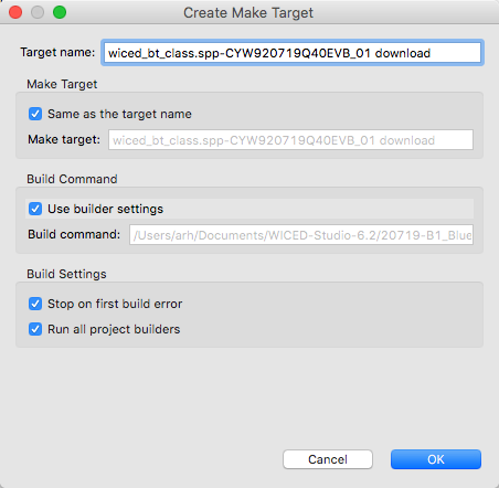
Create a make target for your spp project
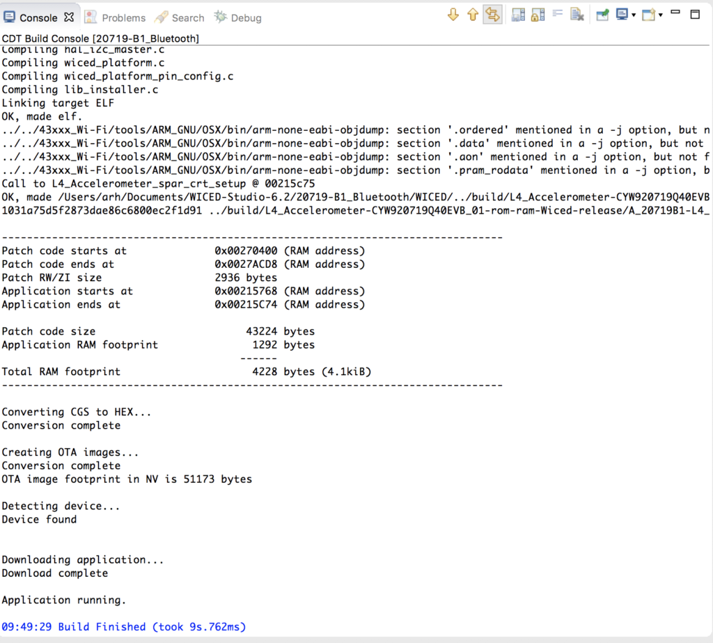
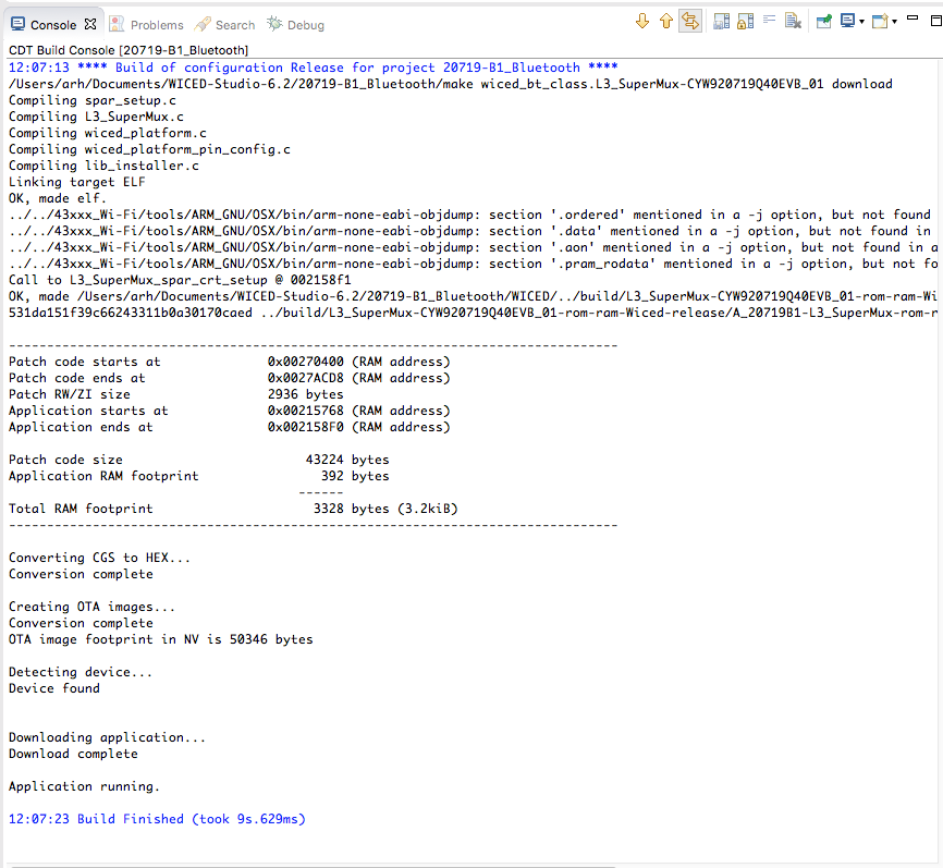
Program the board with your project
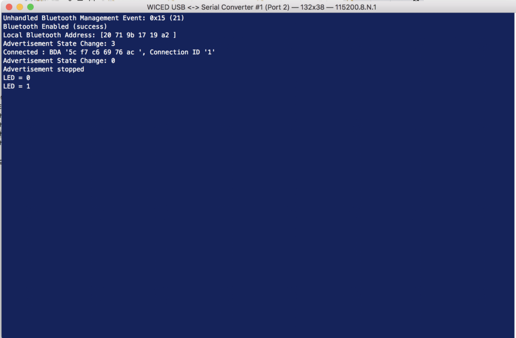
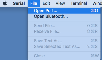
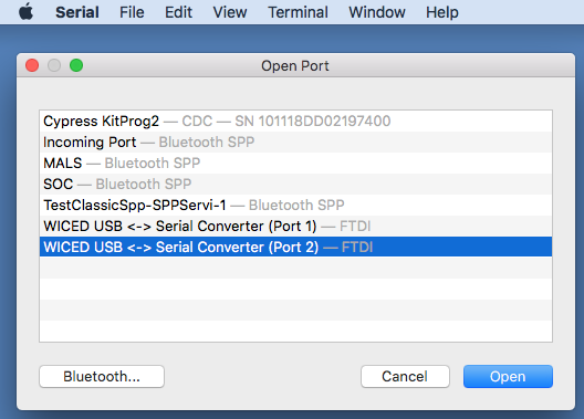
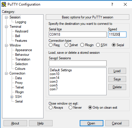
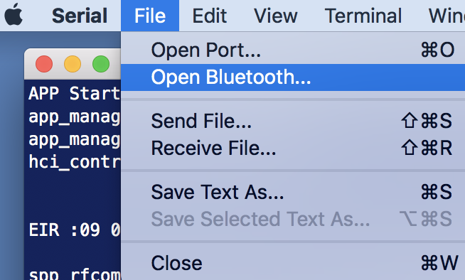
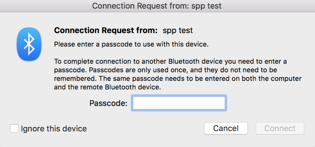
Now tell the computer to open a classic connection by running file->open bluetooth
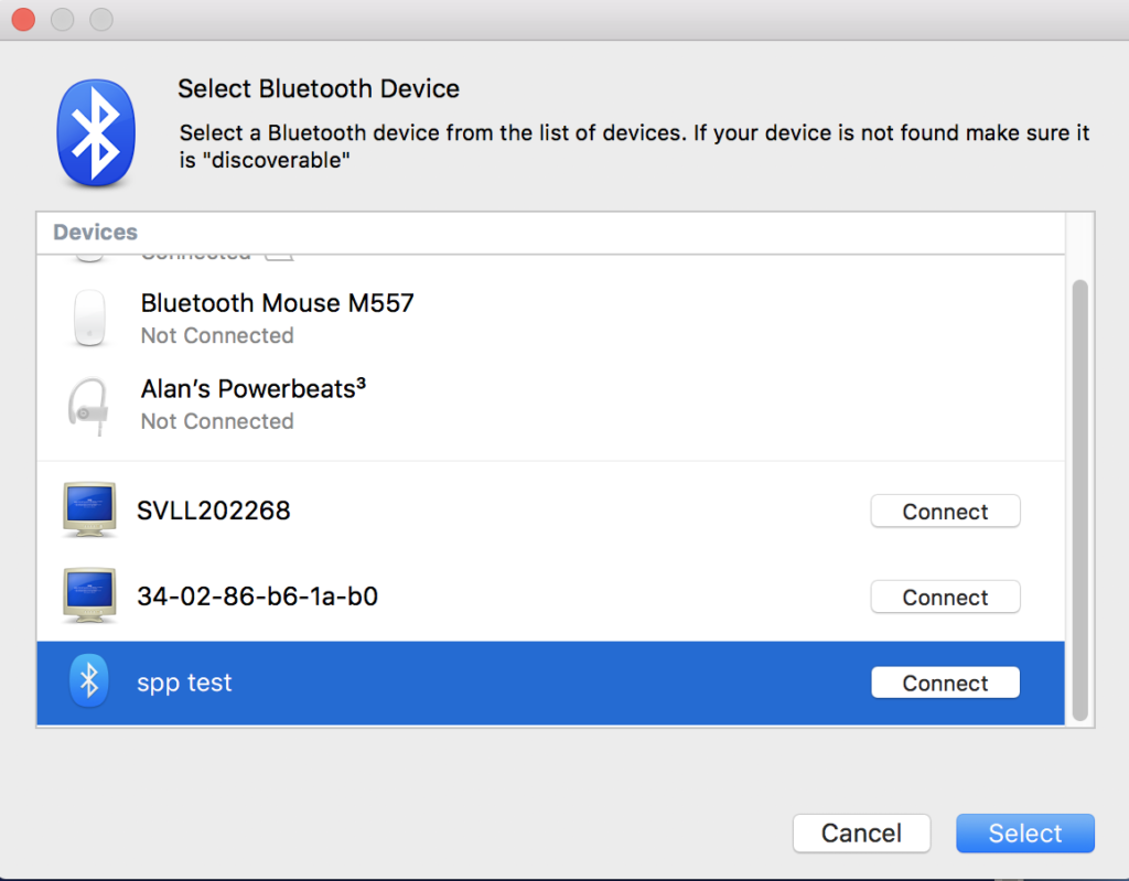
Select the “spp test”
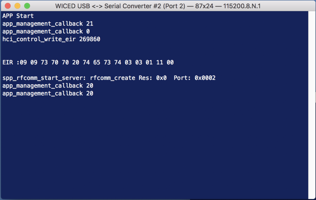
Now press some keys on the new terminal window… and look at the output window of the “spp test”
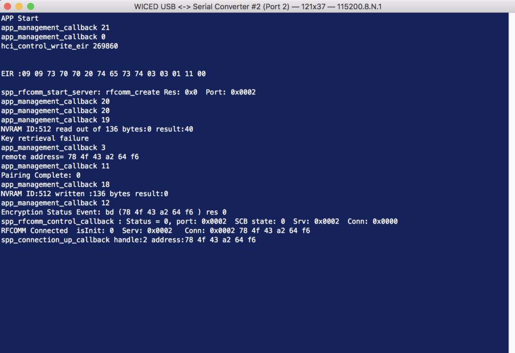
Type in the pin code which is 0000.
But, how did I know the pin code? Look at the source code.
uint8_t pincode[4] = { 0x30, 0x30, 0x30, 0x30 };
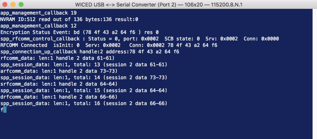
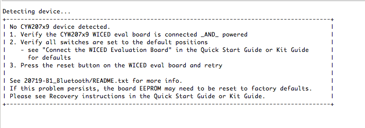
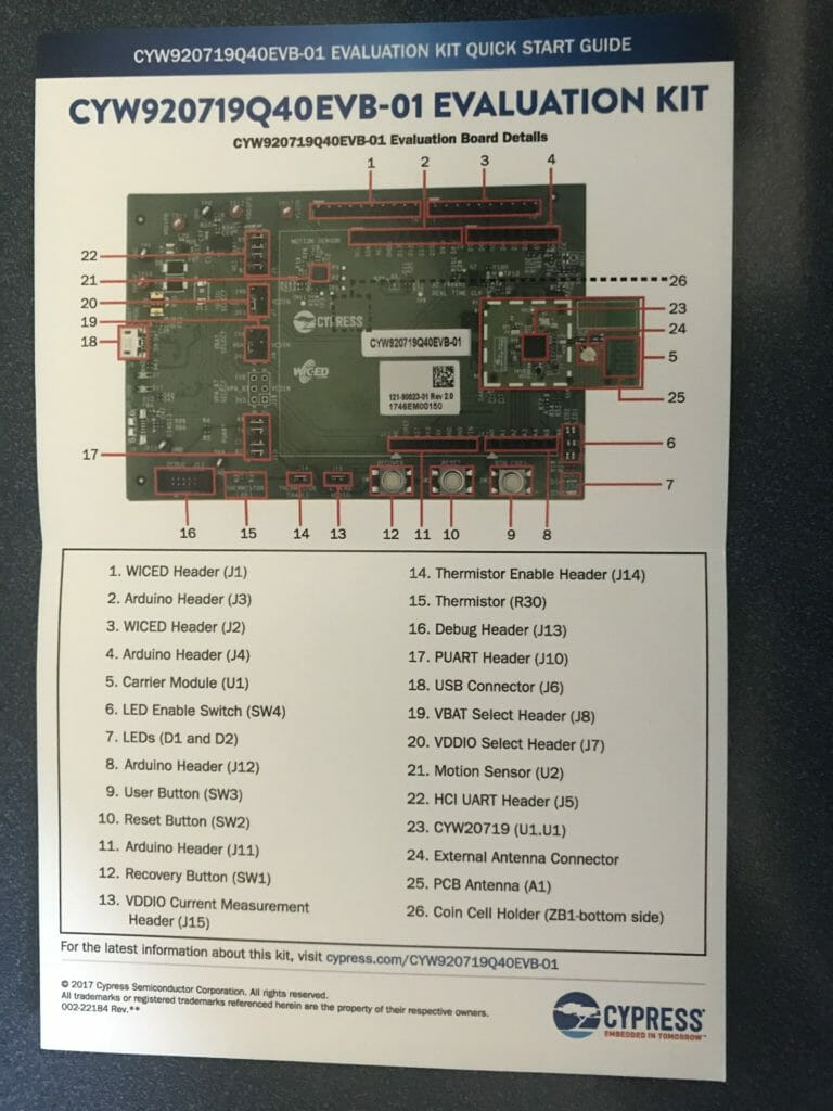
Now, when you press keys on the “Bluetooth serial terminal” you will see a not very helpful message on the CYW920719Q40EVB-01 terminal window.
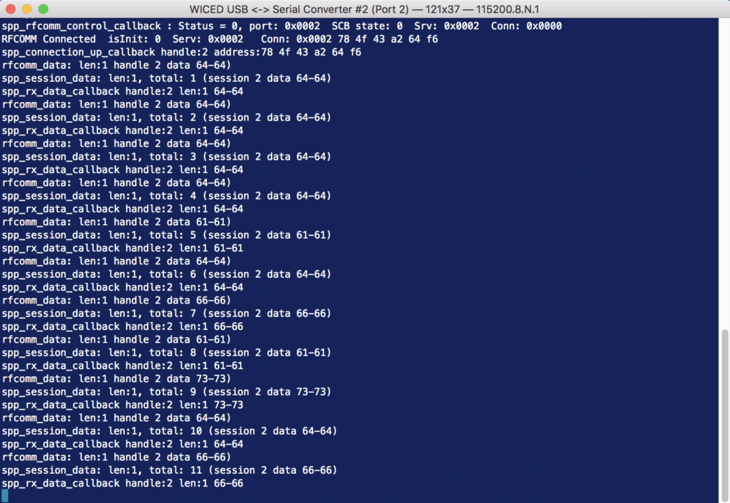
I think that it would be better to print out the characters that the person types. So lets figure out how this works. In the application init function on line 251 there is a call to wiced_bt_spp_startup
void application_init(void)
{
    wiced_bt_gatt_status_t gatt_status;
    wiced_result_t         result;


#if SEND_DATA_ON_INTERRUPT
    /* Configure the button available on the platform */
    wiced_platform_register_button_callback( WICED_PLATFORM_BUTTON_1, app_interrupt_handler, NULL, WICED_PLATFORM_BUTTON_RISING_EDGE);

    // init timer that we will use for the rx data flow control.
    wiced_init_timer(&app_tx_timer, app_tx_ack_timeout, 0, WICED_MILLI_SECONDS_TIMER);
#endif

    app_write_eir();


    // Initialize SPP library
    wiced_bt_spp_startup(&spp_reg);
That function takes a pointer to a structure with a bunch of interesting things in it. Notice that there is a function called “spp_rx_data_callback” that is called every time that data come in from the SPP.
wiced_bt_spp_reg_t spp_reg =
{
    SPP_RFCOMM_SCN,                     /* RFCOMM service channel number for SPP connection */
    MAX_TX_BUFFER,                      /* RFCOMM MTU for SPP connection */
    spp_connection_up_callback,         /* SPP connection established */
    NULL,                               /* SPP connection establishment failed, not used because this app never initiates connection */
    NULL,                               /* SPP service not found, not used because this app never initiates connection */
    spp_connection_down_callback,       /* SPP connection disconnected */
    spp_rx_data_callback,               /* Data packet received */
};
Now look at the function spp_rx_data_callback. All it does is print out a message saying how much data and the hex value of the data.
wiced_bool_t spp_rx_data_callback(uint16_t handle, uint8_t* p_data, uint32_t data_len)
{
    int i;
//    wiced_bt_buffer_statistics_t buffer_stats[4];

//    wiced_bt_get_buffer_usage (buffer_stats, sizeof(buffer_stats));

//    WICED_BT_TRACE("0:%d/%d 1:%d/%d 2:%d/%d 3:%d/%d\n", buffer_stats[0].current_allocated_count, buffer_stats[0].max_allocated_count,
//                   buffer_stats[1].current_allocated_count, buffer_stats[1].max_allocated_count,
//                   buffer_stats[2].current_allocated_count, buffer_stats[2].max_allocated_count,
//                   buffer_stats[3].current_allocated_count, buffer_stats[3].max_allocated_count);

//    wiced_result_t wiced_bt_get_buffer_usage (&buffer_stats, sizeof(buffer_stats));

    WICED_BT_TRACE("%s handle:%d len:%d %02x-%02x\n", __FUNCTION__, handle, data_len, p_data[0], p_data[data_len - 1]);

#if LOOPBACK_DATA
    wiced_bt_spp_send_session_data(handle, p_data, data_len);
#endif
    return WICED_TRUE;
}
So, How about instead of that message we just print out the data.
    //WICED_BT_TRACE("%s handle:%d len:%d %02x-%02x\n", __FUNCTION__, handle, data_len, p_data[0], p_data[data_len - 1]);

    for(int i=0;i<data_len;i++)
        WICED_BT_TRACE("%c",p_data[i]);
Now when I run the project and type I see the characters that I type coming out on the serial port.