Summary
The last few weeks of my technical life have been frustrating. Nothing and I mean nothing has been easy. A few weeks ago I replied to a comment about cascading the watch dog timers in the PSoC 4200M to extend the sleep time – the article was called “PSoC 4200M WDT Long Deep Sleep“. I wanted to measure power to see what exactly was happening. But the great technical gods were conspiring against me and I had tons of problems. Well I have things sorted out. In this article I will build a project using the PSoC 4200M Watch Dog Timers and show the power measurements on the CY8CKIT-043 and CY8CKIT-044. I will include PSoC 4200M low power measurements at 5V and 3.3V as well as with both the ILO and the WCO as the source of the WDT. To do this I:
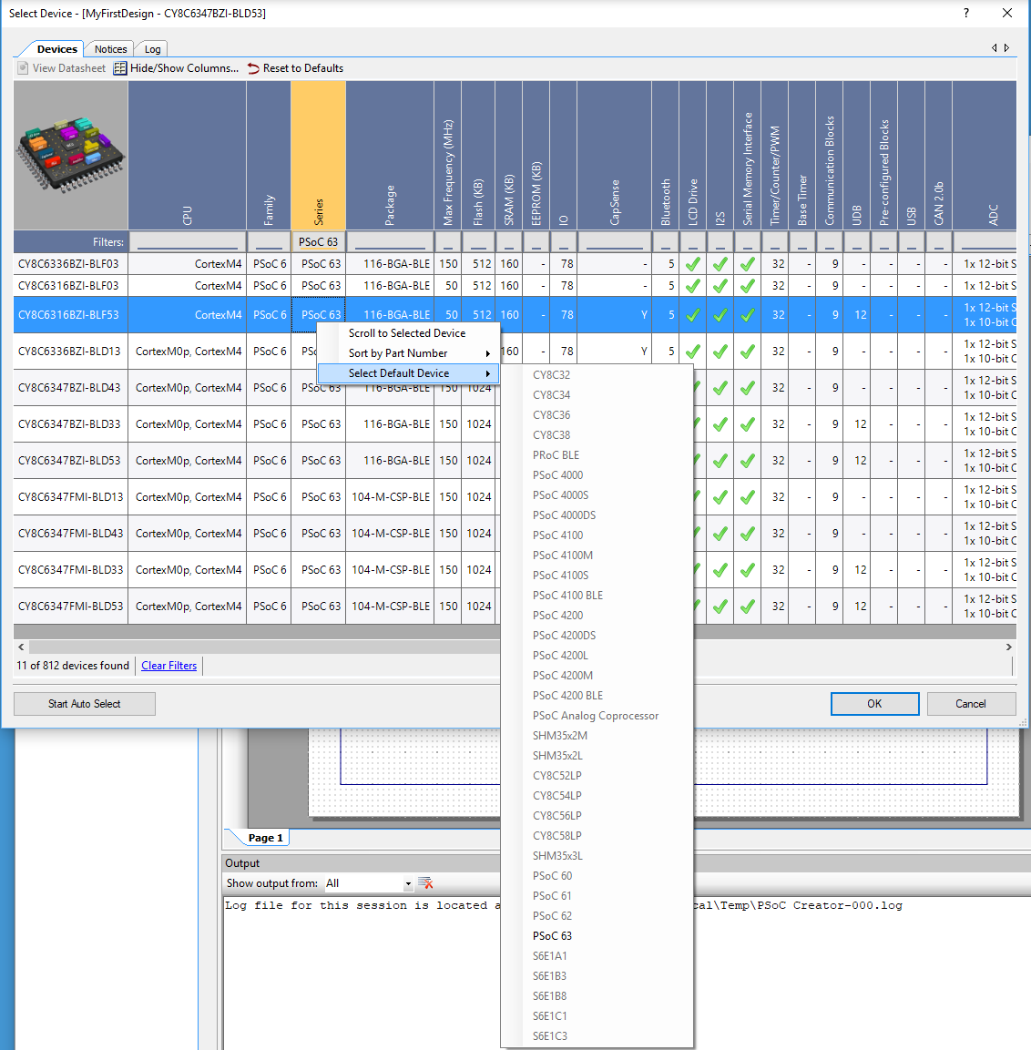
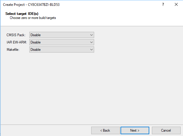
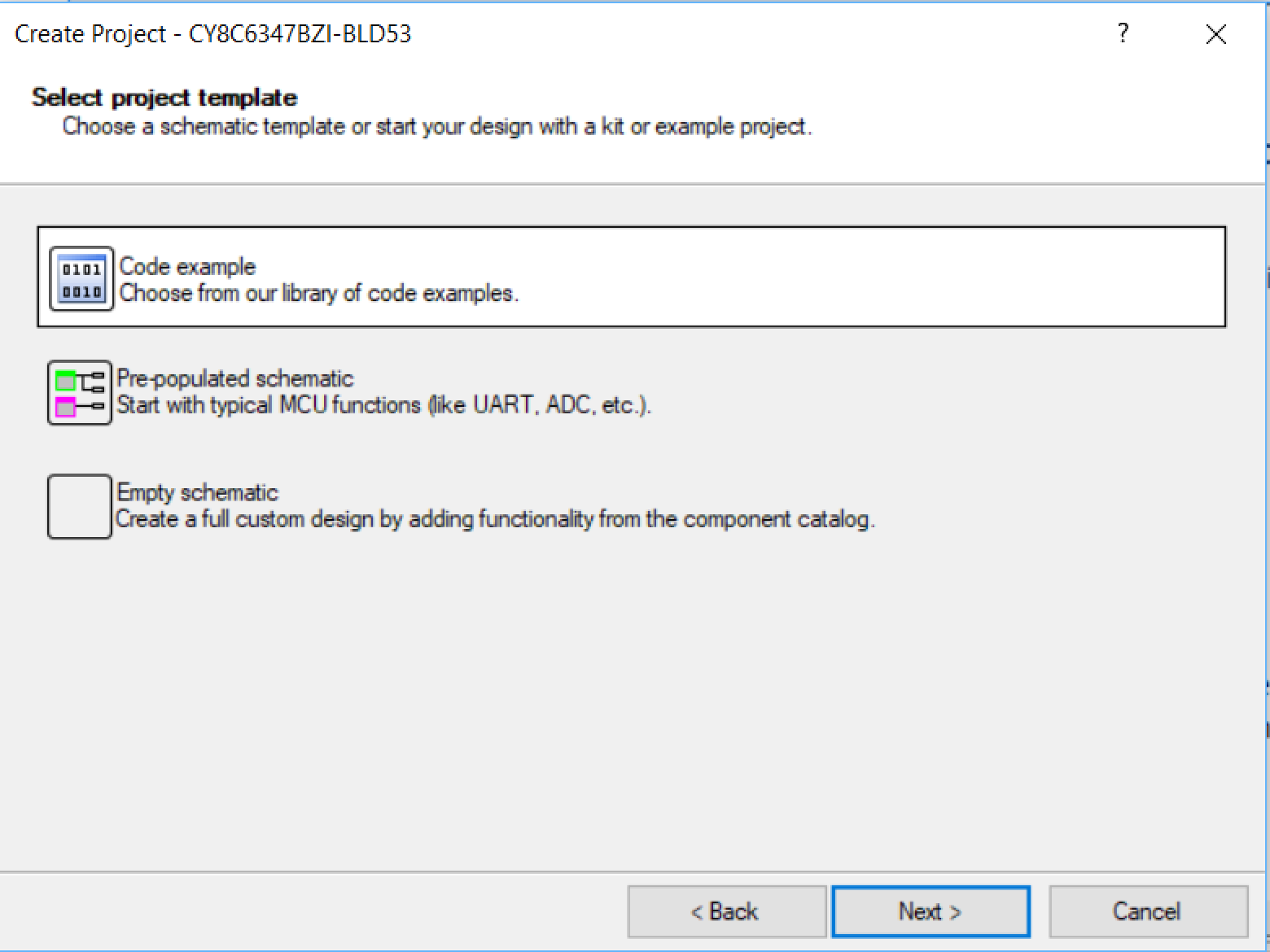
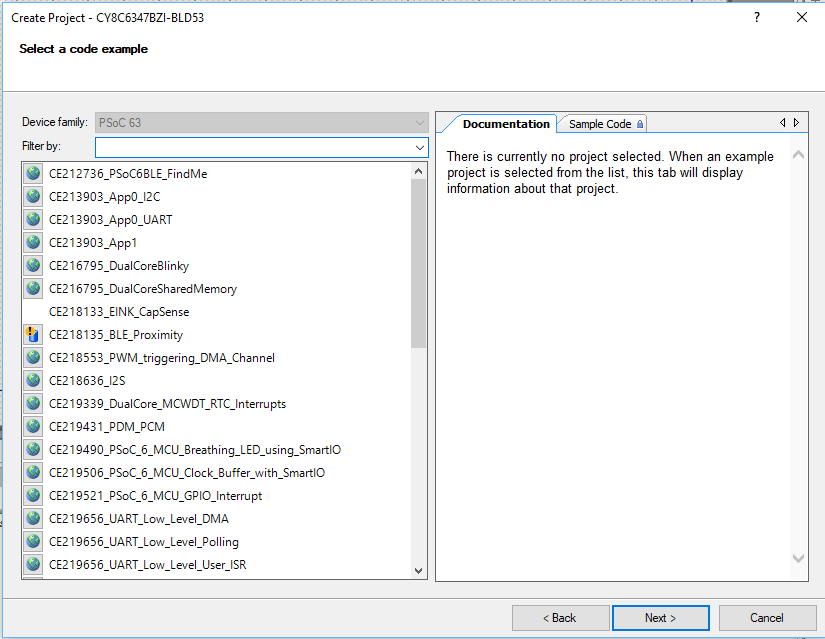
- Created a PSoC 4200M low power project
- Modified the CY8CKIT-043M
- Reject the Fluke 175
- Read the Keysite 34465A Multimeter Manual
- PSoC 4200M Low Power Current Measurement
PSoC 4 Low Power Firmware
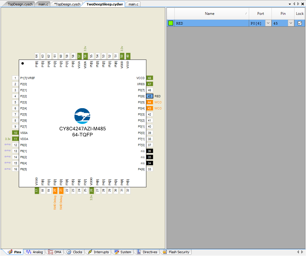
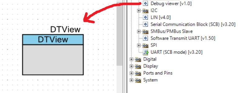
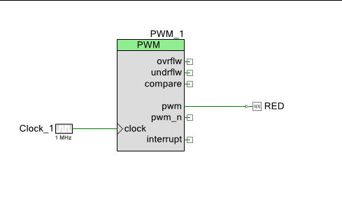
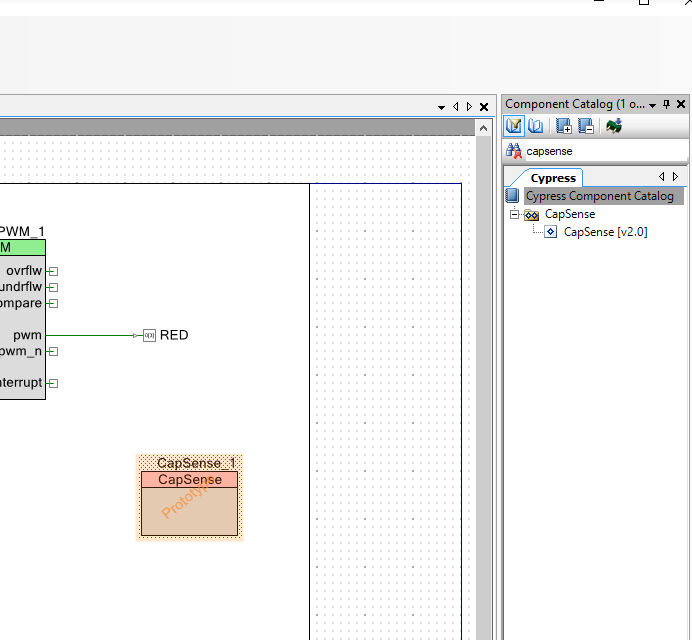
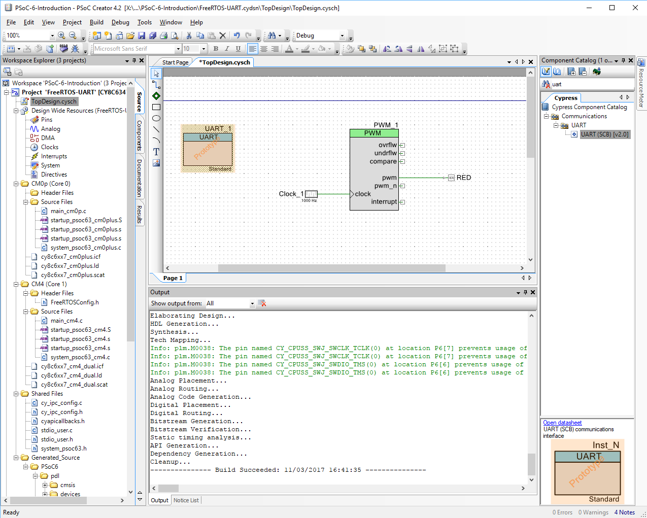
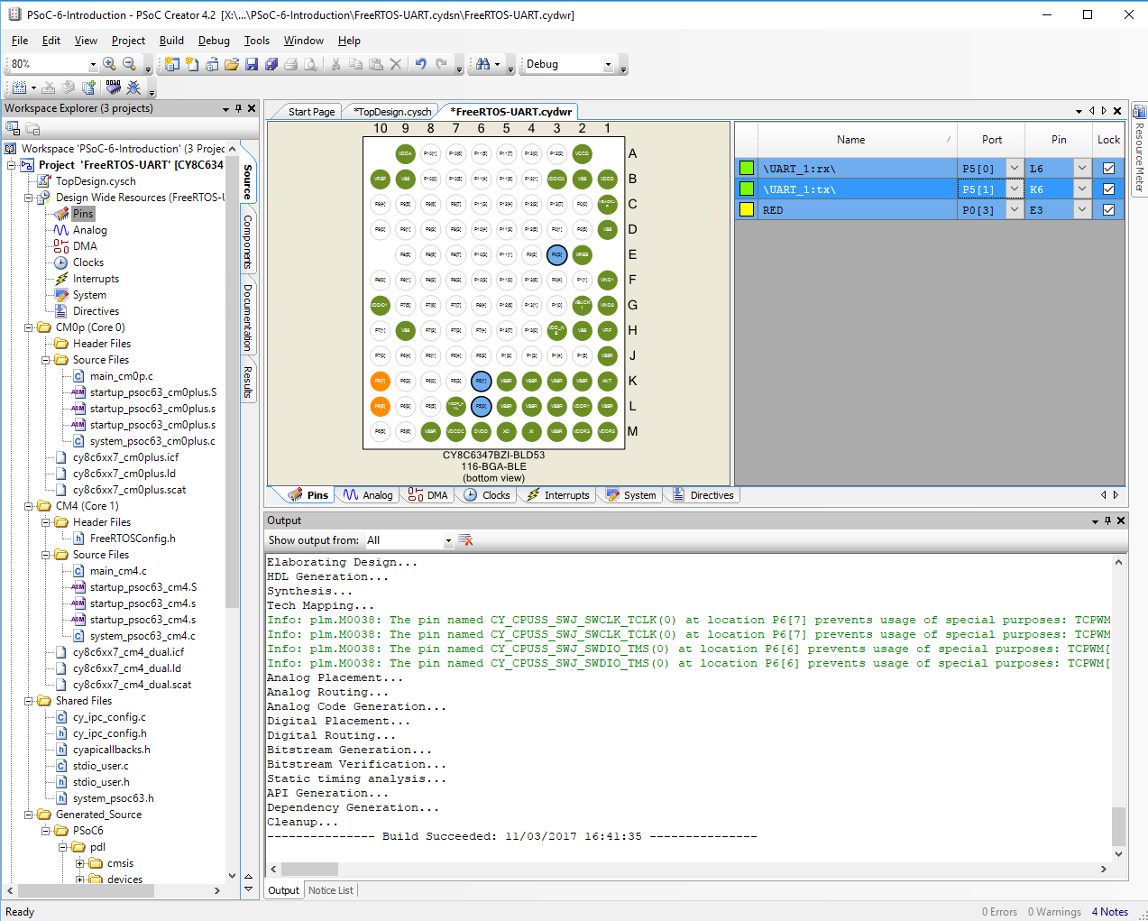
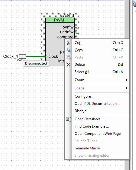
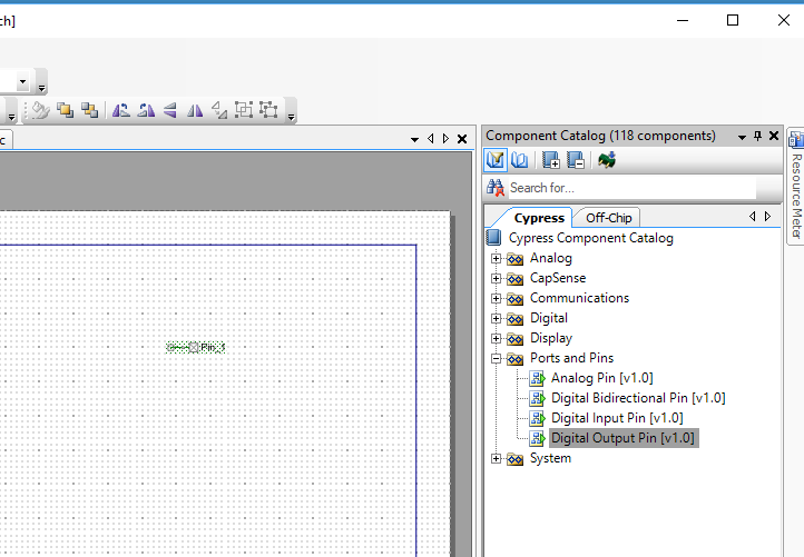
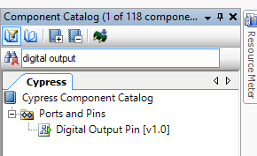
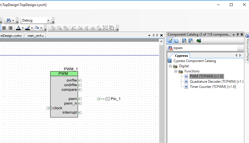
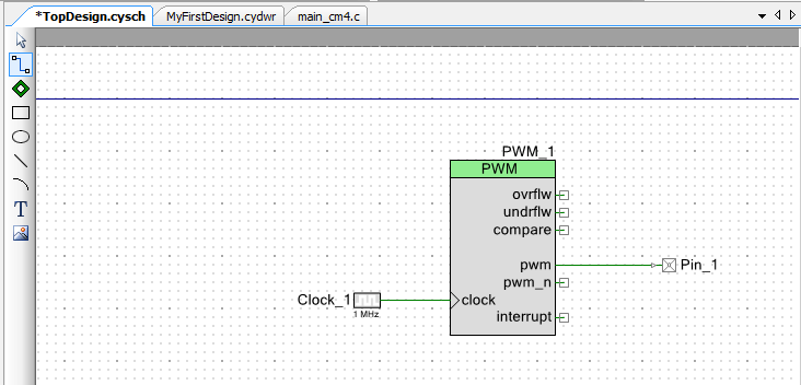
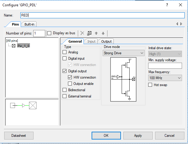
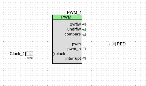
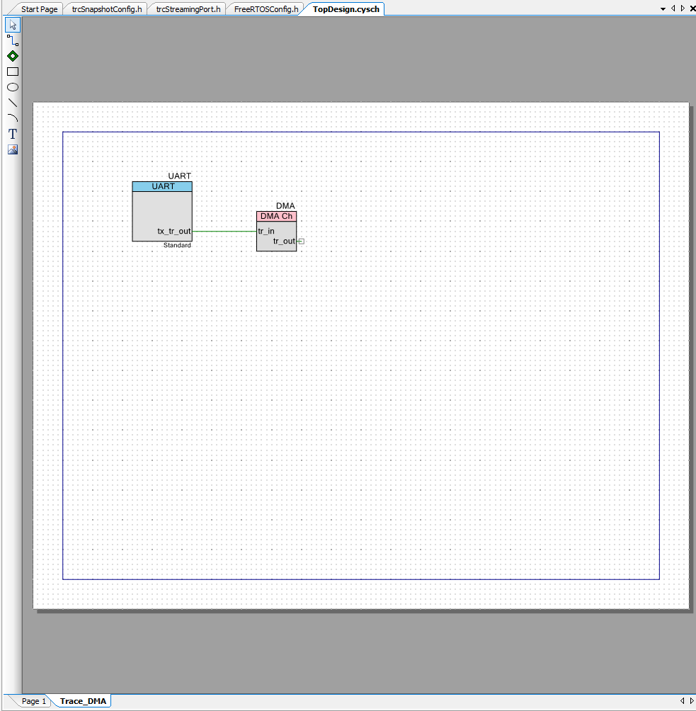
First I create a schematic. This includes 4 digital output pins. The GREEN, RED and BLUE are attached to the tri-color LED. A UART to print the status of the startup. And an interrupt connected to the WDT Interrupt.
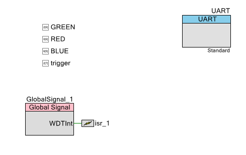
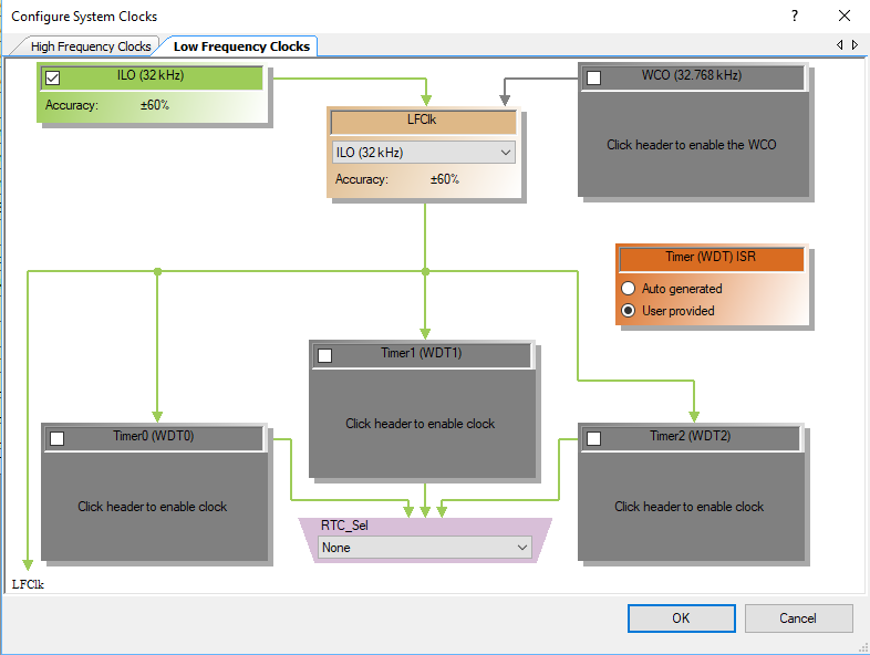
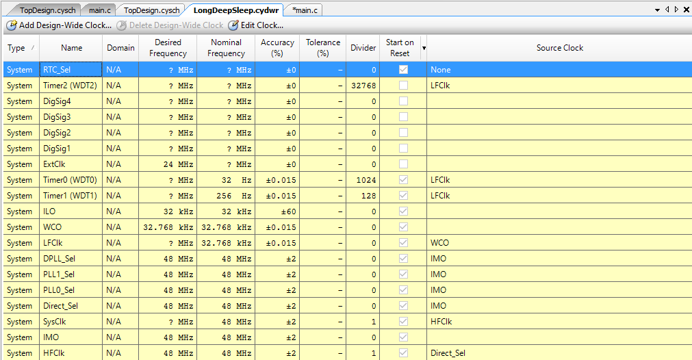
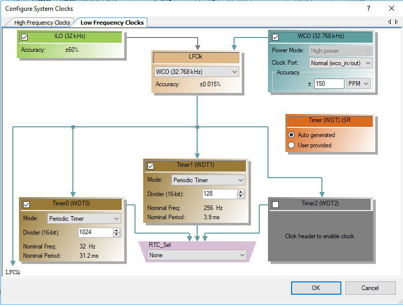
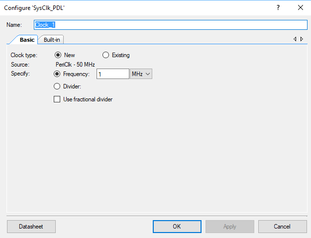
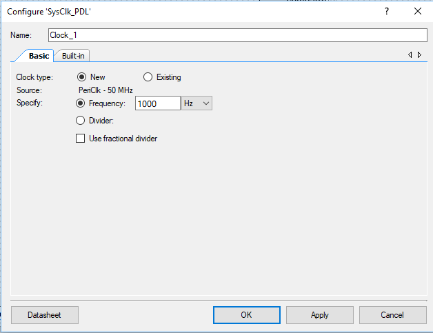
The next thing to do is to make sure that the WDT is being driven by the ILO. I also turn off the three WDTs because I will configure them in the firmware.
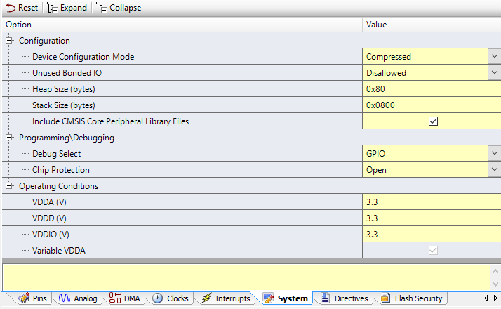
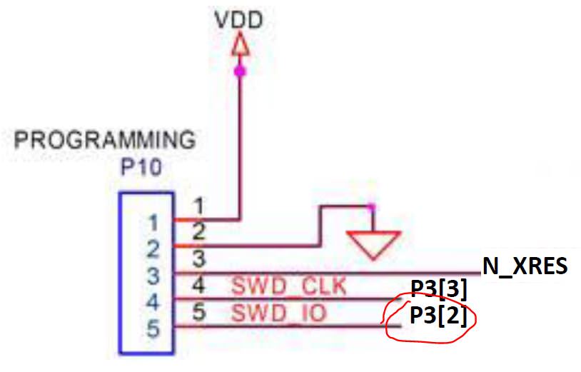
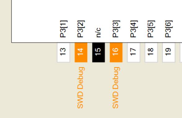
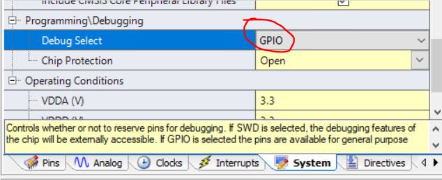
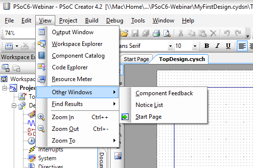
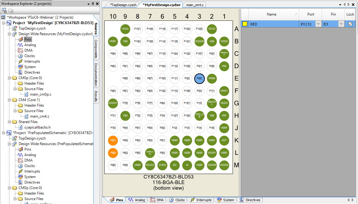
In order to get low power you need to switch the debugging pins off i.e. make them GPIOs. You can do this on the DWR System Screen.
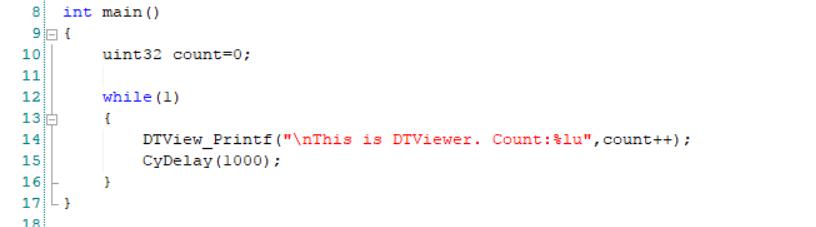
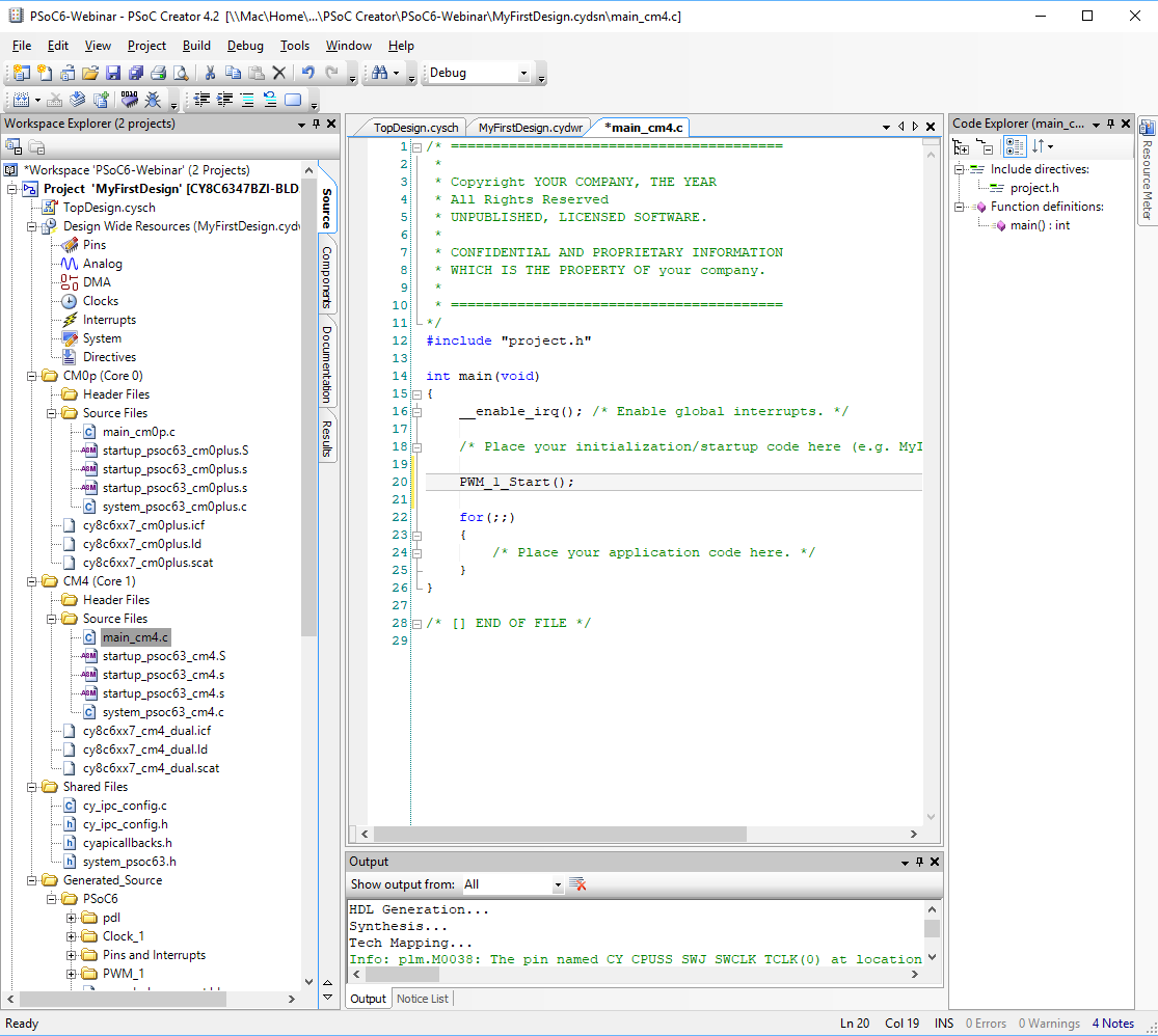
Finally write some firmware. The firmware simply
- Blinks the LED 10 times
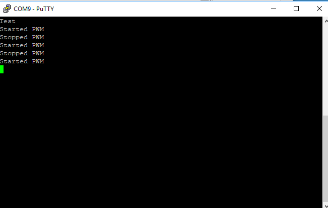
- Prints “Started” to the UART, waits until the buffer is flushed, then turns off the UART to make sure the power is low.
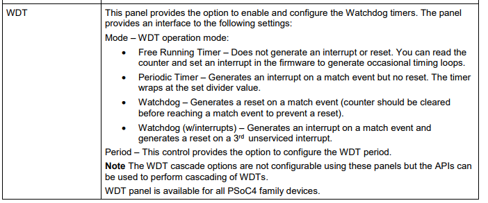
- Configure the Watch Dog Timers. This could have been done on the Low Frequency Clock Screen (except for the cascading of timers which had to be done with firmware)
- Turn off the Pin, Deep Sleep the chip… and wait. When an interrupt from the WDT occurs, it calls the ISR (next section)
int main(void)
{
trigger_Write(1); // Measure Startup
// Blink the LED when the PSoC Starts
for(int i=0;i<10;i++)
{
BLUE_Write(~BLUE_Read());
CyDelay(200);
}
BLUE_Write(0);
UART_Start();
UART_UartPutString("Started\n");
isr_1_StartEx(wdtInterruptHandler);
while(UART_SpiUartGetTxBufferSize()); // Wait until the UART has flushed - then turn off the power
UART_Stop();
CySysWdtUnlock(); // Enable modification of the WDT Timers
// Turn off the WDTs (all three of them)
CySysWdtDisable(CY_SYS_WDT_COUNTER0_MASK);
CySysWdtDisable(CY_SYS_WDT_COUNTER1_MASK);
CySysWdtDisable(CY_SYS_WDT_COUNTER2_MASK);
// Make Timer 0 & 1 run with no interrupt, and 2 cause an interrupt
CySysWdtSetMode(CY_SYS_WDT_COUNTER0,CY_SYS_WDT_MODE_NONE);
CySysWdtSetMode(CY_SYS_WDT_COUNTER1,CY_SYS_WDT_MODE_NONE);
CySysWdtSetMode(CY_SYS_WDT_COUNTER2,CY_SYS_WDT_MODE_INT);
// Set the time to 32768/(64*64*2^6) = 32768/(2^18) = 0.125 = 1/8 Hz
CySysWdtSetMatch(CY_SYS_WDT_COUNTER0, 64);
CySysWdtSetMatch(CY_SYS_WDT_COUNTER1, 64);
CySysWdtSetToggleBit(6);
CySysWdtSetClearOnMatch(CY_SYS_WDT_COUNTER0,1); // When counter his period reset counter
CySysWdtSetClearOnMatch(CY_SYS_WDT_COUNTER1,1);
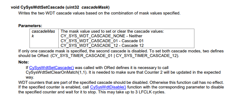
CySysWdtSetCascade(CY_SYS_WDT_CASCADE_01 | CY_SYS_WDT_CASCADE_12); // Cascade 0-1-2
CySysWdtEnable(CY_SYS_WDT_COUNTER0_MASK | CY_SYS_WDT_COUNTER1_MASK | CY_SYS_WDT_COUNTER2_MASK );
trigger_Write(0); // End measurement
CyGlobalIntEnable; /* Enable global interrupts. */
for(;;)
{
trigger_Write(0); // setup trigger
CySysPmDeepSleep(); // wait for interrupt in deep sleep
}
}
The ISR first turns on the trigger pin (which I will use in the next article to trigger the oscilloscope). Then it determines which timer caused the interrupt. Originally I was blinking different color LEDs when I was trying to figure out what was happening. With the current configuration WDT0 and WDT1 will never trigger an interrupt. Finally it clears the interrupt and returns. When it returns the main loop will turn off the trigger pin and then deep sleep.
void wdtInterruptHandler()
{
    trigger_Write(1); // Chip is woken up
    uint32 reason = CySysWdtGetInterruptSource();

    if(reason & CY_SYS_WDT_COUNTER0_INT)
        RED_Write(~RED_Read());

    if(reason & CY_SYS_WDT_COUNTER1_INT)
        GREEN_Write(~GREEN_Read());

    if(reason & CY_SYS_WDT_COUNTER2_INT)
        BLUE_Write(~BLUE_Read());

    CySysWdtClearInterrupt(reason);  // Clear the WDT Interrupt
}
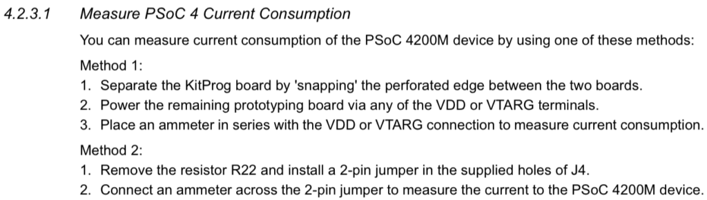
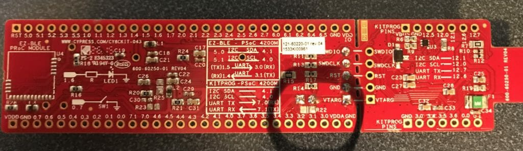
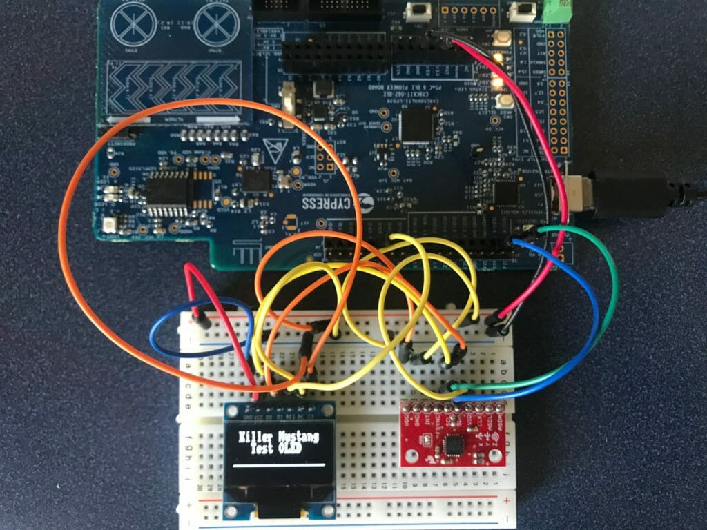
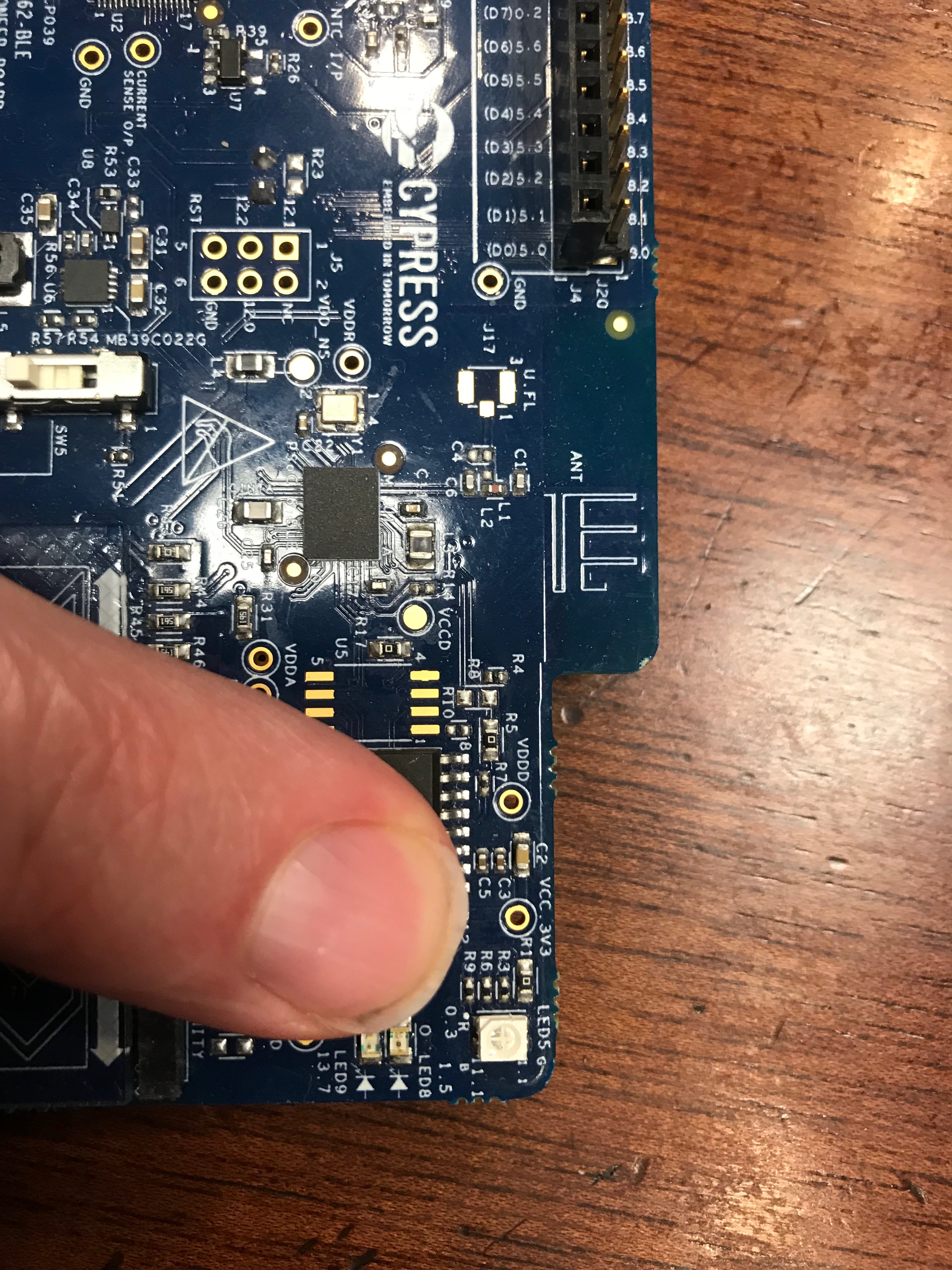
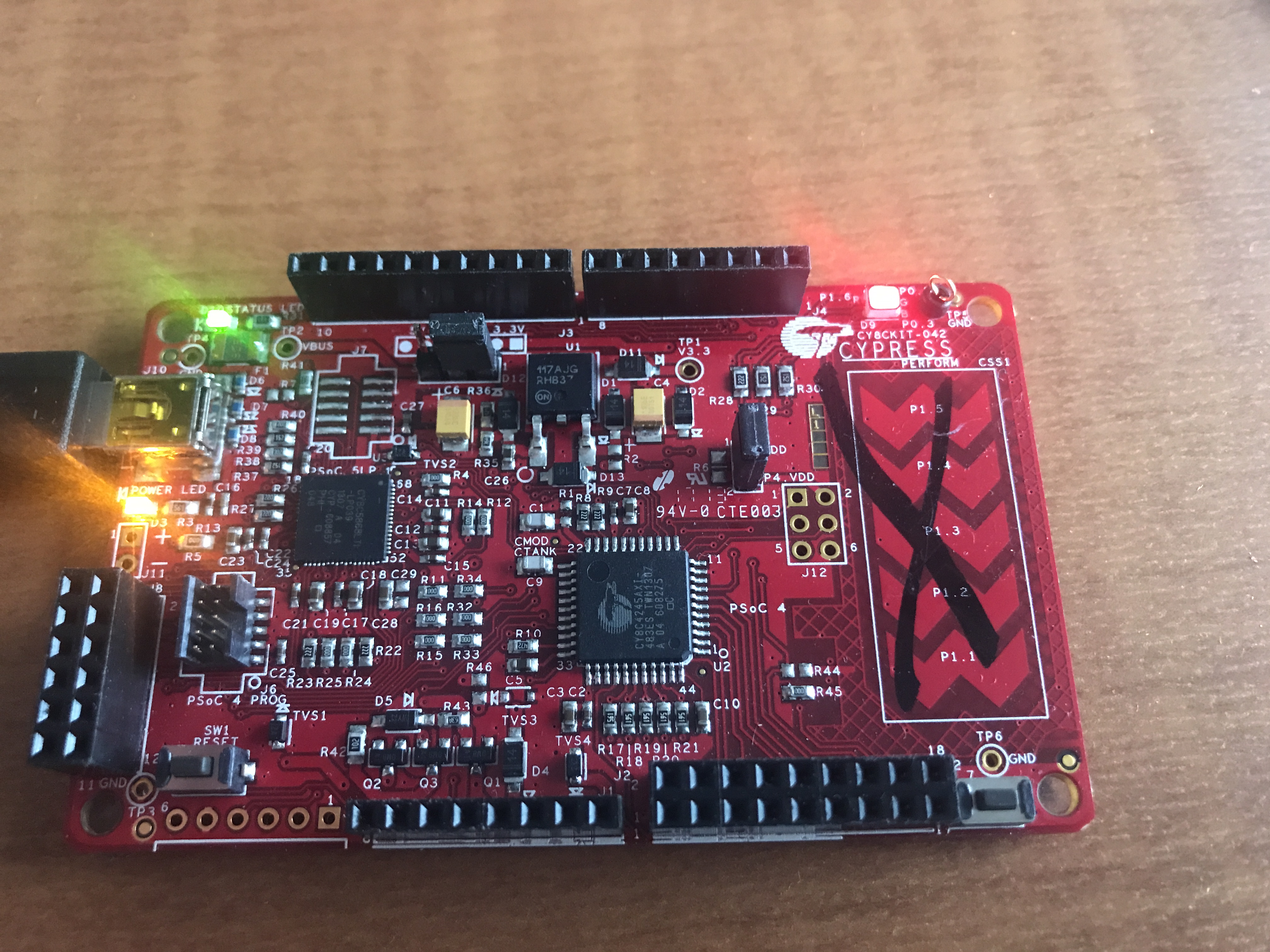
Modified the CY8CKIT-043
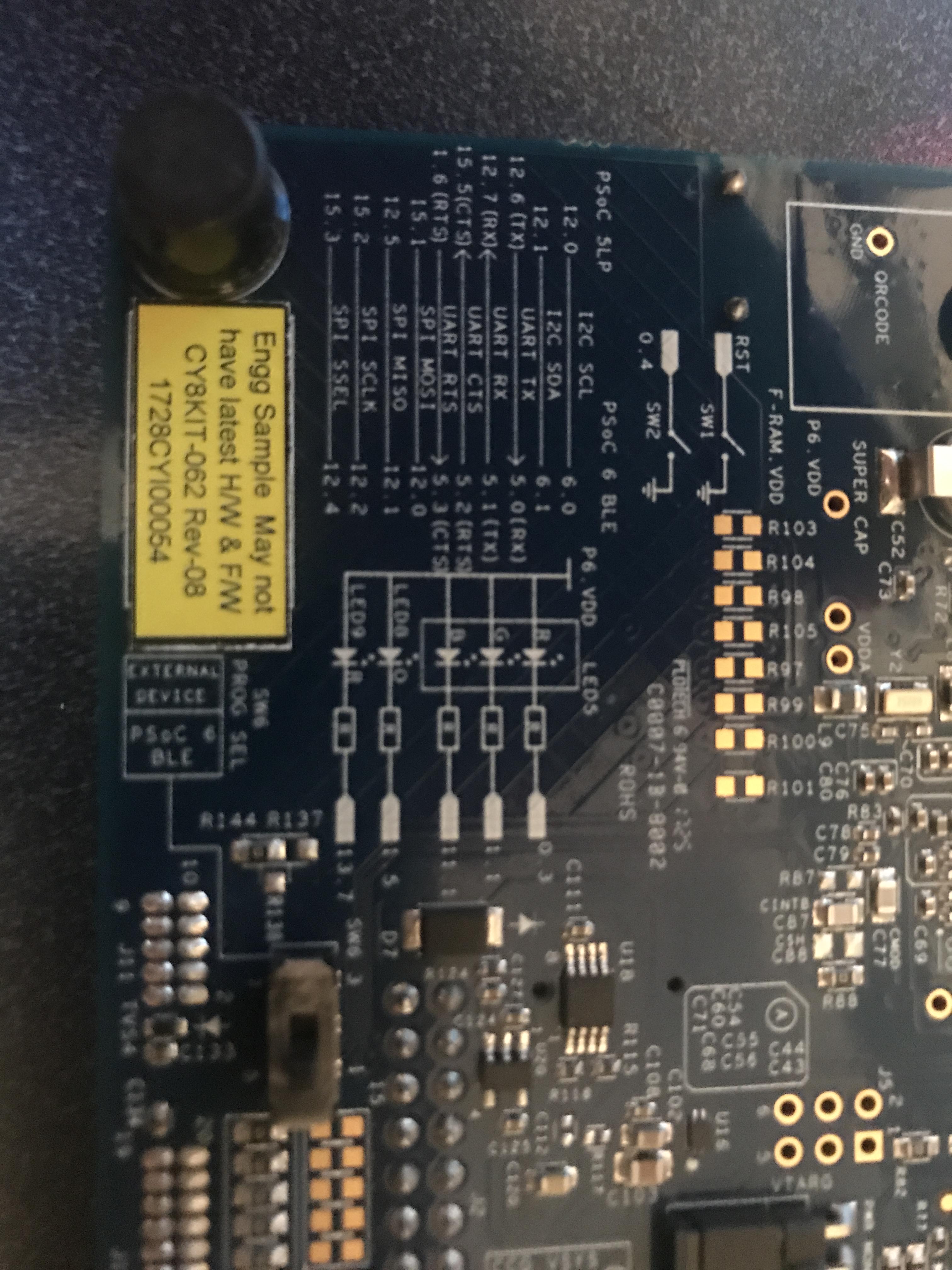
In order to measure current with the. CY8CKIT-043 you need to remove the 0 ohm resistor R22 and install a jumper (J4) so that you can measure the current into the board.

R22 is on the back of the development kit. You can see that I circled it.
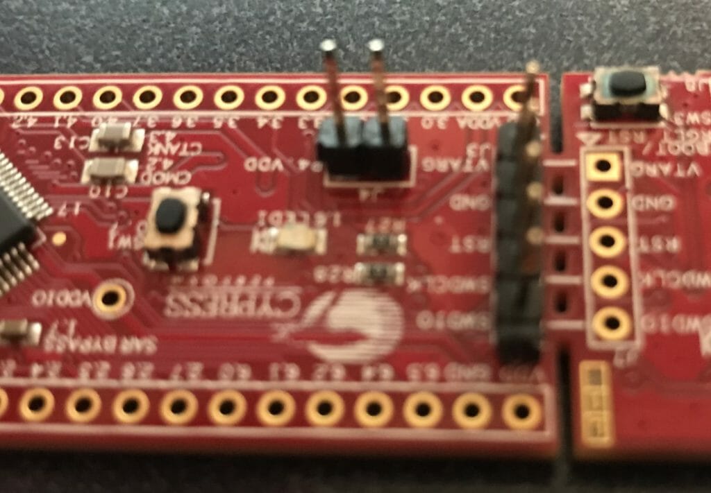
Then install a jumper into J4. I just use a two pin break away header.
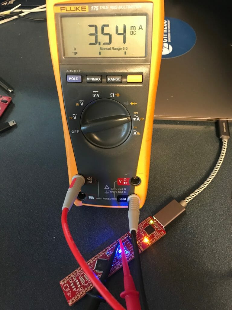
Fluke 175
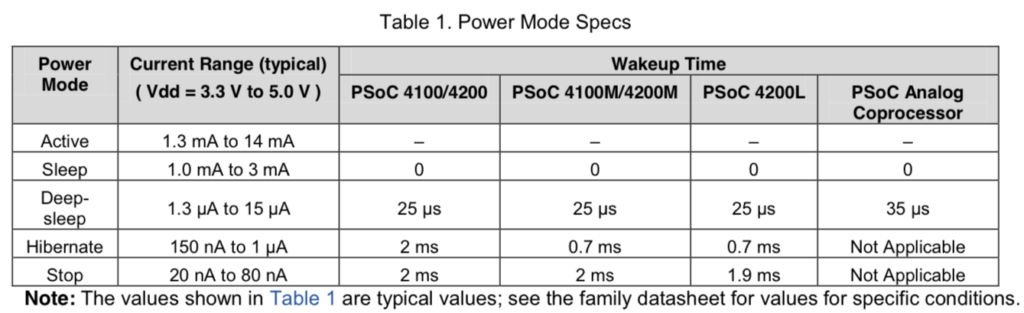
According to the AN 86233 PSoC® 4 and PSoC Analog Coprocessor Low-Power Modes and Power Reduction Techniques I should be able to get 1.3uA in deep sleep 1.3mA in active.
I started with my trusty Fluke 175… but quickly realized that uA are not in the cards. It appears that the lowest it can measure is 10’s of microamps.
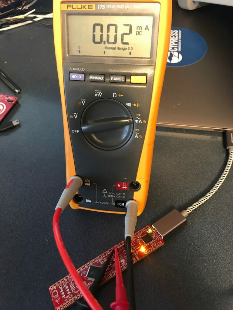
It does fine with the active mode.
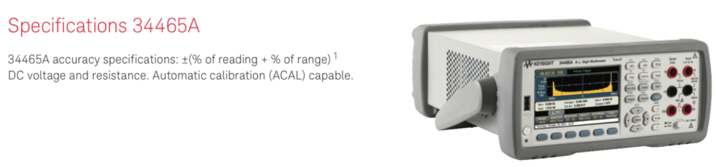
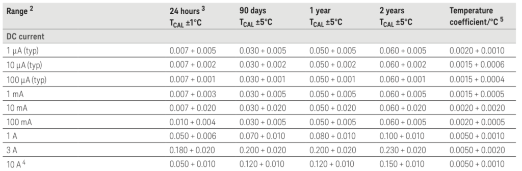
Keysight 34465A 6 1/2 Digit Multimeter
The good news is that I also have a Keysight 34465A 6/12 digit multimeter. In the 1uA range it can measure +- 0.055% of 1uA or about 5nA (is that right?)
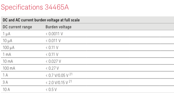
It also doesnt change the input power supply very much. In fact only 0.0011v in 3.3v is negligible.
PSoC 4200M Low Power Current Measurement
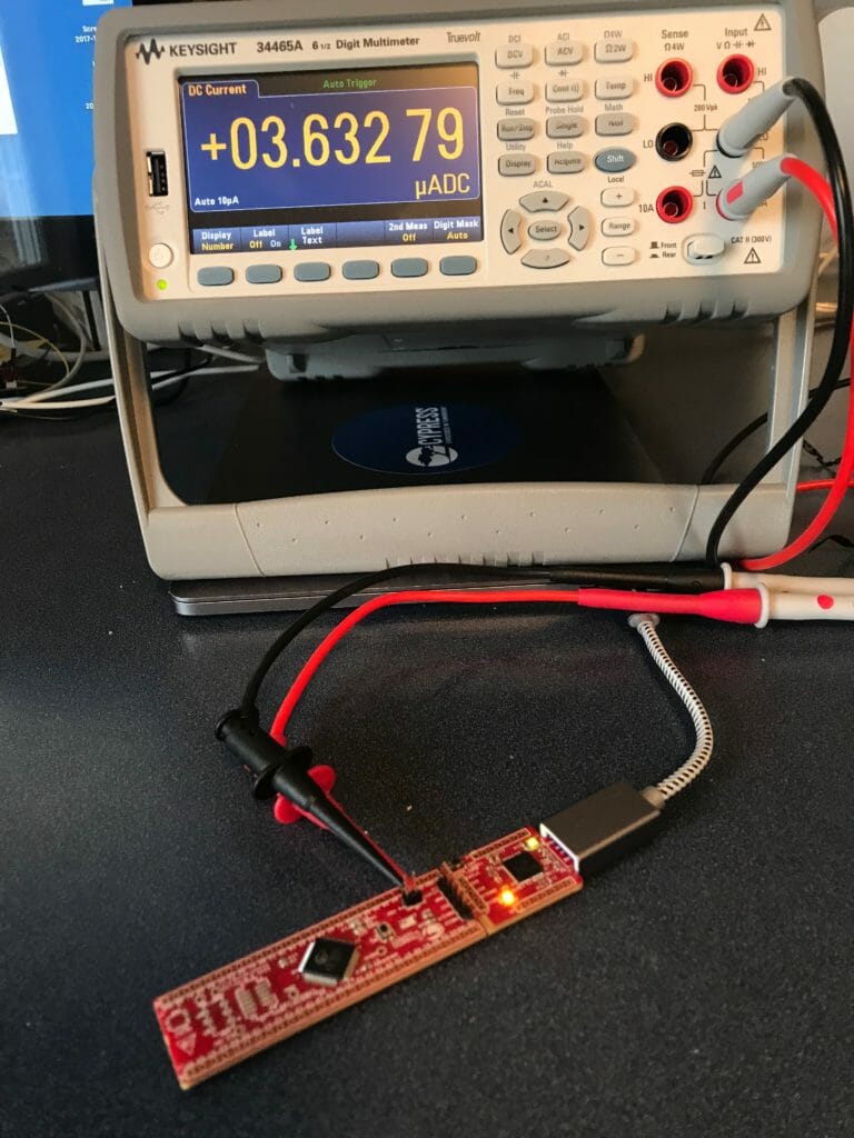
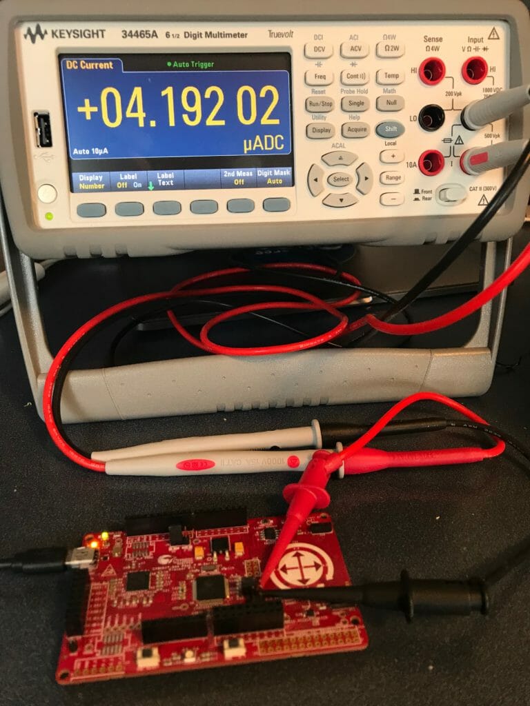
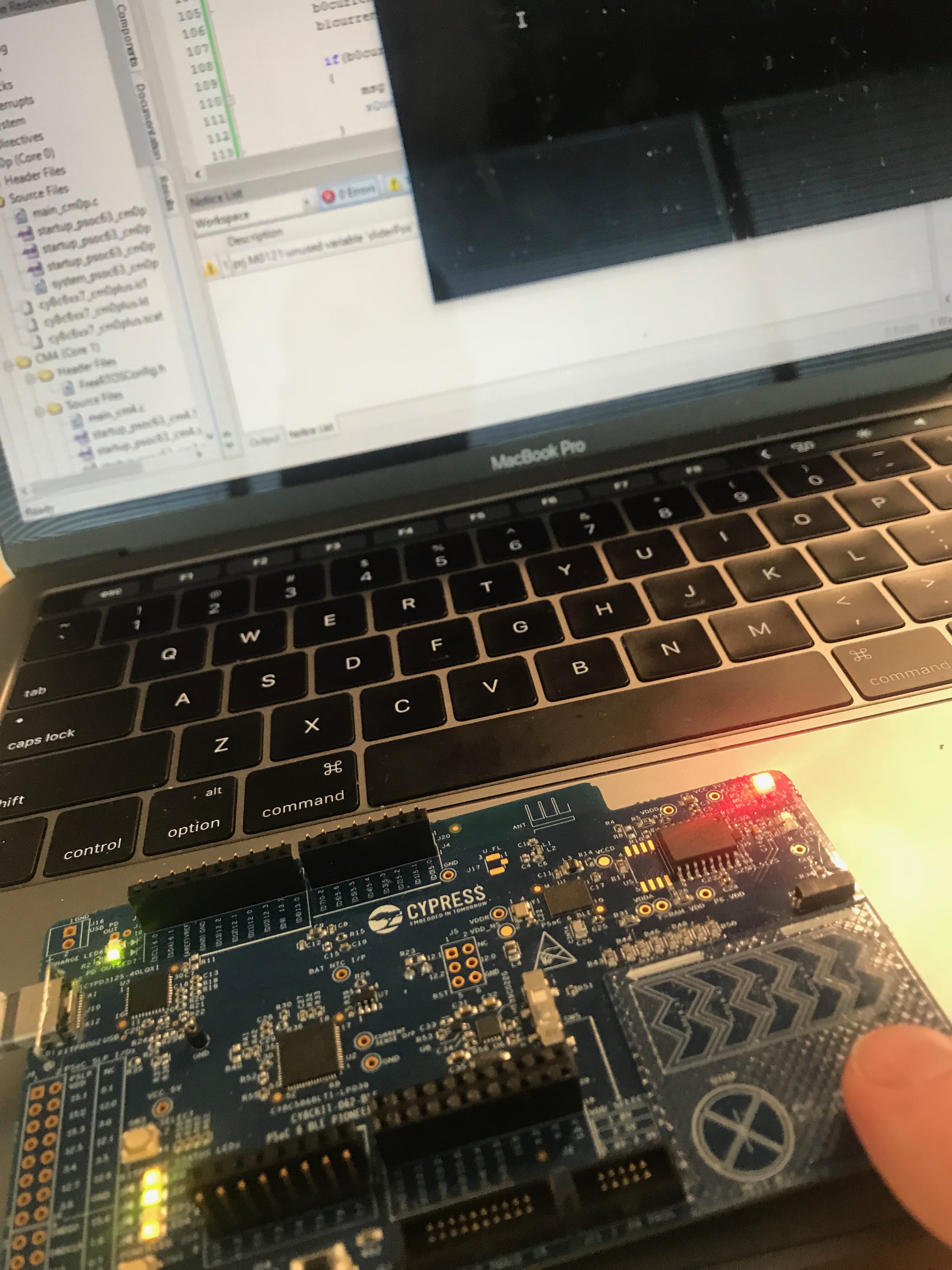
I wanted to measure Active, Sleep, Deep Sleep on the CY8CKIT-043 and CY8CKIT-44 with the WCO on and off. In the two pictures below you can see that the system is taking between 3.6uA and 4.2uA in Deep Sleep.
Here are tables with all of the measurements.
5V – CY8CKIT-044
| Mode | WCO On | WCO Off |
|---|---|---|
| Active | 12..860mA | 12.859mA |
| Sleep | 5.339mA | 5.335mA |
| Deep Sleep | 4.206uA | 1.078uA |
3.3V – CY8CKIT-044
| Mode | WCO On | WCO Off |
|---|---|---|
| Active | 12.84mA | 12.84mA |
| Sleep | 5.328mA | 5.327mA |
| Deep Sleep | 4.096uA | 0.940uA |
5V – CY8CKIT-043
| Mode | WCO Off |
|---|---|
| Active | 12.711mA |
| Sleep | 5.352mA |
| Deep Sleep | 3.632uA |
The other thing that is pretty cool with the KeySite is that you can put it into “Trend” mode and it can display the current readings over a long period. In the picture below I am flashing the LED which takes around 3.5mA @ 3.3v on this development kit.
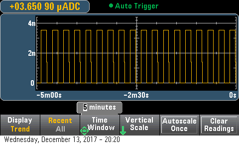


