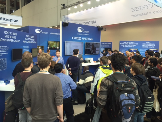
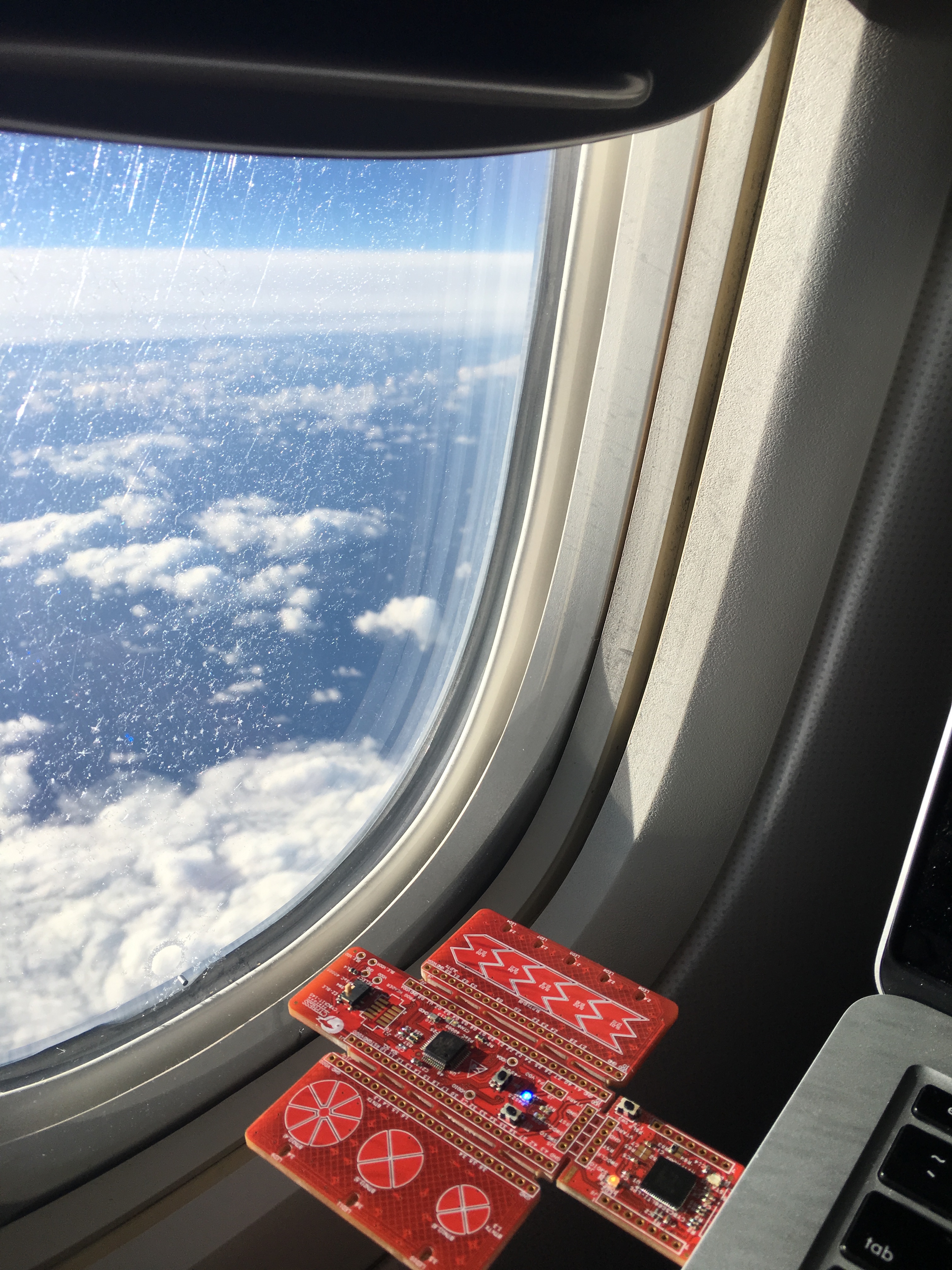
One of the cool things about my job is I get to try out lots of new development kits before they are released to the general public. In the previous post I talked about the demonstration I gave at the Embedded World conference using the CY8CKIT-042 BLE. You can find a complete video tutorial for that project on the cypress.com video tutorial website. While I was at the conference, I picked up an engineering sample of a new development kit and put it into my backpack because I wanted to try a new feature of PSoC Creator on the way home. But, when I got on the airplane, I thought I would build the same project I had demonstrated at the conference using this kit. So, in the next few posts, I am going to show you the new CY8CKIT145 Stamp Board and how to build an IOT solution with it.
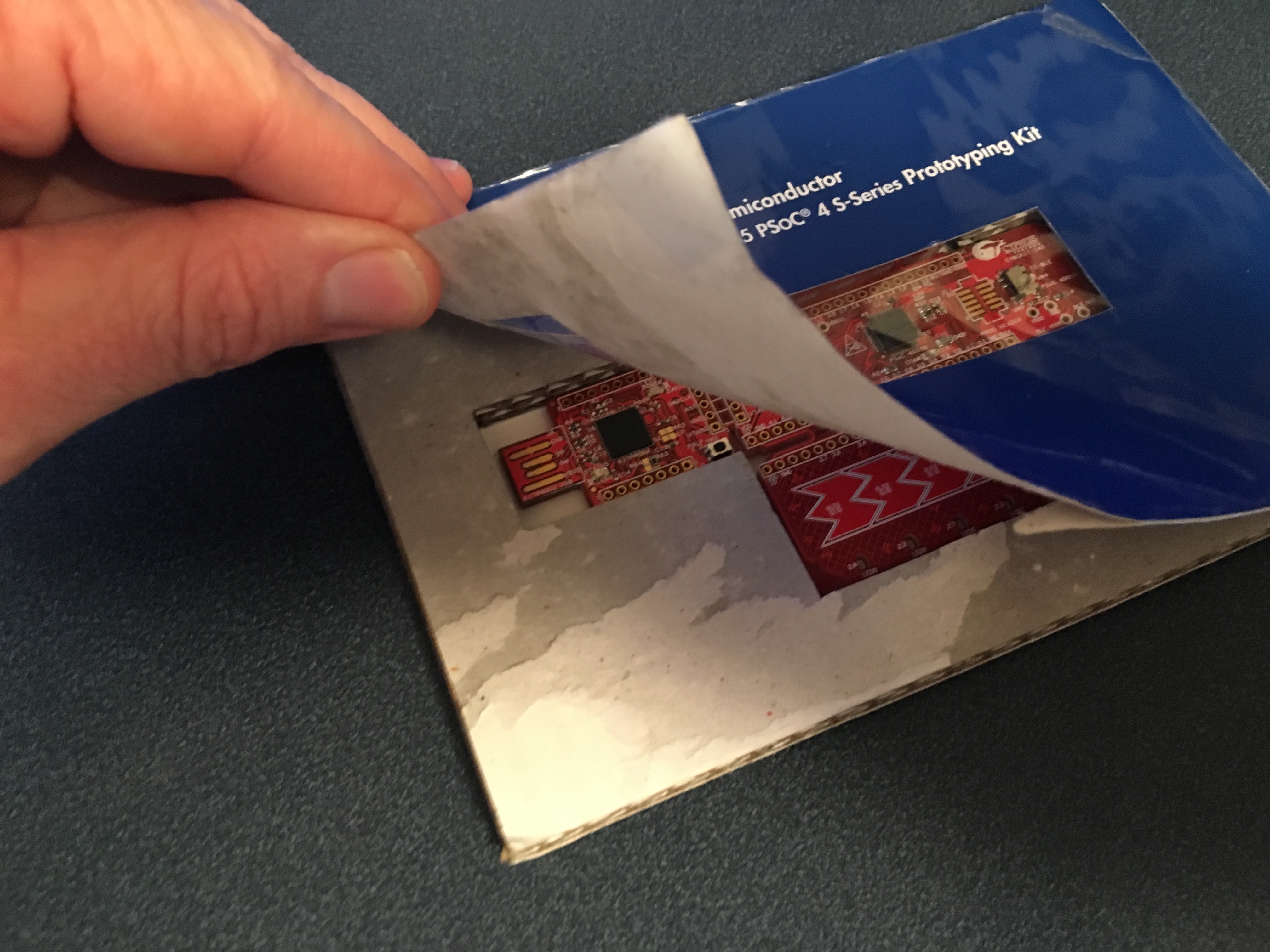
It is called a “stamp board” because it comes in a flat postage stamp-like postcard mailer. Here is a picture of the front and the back (you can see that it has already lived a hard life riding around in my backpack).

Here is the back of the mailer:
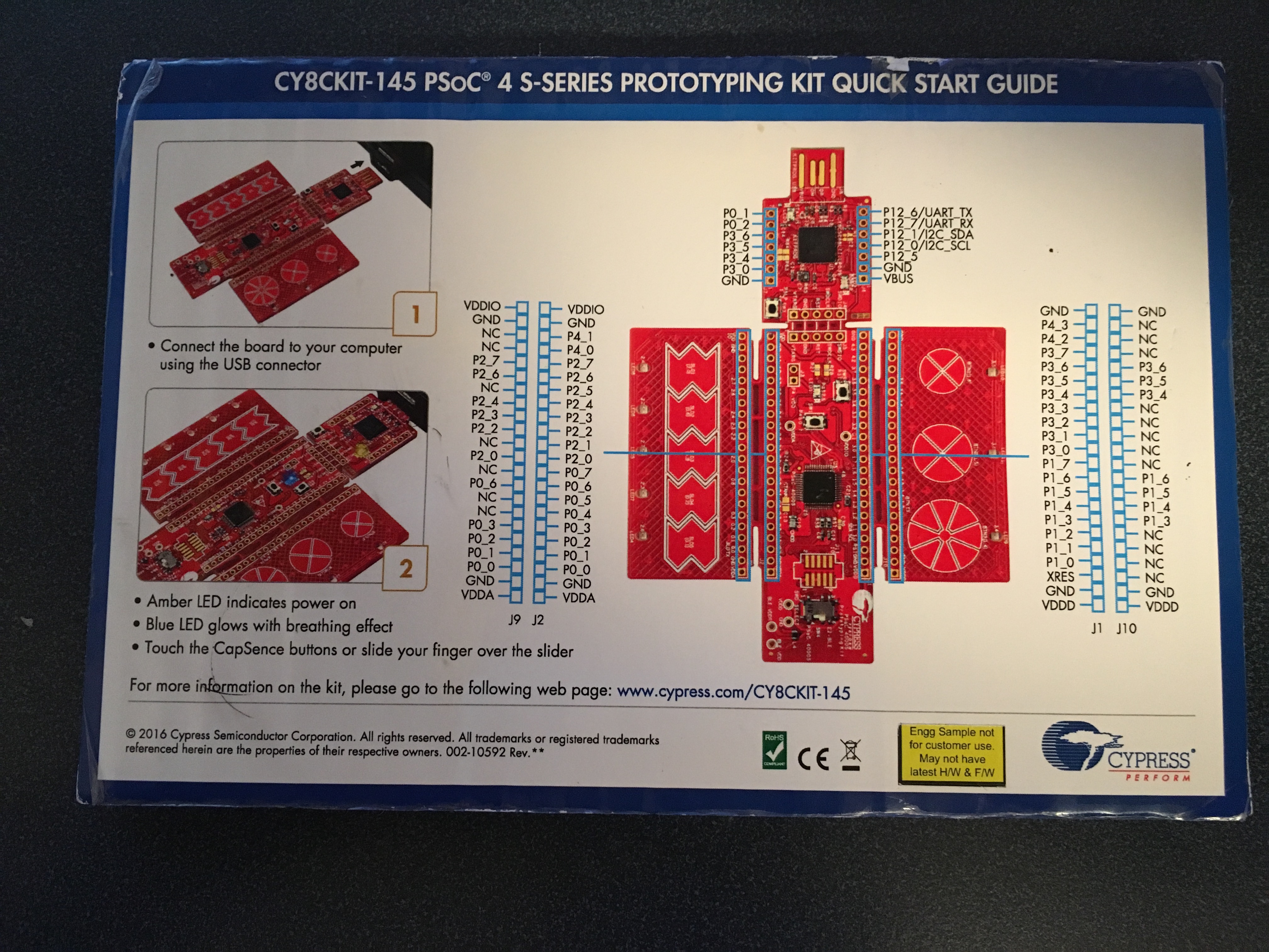
In the picture you can see the yellow label proclaiming this to be an engineering sample. It doesn’t seem like much, but when you pull back the front of the package you get to see the surprise:
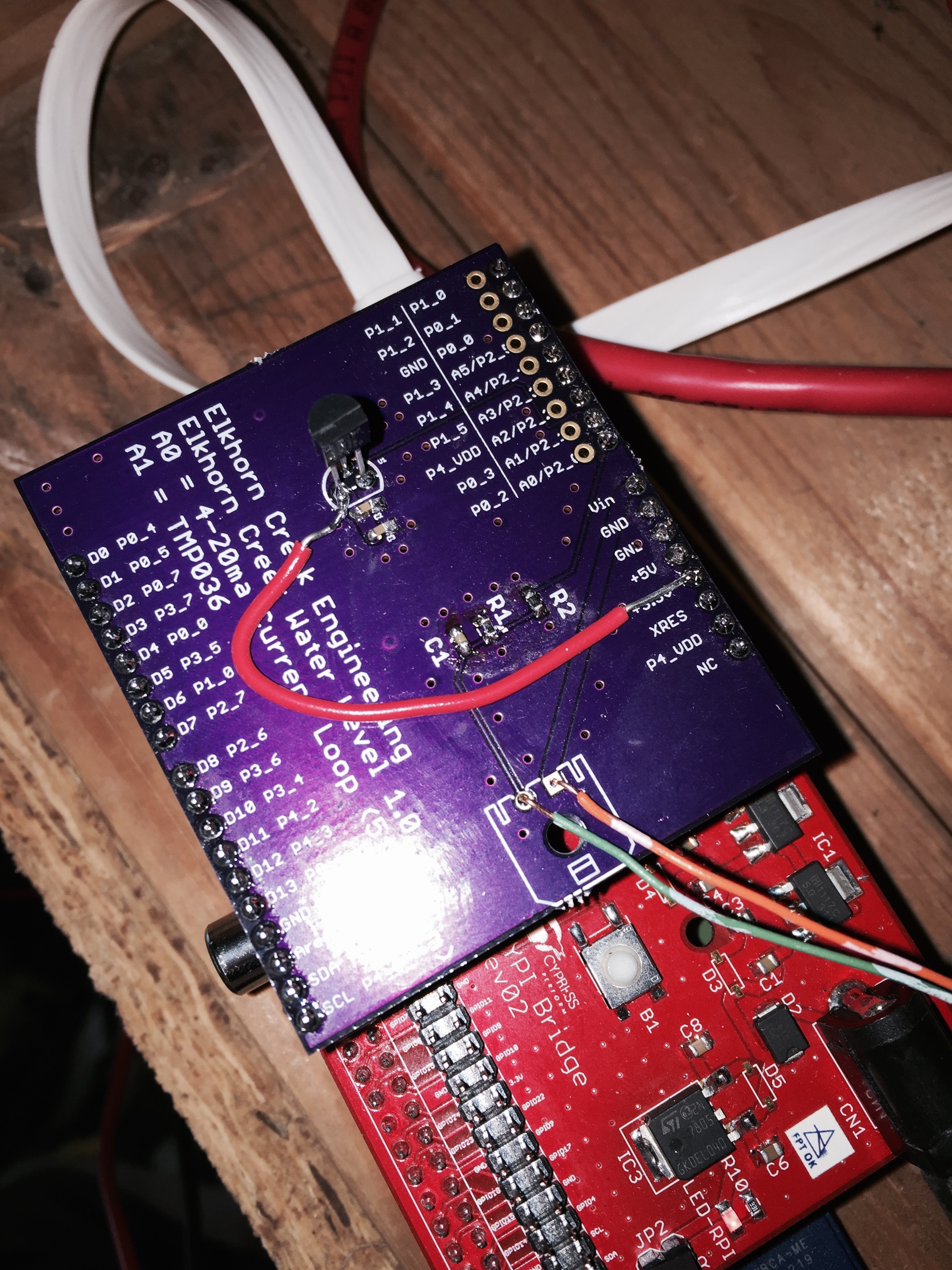
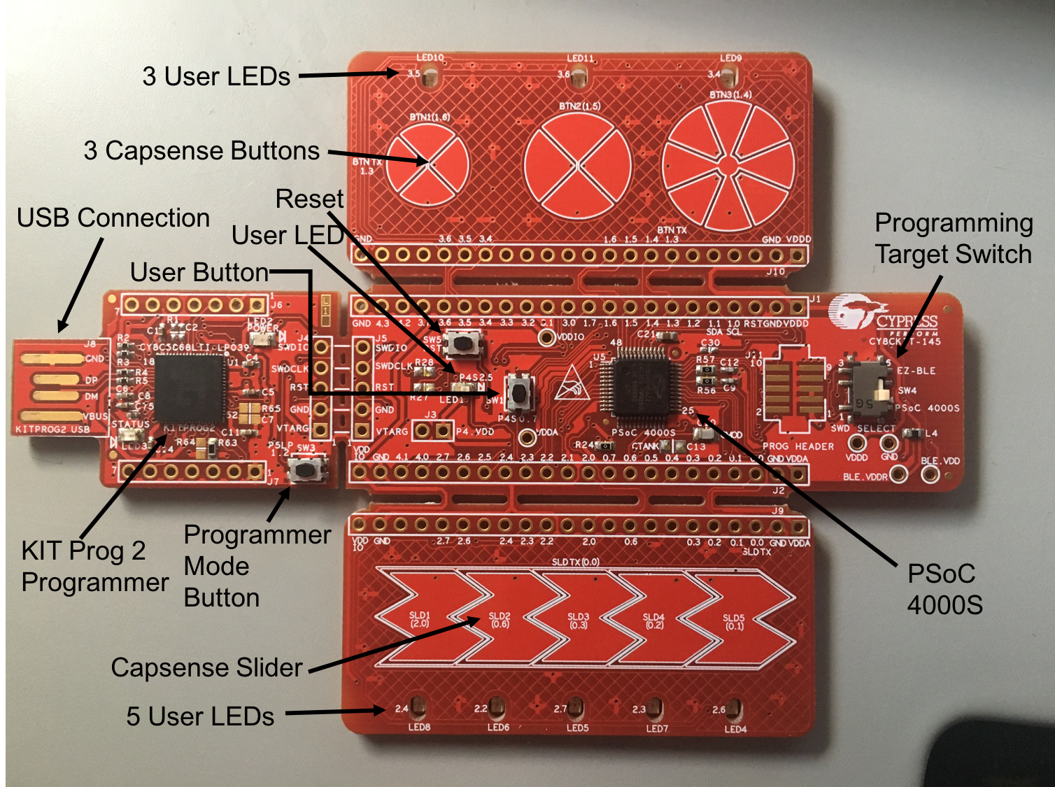
The kit can literally be broken into four separate pieces:
- The main board:
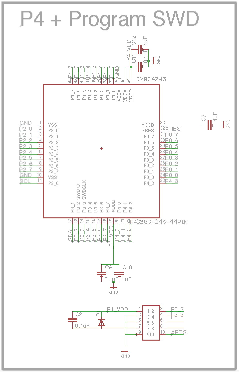
- The PSoC4000S
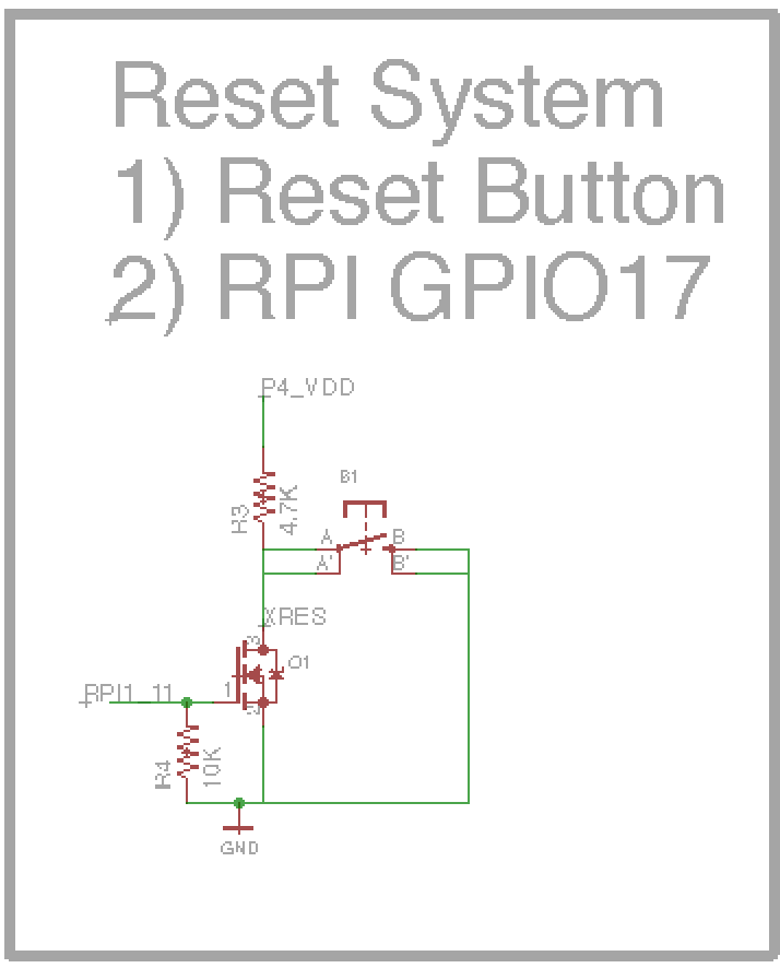
- A reset switch
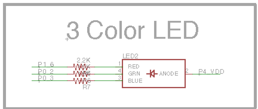
- A user LED
- A user push button
- A programming selector (to pick either the PSoC4000s or the PRoC BLE (that is on the back of the kit)) as the target of the programmer
- All of the PSoC4000S pins are available on the 100mil center headers
- A PCB footprint for a 10-pin ARM programming header
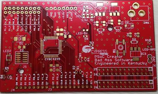
- A programmer board:
- A PSoC5LP programmed with KitProg2 Firmware
- A programmer mode button
- 100mil center header with some of the PSoC5LP pins
- A Capsense slider user interface board with a 5 Segment Slider and 5 LEDs
- A Capsense button user interface board with 3 mutual capacitance buttons and 3 LEDs
And the back, with the tiny 10mm X 10mm PRoC BLE module:

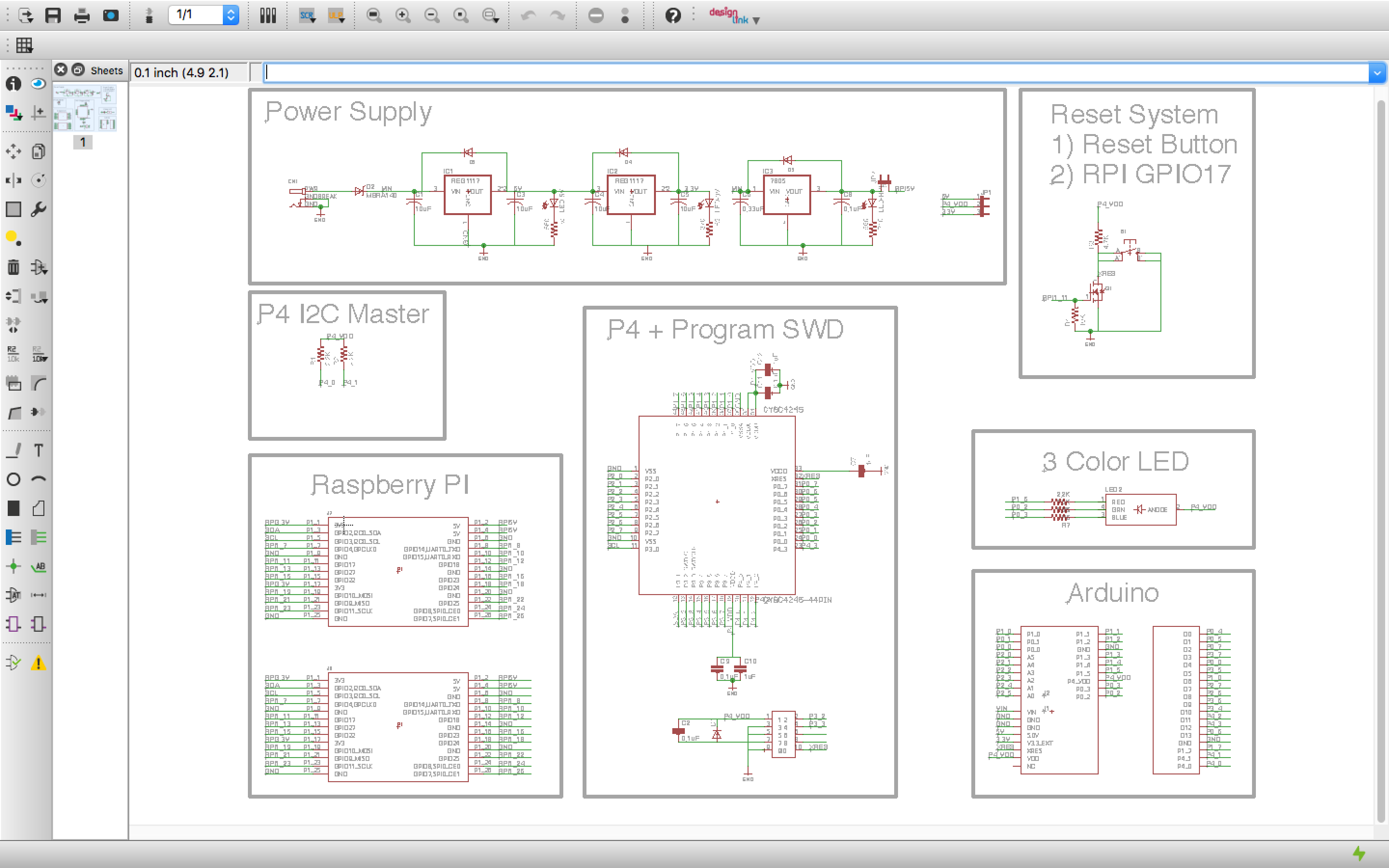
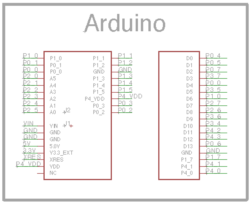
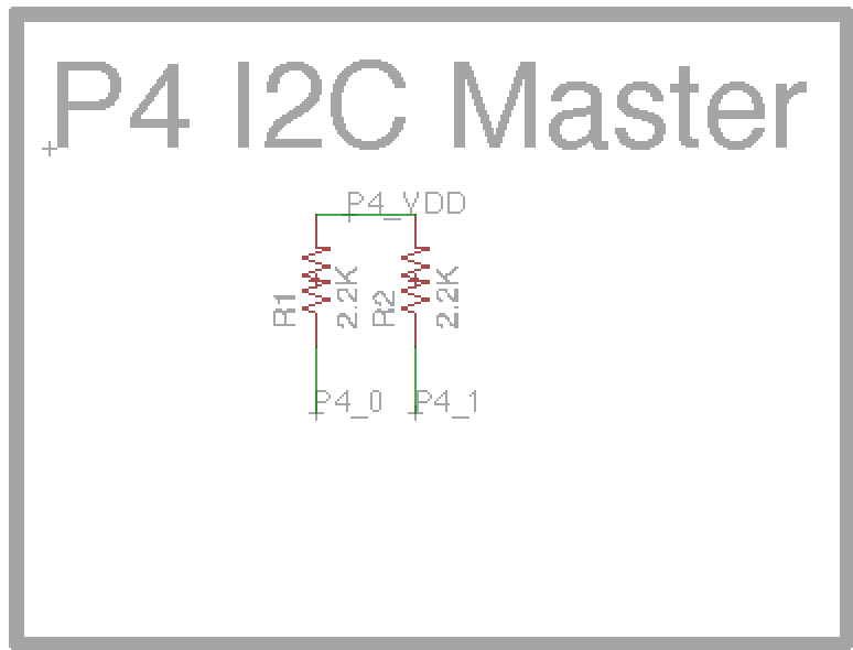
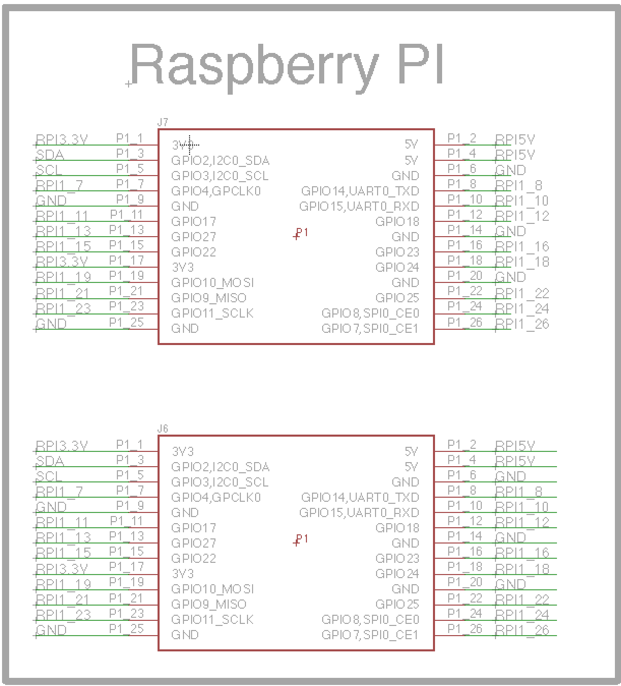
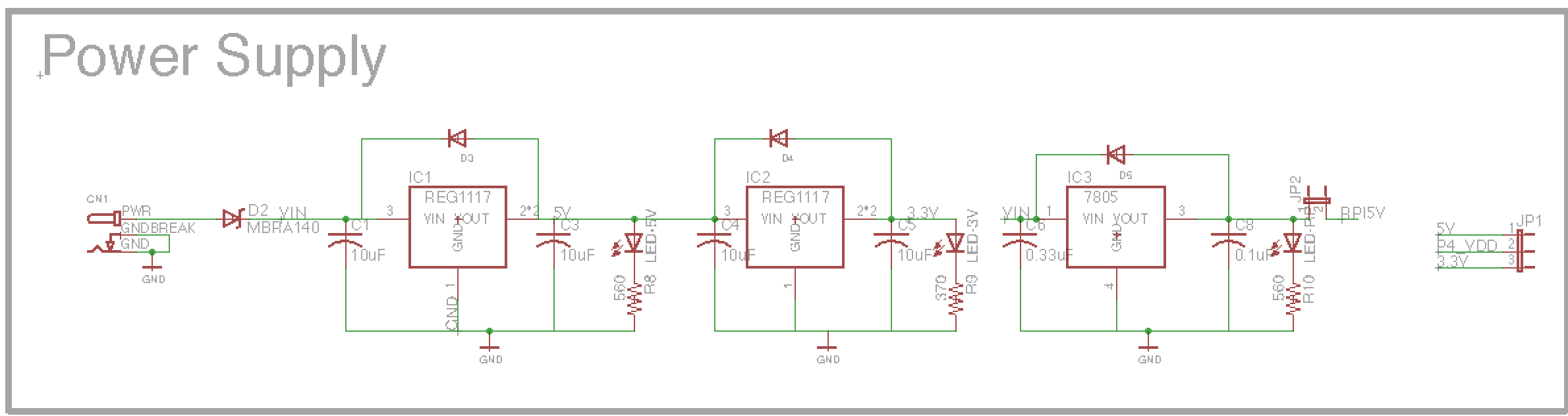
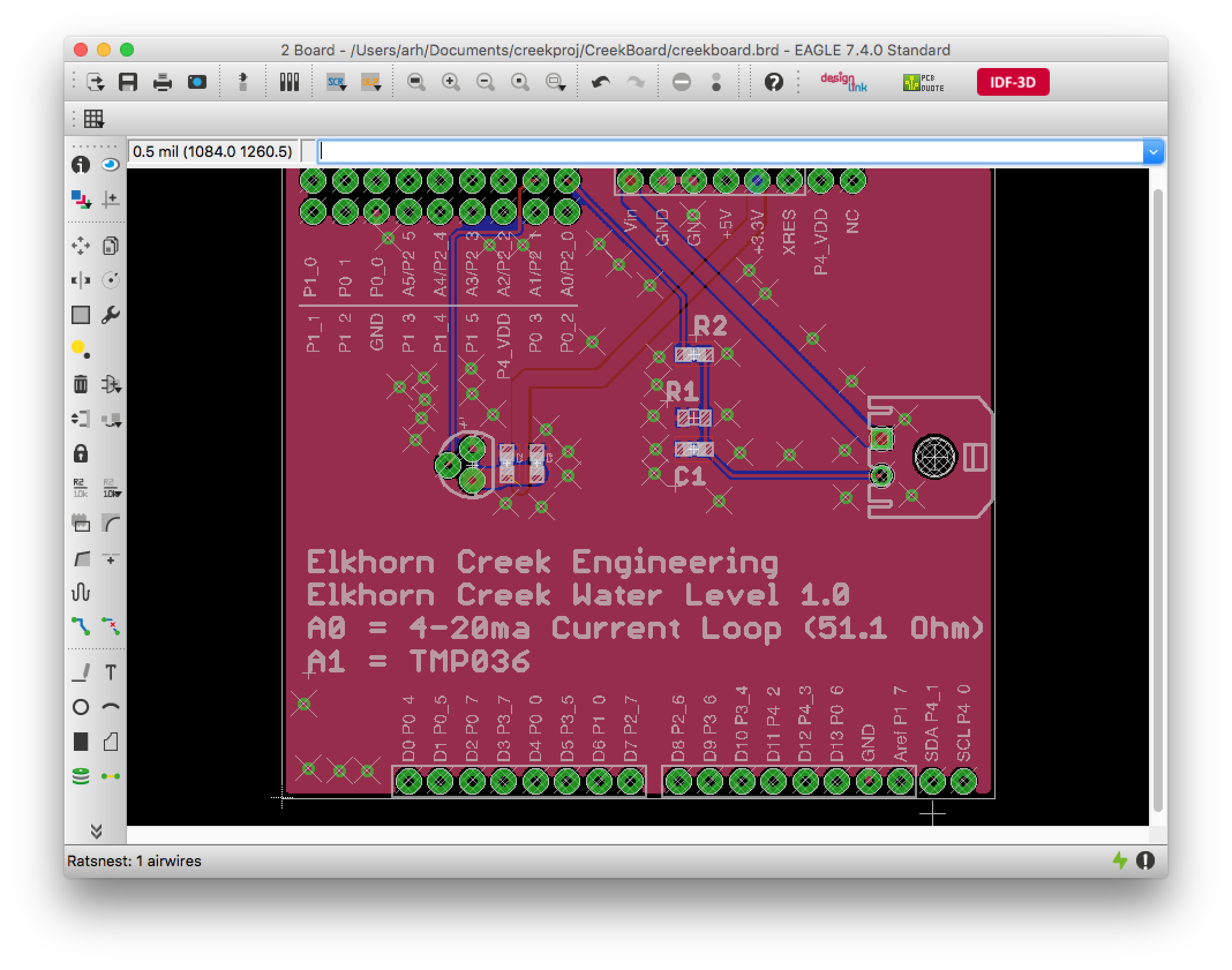
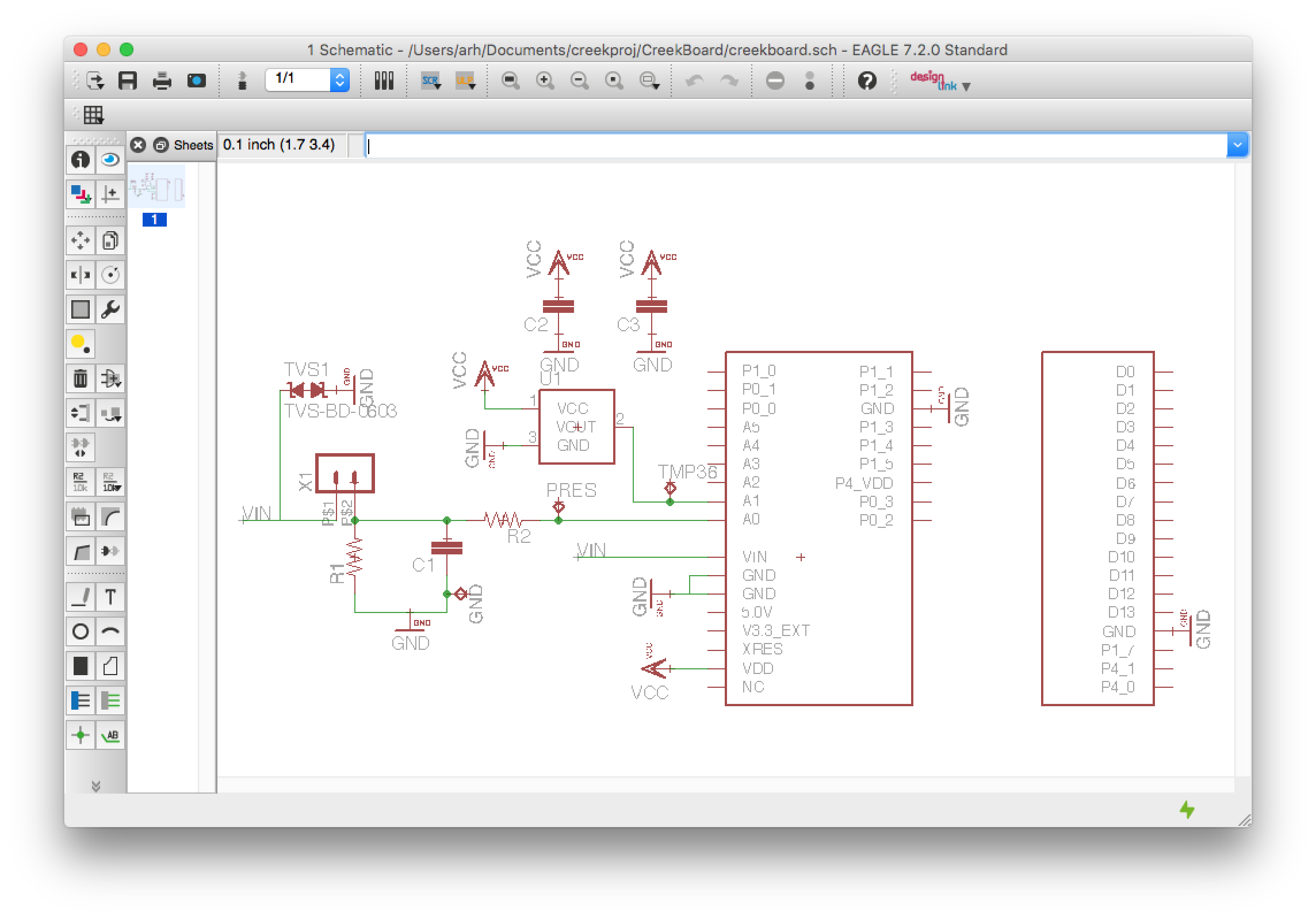
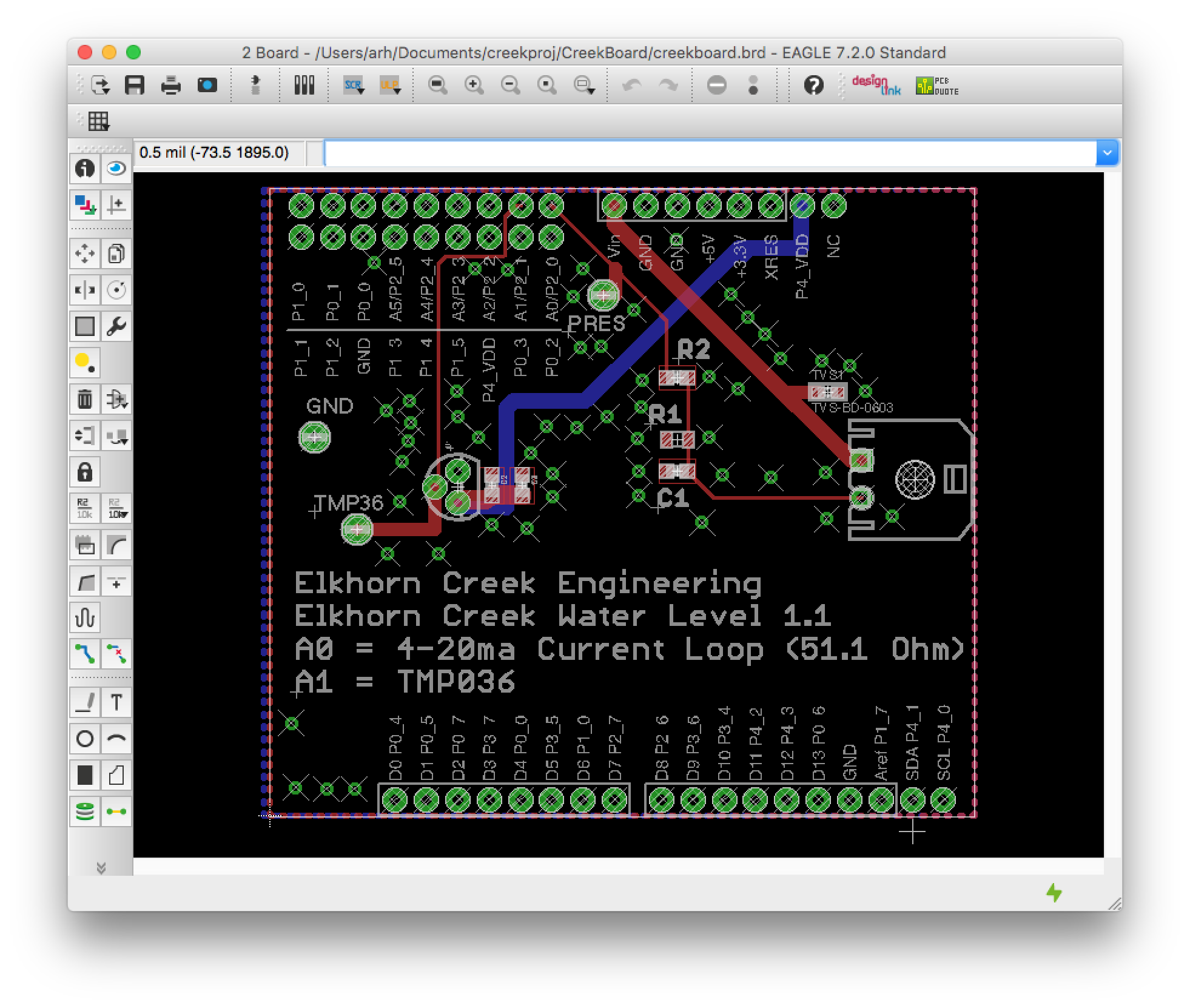
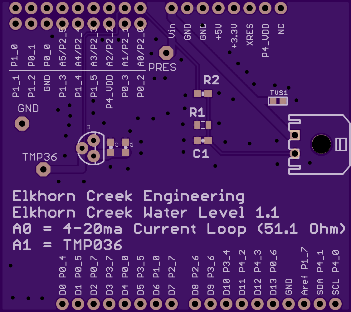
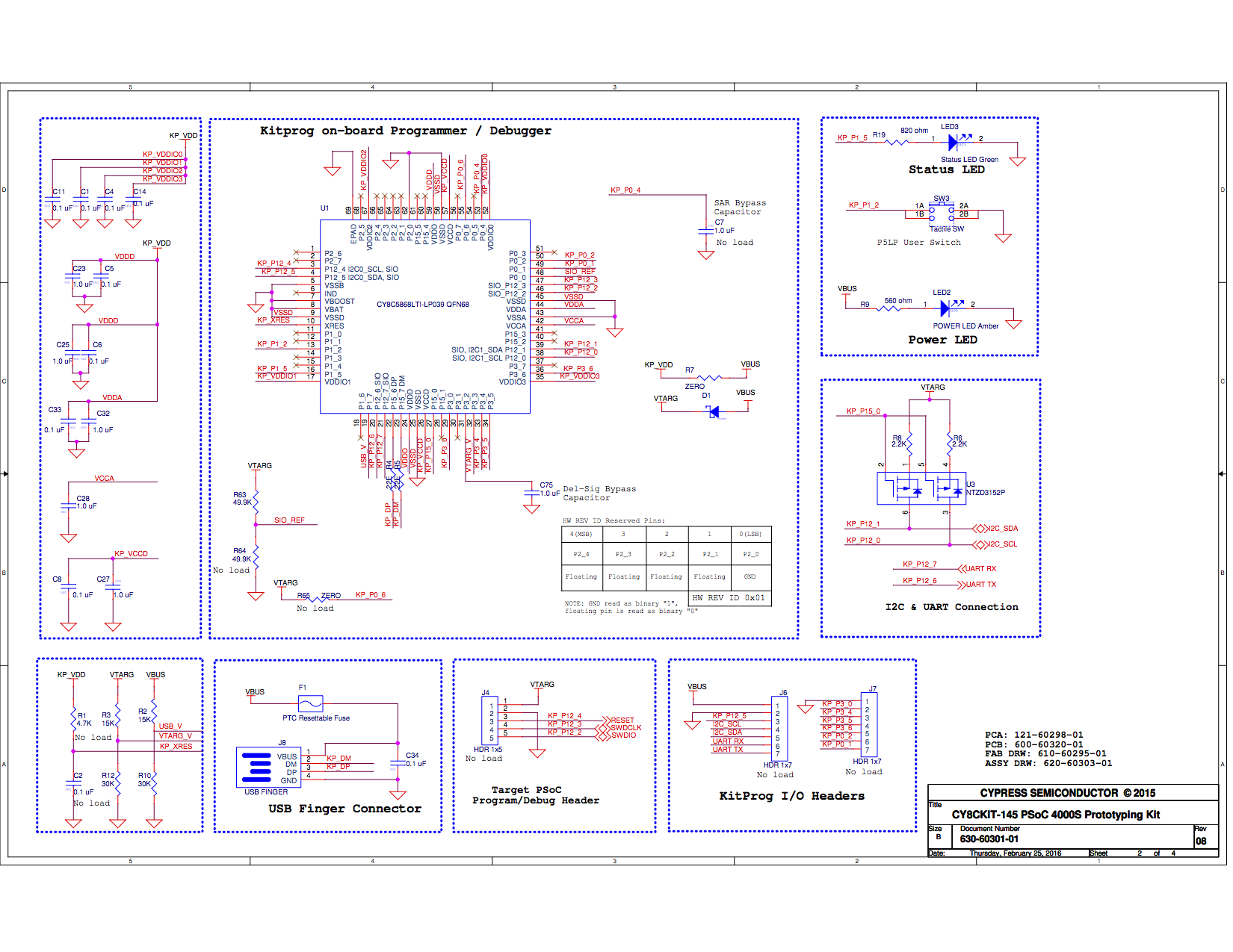
Here is the schematic for the board:


I wanted to build a project that would have two-way communication between my iPhone and the board, and would be compatible with the Swift App I had written. The user of the board would have a capsense slider (and LEDs) of which the iPhone App could read the position. In addition, it would have an LED that the iOS app could turn on and off. Here is a demonstration that I filmed with my iPhone on the airplane:
In the next post I will describe the overall system and show you the firmware.
Index
Description
PSoC4000s and the CY8CKIT145 Stamp Board - Part 1
The board and schematics
PSoC4000s and the CY8CKIT145 Stamp Board - Part 2
PSoC4000S Firmware
PSoC4000s and the CY8CKIT145 Stamp Board - Part 3
PRoC BLE Firmware
PSoC4000s and the CY8CKIT145 Stamp Board - Part 4
Debugging the problem