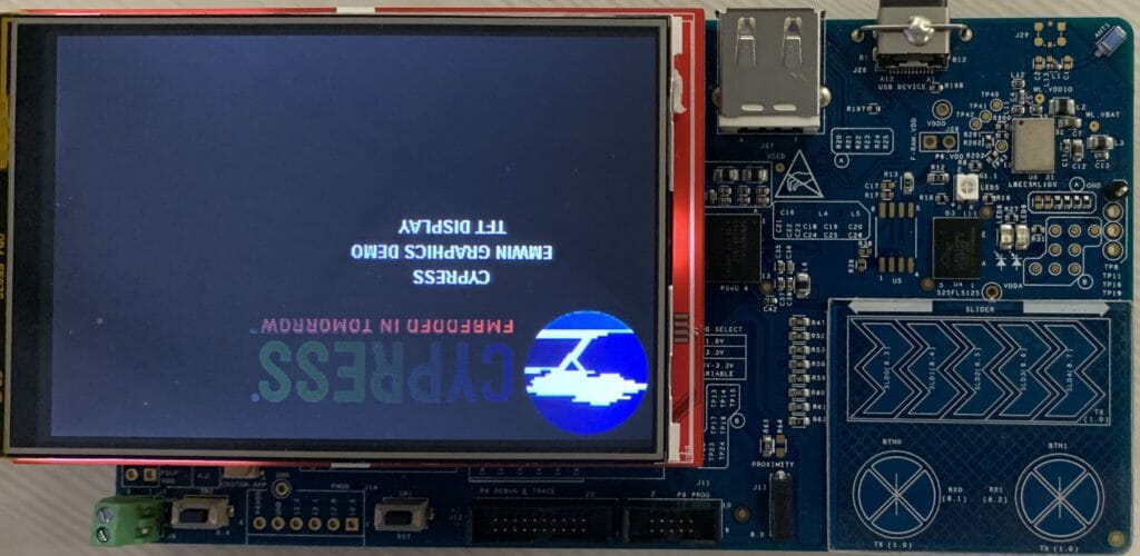
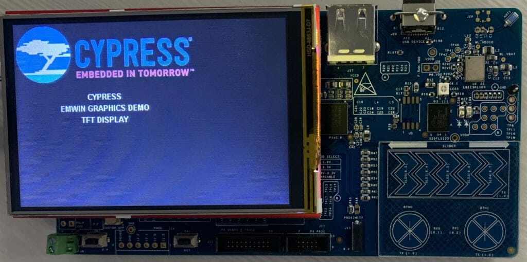
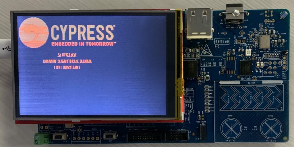
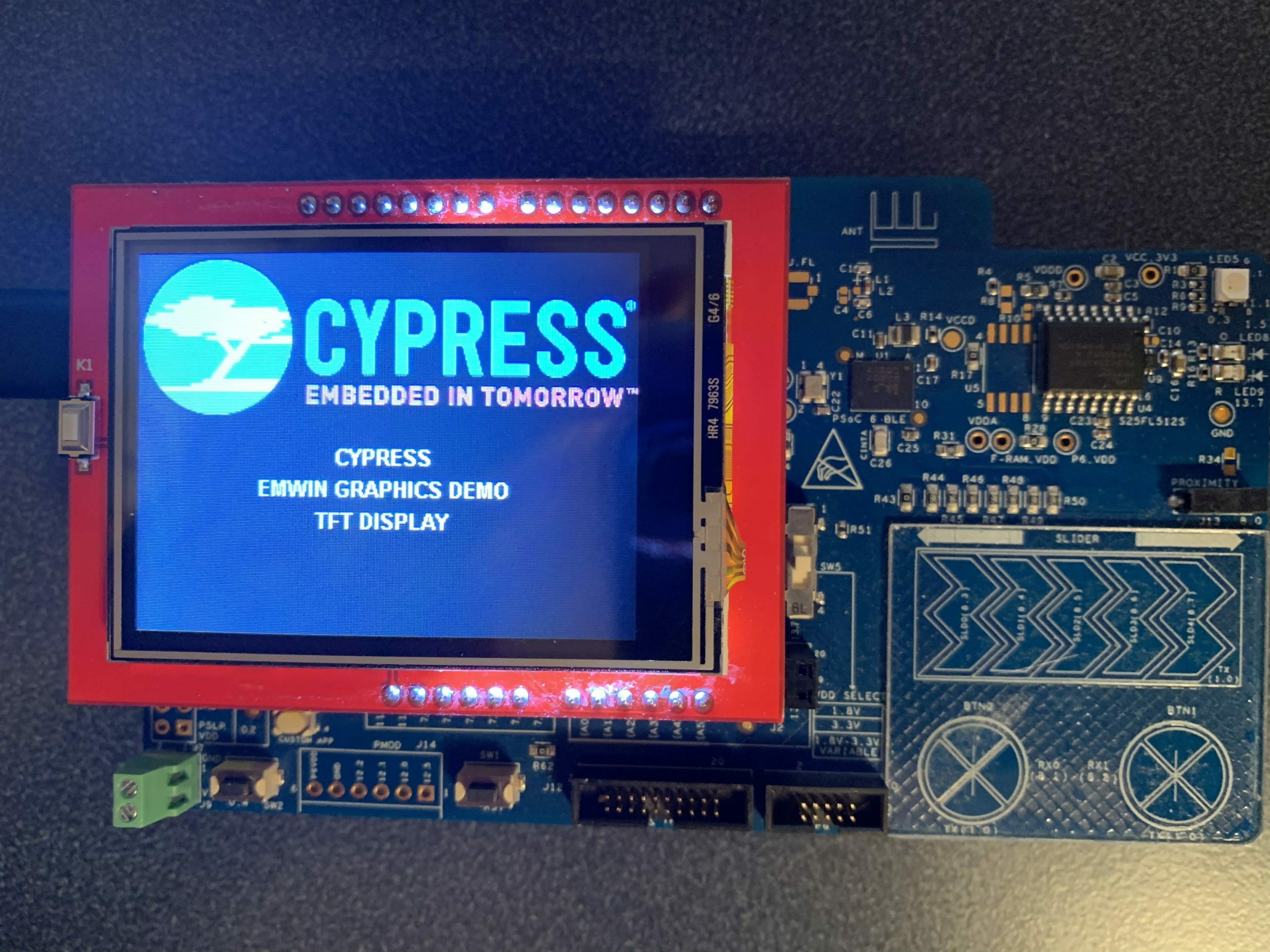
MBED OS & CY8CKIT_062S2_43012 & Segger emWin & NTP

Summary

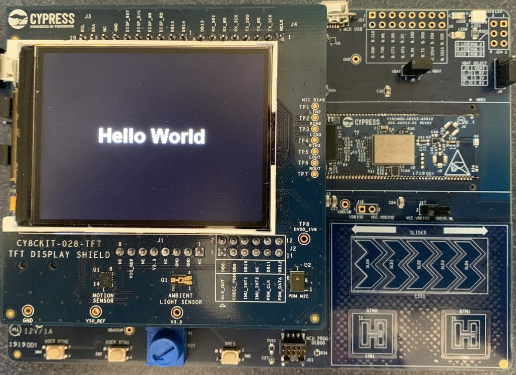
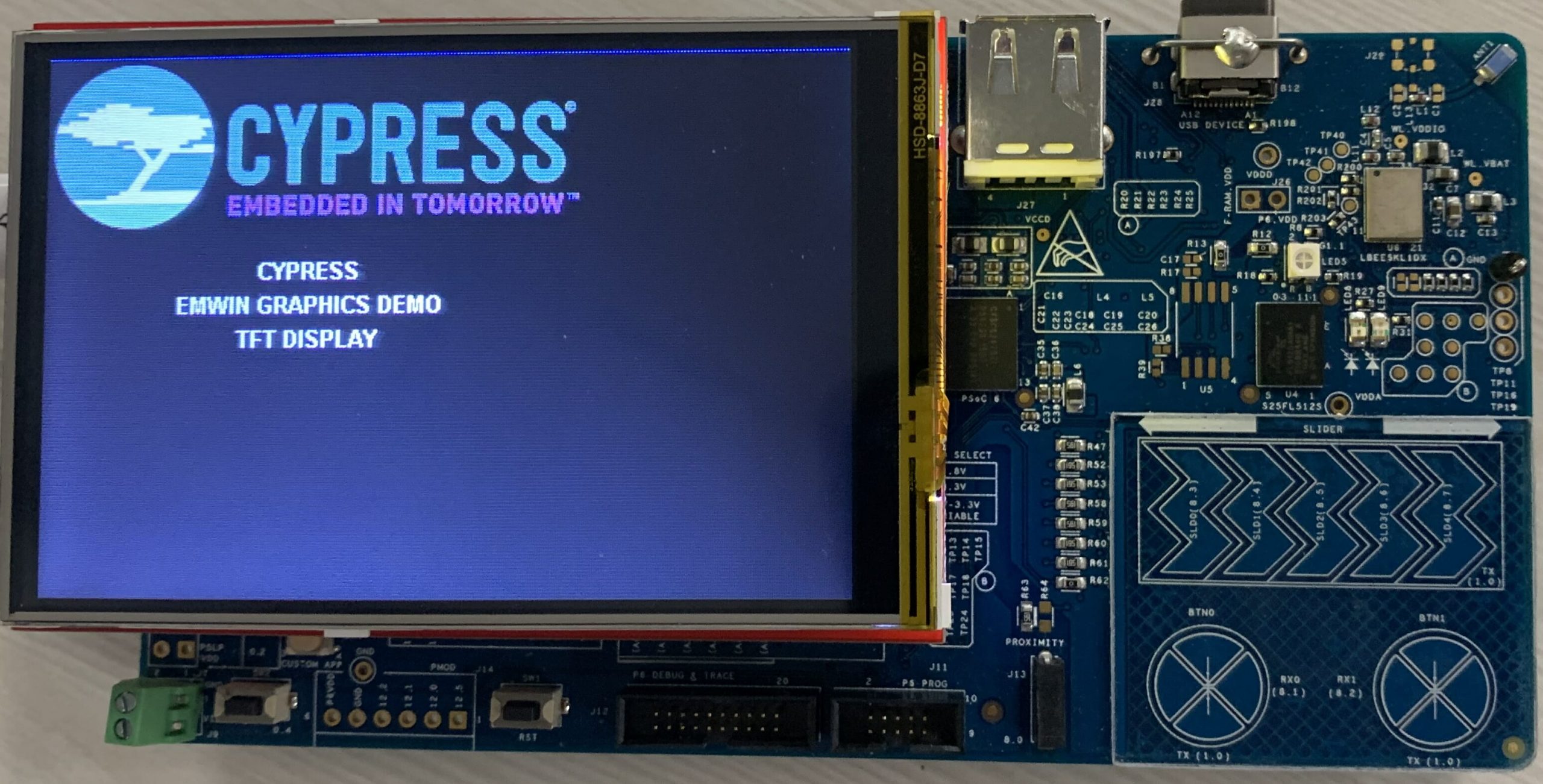
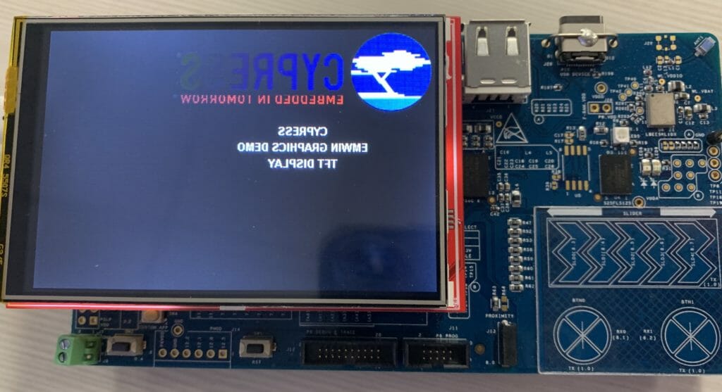
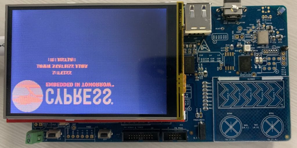
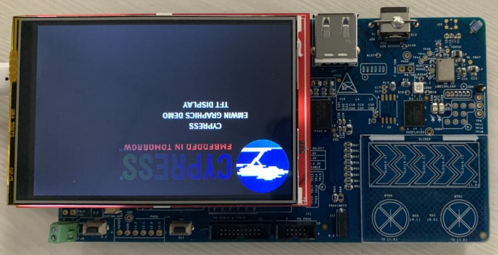
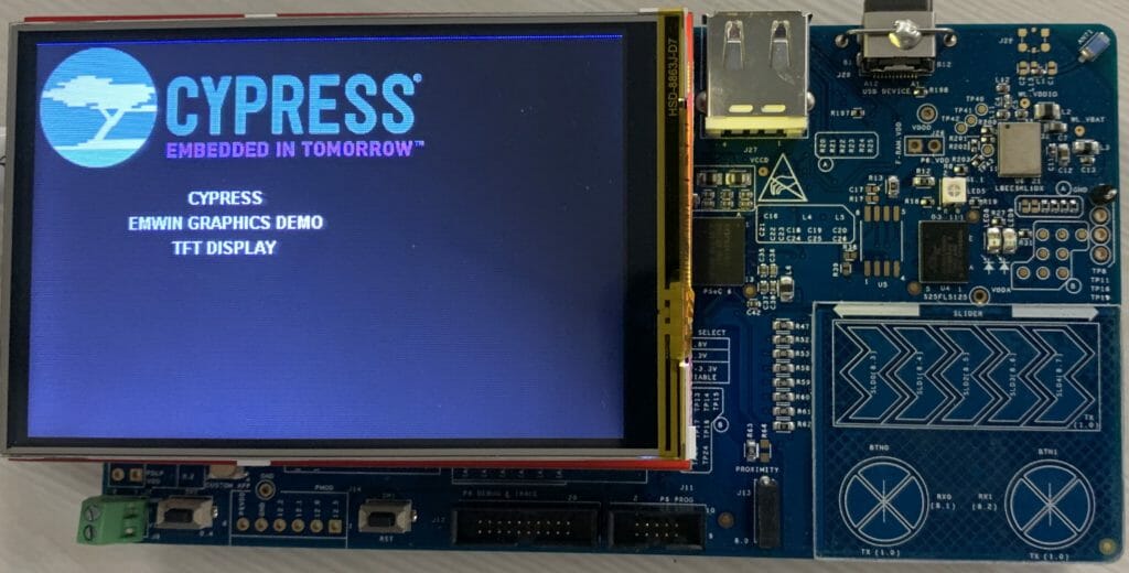
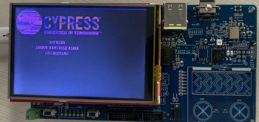
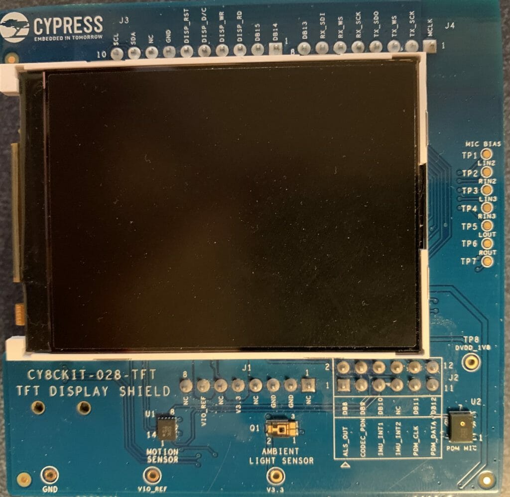
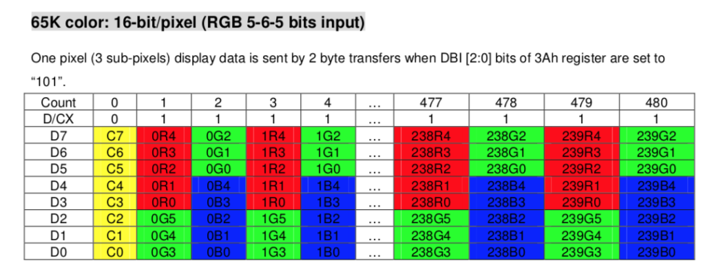
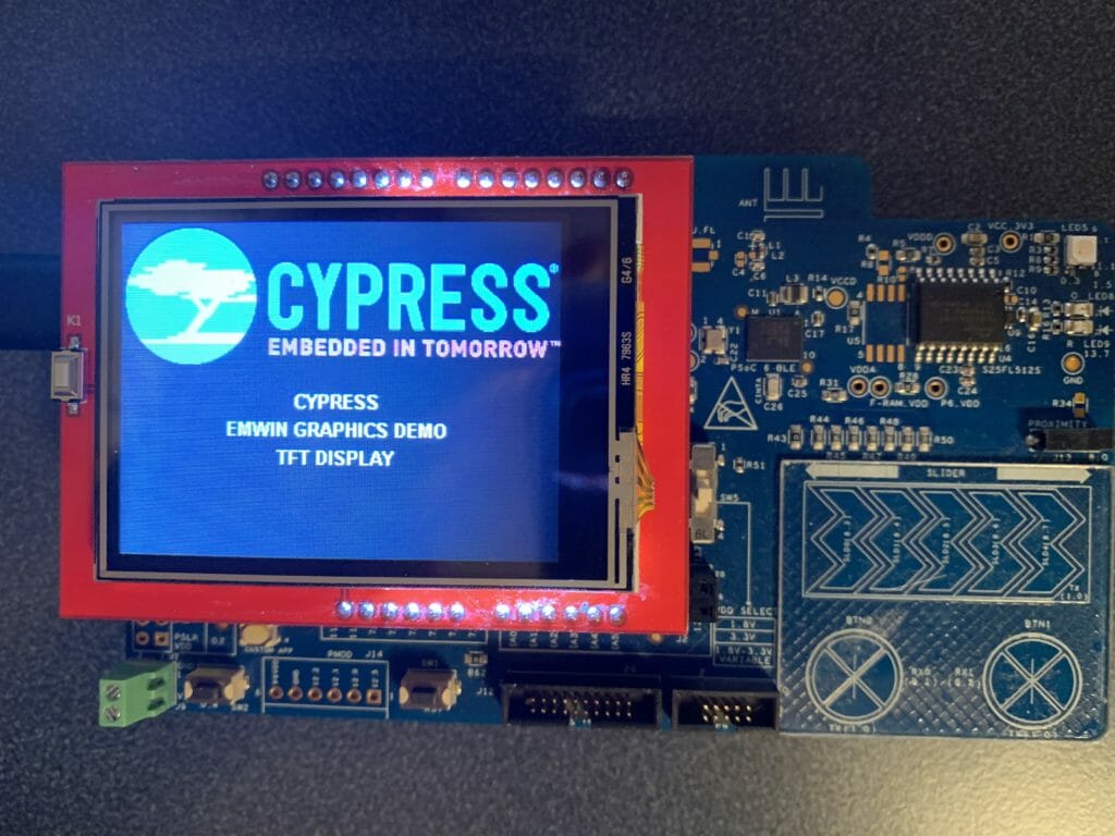
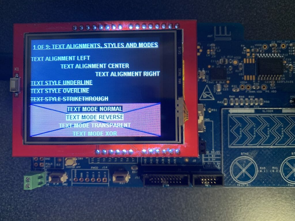
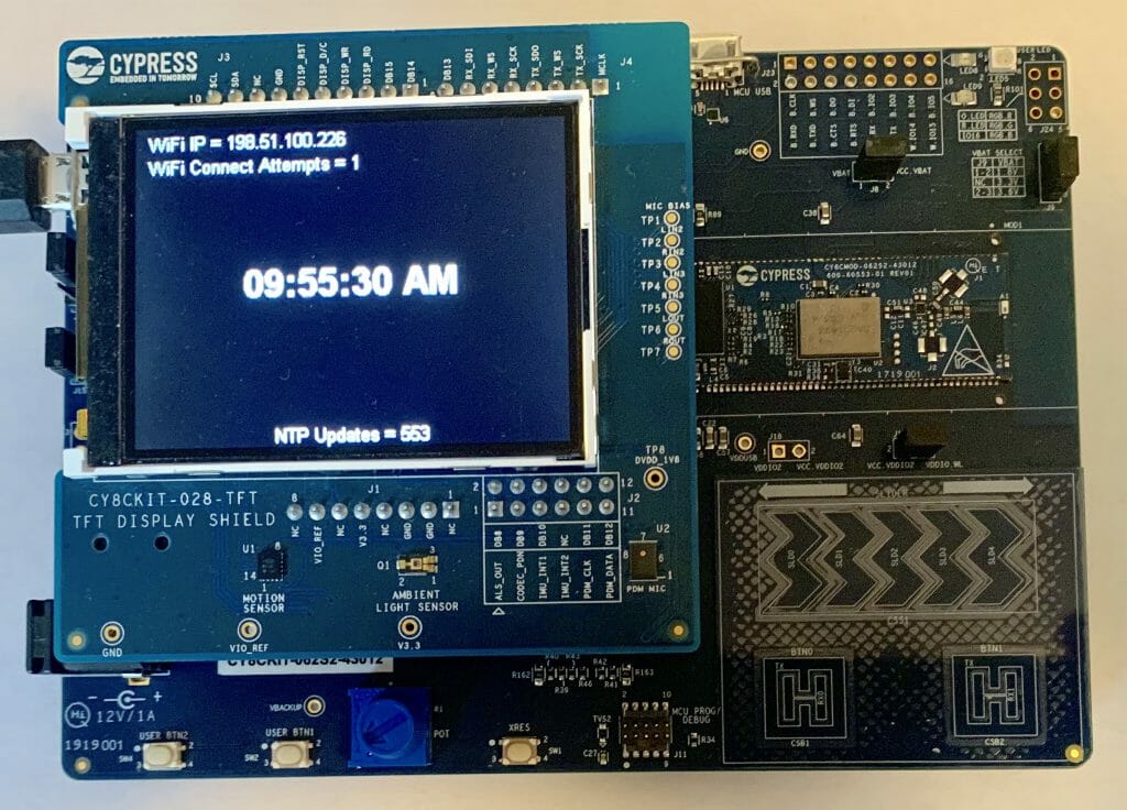
Have you ever wondered about the nature of time?  Given the demographics of my readers I am quite sure that all of you have pondered this topic.  In this article I will solve one of the great mysteries of human kind.  What time is it?  Well that may be a little bit over dramatic 🙂  Actually what I will show you is how to use the CY8CKIT-062S2-43012 development kit to get time from the internet using the Network Time Protocol (NTP), update the PSoC 6 RTC and display it on the CY8CKIT-028-TFT using MBED OS.

Unfortunately I will not show you a beautiful way to convert UTC to Eastern Time because I don’t actually know what that way would be which is very frustrating.  Every way that I know requires me to drag a lot of crap into my PSoC6 which I don’t really want to do.

For this article I will discuss:

  1. MBED OS Project Setup
  2. MBED OS Event Queues
  3. The RTOS Architecture
  4. The Display Function(s)
  5. The NTP Thread
  6. The WiFI/Main Thread
  7. The Whole Program

Project Setup: Create and Configure Project + Add the Libraries

You should start this project by creating a project by running “mbed new NTPDemo” or by using mbed studio to create a new project.  To run this project requires at least mbed-os-5.13.3.  You have two basic choices to get the latest mbed.  For some reason which I don’t totally understand when you run mbed new it gives you a slightly older version of mbed-os.  To get a new version you can either “cd mbed-os ; mbed update mbed-os-5.13.3” or to get the latest “cd mbed-os ; mbed update master”.

In this project I use three libraries, emWin, the IoT Expert ST7789V library (for the display) and the ntp-client library.  To add them run

The emWin library requires that you tell emWin about which version of the library .a to link with.  You can do this by adding this to the mbed_app.json

{
    "target_overrides": {
        "*": {
            "target.components_add": ["EMWIN_OSNTS"]
        }
    }
}

MBED OS Event Queues

For this project I will use one of the cool RTOS mechanisms that is built into MBED OS,  the “EventQueue“.   There is a nice tutorial in the MBED OS documentation.  An EventQueue is a tool for running a function “later” and in a different thread context.  What does that mean?  It means that there is a thread that sits around waiting until you tell it to run a function.  You tell it to run the function by pushing a function pointer into it’s EventQueue.  In other words, an EventQueue is a thread that waits for functions to be pushed into queue.  When the function is pushed into the queue it runs it.

How is this helpful?  There are a several of reasons.

  • If you are in an ISR it allows you to defer execution of something to the main program.
  • It can be used to serialize access to some resource – in my case the display.
  • It allows you to schedule some event to happen regularly

When MBED OS starts it automatically creates two of these event queues one of the queue threads runs at “osPriorityNormal” and can be accessed via mbed_event_queue();  The other event queue runs at “osPriorityHigh” and can be accesed by mbed_highprio_event_queue();  For some reason (which I don’t understand) these queues are documented on a separate page.

The RTOS Architecture

Here is a picture of the architecture of my program.


The Main Thread

The main function which is also the main thread, which then becomes the WiFi Thread

  1. Initializes the GUI
  2. Starts up the Display Event Queue
  3. Turns on the WiFi and attaches a callback (to notify the program of WiFI Status Changes)
  4. Try’s to connect to the WiFi Network
  5. If it fails, it updates the display and try’s again after 2 seconds
  6. Once it is connected it starts up the NTP Server Thread
  7. And then waits for the WiFi semaphore to be set… which only happens if WiFi gets disconnected at which point it goes back to the start of the WiFI connection and try again.
int main()
{
    int wifiConnectionAttempts;
    int ret;

    GUI_Init();
    displayQueue = mbed_event_queue();
    displayQueue->call_every(1000, &updateDisplayTime);

    wifi = WiFiInterface::get_default_instance();
    wifi->attach(&wifiStatusCallback);

   while(1)
   {
       wifiConnectionAttempts = 1;
        do {

            ret = wifi->connect(MBED_CONF_APP_WIFI_SSID, MBED_CONF_APP_WIFI_PASSWORD, NSAPI_SECURITY_WPA_WPA2);
            displayQueue->call(updateDisplayWiFiConnectAttempts,wifiConnectionAttempts);

            if (ret != 0) {
                wifiConnectionAttempts += 1;
                wait(2.0); // If for some reason it doesnt work wait 2s and try again
            }
        } while(ret !=0);

        // If the NTPThread is not running... then start it up
        if(netTimeThreadHandle.get_state() == Thread::Deleted)
            netTimeThreadHandle.start(NTPTimeThread);
 
        WiFiSemaphore.acquire();
   }

Display Event Queue

Display EventQueue is used to run functions which update the display.  By using an EventQueue it ensure that the Display updates happen serially and there are no display resource conflicts.  The four functions are

  1. updateDisplayWiFiStatus
  2. updateDisplayWifiConnectAttempts
  3. updateDisplayNTPCount
  4. updateDisplayTime

I wanted a function which could display the state of the WiFi connection on the screen.  This is a string of text which is generated in the connection status function.  In order to send the message, the connection status function will “malloc” which then requires the updateDisplayWiFiStatus function to free the memory associated with the message.

#define DISP_LEFTMARGIN 10
#define DISP_TOPMARGIN 4
#define DISP_LINESPACE 2
// updateDisplayWiFiStatus
// Used to display the wifi status
void updateDisplayWiFiStatus(char *status)
{
    GUI_SetFont(GUI_FONT_16_1);
    GUI_DispStringAt(status,DISP_LEFTMARGIN, DISP_TOPMARGIN); 
    free(status);  
}

When I started working on this program I had a bug in my connections so I added the ability to tell how many WiFI connections attempts had happened.  I also wondered how many times there might be a disconnect if I ran this program a long time.  The answer is I ran it for two days and it didn’t disconnect a single time.  This function simply takes a number from the caller and displays it on the screen.  Notice that I use snprintf to make sure that I don’t overrun the buffer (which I doubt could happen because I made it 128 bytes).

// updateDisplayWiFiConnectAttempts
// This function displays the number of attempted connections
void updateDisplayWiFiConnectAttempts(int count)
{
    char buffer[128];
    snprintf(buffer,sizeof(buffer),"WiFi Connect Attempts = %d",count); 
    GUI_SetFont(GUI_FONT_16_1);
    GUI_DispStringAt(buffer,DISP_LEFTMARGIN, DISP_TOPMARGIN + (GUI_GetFontSizeY()+DISP_LINESPACE) ); 
}

I was curious how many times the NTP connection would happen.  So I added the ability to display a count.  Notice that I use a static variable to keep track of the number of times this function is called rather than pushing the number as an argument.  Perhaps this is a design flaw?

// updateDisplayNTPCount
// updates the display with the number of time the NTP Server has been called
void updateDisplayNTPCount(void)
{
    static int count=0;
    char buffer[128];
    count = count + 1;
    snprintf(buffer,sizeof(buffer),"NTP Updates = %d\n",count);
    GUI_SetFont(GUI_FONT_16_1);
    GUI_DispStringHCenterAt(buffer,LCD_GetXSize()/2,LCD_GetYSize() - GUI_GetFontSizeY()); // near the bottom
}

The main display function is the seconds which is displayed in the middle of the screen.  I get the time from the RTC in the PSoC and is set by the NTP Server.  Notice my rather serious hack to handle the Eastern time difference to UTC… which unfortunately only works in the Summer.

// updateDisplayTime
// This function updates the time on the screen
void updateDisplayTime()
{
  time_t rawtime;
  struct tm * timeinfo;
  char buffer [128];

  time (&rawtime);
  rawtime = rawtime - (4*60*60); // UTC - 4hours ... serious hack which only works in summer

  timeinfo = localtime (&rawtime);
  strftime (buffer,sizeof(buffer),"%r",timeinfo);
  GUI_SetFont(GUI_FONT_32B_1);
  GUI_DispStringHCenterAt(buffer,LCD_GetXSize()/2,LCD_GetYSize()/2 - GUI_GetFontSizeY()/2);
}

NTP Time Thread

The Network Time Protocol was invented in 1981 by Dr. David Mills for use in getting Internet connected computers to have the right time.  Since then it has been expanded a bunch of times to include Cellular, GPS and other networks.  The scheme includes methods for dealing with propogation delay etc.  However, for our purposes we will just ask one of the NIST computers, what time is it?

The way it works is that you setup a structure with 48 bytes in it.  Then you open a UDP connection to an NTP server (which NIST runs for you) then it will fill out the same structure with some time data and send it back to you.  Here is the packet:

typedef struct
{

  uint8_t li_vn_mode;      // Eight bits. li, vn, and mode.
                           // li.   Two bits.   Leap indicator.
                           // vn.   Three bits. Version number of the protocol.
                           // mode. Three bits. Client will pick mode 3 for client.

  uint8_t stratum;         // Eight bits. Stratum level of the local clock.
  uint8_t poll;            // Eight bits. Maximum interval between successive messages.
  uint8_t precision;       // Eight bits. Precision of the local clock.

  uint32_t rootDelay;      // 32 bits. Total round trip delay time.
  uint32_t rootDispersion; // 32 bits. Max error aloud from primary clock source.
  uint32_t refId;          // 32 bits. Reference clock identifier.

  uint32_t refTm_s;        // 32 bits. Reference time-stamp seconds.
  uint32_t refTm_f;        // 32 bits. Reference time-stamp fraction of a second.

  uint32_t origTm_s;       // 32 bits. Originate time-stamp seconds.
  uint32_t origTm_f;       // 32 bits. Originate time-stamp fraction of a second.

  uint32_t rxTm_s;         // 32 bits. Received time-stamp seconds.
  uint32_t rxTm_f;         // 32 bits. Received time-stamp fraction of a second.

  uint32_t txTm_s;         // 32 bits and the most important field the client cares about. Transmit time-stamp seconds.
  uint32_t txTm_f;         // 32 bits. Transmit time-stamp fraction of a second.

} __PACKED ntp_packet_t;              // Total: 384 bits or 48 bytes.

The code to send the packet is really simple.  The only trick is that when you send data on the network you almost always use big endian, so you need to use the function nthol to convert.

void NTPClient::set_server(char* server, int port) {
    nist_server_address = server;
    nist_server_port = port;
}

time_t NTPClient::get_timestamp(int timeout) {
    const time_t TIME1970 = (time_t)2208988800UL;
    int ntp_send_values[12] = {0};
    int ntp_recv_values[12] = {0};

    SocketAddress nist;

    if (iface) {
        int ret_gethostbyname = iface->gethostbyname(nist_server_address, &nist);

        if (ret_gethostbyname < 0) {
            // Network error on DNS lookup
            return ret_gethostbyname;
        }

        nist.set_port(nist_server_port);

        memset(ntp_send_values, 0x00, sizeof(ntp_send_values));
        ntp_send_values[0] = '\x1b';

        memset(ntp_recv_values, 0x00, sizeof(ntp_recv_values));

        UDPSocket sock;
        sock.open(iface);
        sock.set_timeout(timeout);

        sock.sendto(nist, (void*)ntp_send_values, sizeof(ntp_send_values));

        SocketAddress source;
        const int n = sock.recvfrom(&source, (void*)ntp_recv_values, sizeof(ntp_recv_values));

        if (n > 10) {
            return ntohl(ntp_recv_values[10]) - TIME1970;

The times in the structure are represented with two 32-bit numbers

  • # of seconds since 1/1/1900 (notice this is not 1970)
  • # of fractional seconds in 1/2^32 chunks (that ain’t a whole lotta time)

The four numbers are

  • Reference Time – when you last sent a packet
  • Origin Time – when you sent the packet (from your clock)
  • Receive Time – when the NTP server received your packet
  • Transmit Time – when your NTP server sent the packet back to you

You know when you send the packet – called T1.  You know when you received the packet – called T4.  You know when the other side received your packet – called T2 and you know when the other side sent the packet called T3.  With this information you can calculate the network delay, stability of the clocks etc.  However, the simplest thing to do is to take the transit time, which is in UTC, and set your clock assuming 0 delay.

In MBEDOS to set the RTC clock in the PSoC you call the function with the number of seconds since 1/1/1970.  Don’t forget that the time that comes back from NTP is in seconds since 1/1/1900.

                set_time(timestamp);

Given that the PSoC 6 RTC counts in seconds you can just ignore the partial seconds.

WiFi Semaphore

At the top of main I registered to WiFi that I want a callback when the state of the WiFi changes.

    wifi->attach(&wifiStatusCallback);

This function does two things.

  • Updates the screen as the state goes from unconnected to connected
  • Unlocks a semaphore to tell the main thread to reconnect.
// wifiStatusCallback
// Changes the display when the wifi status is changed
void wifiStatusCallback(nsapi_event_t status, intptr_t param)
{
    const int buffSize=40;
    char *statusText;
    statusText = (char *)malloc(buffSize);

    switch(param) {
        case NSAPI_STATUS_LOCAL_UP:
            snprintf(statusText,buffSize,"WiFi IP = %s",wifi->get_ip_address());
            break;
        case NSAPI_STATUS_GLOBAL_UP:
            snprintf(statusText,buffSize,"WiFi IP = %s",wifi->get_ip_address());
            break;
        case NSAPI_STATUS_DISCONNECTED:
            WiFiSemaphore.release();
            snprintf(statusText,buffSize,"WiFi Disconnected");
            break;
        case NSAPI_STATUS_CONNECTING:
            snprintf(statusText,buffSize,"WiFi Connecting");
            break;
        default:
            snprintf(statusText,buffSize,"Not Supported");
            break;
    }
    displayQueue->call(updateDisplayWiFiStatus,statusText);
}

The Whole Program

Here is the whole program.

#include "mbed.h"
#include "GUI.h"
#include "mbed_events.h"
#include "ntp-client/NTPClient.h"

Thread netTimeThreadHandle;

WiFiInterface *wifi;
EventQueue *displayQueue;
Semaphore WiFiSemaphore;

/******************************************************************************************
*
* Display Functions
*
********************************************************************************************/

#define DISP_LEFTMARGIN 10
#define DISP_TOPMARGIN 4
#define DISP_LINESPACE 2
// updateDisplayWiFiStatus
// Used to display the wifi status
void updateDisplayWiFiStatus(char *status)
{
    GUI_SetFont(GUI_FONT_16_1);
    GUI_DispStringAt(status,DISP_LEFTMARGIN, DISP_TOPMARGIN); 
    free(status);  
}

// updateDisplayWiFiConnectAttempts
// This function displays the number of attempted connections
void updateDisplayWiFiConnectAttempts(int count)
{
    char buffer[128];
    snprintf(buffer,sizeof(buffer),"WiFi Connect Attempts = %d",count); 
    GUI_SetFont(GUI_FONT_16_1);
    GUI_DispStringAt(buffer,DISP_LEFTMARGIN, DISP_TOPMARGIN + (GUI_GetFontSizeY()+DISP_LINESPACE) ); 
}

// updateDisplayNTPCount
// updates the display with the number of time the NTP Server has been called
void updateDisplayNTPCount(void)
{
    static int count=0;
    char buffer[128];
    count = count + 1;
    snprintf(buffer,sizeof(buffer),"NTP Updates = %d\n",count);
    GUI_SetFont(GUI_FONT_16_1);
    GUI_DispStringHCenterAt(buffer,LCD_GetXSize()/2,LCD_GetYSize() - GUI_GetFontSizeY()); // near the bottom
}

// updateDisplayTime
// This function updates the time on the screen
void updateDisplayTime()
{
  time_t rawtime;
  struct tm * timeinfo;
  char buffer [128];

  time (&rawtime);
  rawtime = rawtime - (4*60*60); // UTC - 4hours ... serious hack which only works in summer

  timeinfo = localtime (&rawtime);
  strftime (buffer,sizeof(buffer),"%r",timeinfo);
  GUI_SetFont(GUI_FONT_32B_1);
  GUI_DispStringHCenterAt(buffer,LCD_GetXSize()/2,LCD_GetYSize()/2 - GUI_GetFontSizeY()/2);
}

/******************************************************************************************
* NTPTimeThread
* This thread calls the NTP Timeserver to get the UTC time
* It then updates the time in the RTC
* And it updates the display by adding an event to the display queue
********************************************************************************************/
void NTPTimeThread()
{
    NTPClient ntpclient(wifi);

    while(1)
    {
        if(wifi->get_connection_status() == NSAPI_STATUS_GLOBAL_UP)
        {
            time_t timestamp = ntpclient.get_timestamp();
            if (timestamp < 0) {
                // probably need to do something different here
            } 
            else 
            {
                set_time(timestamp);
                displayQueue->call(updateDisplayNTPCount);
            }
        }
        wait(60.0*5); // Goto the NTP server every 5 minutes
    }
}

/******************************************************************************************
*
* Main & WiFi Thread
*
********************************************************************************************/

// wifiStatusCallback
// Changes the display when the wifi status is changed
void wifiStatusCallback(nsapi_event_t status, intptr_t param)
{
    const int buffSize=40;
    char *statusText;
    statusText = (char *)malloc(buffSize);

    switch(param) {
        case NSAPI_STATUS_LOCAL_UP:
            snprintf(statusText,buffSize,"WiFi IP = %s",wifi->get_ip_address());
            break;
        case NSAPI_STATUS_GLOBAL_UP:
            snprintf(statusText,buffSize,"WiFi IP = %s",wifi->get_ip_address());
            break;
        case NSAPI_STATUS_DISCONNECTED:
            WiFiSemaphore.release();
            snprintf(statusText,buffSize,"WiFi Disconnected");
            break;
        case NSAPI_STATUS_CONNECTING:
            snprintf(statusText,buffSize,"WiFi Connecting");
            break;
        default:
            snprintf(statusText,buffSize,"Not Supported");
            break;
    }
    displayQueue->call(updateDisplayWiFiStatus,statusText);
}


int main()
{
    int wifiConnectionAttempts;
    int ret;

    GUI_Init();
    displayQueue = mbed_event_queue();
    displayQueue->call_every(1000, &updateDisplayTime);

    wifi = WiFiInterface::get_default_instance();
    wifi->attach(&wifiStatusCallback);

   while(1)
   {
       wifiConnectionAttempts = 1;
        do {

            ret = wifi->connect(MBED_CONF_APP_WIFI_SSID, MBED_CONF_APP_WIFI_PASSWORD, NSAPI_SECURITY_WPA_WPA2);
            displayQueue->call(updateDisplayWiFiConnectAttempts,wifiConnectionAttempts);

            if (ret != 0) {
                wifiConnectionAttempts += 1;
                wait(2.0); // If for some reason it doesnt work wait 2s and try again
            }
        } while(ret !=0);

        // If the NTPThread is not running... then start it up
        if(netTimeThreadHandle.get_state() == Thread::Deleted)
            netTimeThreadHandle.start(NTPTimeThread);
 
        WiFiSemaphore.acquire();
   }
}
 

MBEDOS Libraries & emWin Configuration Files

Summary

I have written a fair amount about Graphics Displays, using the Segger emWin graphics library and MBED OS.  I have found it irritating to do all of the configuration stuff required to get these kinds of projects going.  I inevitably go back, look at my old articles, find the github repository of my example projects etc.  This week I wanted to write some programs for the new CY8CKIT-062S2-43012 development kit so I thought that I would try all of the Cypress displays using that development kit.  Rather than starting with example projects, this time I decided to build configurable mbedos libraries. In this article I will show you how to build configurable mbed os libraries which will allow you to use the emWin Graphics Library with all of the Cypress display shields.

In this article I will walk you through:

  • The CY8CKIT-032 & SSD1306 Display Driver & emWin
  • MBED OS Libraries
  • MBED OS Configuration
  • Configuration Overrides
  • The SSD1306 emWin Configuration
  • Using the SSD1306 Configuration Library
  • emWin Configuration Libraries

The CY8CKIT-032 & SSD1306 Display Driver & emWin

The CY8CKIT-032 has a little 0.96″ OLED display that is attached to the Salomon Systech SSD1306 Display Driver.  I have written quite a bit about this little screen as it is cheap and fairly easy to use.  It became even easier when we released the Segger emWin SPAGE display driver.  And with my new library it should be trivial to use and configure for your setup.

You can read in detail about the functionality here but in short:

  • The display driver chip is attached to the PSoC via I2C
  • You need to provide the Segger emWin driver
    • GUIConfig.h/cpp – Segger GUI configuration
    • LCDConf.h/cpp – Setup files for the LCD
    • GUI_X_Mbed.cpp – RTOS control functions for delays etc.
    • ssd1306.h/c – physical interface to the SSD1306 controller
  • You need to initialize the PSoC I2C before talking to the display
  • You need to initialize the display driver chip before drawing on the screen

In general all of this configuration will be the same from project to project to project.  However, you may very will find that you have the display connected to a different set of pins.  I suppose that would put all of these files into some directory.  Then you could copy that directory into your project every time.  Which would leave you with modifying the configuration to meet your specific board connection.  The problem with that is you have now deeply intertwined your project with those files.

MBED OS has given us a really cool alternative.  Specifically the Library and configuration systems.

MBED OS Libraries

An MBED OS library is simply a git repository.  Just a directory of source files.  When you run the command “mbed add repository” it does two basic things

  1. It does a “git clone” to make a copy of the repository inside of your project.
  2. It creates a file with the repository name.lib which contains the URL to the version of the repository

Here is a an MBED add of my graphics configuration library for the SSD1306

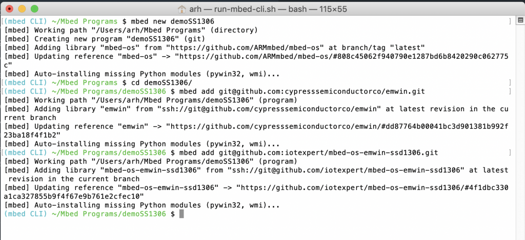
(mbed CLI) ~/Mbed Programs/test032 $ mbed add git@github.com:iotexpert/mbed-os-emwin-ssd1306.git
[mbed] Working path "/Users/arh/Mbed Programs/test032" (program)
[mbed] Adding library "mbed-os-emwin-ssd1306" from "ssh://git@github.com/iotexpert/mbed-os-emwin-ssd1306" at latest revision in the current branch
[mbed] Updating reference "mbed-os-emwin-ssd1306" -> "https://github.com/iotexpert/mbed-os-emwin-ssd1306/#7986006c17bd572da317257640f35ec3b232414e"
(mbed CLI) ~/Mbed Programs/test032 $ ls mbed-os-emwin-ssd1306
GUIConf.cpp    GUI_X_Mbed.cpp LCDConf.h      mbed_lib.json  ssd1306.h
GUIConf.h      LCDConf.cpp    README.md      ssd1306.cpp
(mbed CLI) ~/Mbed Programs/test032 $ more mbed-os-emwin-ssd1306.lib 
https://github.com/iotexpert/mbed-os-emwin-ssd1306/#7986006c17bd572da317257640f35ec3b232414e
(mbed CLI) ~/Mbed Programs/test032 $ 

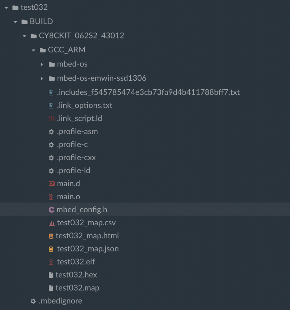
Notice that when I “ls’d” the directory that all of file required to confiugure emWin for the SSD1306 became part of my project.  And the file mbed-os-emwin-ssd1306.lib was created with the URL of the github repository.

https://github.com/iotexpert/mbed-os-emwin-ssd1306/#7986006c17bd572da317257640f35ec3b232414e

When you run “mbed compile” the build system just searches that directory for cpp and h files turns them into .0’s and add them to the the BUILD directory.  However, before it compiles it run the configuration system.

MBED OS Configuration System

The configuration system takes the file “mbed_lib.json” parses it and turns it into a C-header file called mbed_config.h.  The format of this file is

  • The name of the component – in this case “SSD1306_OLED”
  • The parameters of the component SDA, SCL, I2CADDRESS and I2CFREQ
{
    "name" : "SSD1306_OLED",
    "config": {
        "SDA":"P6_1",
        "SCL":"P6_0",
        "I2CADDRESS":"0x78",
        "I2CFREQ":"400000"
    }
}

This header file is then placed into the BUILD directory of your project and is included as part of #include “mbed.h”

If you open mbed_config.h you will find that it creates #defines of the component parameters

#define MBED_CONF_SSD1306_OLED_I2CADDRESS                                     0x78                                                                                             // set by library:SSD1306_OLED
#define MBED_CONF_SSD1306_OLED_I2CFREQ                                        400000                                                                                           // set by library:SSD1306_OLED
#define MBED_CONF_SSD1306_OLED_SCL                                            P6_0                                                                                             // set by library:SSD1306_OLED
#define MBED_CONF_SSD1306_OLED_SDA                                            P6_1

This is really nice because I can then reference those #defines in my source code.

Configuration Overrides

When you are building the library you can create an arbitrary number of these parameters which are then applied to all of the uses of that library.  Or if there is some reason why one target is different you can specify the parameters for that specific target by changing the mbed_lib.json.  For instance if the CY8CKIT_062S2_43012 need a 100K I2C frequency instead of 400K (it doesn’t), you could do this:

{
    "name" : "SSD1306_OLED",
    "config": {
        "SDA":"P6_1",
        "SCL":"P6_0",
        "I2CADDRESS":"0x78",
        "I2CFREQ":"400000"
    },
    "target_overrides" : {
        "CY8CKIT_062S2_43012" : {
            "I2CFREQ":"100000"
        }
    }
}

The application developer is also allowed to over-ride the parameter by providing the target overrides in the MBED OS file “mbed_app.json”.  Notice that the way you specify the parameter name is different in this file than the mbed_lib.json.  In this case you give it the name of the library.parametername.  Here is an example setting the I2CFrequency to 100K

{
	"target_overrides": {
        "*": {
            "target.components_add": ["EMWIN_OSNTS"]
        },
        "CY8CKIT_062S2_43012" : {
            "SSD1306_OLED.I2CFREQ": "1000000"
        }
	}
}

Which would result in a change to the generated #define in mbed_config.h

#define MBED_CONF_SSD1306_OLED_I2CFREQ                                        1000000

Notice that you can specify a “*” to match all of the targets, or you can specify the exact target.

The SSD1306 emWin Configuration

I use the configuration system to generate #defines for the

  • SCL/SDA Pin Numbers
  • I2C Address
  • I2C Frequency

Which lets my use those #defines in ssd1306.cpp

I2C Display_I2C(MBED_CONF_SSD1306_OLED_SDA, MBED_CONF_SSD1306_OLED_SCL);

And

void ssd1306_Init(void) 
{
    Display_I2C.frequency(MBED_CONF_SSD1306_OLED_I2CFREQ);
}

Using the SSD1306 Configuration Library

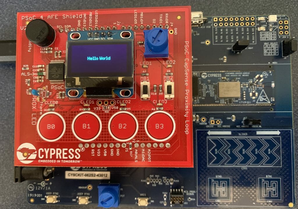
Lets make an example project that uses the CY8CKIT_062S2_43012 and the CY8CKIT032 using the Segger graphics library and my configuration library.

Start by make a new project, adding the emWin library and the configuration library.  It should look something like this

Now edit the mbed_app.json to add the emWin library

{
	"target_overrides": {
        "*": {
            "target.components_add": ["EMWIN_OSNTS"]
        }
	}
}

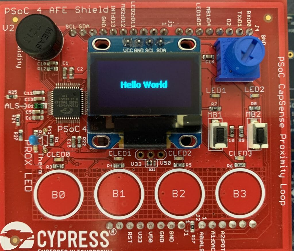
Create the main.cpp which simply initializes the display and displays “hello world”

#include "mbed.h"
#include "GUI.h"

int main()
{
  GUI_Init();
  GUI_SetColor(GUI_WHITE);
  GUI_SetBkColor(GUI_BLACK);
  GUI_SetFont(GUI_FONT_13B_1);
  GUI_SetTextAlign(GUI_TA_CENTER);
  GUI_DispStringAt("Hello World", GUI_GetScreenSizeX()/2,GUI_GetScreenSizeY()/2 - GUI_GetFontSizeY()/2);
}

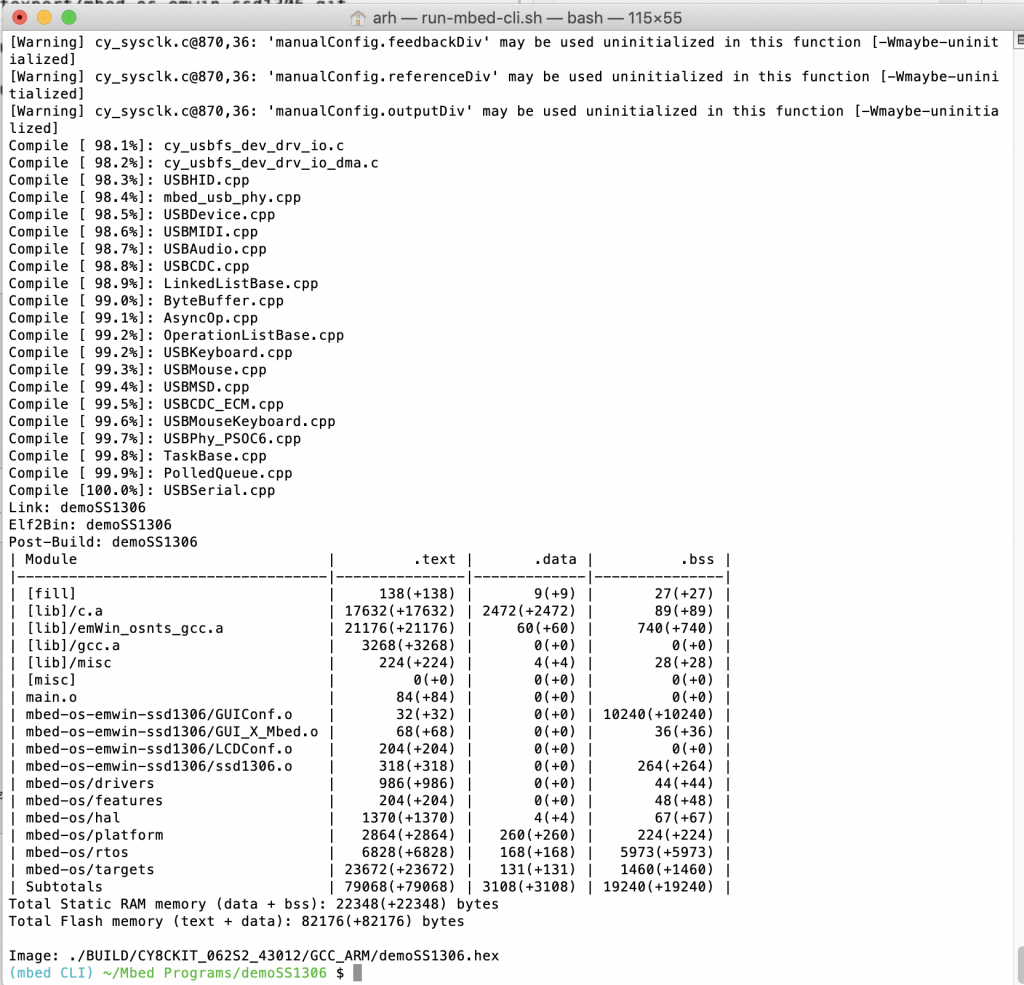
When you compile it with

  • mbed compile -t GCC_ARM -m CY8CKIT_062S2_43012 -f

You should get something like this:

And your screen should look like this (notice I made the font bigger than the original screen shot)

emWin Configuration Libraries

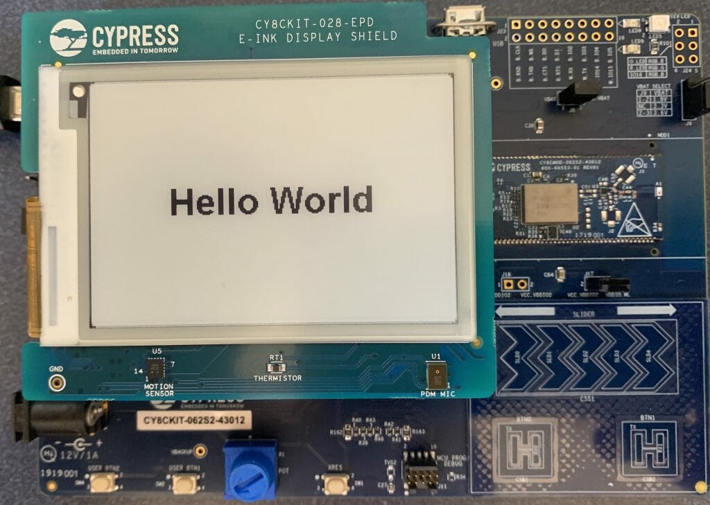
Finally I created libraries for all of the Cypress displays.  You can use these to make your project easier to get going.


Debugging SSD1306 Display Problems

Summary

This article explains in detail how to use and debug SSD1306 displays.  In this article, I use the Segger emWin library and MBEDOS, but for all practical purposes this discussion applies to all other interfaces to the board including Arduino, Raspberry Pi, Adafruit, etc.  I will say from the outset that I spent far far too much time digging into the inner workings of an 11 year old graphics driver.  Oh well, hopefully someone will get some benefit.

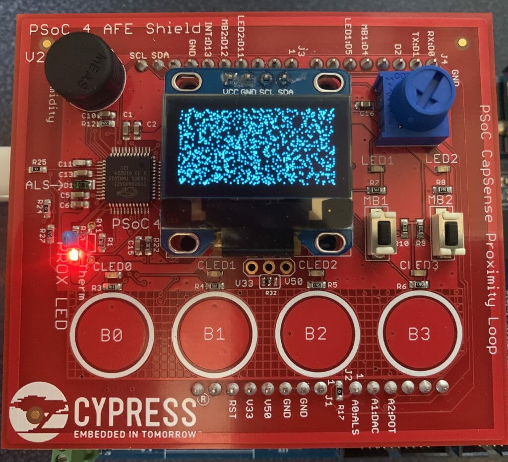
A year ago (or so) I designed a user interface board called the CY8CKIT-032 to go with my Cypress WICED WiFi book and class.  This board uses a PSoC 4 Analog co-processor which can do a bunch of cool stuff.  I have a series of articles planned about that board, but that will be for another day.  One of the things that I did was put a 0.96″ I2C OLED Display based on a SSD1306 driver on the board.  These displays are widely available from Alibaba and eBay for <$2.  I think that the displays are being used in inexpensive cells phones in China so there are tons of them and they are CHEAP!  The bad news is that if you google “ssd1306 problems” you will find an absolute rogues gallery of unpleasantness.  It seems that tons of people struggle to get these things working.

This whole thing started last week as Cypress released and update to our MBED OS implementation.  This update included releasing a complete set of the Segger emWin drivers.  I had been wanting to step up to a more robust graphics library than the Adafruit library that I used in this article.  I was pleased to see that our release included the emWin SPAGE driver which knows how to talk to a bunch of different page based displays including the SSD1306.

But, as always, I had to wrestle with the display a little bit before I got everything working.  This time I wrote down what I did/learned.  So, for this article I will describe

  • The SSD1306 Electrical Interface
  • The SSD1306 Software Interface
  • The SSD1306 Driver Registers
  • The SSD1306 Graphics Data RAM
  • Reading from the Frame Buffer
  • My Initialization Sequence
  • Some Other Initialization Sequences
  • A Bunch of Screen Problems & How To Fix

The Electrical Interface

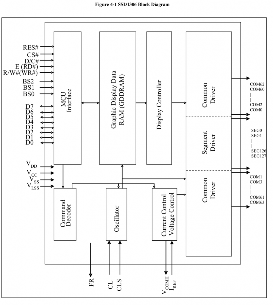
There is not a lot to know about the electrical interface.  The data sheet specifies that the device can use I2C, SPI, 6800 and 8080.  I have not seen either the 6800 or 8080 interface put onto any of these OLED displays.  Like all driver chips, the SSD1306 has an absolute boatload of pins, in fact, 281.  The chip is long and skinny and was made to be mounted either on the display under the glass or on the flex connector.  Of the 281 pins, 128+64=196 are connected to the segments and commons in the display.  The rest of the pins are either capacitors, no-connects, power/ground or data signals.  The data signals are

  • D0-D7 either parallel data for 8080/6800 or SDA/SCL for I2C or MOSI/MISO for SPI
  • E – enable signal for 6800 or RD for 8080
  • R/W# – Read Write for 6800/8080
  • CS – Chip Select for SPI, 8080, 6800
  • D/C# – Data or Command for SPI, 6800, 8080 or Slave Address Select for I2C
  • Reset – Chip reset

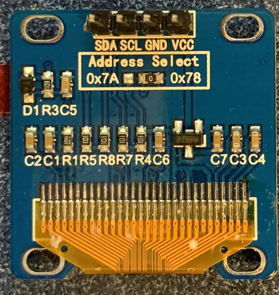
For the I2C configurations it is common to tie the reset pin High and not bring the pin to a connector.  The SA0 is also typically connected via a 0-ohm resistor to either 0 or 1 which configures the device to have the 7-bit address 0x3C or 0x3D or 8-bit 0x78 or 0x7A.  Here is a picture of the back of one of my boards where you can see the 0ohm resistor.

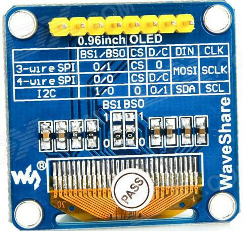
Sometimes all of the data pins are available on the back of the board.  This lets you move/add/change the 0-ohm resistors to configure the mode of the chip.

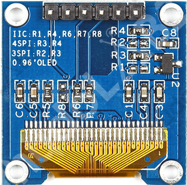
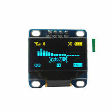
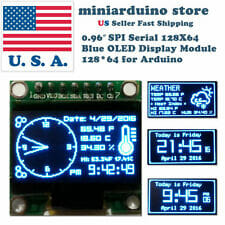
One thing you should be careful about is the I2C connections.  I looked around on eBay and Alibaba to find a few pictures of the I2C displays.  You should notice that all three of these displays are I2C, but all three of them have a different position and ORDER of VCC/GND/SCL/SDL  When we ordered displays from China to go onto the CY8CKIT-032 we found displays in the same BATCH that had different orders of the VCC/GND.


Here is a SPI version that has reset and data/command pin brought out.


The Software Interface

There are two parts to the software interface.

The first part is the command interface.  Inside of the chip there are a bunch of logic circuits which which configure the charge pumps, sequence COMs and SEGs, charge and discharge capacitors etc.  All of these things are configurable to allow for different configurations of screens e.g. different x-y sizes, configuration of what wires are connected to what places on the glass etc.  Before you can get the display to work correctly you must initialize all of these values by sending commands.  All the commands are 1-byte followed by 0 or more command parameters.

The second part is the data interface.  Inside of the SSD1306 chip there is a Graphics Display DRAM – GDDRAM which has 1 bit for every pixel on the screen. The state machine inside of the chip called the Display Controller will loop through the bits one by one and display them on the correct place on the screen.  This means that your MCU does not need to do anything to keep the display up to date.  When you want a pixel lit up on the screen you just need to write the correct location in the GDDRAM.

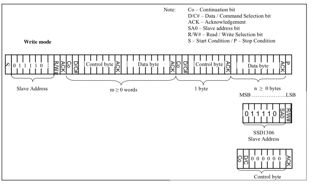
For the rest of this article I will focus on the serial interface, I2C.  How do you send commands and data?  Simple.  When you start a transaction you send a control byte which tells the controller what to expect next.  There are four legal control bytes.

  • 0b10000000 = 0x80 = multiple commands
  • 0b00000000 = 0x00 = one command
  • 0b11000000 = 0xC0 = multiple data
  • 0b01000000 = 0x40 = one data byte

Here is the picture from the datasheet (which I don’t find particularly illuminating) but it does describe the control byte.

To send commands you write to the I2C bus with a control byte, then you send the command, then you send the optional parameters.  If you want to send multiple commands you send the control byte 0x80, the command + parameters as many as you need.

The SSD1306 Driver Registers

In order for the driver chip to drive the screen you need to configure:

  1. How the driver is electrically connected to the OLED Screen
  2. What are the electrical parameters of the screen
  3. What are the electrical parameters of the system
  4. How you want to address the frame buffer
  5. The automatic scroll configuration settings
  6. The pixel data for the frame buffer, though it will happily display noise.

If you bought this screen from eBay, Adafruit, Alibaba etc. then you will get no say in 1-3, the electrical parameters of the system.  Your screen will come prewired with all of the capacitors, OLED etc already attached to your driver commons and segments.  If you didn’t buy the screen prepackaged, then it is highly unlikely you are reading this article.  What this means is that you need to know the initializing sequence required to get the screen to work properly, then you just send the sequence down the wire from your MCU to the screen.  From looking around on the internet, it appears to me that there in only one parameter that is different in any of the screens that I could find.  Specifically the number of lines on the screen – either 32 or 64.  Which means that all of these initialization implementations should really on have one difference register 0xA8 should be set to either n-1 aka 31 or 63

The other difference that you will see between different implementations is the memory address mode.  In other words, how do you want to write data into the frame buffer from the MCU.  Many of the open source graphics libraries use “Horizontal” mode.  The Segger emWin library that I am using uses “Page” mode.  More on this later.

When you look in the data sheet, unfortunately they mix and match the order of the information.  However, from the data sheet, the categories are:

  1. Fundamental Commands
  2. Scrolling Commands
  3. Address Setting Commands
  4. Hardware Configuration
  5. Timing and Driving Scheme
  6. Charge Pump

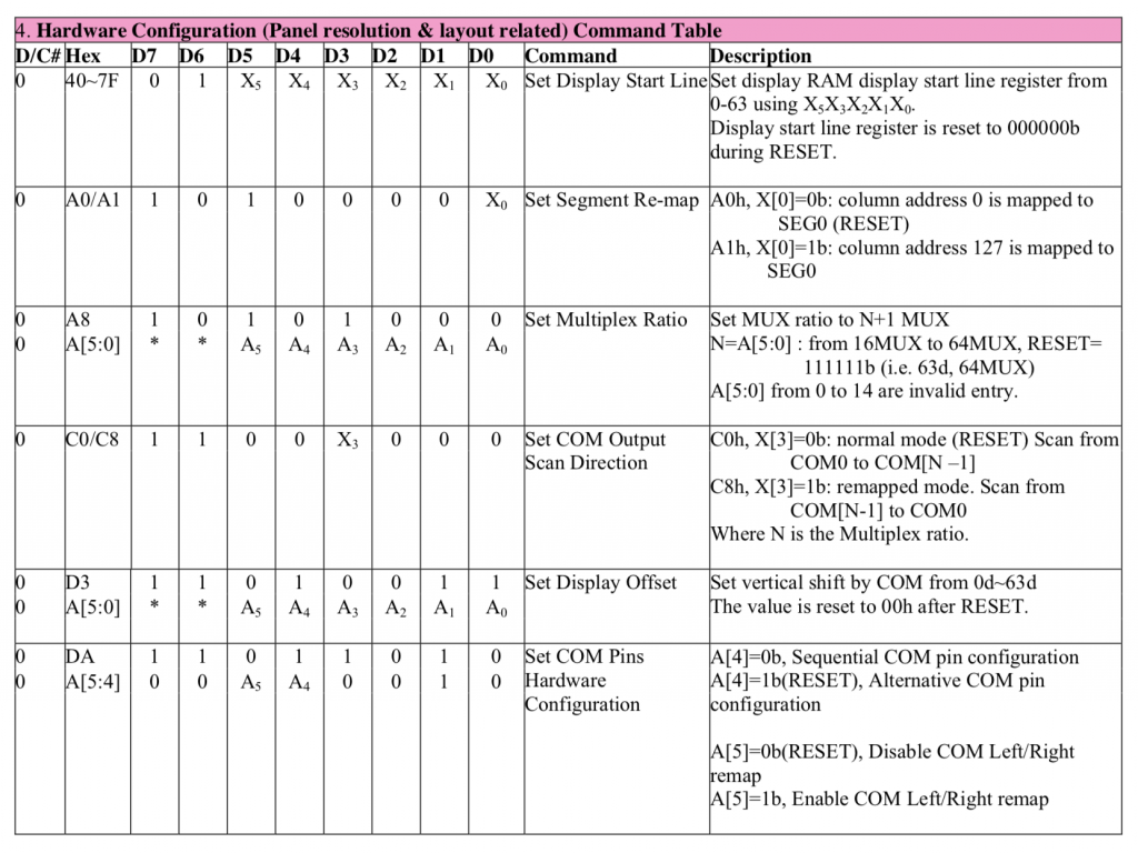
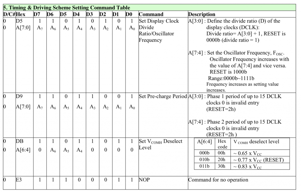
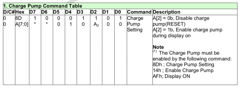
I won’t put screen shots of the whole data sheet into this article, but I will show the command table and make a few clarifications on the text.  Or at least I will clarify places where I got confused.

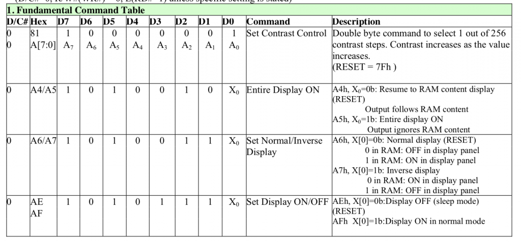
As to the fundamental commands.  I tried a bunch of different contrast settings on my screens and could not tell the difference between them.  I tried from 0x10 to 0xFF and they all looked the same to me.  The best course of action is to use the default 0x7F.  I don’t really know why there is a command 0xA5 “Entire Display ON ignore RAM”.  The data sheet says “A5h command forces the entire display to be “ON”, regardless of the contents of the display data RAM”.  I can’t think of a single use case for this.  I suppose that if you issue 0xAE the screen will be all black… and if you issue 0xA5 the screen will be all white?  But why?

And my definitions in the C driver file:

////////////////////////////////////////////////////////////////////////
// Fundamental Command Table Page 28
////////////////////////////////////////////////////////////////////////
#define OLED_SETCONTRAST                              0x81
// 0x81 + 0-0xFF Contrast ... reset = 0x7F

// A4/A5 commands to resume displaying data
// A4 = Resume to RAM content display
// A5 = Ignore RAM content (but why?)
#define OLED_DISPLAYALLONRESUME                       0xA4
#define OLED_DISPLAYALLONIGNORE                       0xA5

// 0xA6/A7 Normal 1=white 0=black Inverse 0=white  1=black
#define OLED_DISPLAYNORMAL                            0xA6
#define OLED_DISPLAYINVERT                            0xA7

// 0xAE/AF are a pair to turn screen off/on
#define OLED_DISPLAYOFF                               0xAE
#define OLED_DISPLAYON                                0xAF

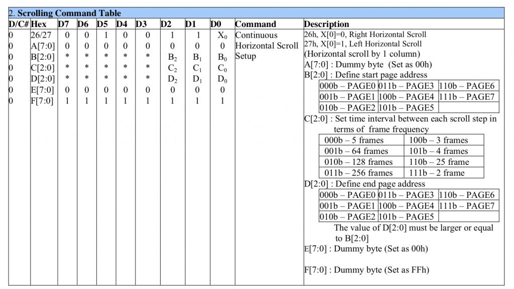
In the next section of the command table are the “Scrolling” commands.  It appears that this graphics chip was setup to display text that is 8-pixels high.  The scrolling commands will let you move the screen up/down and left/right to scroll automatically without having to update the the frame buffer.  In other words it can efficiently scroll the screen without a bunch of load on your MCU CPU or on the data bus between them.  The Adafruit graphics library provides the scrolling commands.  However, I am not using them with the Segger Library.

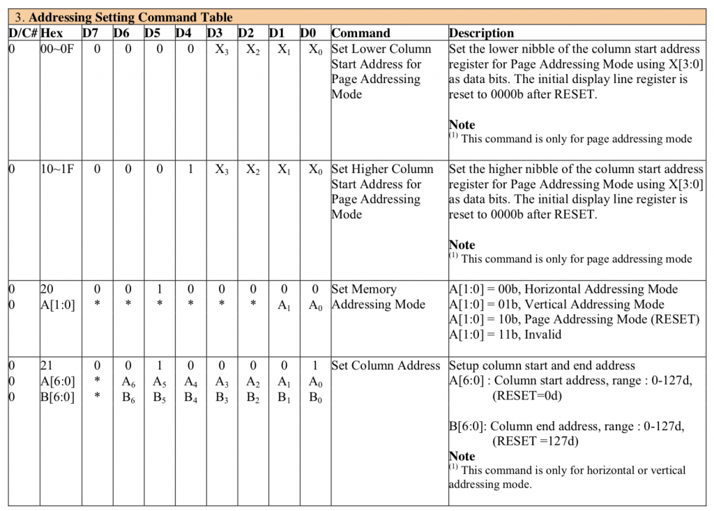
The next section has the commands to configure how your MCU writes data into the Graphics RAM aka the frame buffer. These commands fall into two categories.  First the address mode.  The address modes help you efficiently write the GDDRAM.  When you send data to the frame buffer you really don’t want to send

  • address, pixel, address, pixel, …

What you really would like to do is send

  • Address, pixel, pixel, pixel … (and have the address be automatically incremented

At first blush you might think… why do I need a mode?  Well there are some people who want the x address incremented… there are some people who want the y-address incremented and there are some people who want to have page address access.  And what do you do when you get to the end of a line? or a column or a page? and what does the end mean?

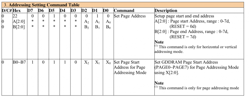
The second set of commands in this table are the commands to set the starting address before you write data.


////////////////////////////////////////////////////////////////////////
// Address Setting Command Table
////////////////////////////////////////////////////////////////////////

// 00-0F - set lower nibble of page address
// 10-1F - set upper niddle of page address

#define OLED_SETMEMORYMODE                            0x20
#define OLED_SETMEMORYMODE_HORIZONTAL                 0x00
#define OLED_SETMEMORYMODE_VERTICAL                   0x01
#define OLED_SETMEMORYMODE_PAGE                       0x02

// 0x20 + 00 = horizontal, 01 = vertical 2= page >=3=illegal

// Only used for horizonal and vertical address modes
#define OLED_SETCOLUMNADDR                            0x21
// 2 byte Parameter
// 0-127 column start address 
// 0-127 column end address

#define OLED_SETPAGEADDR                              0x22
// 2 byte parameter
// 0-7 page start address
// 0-7 page end Address

// 0xB0 -0xB7 ..... Pick page 0-7

The hardware configuration registers allow the LED display maker to hookup the common and segment signals in an order that makes sense for the placement of the chip on the OLED glass.  For a 128×64 display there are at least 196 wires, so the routing of these wires may be a total pain in the ass depending on the location of the chip.  For instance the left and right might be swapped… or half the wires might come out on one side and the other half on the other side.  These registers allow the board designer flexibility in making these connections.  Commands 0xA0, 0xA1, 0xA8, 0xC0, 0xC8, 0xD3, 0xDa will all be fixed based on the layout.  You have no control and they need to be set correctly or something crazy will come out.

////////////////////////////////////////////////////////////////////////
// Hardware Configuration
////////////////////////////////////////////////////////////////////////

// 40-7F - set address startline from 0-127 (6-bits)
#define OLED_SETSTARTLINE_ZERO                        0x40

// Y Direction
#define OLED_SEGREMAPNORMAL                           0xA0
#define OLED_SEGREMAPINV                              0xA1

#define OLED_SETMULTIPLEX                             0xA8
// 0xA8, number of rows -1 ... e.g. 0xA8, 63

// X Direction
#define OLED_COMSCANINC                               0xC0
#define OLED_COMSCANDEC                               0xC8

// double byte with image wrap ...probably should be 0
#define OLED_SETDISPLAYOFFSET                         0xD3

// Double Byte Hardware com pins configuration
#define OLED_SETCOMPINS                               0xDA
// legal values 0x02, 0x12, 0x022, 0x032

The next sections of commands are part of the electrical configuration for the glass.

0xD5 essentially sets up the display update rate by 1) setting the display update clock frequency and 2) setting up a divider for that clock.

0xDB and 0xD9 sets up a parameter that is display dependent.  That being said I tried a bunch of different values and they all look the same to me.

////////////////////////////////////////////////////////////////////////
// Timing and Driving Scheme Settings
////////////////////////////////////////////////////////////////////////

#define OLED_SETDISPLAYCLOCKDIV                       0xD5
#define OLED_SETPRECHARGE                             0xD9

#define OLED_SETVCOMDESELECT                          0xDB
#define OLED_NOP                                      0xE3

These displays require a high voltage to program the liquid crystal in the display.  That voltage can either be supplied by an external pin or by an internal charge pump.  All the displays that I have seen use an internal charge pump.

////////////////////////////////////////////////////////////////////////
// Charge Pump Regulator
////////////////////////////////////////////////////////////////////////

#define OLED_CHARGEPUMP                               0x8D
#define OLED_CHARGEPUMP_ON                            0x14
#define OLED_CHARGEPUMP_OFF                           0x10

The SSD1306 Graphics Data RAM

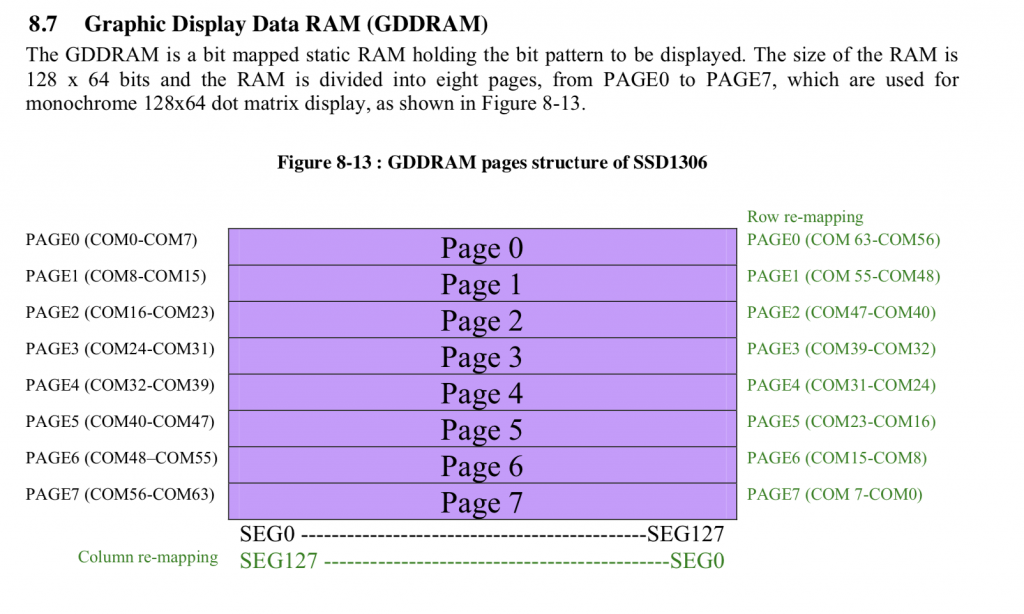
In order to actually get data to display on the screen you need to write 1’s and 0’s into the Graphics Data RAM that represents your image.  The memory is actually organized into 8 pages that are each 128 bits wide and 8 bits tall.  This means that if you write 0b10101010 to location (0,0) you will get the first 8 pixels in a column on the screen to be on,off,on,off,on,off,on,off.  Notice that I said vertical column and not row.  Here is a picture from the data sheet.  That shows the pages:

And then they show you in the data sheet that the pixels go down from the first row of the page.

In order to make the writing process easier and lower bandwidth the SSD1306 has three automatic addressing modes.

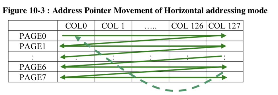
  • Horizontal – Set the page address start, end and the column start and end… bytes write 8 vertical pixels on the page. Each byte write advances the column until it wraps to the next page and resets the column to the “start”
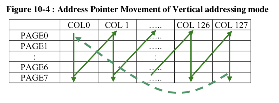
  • Vertical – Set the page address start, end and the column start and end… bytes write 8 vertical pixels on the page.  Each byte write advances the page until it wraps vertically where it increments the column and resets the page back to the start page.
  • Page – Set the page address and column start/end.  Each byte writes vertically.  Wraps back onto the same page when it hits the end column.

In Horizontal and Vertical mode you

  • Set the range of columns that you want to write (using 0x22)
  • Set the range of pages you want to write (using 0x21)
  • Write bytes

In the page mode you

  • Set the page (remember you can only write one page at a time in page mode) using 0xB0-0xB7
  • Set the start column using 0x0? and 0x1?

Here is a picture from the data sheet of horizontal address mode:

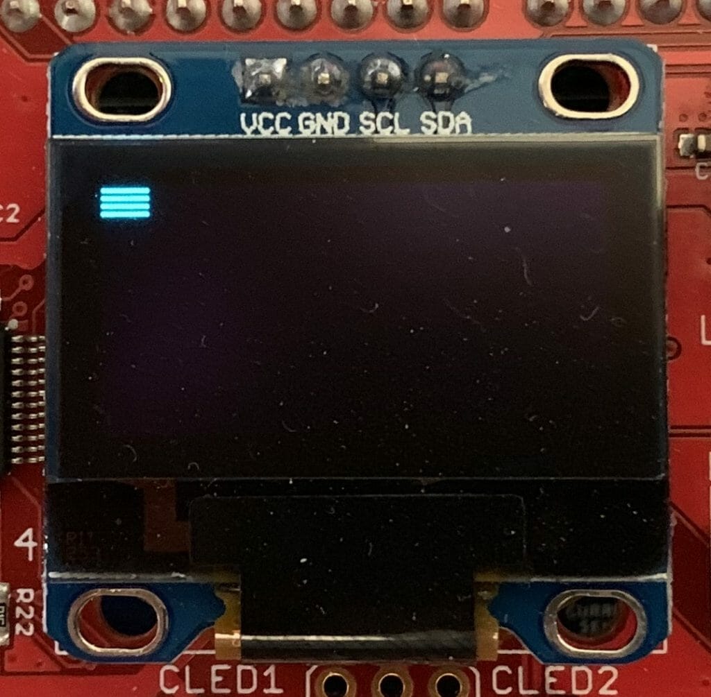
In this bit of example code I am saying to iterate through the pages 0->7… in other words all of the pages.  And to start in column 0.  This example will make 12 columns of pixels each 8 high starting a (0,0) on the screen…

    char horizontalExample[]= {
            0xAE,
            0x20, /// address mode
            0x00, // Horizontal
            0xA4,
            0xAF,
            0x22, //Set page address range
            0,
            7,
            0x21, // column start and end address
            0,
            127,
    };

    I2C_WriteCmdStream(horizontalExample, sizeof(horizontalExample));
    // Write twelve bytes onto screen with 0b10101010
    for(int i=0;i<12;i++)
        I2C_WriteData(0xAA);

Here is a picture of what it does.

Here is a picture from the data sheet of vertical address mode:

This example code sets the page range to 0–>7  (the whole screen) and the column range 0–>127 (the whole screen).  Then writes 12 bytes.  You can see it wrap at the bottom and move back to page 0 column 1.

    char verticalExample[]= {
            0xAE,
            0x20, /// address mode
            0x01, //  vertical
            0xA4,
            0xAF,
            0x22, //Set page address range
            0,
            7,
            0x21, // column start and end address
            0,
            127,
    };

    I2C_WriteCmdStream(verticalExample, sizeof(verticalExample));
    // Write twelve bytes onto screen with 0b10101010
    for(int i=0;i<12;i++)
        I2C_WriteData(0xAA); 


In page mode you just set the page and the start and end column.  0xB0 means page 0, 0xB1 means page 1… 0xB7 means page 7.

You can see that I started from column 0x78 (meaning column 120) and that it wraps back to column 0 on the SAME page.

    char pageExample[]= {
            0xAE,
            0x20, // address mode
            0x02, // Page mode
            0xA4, // Resume from ram
            0xAF, // Screen on
            0xB0, // Start from page 0
            // Start from column 0x78 aka 120
            0x08, // Column lower nibble address
            0x17  // Column upper nibble address
    };

    I2C_WriteCmdStream(pageExample, sizeof(pageExample));

    // Write twelve bytes onto screen with 0b10101010
    for(int i=0;i<12;i++)
        I2C_WriteData(0xAA);

Here is what it looks like.

Reading from the Frame Buffer

Now that you know how to write to the Frame Buffer, the next question is how do you read?  For instance if you want to turn on 1 pixel (of a byte) but leave the others alone can you do this? The answer is NO.  In serial mode the device only writes.  In all of the Graphics libraries that I have seen they handle this by having a Frame Buffer in the MCU as well.  Duplicated resources… oh well.

My Initialization Sequence

I have a function that writes an array of bytes to the command registers.  So for me to initialize the screen I just need to set up that array.  Here is my best known setup.

    const char initializeCmds[]={
        //////// Fundamental Commands
        OLED_DISPLAYOFF,          // 0xAE Screen Off
        OLED_SETCONTRAST,         // 0x81 Set contrast control
        0x7F,                     // 0-FF ... default half way

        OLED_DISPLAYNORMAL,       // 0xA6, //Set normal display 

        //////// Scrolling Commands
        OLED_DEACTIVATE_SCROLL,   // Deactive scroll

        //////// Addressing Commands
        OLED_SETMEMORYMODE,       // 0x20, //Set memory address mode
        OLED_SETMEMORYMODE_PAGE,  // Page

        //////// Hardware Configuration Commands
        OLED_SEGREMAPINV,         // 0xA1, //Set segment re-map 
        OLED_SETMULTIPLEX,        // 0xA8 Set multiplex ratio
        0x3F,                     // Vertical Size - 1
        OLED_COMSCANDEC,          // 0xC0 Set COM output scan direction
        OLED_SETDISPLAYOFFSET,    // 0xD3 Set Display Offset
        0x00,                     //
        OLED_SETCOMPINS,          // 0xDA Set COM pins hardware configuration
        0x12,                     // Alternate com config & disable com left/right
   
        //////// Timing and Driving Settings
        OLED_SETDISPLAYCLOCKDIV,  // 0xD5 Set display oscillator frequency 0-0xF /clock divide ratio 0-0xF
        0x80,                     // Default value
        OLED_SETPRECHARGE,        // 0xD9 Set pre-changed period
        0x22,                     // Default 0x22
        OLED_SETVCOMDESELECT,     // 0xDB, //Set VCOMH Deselected level
        0x20,                     // Default 

        //////// Charge pump regulator
        OLED_CHARGEPUMP,          // 0x8D Set charge pump
        OLED_CHARGEPUMP_ON,       // 0x14 VCC generated by internal DC/DC circuit

        // Turn the screen back on...       
        OLED_DISPLAYALLONRESUME,  // 0xA4, //Set entire display on/off
        OLED_DISPLAYON,           // 0xAF  //Set display on
    };

Some Other Initialization Sequences

If you look around you will find many different SSD1306 libraries.  You can run this search on github.

Here is one example from https://github.com/vadzimyatskevich/SSD1306/blob/master/src/ssd1306.c  This is pretty much the same as mine except that the author put them in some other order than the data sheet.  I am not a huge fan of “ssd1306Command( SSD1306_SEGREMAP | 0x1)” but it does work.

void  ssd1306Init(uint8_t vccstate)
{
  _font = (FONT_INFO*)&ubuntuMono_24ptFontInfo;
  
    // Initialisation sequence
    ssd1306TurnOff();
    //  1. set mux ratio
    ssd1306Command(   SSD1306_SETMULTIPLEX );
    ssd1306Command(   0x3F );
    //  2. set display offset
    ssd1306Command(   SSD1306_SETDISPLAYOFFSET );
    ssd1306Command(   0x0 );
    //  3. set display start line
    ssd1306Command(   SSD1306_SETSTARTLINE | 0x0 ); 
    ssd1306Command( SSD1306_MEMORYMODE);                    // 0x20
    ssd1306Command( 0x00);                                  // 0x0 act like ks0108
    //  4. set Segment re-map A0h/A1h    
    ssd1306Command(   SSD1306_SEGREMAP | 0x1);
    //   5. Set COM Output Scan Direction C0h/C8h
    ssd1306Command(   SSD1306_COMSCANDEC);
    //  6. Set COM Pins hardware configuration DAh, 12
    ssd1306Command(   SSD1306_SETCOMPINS);
    ssd1306Command(   0x12);
    //  7. Set Contrast Control 81h, 7Fh
    ssd1306Command(   SSD1306_SETCONTRAST );
    if (vccstate == SSD1306_EXTERNALVCC) { 
        ssd1306Command(   0x9F );
    } else { 
        ssd1306Command(   0xff );
    }
    //  8. Disable Entire Display On A4h
    ssd1306Command(   SSD1306_DISPLAYALLON_RESUME);
    //  9. Set Normal Display A6h 
    ssd1306Command(   SSD1306_NORMALDISPLAY);
    //  10. Set Osc Frequency  D5h, 80h 
    ssd1306Command(   SSD1306_SETDISPLAYCLOCKDIV);
    ssd1306Command(   0x80);
    //  11. Enable charge pump regulator 8Dh, 14h 
    ssd1306Command(   SSD1306_CHARGEPUMP );
    if (vccstate == SSD1306_EXTERNALVCC) { 
        ssd1306Command(   0x10);
    } else { 
        ssd1306Command(   0x14);
    }
    //  12. Display On AFh 
    ssd1306TurnOn();

}

Here is another example from git@github.com:lexus2k/ssd1306.git

https://github.com/lexus2k/ssd1306/blob/master/src/lcd/oled_ssd1306.c

Honestly if I had found this originally I would not have gone to all the trouble.

static const uint8_t PROGMEM s_oled128x64_initData[] =
{
#ifdef SDL_EMULATION
    SDL_LCD_SSD1306,
    0x00,
#endif
    SSD1306_DISPLAYOFF, // display off
    SSD1306_MEMORYMODE, HORIZONTAL_ADDRESSING_MODE, // Page Addressing mode
    SSD1306_COMSCANDEC,             // Scan from 127 to 0 (Reverse scan)
    SSD1306_SETSTARTLINE | 0x00,    // First line to start scanning from
    SSD1306_SETCONTRAST, 0x7F,      // contast value to 0x7F according to datasheet
    SSD1306_SEGREMAP | 0x01,        // Use reverse mapping. 0x00 - is normal mapping
    SSD1306_NORMALDISPLAY,
    SSD1306_SETMULTIPLEX, 63,       // Reset to default MUX. See datasheet
    SSD1306_SETDISPLAYOFFSET, 0x00, // no offset
    SSD1306_SETDISPLAYCLOCKDIV, 0x80,// set to default ratio/osc frequency
    SSD1306_SETPRECHARGE, 0x22,     // switch precharge to 0x22 // 0xF1
    SSD1306_SETCOMPINS, 0x12,       // set divide ratio
    SSD1306_SETVCOMDETECT, 0x20,    // vcom deselect to 0x20 // 0x40
    SSD1306_CHARGEPUMP, 0x14,       // Enable charge pump
    SSD1306_DISPLAYALLON_RESUME,
    SSD1306_DISPLAYON,
};

Debug: Test the Hardware

If a your screen is not working, the first thing to do is use a multimeter and make sure that VCC=SCL=SDA=3.3V.  (in the picture below my camera caught the screen refresh partially through… It looks fine at normal speed).  I have the red probe attached to the SCL.

I would then run the bridge control panel and make sure that the device is responding.  You can do this by pressing “List”.  In the picture below you can see that there are two devices attached to the bus,  my screen is set to 0x78/0x3C.

If you don’t have the bridge control panel then you can implement I2Cdetect using your development kit.   Read about it here.

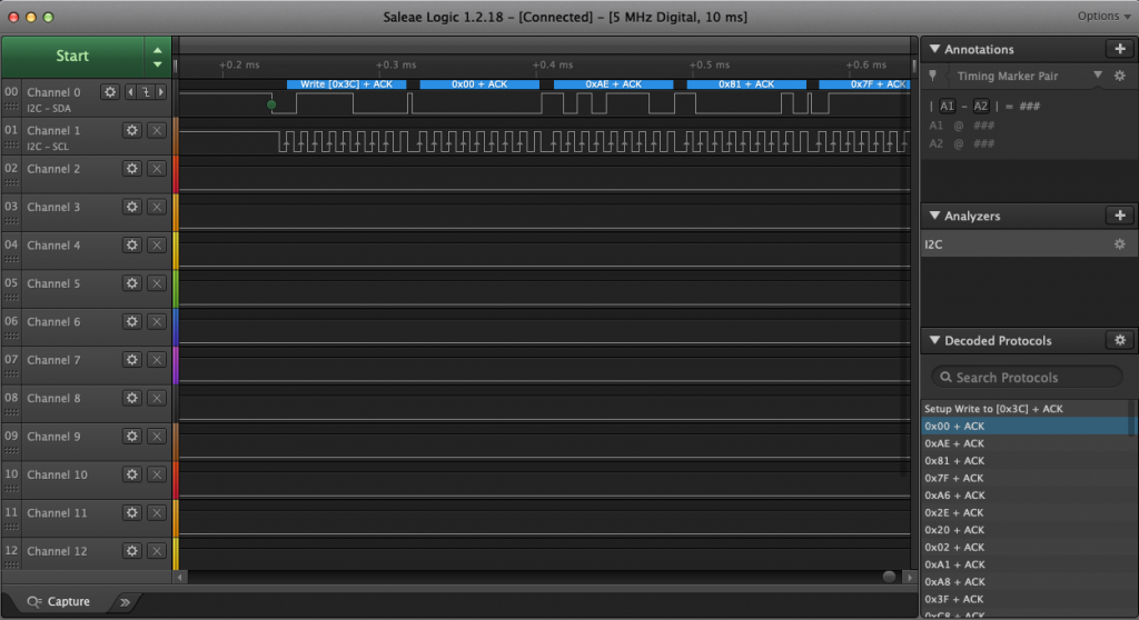
The next thing to do is attach a logic analyzer and make sure that the startup commands are coming out of your MCU correctly.  Notice that the 00, 0xAE, 0x81… are exactly the configuration sequence that I wrote in the driver code above.

Debug: Test the Firmware

If your screen is still not working here are some problems and what to do about them.

  • Speckled Screen
  • Solid Screen
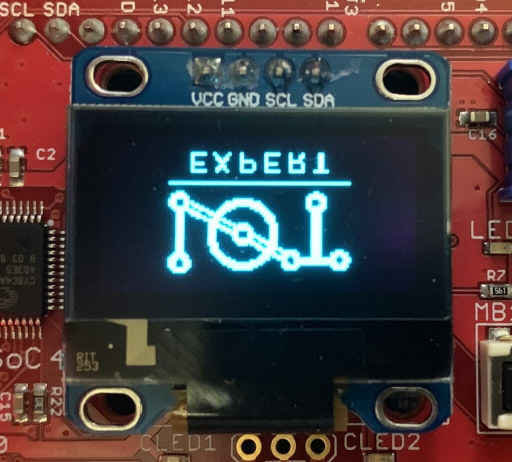
  • Screen Flipped in the Y direction
  • Screen Flipped in the X Direction
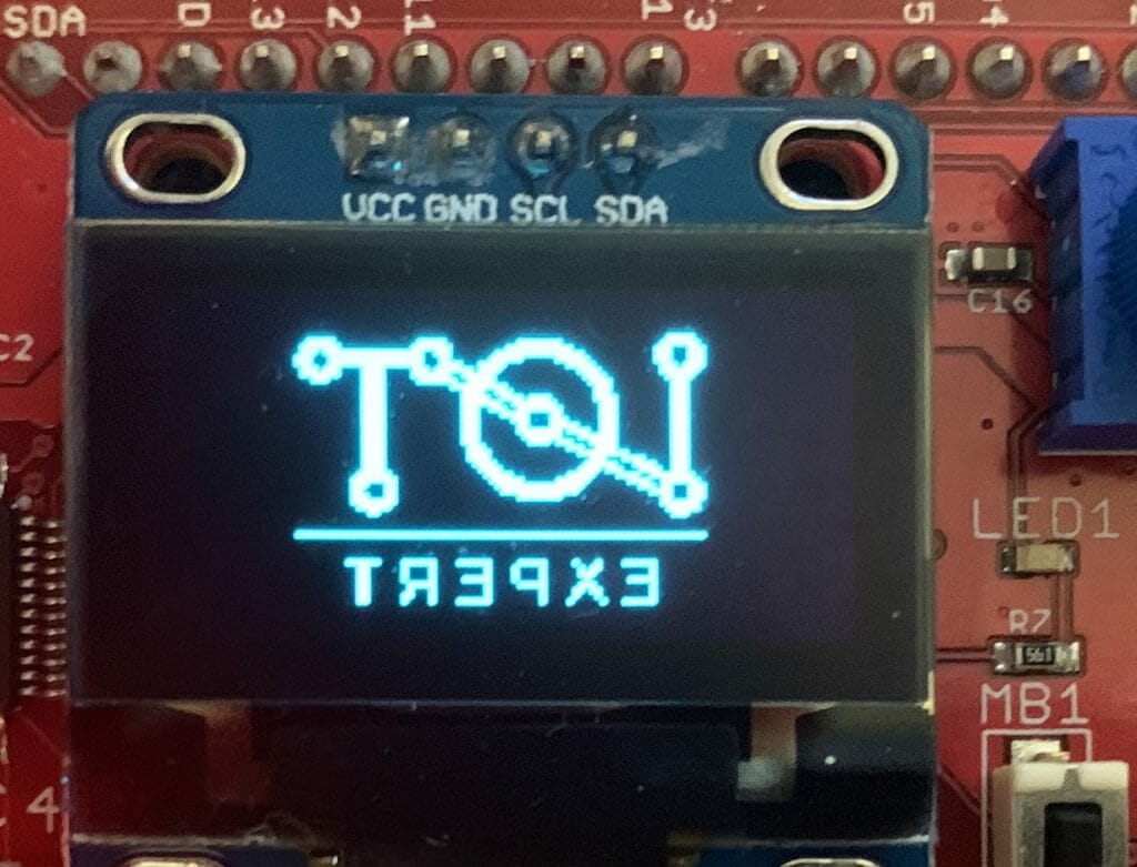
  • Screen Flipped in both Directions
  • Screen is Inverted
  • Image is Partially off the Screen
  • Image is Wrapped on the Screen
  • Black Screen
  • Screen Has Gone Crazy

Speckled Screen

If you have the speckled screen this means that your screen is displaying an uninitialized frame buffer which the SSD people call the GDDRAM.  These are basically the random 0 and 1s that are the startup values in the SSD1306.  If this is happening then your graphic data is probably not being transferred between your MCU and the SSD1306.  This almost certainly means you have a problem in your porting layer.

Speckled Screen

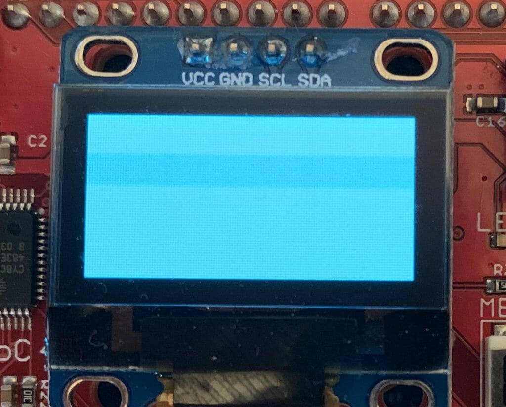
If your screen is solid white that probably means you turned the screen back on without resuming from the graphics ram.  You did this:

OLED_DISPLAYALLONIGNORE,  // 0xA5, //Set entire display on/off

instead of this:

OLED_DISPLAYALLONRESUME,  // 0xA4, //Set entire display on/off

Screen Flipped in the Y direction

The commands C0/C8 set the direction in which the com lines are scanned.  Either from top to bottom or bottom to top.  Change C0–>C8 to the other way.
#define OLED_COMSCANINC                               0xC0
#define OLED_COMSCANDEC                               0xC8

Screen Flipped in the X Direction

In the X-Direction the A0/A1 set the configuration of scanning.  Try using A0–>A8 or the other way.

// X Direction Scanning 
#define OLED_SEGREMAPNORMAL                           0xA0
#define OLED_SEGREMAPINV                              0xA1

Screen Flipped in both Directions

If it is flipped in both X and Y direction then flip both of the direction registers.

// Y Direction
#define OLED_SEGREMAPNORMAL                           0xA0
#define OLED_SEGREMAPINV                              0xA1

// X Direction
#define OLED_COMSCANINC                               0xC0
#define OLED_COMSCANDEC                               0xC8

Screen is Inverted

If your screen is inverted then try A8–>A6

#define OLED_DISPLAYNORMAL                            0xA6
#define OLED_DISPLAYINVERT                            0xA7

Image is Partially off the Screen

If your image is off the screen the you probably have the wrong value for MULTIPLEX.

#define OLED_SETMULTIPLEX                             0xA8

The parameter is supposed to be the number of lines on the screen -1.  In my case the screen is 128×64 so my valued should be 63 aka 0x3F

        OLED_SETMULTIPLEX,        // 0xA8 Set multiplex ratio
        0x3F,                     // Vertical Size - 1

Image is Wrapped on the Screen

// Double byte CMD image wrap ...probably should be 0
#define OLED_SETDISPLAYOFFSET                         0xD3

The offset value allows the board designer to hook up the rows in a crazy fashion.   My screen has the top row to the top row number.

        OLED_SETDISPLAYOFFSET,    // 0xD3 Set Display Offset
        0x00,                     //

\

Black Screen

If you screen is totally dead…

Then the charge pump may be off

        //////// Charge pump regulator
        OLED_CHARGEPUMP,          // 0x8D Set charge pump
        0x14,                     // VCC generated by internal DC/DC circuit

or maybe the screen is off… try turning it on.

        OLED_DISPLAYON,           // 0xAF  //Set display on

or maybe you haven’t displayed anything. The screen is off trying sending a screen invert

#define OLED_DISPLAYINVERT                            0xA7

The Screen Has Gone Crazy

The register 0xDA SetComPins register will make some crazy results of it isn’t set correctly.  For my 0.96″ inch screen it needs to be set to 0x12

// Double Byte Hardware com pins configuration
#define OLED_SETCOMPINS                               0xDA
// legal values 0x02, 0x12, 0x022, 0x032

This is what happens with 0x02 [If you see the note below from Ivan, 0x02 is apparently for 128×32 and this screen is 128×64=0x12]

And 0x22

Finally 0x32

This was absolutely the craziest rabbit hole that I have ventured down. Nicholas has talked to me 10 times about doing this and he thinks I’m crazy.  Oh well.

IoT Expert Logo -> EPD – Bitmap Madness (Part 2)

Summary

In the last article I showed you how to display a bitmap in the Segger format.  In this article I will show you how to convert a BMP to a “C” file and then display it using the Segger GUI_BMP_Draw() API.

To this I will follow these steps:

  • Use GIMP to Export a Black and White Logo
  • Convert the BMP to a “C” array using Bin2C
  • Add the C to the project and fix up the project

Use GIMP to Export a Black and White Logo as BMP

As in the last article, Ill use GIMP to manipulate the IoT Expert.  First, Ill load the logo from the PNG file.

Then I will convert the PNG to a black and white only image.  This will be a 1-bit per pixel indexed image.  Indexed means that instead of ARGB (aka 32 bits for each pixel), that the color of each pixel will be referenced via an index into a color table.  For instance the color table might look like this:

Index Value Color
0 0xFF000000 Black
1 0xFFFFFFFF White

The BMP file will then have a color table (like the one above) and each pixel value will be an index into the table.  It turns out that these color tables must have  2^n rows where n is the number of bits in the index.  Also with the BMP format any bitmaps with 24 bits per pixel will not have a color table.

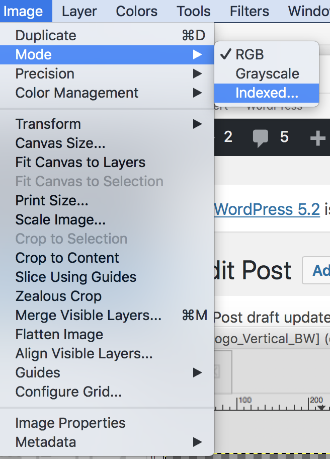
Gimp can convert an image to indexed.  To do this, click  Image–>Mode–>Indexed…

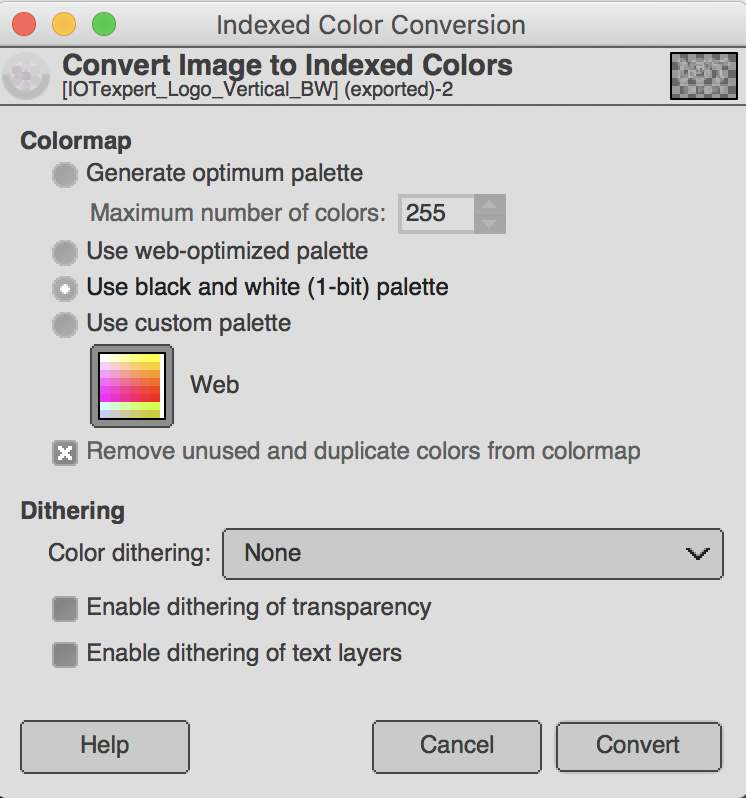
On this screen you will be given the option to specify the color indexes.  Notice that there is a “black and white only” option.

Once you have made the conversion you can see that image is now indexed.

On that screen you could have converted the image to indexed with up to 256 colors (but I choose 2 by using the Use black and white (1-bit) palette.

The next step is to export to a BMP using “File–>Export As…”

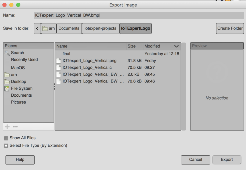
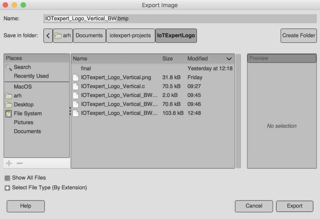
I set the file name to “IOTexpert_Logo_Vertical_BW.bmp”.  Gimp does its magic by using the file extension.  In this case “bmp” creates a Microsoft BMP file.

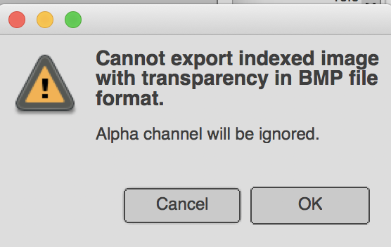
When I hit export I get this dialog box (which I had no idea what it meant when I started). For now click “OK”

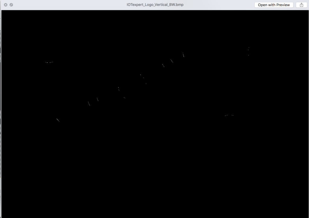
Once the file is exported this is what I get.  OK… is not very helpful.  What happened?

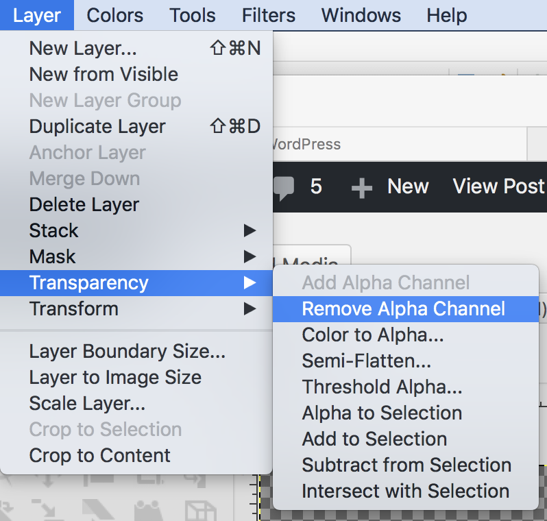
The answer is that an Indexed BMP does not support Alpha.  So, GIMP ditched the Alpha, which turned everything that wasnt black to the background color, which is black. So, what is the deal with the Alpha channel?  Alpha is how transparent everything is.  You can get rid of it using Layer–>Transparency–>Remove Alpha Channel

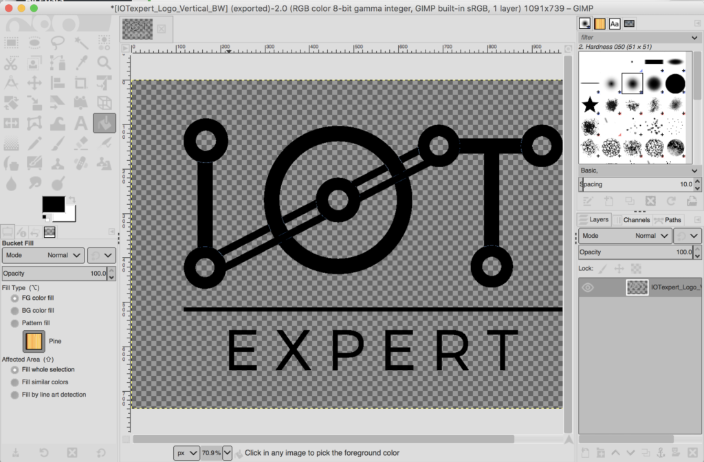
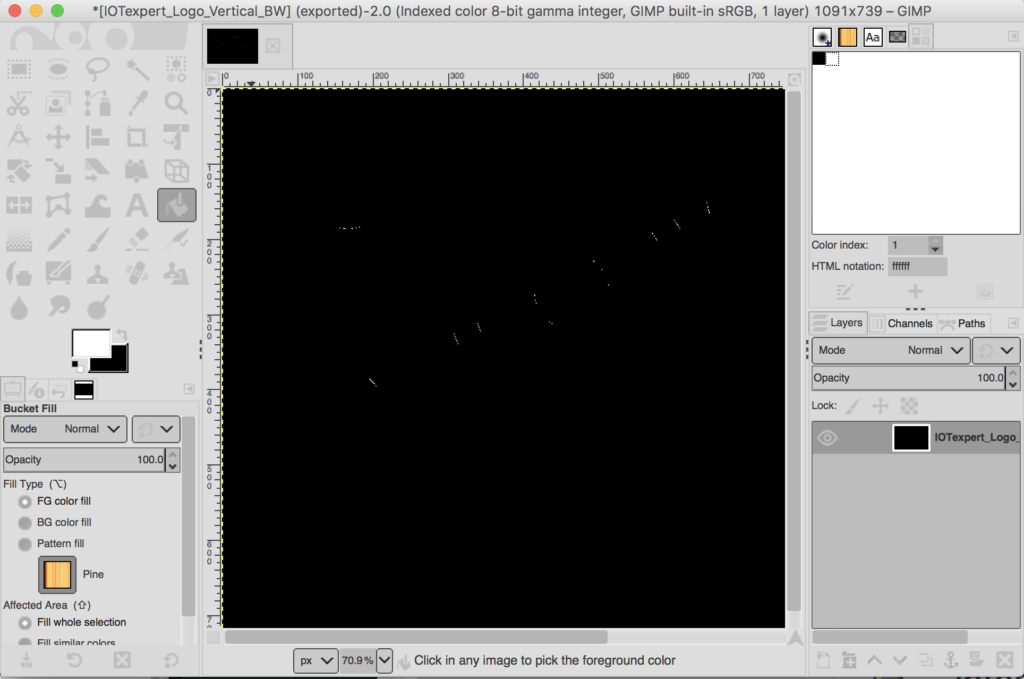
Which once again turns my image black.  But why?  On the left hand side of the screen you will see the foreground/background colors.  And you will notice that the background is black.

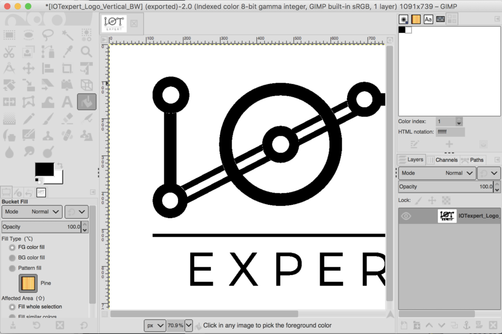
To fix the problem undo the remove alpha.  Then click the little back and forth arrow to turn the background white.  Then re-remove the alpha.  Now that problem is fixed.

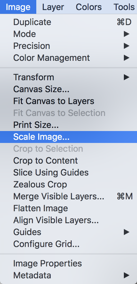
Now, I can shrink it to the right size using Image–>Scale Image…

Then pick the 276 width (aka the same width as the EPD screen)

Now do “File–>Export As..” with a “.bmp” file name extension.  This time it doesn’t ask me about the transparency.

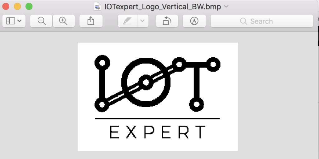
And, now I have a nice BMP file.  Here is the view from the preview in Mac.

So, how do I get a BMP file into my program?  Well, I need turn it into an array of bytes.  And to do that…

Segger Bin2C

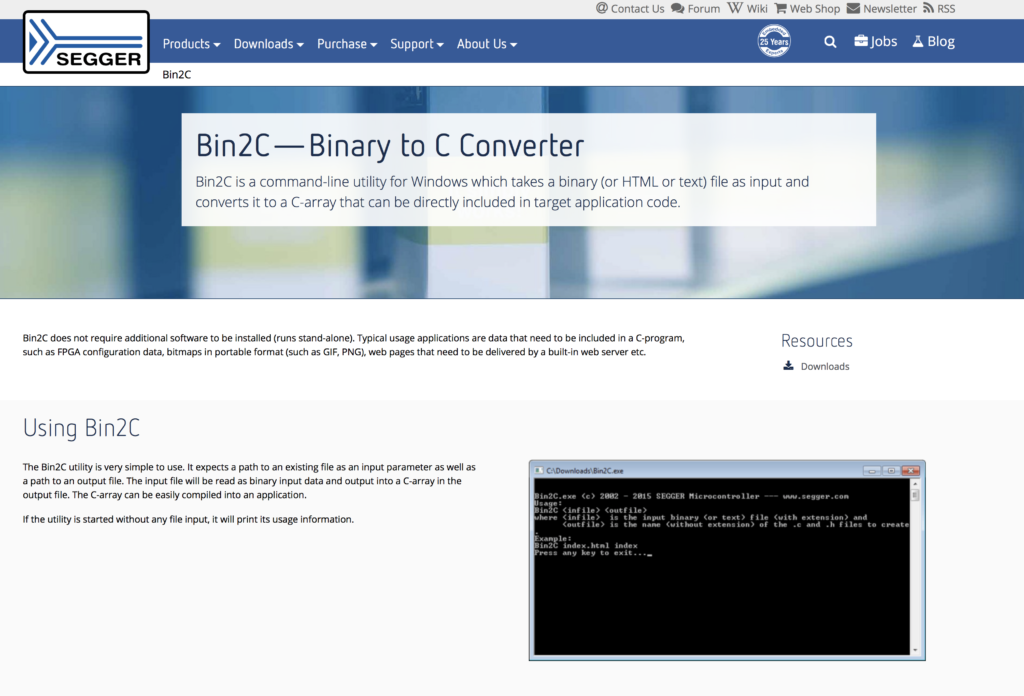
One of the utility programs that Segger provides is called “Bin2C” which can read in a file and turn it into an array of bytes in “c” format.  You can download it here.

When I run it, first I select the file, then press “Convert”

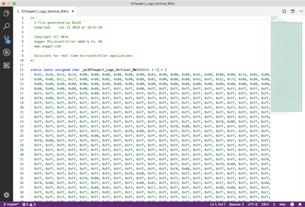
And it generates a nice array of bytes.

Update the Project

To use the array, first copy the file into your project.  You notice that the array is defined as “static” which means that it is not accessible from other files.  Remove that.  Now edit the eInkTask.c and

  1. Add an extern reference to the array of bytes
  2. Make a call to “GMP_BMP_Draw()” to display the logo
extern unsigned char _acIOTexpert_Logo_Vertical_BW[6862UL + 1];
void ShowIoTScreen(void)
{
	GUI_Clear();
	GUI_BMP_Draw(_acIOTexpert_Logo_Vertical_BW, 0,0);
	/* Send the display buffer data to display*/
	UpdateDisplay(CY_EINK_FULL_4STAGE, true);
	while(1)
		vTaskDelay(100);
}

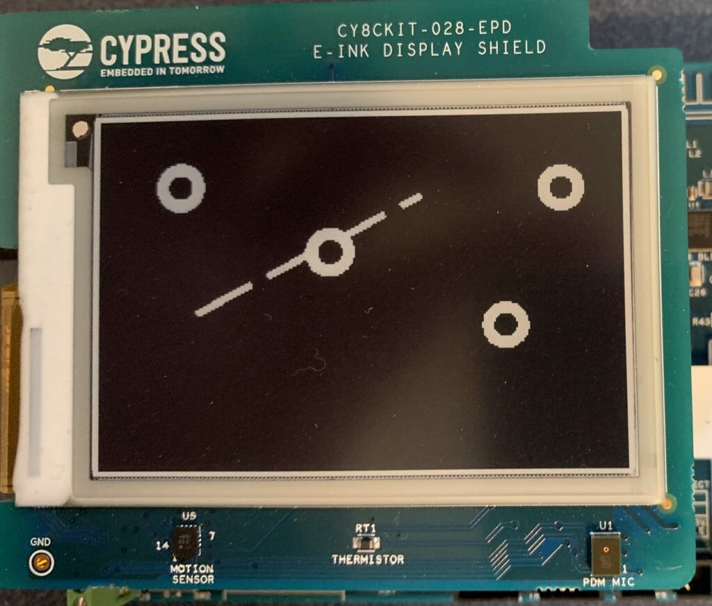
When I program the kit I get this… all black.


But why?  I didn’t know the answer.  So I assumed that it must be something to do with me and my understanding of bitmaps.  In the next article I’ll tell you all about that journey.  But after a day or two of learning about bitmap file formats I was convinced that it wasn’t me.  So I started looking around on the web and I found this thread on Segger’s forum.

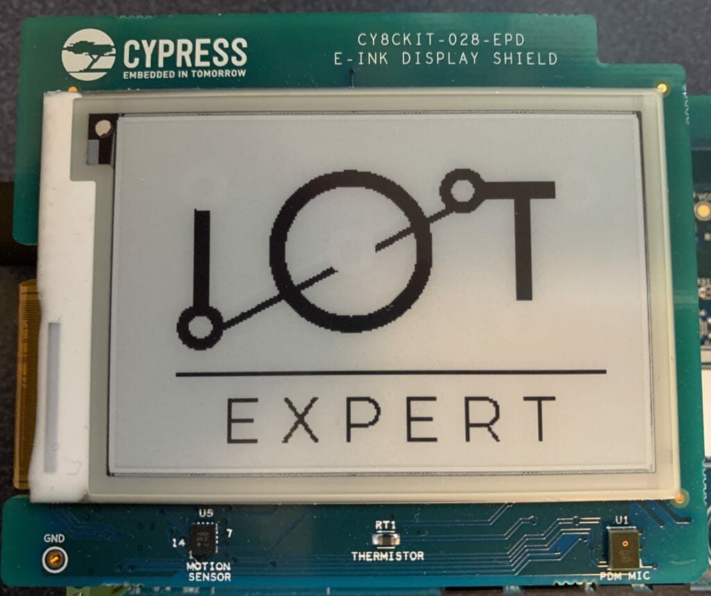
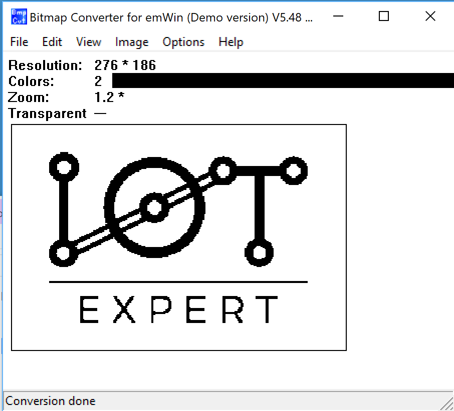
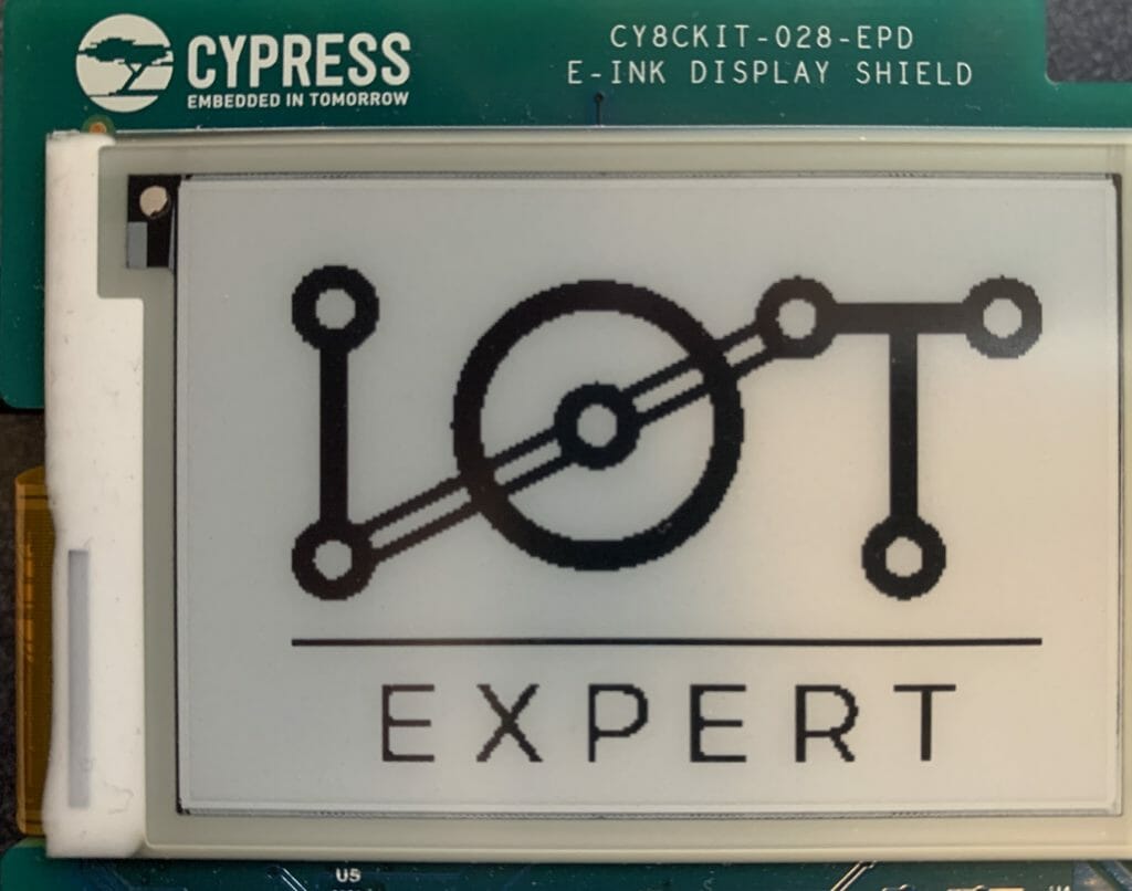
And, when I got to work the next Monday I called an amazing engineer that works for Cypress in Ukraine. He provided me a v5.48 which sure enough fixed the problem.  When I program that, looks like things are working with bitmaps:

Unfortunately that means that we (Cypress) have a released version of Segger emWin that is broken.  This will be fixed with an updated version soon, but for now if you are stuck send me an email and I’ll help you.

The next article is a deep dive into the BMP format.

IoT Expert Logo –> EPD – Bitmap Madness (Part 1)

Summary

In the last article I showed you a bunch of things about programming the Pervasive EPD eInk Display that is attached to the CY8CKIT-028-EPD.  You might have noticed in the first video I have a screen that shows the IoT Expert Logo.  Simple right?  Yes you would think, but it actually turned out to be quite a pain in the ass!  This article is my journey through bit maps.  It is hardly canonical, but hopefully it will help you.

In this article I will specifically walk you through:

  • The IoT Expert Logo
  • Segger emWin Bitmap Drawing APIs
  • Segger Bitmap Converter
  • Updating a Project to draw a Segger Bitmaps
  • Converting a Color Bitmap to Black and White
  • Using GIMP to Fix B/W Conversion

In the next two articles I will address drawing bitmaps that are in the Windows BMP format and PNG format.

The IoT Expert Logo

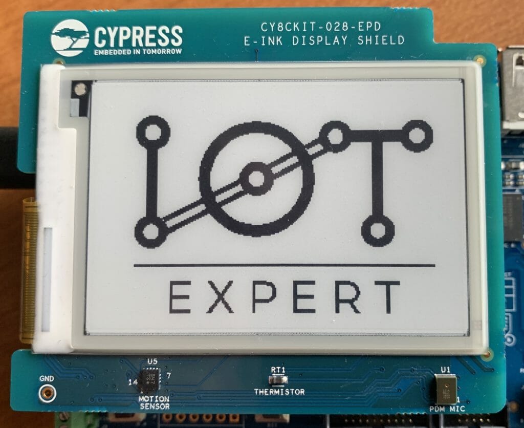
If you guys remember, in early 2017, I ran a design contest to create a logo for the IoT Expert website.  You can read about it here and here.  When it was over, I had a bunch of different images including this one which is a 1091×739 PNG file with what I thought was five colors but is actually nine (which I discovered during this journey)

OK, thats cool.  But how do I get that onto the eInk screen which is 276×176 and black and white?

emWin Bitmap Drawing APIs

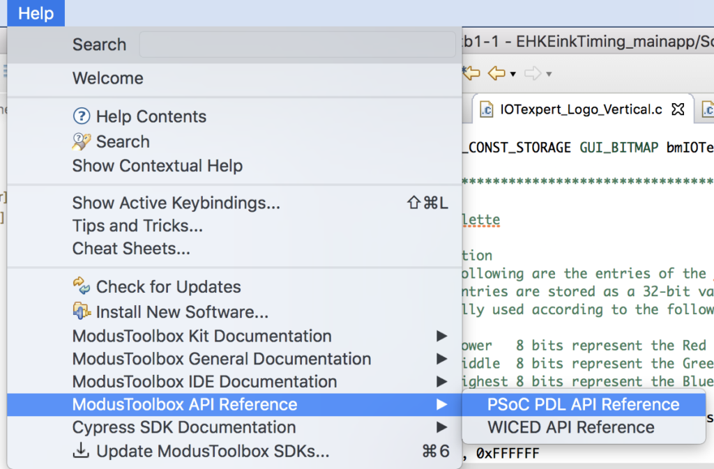
I started by looking at the Segger emWin documentation which you can either get directly from the Segger website here.  Or you can find it inside of Modus Toolbox.  Select “Help–>ModusToolbox API Reference–>PSoC PDL Reference”

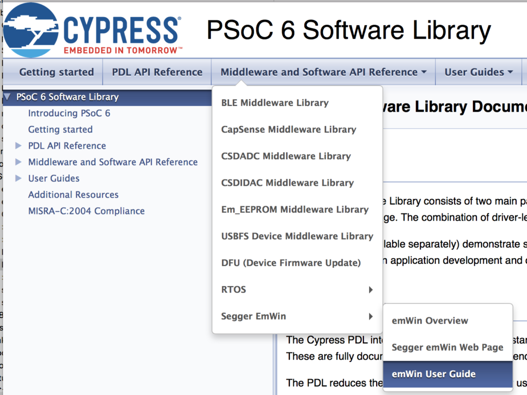
Then pick “Middleware and Software API Reference –> Segger emWin –> emWin User Guide”

From the documentation you see that emWin can display bitmaps in the emWin format using the APIs GUI_DrawBitmap.  This section actually goes on for more than another page worth of APIs.  The API that I will focus on in this article is GUI_DrawBitmap()

You can also display bitmaps that are in GIF, PNG, BMP or JPEG format.

Bitmap Converter for emWin

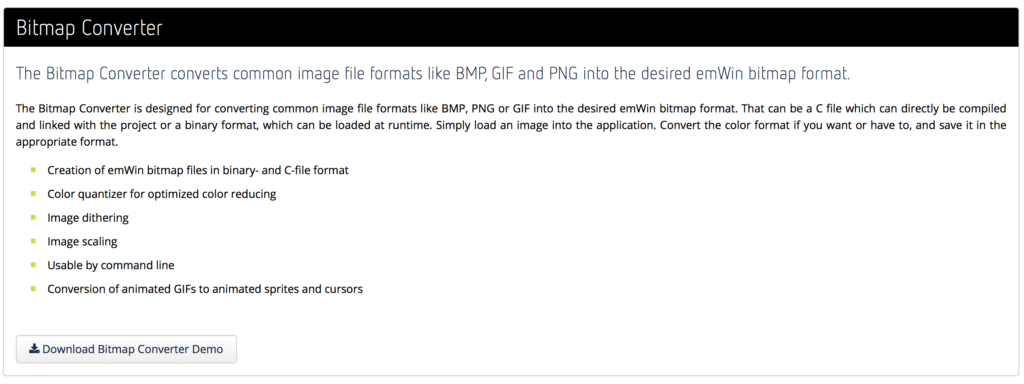
I suppose the first question is, “How do I get a bitmap from my computer in PNG format into the Segger Bitmap format?”  Well, it turns out that Segger has a program called Bitmap Converter for emWin.

This is a pay program, but you can download it to try it out.  It is sort of an old-school windows program.  So I installed it on parallels on my mac.  When you run it the first time it reminds me that this is not for production.  Got it!

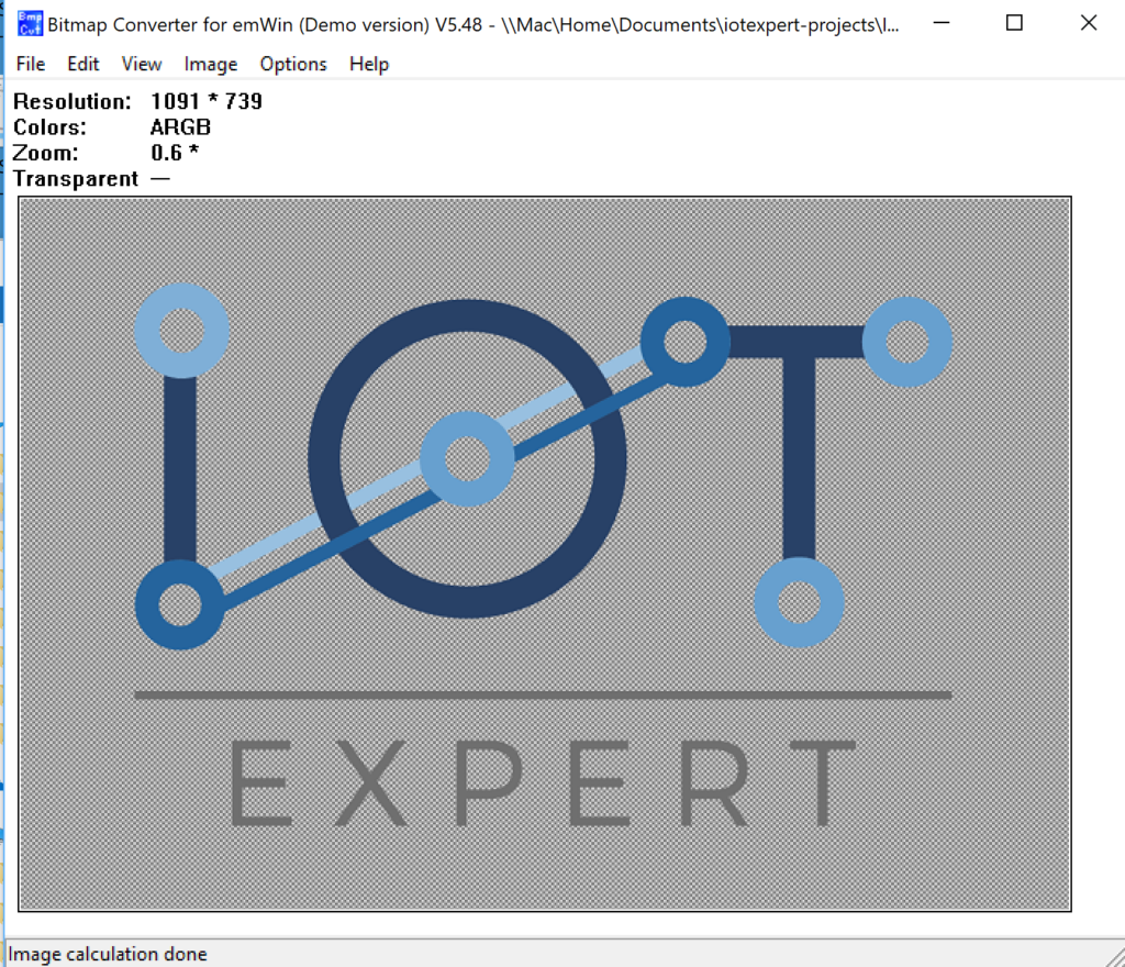
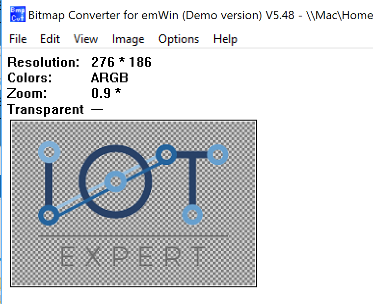
I start by opening the PNG file of my logo.  Notice that it says the file is 1091 by 739 and in “ARGB” colors.  “ARGB” means Alpha, Red, Green and Blue. (more on this later).

On the Image menu I start by picking “Scale..” to reduce the size.

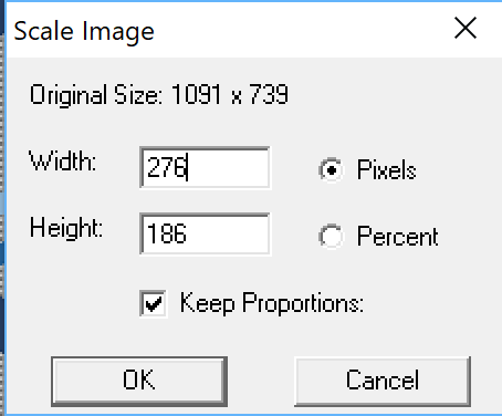
I pick out 276 wide and it keeps the aspect ratio the same, which results in a height of 186 (actually 10 pixels to high)

After clicking OK I get this.

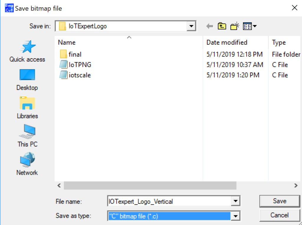
Now, I want to take that bitmap and turn it into a “C” file that has the right data structures.  To do that pick “Save As..”

Then pick “C” bitmap file (*.c)

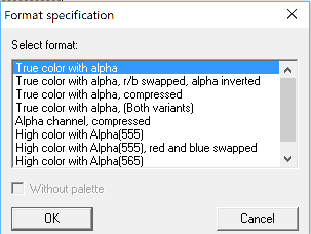
Now, it asks me this question, which I didn’t really know the answer to. (more on this later) but I let the default be “True color with alpha”

This created a “C” file called IOTexpert_Logo_Vertical.c” which seems to be OK.

Updating a Project to draw a Segger Bitmap

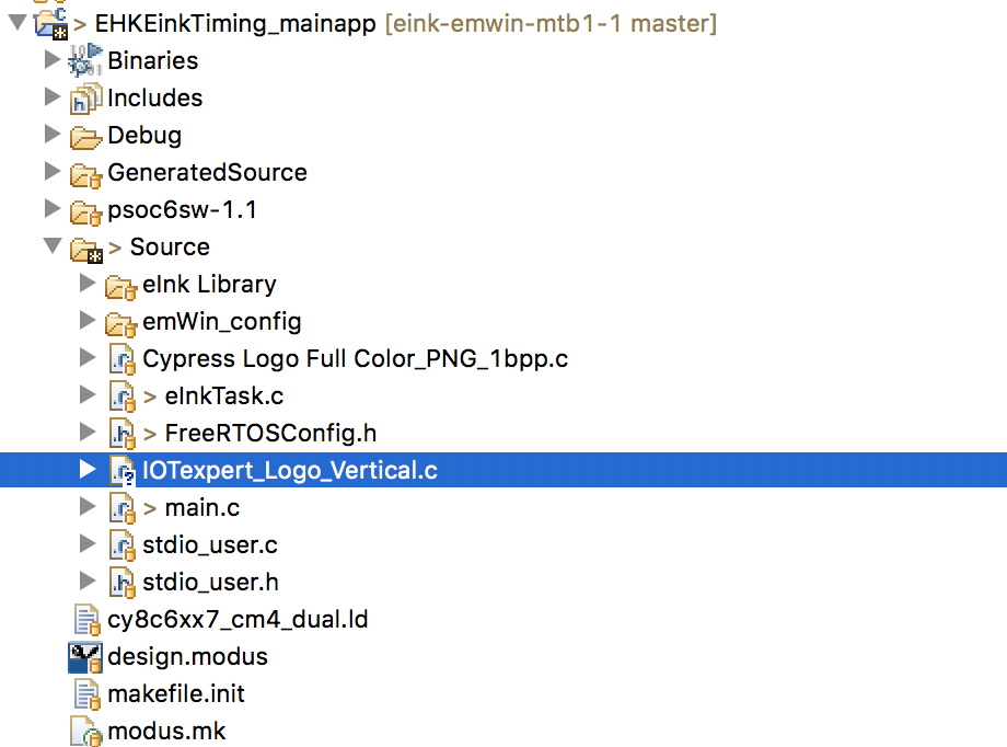
Rather than make a new project.  I start with the project from the previous article.  I use the finder to copy/paste the c file into my project.  You can see it below.

Then I double click on the file.  Here is the top.  Notice it reminds me that this is demo only.  And it gives me a little bit of information about the bitmap.  Specifically the width and height.  As well as the number of colors which is 32 bits per pixel.  It turns out that this is 4-bytes per pixel.  The first byte is Alpha and then one byte each for Red, Green and Blue.  Notice that it also declares an extern structure “extern GUI_CONST_STORAGE GUI_BITMAP bmIOTexpert_Logo_Vertical”.  This is exactly the right type to call the GUI_Drawbitmap function.

/*********************************************************************
*                SEGGER Microcontroller GmbH & Co. KG                *
*        Solutions for real time microcontroller applications        *
*                           www.segger.com                           *
**********************************************************************
*                                                                    *
* C-file generated by                                                *
*                                                                    *
*        Bitmap Converter for emWin (Demo version) V5.48.            *
*        Compiled Jun 12 2018, 15:10:41                              *
*                                                                    *
*        (c) 1998 - 2018 Segger Microcontroller GmbH                 *
*                                                                    *
*        May not be used in a product                                *
*                                                                    *
**********************************************************************
*                                                                    *
* Source file: IOTexpert_Logo_Vertical                               *
* Dimensions:  276 * 186                                             *
* NumColors:   32bpp: 16777216 + 256                                 *
*                                                                    *
**********************************************************************
*/

#include <stdlib.h>

#include "GUI.h"

#ifndef GUI_CONST_STORAGE
  #define GUI_CONST_STORAGE const
#endif

extern GUI_CONST_STORAGE GUI_BITMAP bmIOTexpert_Logo_Vertical;

static GUI_CONST_STORAGE U32 _acIOTexpert_Logo_Vertical[] = {
  0xFFFFFFFF, 0xFFFFFFFF, 0xFFFFFFFF, 0xFFFFFFFF, 0xFFFFFFFF, 0xFFFFFFFF, 0xFFFFFFFF, 0xFFFFFFFF, 0xFFFFFFFF, 0xFFFFFFFF, 0xFFFFFFFF, 0xFFFFFFFF, 0xFFFFFFFF, 0xFFFFFFFF, 0xFFFFFFFF, 0xFFFFFFFF, 0xFFFFFFFF, 0xFFFFFFFF, 0xFFFFFFFF, 0xFFFFFFFF, 0xFFFFFFFF, 

In my project I create a new function called “ShowIoT” screen.  This will just clear the screen, update the display, then draw the bitmap, then update the screen, then wait forever.  In order for my file to know about the bitmap I copy the “extern GUI_CONST_STORAGE GUI_BITMAP bmIOTexpert_Logo_Vertical” into my file.  Typically this declaration would be in a “.h” file that was paired with the “.c” file.  Oh well.

extern GUI_CONST_STORAGE GUI_BITMAP bmCypressLogoFullColor_PNG_1bpp;

void ShowIoTScreen(void)
{
    /* Set foreground and background color and font size */
    GUI_Clear();
    GUI_SetBkColor(GUI_WHITE);
    GUI_SetColor(GUI_BLACK);
    UpdateDisplay(CY_EINK_FULL_4STAGE, true);

    GUI_DrawBitmap(&bmCypressLogoFullColor_PNG_1bpp, 0, 0);

    /* Send the display buffer data to display*/
    UpdateDisplay(CY_EINK_FULL_4STAGE, true);
    while(1)
    	vTaskDelay(100);
}

When I build the project I find out.. HOLY CRAP my project is now 270648 bytes.  Wow.

=========================================
== Application CM0+ Memory ==
=========================================
code:6560	sram:1724


=========================================
== Application CM4 Memory ==
=========================================
code:270648	sram:278508

Why is this?  Simple, by looking at the linker map you can see that the array of data for the bitmap is 0x32220 which is also known as 205344 bytes.  Im going to have to figure out something better than that.

 .rodata._acIOTexpert_Logo_Vertical
                0x0000000000000000    0x32220 ./Source/IOTexpert_Logo_Vertical.o

When I program the screen I get this… which obviously is jacked up.

But what to do?

Converting a Color Bitmap to Black and White

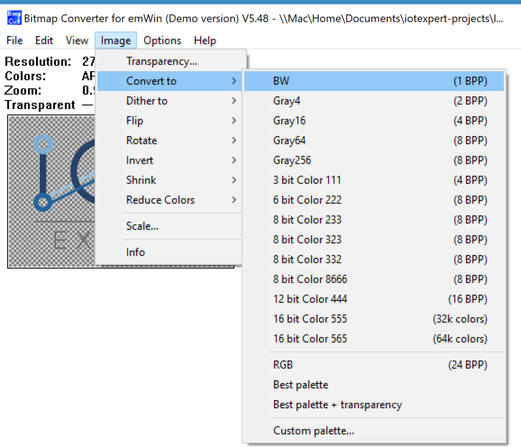
Well instead of a color image (32 bits-per-pixel) let’s use the Bitmap Converter for emWin (Demo version V5.8 to convert the image to BW.  On the Image –>Covert to –> BW (1BPP)

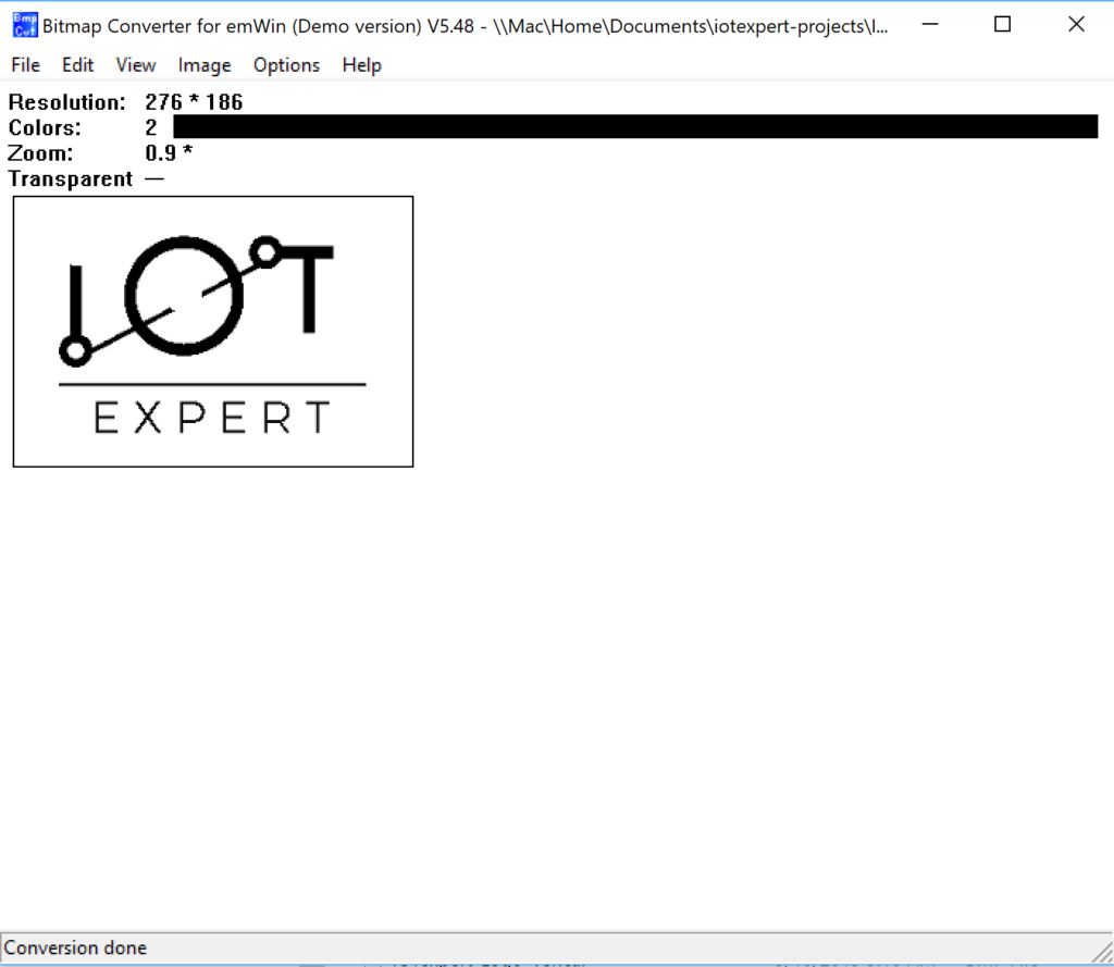
After running that I get this. (what happened to my logo?).


After exporting the new image to a “.c” file I go have a look.  OK it isnt very often that I learn something new about “C”.  But look at this.  Apparently you can represent binary data as “X” and “_” when initializing arrays.  Who knew?

static GUI_CONST_STORAGE unsigned char _acIOTexpert_Logo_Vertical[] = {
  XXXXXXXX, XXXXXXXX, XXXXXXXX, XXXXXXXX, XXXXXXXX, XXXXXXXX, XXXXXXXX, XXXXXXXX, XXXXXXXX, XXXXXXXX, XXXXXXXX, XXXXXXXX, XXXXXXXX, XXXXXXXX, XXXXXXXX, XXXXXXXX, XXXXXXXX, XXXXXXXX, XXXXXXXX, XXXXXXXX, XXXXXXXX, XXXXXXXX, XXXXXXXX, XXXXXXXX, XXXXXXXX, 
        XXXXXXXX, XXXXXXXX, XXXXXXXX, XXXXXXXX, XXXXXXXX, XXXXXXXX, XXXXXXXX, XXXXXXXX, XXXXXXXX, XXXX____,

When I build the project I find that it is much much smaller.  Thats good.

=========================================
== Application CM0+ Memory ==
=========================================
code:6560	sram:1724


=========================================
== Application CM4 Memory ==
=========================================
code:69744	sram:278492

And I find that the image occupies 0x196e bytes (also known as 6510 in decimal).  Much better.

.rodata._acIOTexpert_Logo_Vertical
                0x000000001000f880     0x196e ./Source/IOTexpert_Logo_Vertical.o

But, when I program the board, my image is jacked up.  I suppose that I shouldn’t be surprised as thats what the program showed me as well.

Using GIMP to Fix B/W Conversion

My lab assistant, Nicholas, looked at the image and said.  The problem is that when you converted it to black and white, the light colors in the logo turned to white instead of black.  OK.  How do I fix it?  Simple, install GIMP and edit the PNG.  GIMP is GNU Image Processor and is a program that acts like Adobe Photoshop.

Start by opening up the logo and it tell me nearly the same thing as the BitMap converter program.

On the left side of the screen there is a “bucket” icon which will pour color into regions of the image.  So, to make things work I pour black everywhere there is color.  That little black white thing specifies the foreground and background colors.

Now I take the file and export it back to an PNG.

When you pick “PNG” you need to give it some options.  Which I took also as default.

Now when I open it up in the Bitmap Converter it looks all black and white.  BUT notice that it is still “ARGB”

So, I convert it to black and white.

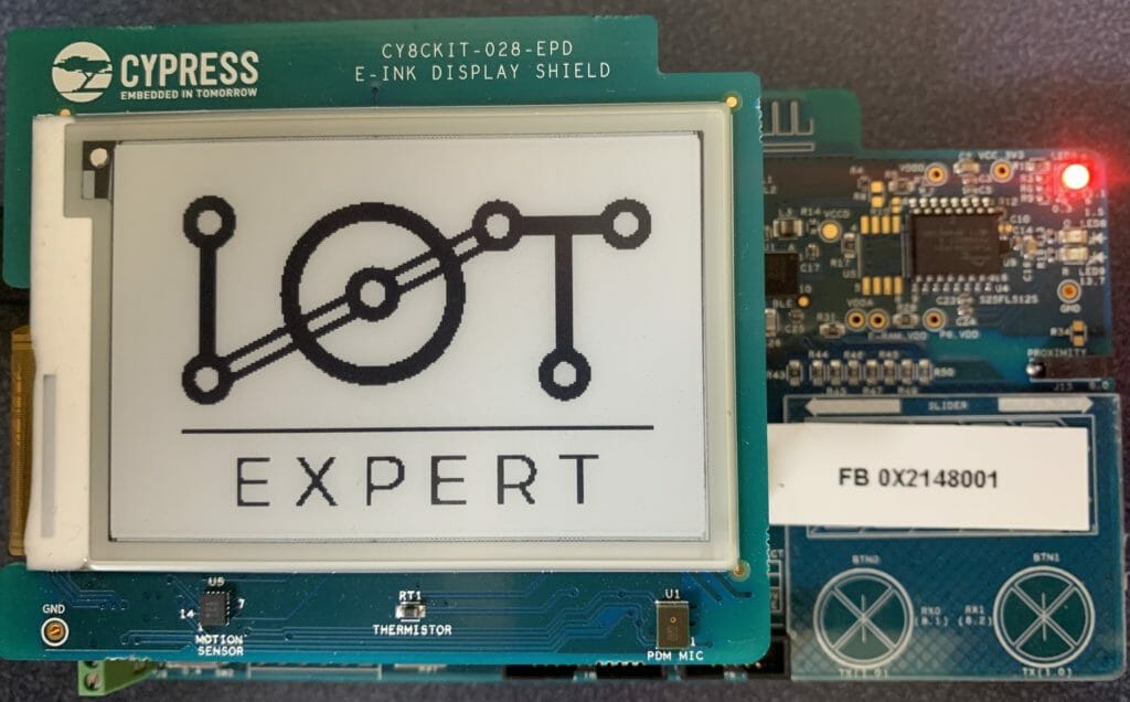
Then I follow the same process to program the development kit. (export C file, copy into project, fix up the extern and build/program).  Excellent.  Now my image is good.

In the next article I will talk more about the Bitmap format, and colors, and Alpha.  I will then show you how to use some of the other APIs.

CY8CKIT-028-EPD: How Does The Driver Work?

Summary

Before I finish this series there are two more issues which I would like to address.  First, I want to walk you through the schematic and show you how things are connected.  And second, I want to talk about the “Update Scheme”.  Unfortunately, there are a couple of other things that I would like to dig into, but for now this article will be the last.  But, I will leave a few links at the end of the article which will give you a hint about other things that I might be interested in.

Electrical Interface

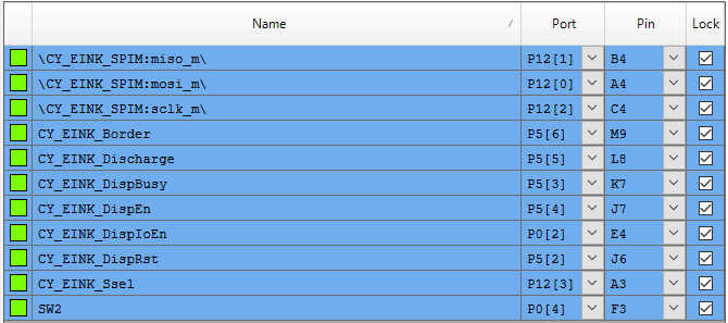
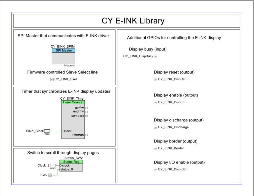
If you follow back through the previous articles you will notice that there are several different pins.  Here is the pin assignment from PSoC Creator.

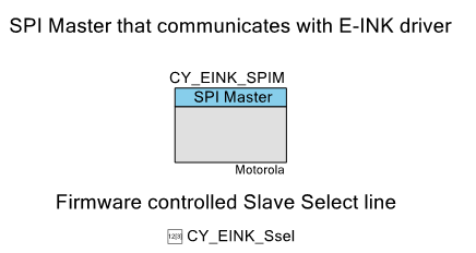
But what do they do?  If you look at the list you will see that four of them are to control the SPI interface to the G2 display driver. (miso, mosi, sclk, CY_EINK_Ssel).  The rest of them Ill go one by one through.

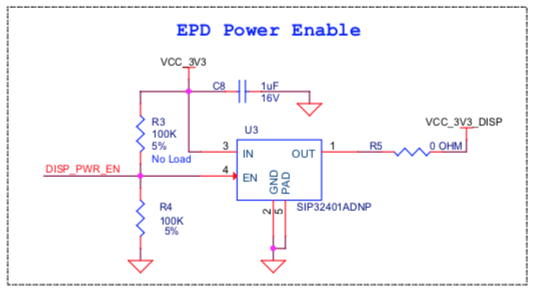
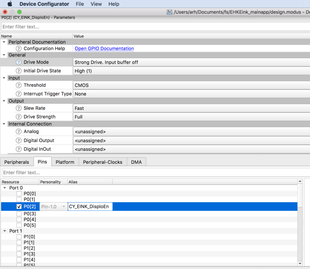
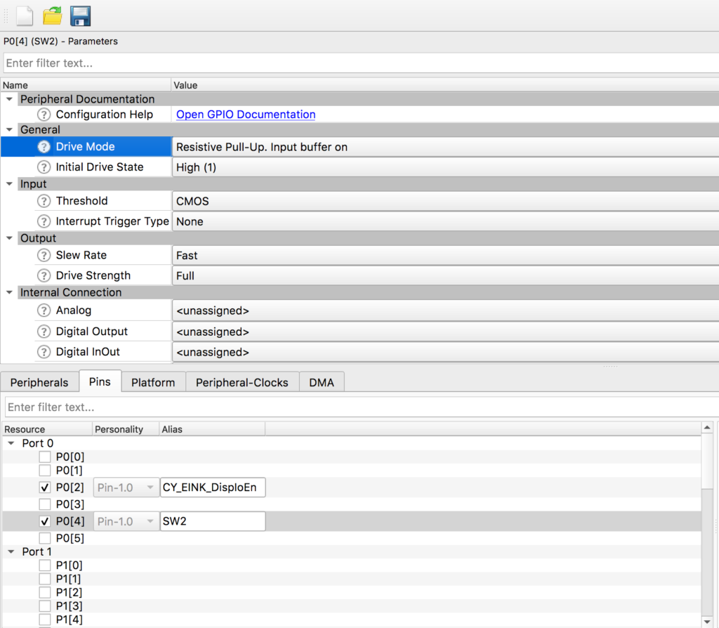
First is the pin called “CY_EINK_DispEn”.  This pin really should have been called “DISP_PWR_EN” so that it matched the actual shield schematic.  This is a digital output pin which is connected to a Vishay sip32401a 1.1 V to 5.5 V, Slew Rate Controlled Load Switch.  Simply a power switch for the display.  Notice in the schematic that there is a 100K pulldown resistor connected to the enable which means that by default the power is off to the display.  Also notice that R3 is a “No Load” pullup resistor.  You could remove R4 and load R3 to make the power on by default… which I don’t think that you would actually ever do as if you are using an EPD you probably care about power.

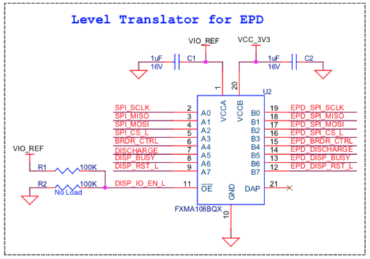
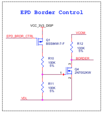
The next pin is called “CY_EINK_DispIoEn”.  This is a digital output pin which is connected to “DISP_IO_EN_L” on the shield.  This is simply the I/O enable of a Fairchild FXMA108BQX level shifter.  This allows the PSoC to run at lower voltages (e.g. 1.8v) than the 3.3v required by the EPD G2 driver chip.  This would also enable a chip to run at a higher voltage (e.g. 5V) if you were using a 5V capable PSoC (e.g. all of the PSoC 4s).  The schematic uses the same pullup/down scheme that was used on the power switch above.

The next pin is called “CY_EINK_Discharge” and is a digital output from the PSoC.  Notice that when the PSoC drives this pin high that it will enable two power transistors and will short “VGH” and “VDH” to ground.

If you read the “E-paper Display COG Driver Interface Timing for 1.44”,1.9”,2”,2.6” and 2.7” EPD with G2 COG and Aurora Mb Film” document you will see this note:

And a bit later on in the documented you will see this logic diagram.

According to the data sheet, Vgh is driven to >12v and Vdh>8v by a charge pump while talking to the screen.  What I don’t understand is why the note says to drive “Vdd and Vcc” to ground when their schematic says Vdh and Vgh.  I am assuming that the note is an error and the schematic is correct, but Ill send them a note and ask. [edit: I got a quick response from an excellent FAE at Pervasive… with this answer]

“No, the expression of Note 1 about Vcc/Vdd, it means the power off command set. You can also refer to Power off sequence in section 6 on page 34 of 4P018-00 as follows”

The last digital I/O pin is called “CY_EINK_Border”.  This pin is connected to the note “EPD_BRDR_CTRL” on this little circuit on the shield.

If you look in the documentation you will see this note:

And when you look at the timing diagram you see this which shows that after you have update the frame, that you need to do a low, high, low of the border to make it white again.

This transition is handled for you by the function “Pv_EINK_HardwarePowerOff” function… which I chopped out a little bit of to show the border control.

pv_eink_status_t Pv_EINK_HardwarePowerOff(void)
{
.....
    
    /* After E-INK updates, the border color may degrade to a gray level that is not
    as white as the active area. Toggle the Border pin to avoid this phenomenon. */
    CY_EINK_Delay(PV_EINK_DUMMY_LINE_DELAY);
    CY_EINK_BorderLow;
    CY_EINK_Delay(PV_EINK_BOARDER_DELAY);
    CY_EINK_BorderHigh;

...
turn of the G2    
....

    /* Detach SPI and disable the load switch connected to E-INK display's Vcc */
    Cy_EINK_DetachSPI();
    CY_EINK_TurnOffVcc;
    
    /* Return the pins to their default (OFF) values*/
    CY_EINK_BorderLow;
    CY_EINK_Delay(PV_EINK_CS_OFF_DELAY);
    CY_EINK_CsLow;
    CY_EINK_RstLow;
    CY_EINK_DischargeHigh;
    CY_EINK_Delay(PV_EINK_DETACH_DELAY);
    CY_EINK_DischargeLow;
    
    /* If all operations were completed successfully, send the corresponding flag */
    return(PV_EINK_RES_OK);
}

Update Scheme

If you look at the original picture that I posted,  you can see that “Hassane…” text.  But if you look closely you can see a “ghost image” of the Cypress logo in the background.  Why is this?

It turns out that Pervasive has three schemes for updating the screen they are called

  1. Four stage
  2. Two stage
  3. Partial

The four stage update actually writes four complete images on the screen as below (here is the picture from the Pervasive document)

The purpose of this four stage update is to reduce the ghost images which remain from the previous updates.  Remember that the cool part about these screens is that there are crystals that flip from white to black and back… and once they are flipped you do not need to maintain power to keep them flipped.  The bad news is that they really want to stay flipped which causes Ghosting.

So why can you see the old image of the Cypress logo?  Simple,  when the four-stage update happened, I had just programmed the kit which means that my program had no idea what was on the screen from before.  This made stage 1 not work correctly because it had to assume all white.

The next question is what is the problem with the four-stage update?  Well it takes a while (like about 2 seconds) on the 2.7″ screen.  And because it writes 4 times it also consumes more power.  Pervasive also says that you can do a two-stage update with just stage 1 and stage 4 from above.  In my case this cuts the time in about half.

Finally you can also do a “partial” update.  I tried this and it didn’t work very well for my demo application which massively changes the screen from screen to screen.  But, it does seem to work pretty well for a series of updates to the same reigon (like this counter).  Here is a video I made showing Partial, Two and Four stage updates.   In addition our API lets you turn the power on/off for the G2 Driver – called “power cycle”.  I used that as a variable as well.

Terms of Art

EPD – Electrophoretic Display

eTC – external timing control

iTC – internal timing control

G2 COG – Display Controller Chip… Chip on Glass

FPL – Front Plane Laminate (of which Aurora ma and mb are two types)

Aurora ma – Wide Temperature film

Aurora mb – Low power

E2271CS021 – Aurora mb 2.71″ EPD Panel – on CY8CKIT-028-EPD

E2271BS021 – Aurora ma 2.71″ EPD Panel

References

mbed add http://os.mbed.com/users/dreschpe/code/EaEpaper/

http://www.pervasivedisplays.com/kits/ext2_kit

https://www.nayuki.io/page/pervasive-displays-epaper-panel-hardware-driver

https://github.com/nayuki/Pervasive-Displays-epaper-driver

https://github.com/repaper/gratis

https://github.com/aerialist/repaper_companion

https://www.paulschow.com/2017/02/pervasive-displays-epd-extension-kit.html

https://embeddedcomputing.weebly.com/pervasive-displays-e-paper-epd-extension-kit-gen-2.html

CY8CKIT-028-EPD Better Timing

Summary

In the first article of this series I talked about how to make the CY8CKIT-028-EPD EINK Shield work with PSoC 6 and Modus Toolbox 1.1. In the second article I improved the interface and talked about the PSoC 6 clocking system.  In this article I want to address the timing system in the EINK firmware.  You might recall that I used one of the Timer-Counter-Pulse-Width-Modulator blocks a.k.a the TCPWM inside of the PSoC 6 as a Timer for updating the EINK Screen.  Using this timer was a bit of a waste as the CM4 already has a timer built into the device called the SysTick timer.  Moreover, the SysTick timer is connected to the FreeRTOS timing system which provides you APIs to talk to it.  For this article I will talk about:

  • ARM SysTick
  • Cypress PDL and SysTick
  • FreeRTOS and SysTick
  • Make a new project & copy the files
  • Use the FreeRTOS timing system to measure the speed increase of the updated SPI
  • Remove the hardware timer & replace with the RTOS timer.

ARM SysTick

The ARM Cortex-M MCUs have an option to include a 24-bit timer called SysTick.  As best I can tell, every MCU maker always chooses to have the SysTick option built in.   Certainly the PSoC 4 and PSoC 6 family all have it built in.   But how do you talk to it?  Well, my buddy Reinhard Keil decided that it was silly for everyone to create a different method for interacting with standard ARM peripherals so he created the Cortex Microcontroller Software Interface Standard (CMSIS)

CMSIS defines two things that you need to do to make the SysTick timer work.  First, you need to create a function called EXACTLY “SysTick_Handler”.  This function gets loaded into the vector table of your program as the interrupt handler for the SysTick interrupt.  As such the function prototype is “void SysTick_Handler(void)”.  The second thing that you need to do is initialize how often the timer should be called.  You do this with the CMSIS call:

SysTick_Config(SystemCoreClock/1000);

It is interesting to note that the symbol SystemCoreClock is also defined by CMSIS as the frequency of the clock.  So the above call would setup the SysTick to be called every 1Ms (that is why there is a divide by 1000).

Here is an example I created starting with the BlinkyLED example project.  After I created the project, I added the kitprog uart (which is SCB5) and I added the Retarget I/O middleware.

#include "cy_pdl.h"
#include "cycfg.h"
#include <stdio.h>

volatile uint32_t count;

void SysTick_Handler(void)
{
	count += 1;
}
cy_stc_scb_uart_context_t kitprog_context;

int main(void)
{
	Cy_SCB_UART_Init(kitprog_HW,&kitprog_config,&kitprog_context);
	Cy_SCB_UART_Enable(kitprog_HW);
    /* Set up internal routing, pins, and clock-to-peripheral connections */
    init_cycfg_all();
    
    SysTick_Config(SystemCoreClock/1000);

    /* enable interrupts */
    __enable_irq();

    for (;;)
    {
    		printf("Test count=%d\n",(int)count);
        Cy_GPIO_Inv(LED_RED_PORT, LED_RED_PIN); /* toggle the pin */
        Cy_SysLib_Delay(1000/*msec*/);
    }
}
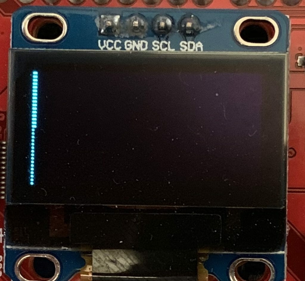
Don’t forget to setup the standard i/o by modifying stdio_user.h

#include "cycfg.h"
/* Must remain uncommented to use this utility */
#define IO_STDOUT_ENABLE
#define IO_STDIN_ENABLE
#define IO_STDOUT_UART      kitprog_HW
#define IO_STDIN_UART       kitprog_HW

When you run the program above you should get something like this:

One interesting question is HOW does the function SysTick_Handler get into the vector table?  Well if you run an eclipse search (type ctrl-h)

You will find it in an assembly language file called “startup_psoc6_01_cm4.s”

Double click on the file and you can see the Vector table.

__Vectors:
    .long    __StackTop            /* Top of Stack */
    .long    Reset_Handler         /* Reset Handler */
    .long    CY_NMI_HANLDER_ADDR   /* NMI Handler */
    .long    HardFault_Handler     /* Hard Fault Handler */
    .long    MemManage_Handler     /* MPU Fault Handler */
    .long    BusFault_Handler      /* Bus Fault Handler */
    .long    UsageFault_Handler    /* Usage Fault Handler */
    .long    0                     /* Reserved */
    .long    0                     /* Reserved */
    .long    0                     /* Reserved */
    .long    0                     /* Reserved */
    .long    SVC_Handler           /* SVCall Handler */
    .long    DebugMon_Handler      /* Debug Monitor Handler */
    .long    0                     /* Reserved */
    .long    PendSV_Handler        /* PendSV Handler */
    .long    SysTick_Handler       /* SysTick Handler */

But how do the _Vectors get into the right place?  Well? run the search again and you will find that the linker script (which Cypress created) for your project has the definition.

When you look in the linker script you can see that it is installed at the top of the flash

    {
        . = ALIGN(4);
        __Vectors = . ;
        KEEP(*(.vectors))
        . = ALIGN(4);
        __Vectors_End = .;
        __Vectors_Size = __Vectors_End - __Vectors;
        __end__ = .;

        . = ALIGN(4);
        *(.text*)

        KEEP(*(.init))
        KEEP(*(.fini))

        /* .ctors */
        *crtbegin.o(.ctors)
        *crtbegin?.o(.ctors)
        *(EXCLUDE_FILE(*crtend?.o *crtend.o) .ctors)
        *(SORT(.ctors.*))
        *(.ctors)

        /* .dtors */
        *crtbegin.o(.dtors)
        *crtbegin?.o(.dtors)
        *(EXCLUDE_FILE(*crtend?.o *crtend.o) .dtors)
        *(SORT(.dtors.*))
        *(.dtors)

        /* Read-only code (constants). */
        *(.rodata .rodata.* .constdata .constdata.* .conststring .conststring.*)

        KEEP(*(.eh_frame*))
    } > flash

And the CM4 flash is defined to start at 0x100002000

MEMORY
{
    /* The ram and flash regions control RAM and flash memory allocation for the CM4 core.
     * You can change the memory allocation by editing the 'ram' and 'flash' regions.
     * Note that 2 KB of RAM (at the end of the RAM section) are reserved for system use.
     * Using this memory region for other purposes will lead to unexpected behavior.
     * Your changes must be aligned with the corresponding memory regions for CM0+ core in 'xx_cm0plus.ld',
     * where 'xx' is the device group; for example, 'cy8c6xx7_cm0plus.ld'.
     */
    ram               (rwx)   : ORIGIN = 0x08002000, LENGTH = 0x45800
    flash             (rx)    : ORIGIN = 0x10002000, LENGTH = 0xFE000

    /* This is a 32K flash region used for EEPROM emulation. This region can also be used as the general purpose flash.
     * You can assign sections to this memory region for only one of the cores.
     * Note some middleware (e.g. BLE, Emulated EEPROM) can place their data into this memory region.
     * Therefore, repurposing this memory region will prevent such middleware from operation.
     */
    em_eeprom         (rx)    : ORIGIN = 0x14000000, LENGTH = 0x8000       /*  32 KB */

    /* The following regions define device specific memory regions and must not be changed. */
    sflash_user_data  (rx)    : ORIGIN = 0x16000800, LENGTH = 0x800        /* Supervisory flash: User data */
    sflash_nar        (rx)    : ORIGIN = 0x16001A00, LENGTH = 0x200        /* Supervisory flash: Normal Access Restrictions (NAR) */
    sflash_public_key (rx)    : ORIGIN = 0x16005A00, LENGTH = 0xC00        /* Supervisory flash: Public Key */
    sflash_toc_2      (rx)    : ORIGIN = 0x16007C00, LENGTH = 0x200        /* Supervisory flash: Table of Content # 2 */
    sflash_rtoc_2     (rx)    : ORIGIN = 0x16007E00, LENGTH = 0x200        /* Supervisory flash: Table of Content # 2 Copy */
    xip               (rx)    : ORIGIN = 0x18000000, LENGTH = 0x8000000    /* 128 MB */
    efuse             (r)     : ORIGIN = 0x90700000, LENGTH = 0x100000     /*   1 MB */
}

And when you look at the linker MAP file which is in your project Debug/BlinkyLED_mainapp.map you will see that the vectors end up in the right place.

.text           0x0000000010002000     0x5de4
                0x0000000010002000                . = ALIGN (0x4)
                0x0000000010002000                __Vectors = .

Cypress SysTick

Now if you happen to be reading the PDL documentation on Saturday afternoon you might notice that there is a section of the documentation called “SysTick”.  And when you click it you will find this:

And you might ask yourself “What the hell.. those aren’t CMSIS functions?”  Well in typical Cypress fashion we created an extension to SystTick.  It does two basic things

  1. Lets you pick different clock sources for the SysTick timer
  2. Lets you setup multiple callbacks to make it easier to trigger multiple functions in your system

For this example I modified the previous project by commenting out the CMSIS calls.  And I use the Cy_SysTick calls.

#include "cy_pdl.h"
#include "cycfg.h"
#include <stdio.h>

volatile uint32_t count;
cy_stc_scb_uart_context_t kitprog_context;

#if 0
void SysTick_Handler(void)
{
	count += 1;
}
#endif

void MyHander(void)
{
	count += 1;
}

int main(void)
{
	Cy_SCB_UART_Init(kitprog_HW,&kitprog_config,&kitprog_context);
	Cy_SCB_UART_Enable(kitprog_HW);
    /* Set up internal routing, pins, and clock-to-peripheral connections */
    init_cycfg_all();

    Cy_SysTick_Init ( CY_SYSTICK_CLOCK_SOURCE_CLK_CPU, 100000000/1000); // CPU Freq divide by 1000 makes MS
    Cy_SysTick_SetCallback(0,MyHander); // Slot 0
    Cy_SysTick_Enable();
    
//    SysTick_Config(SystemCoreClock/1000);

    /* enable interrupts */
    __enable_irq();

    for (;;)
    {
    		printf("Test count=%d\n",(int)count);
        Cy_GPIO_Inv(LED_RED_PORT, LED_RED_PIN); /* toggle the pin */
        Cy_SysLib_Delay(1000/*msec*/);
    }
}

When you look at this program you might ask where I got the “100000000/1000″…. and if Hassane is reading he will ask WHY DIDN’T YOU COMMENT IT.   The answer to the first question is that it is the CPU Frequency divided by 1000 to get a millisecond timer.

As to the second question… the answer is … “I just did” 🙂

There is probably some MACRO for those values… but I just don’t know what they are… and I suppose that I should go look… but…

And finally the “// slot 0”  means that it uses the first of 5 slots… in other words places where you can store a callback.

FreeRTOS usage of SysTick

The FreeRTOS by default uses the SysTick timer to cause the scheduler to run.  And it does this by using the CMSIS interface… well because everyone needs to do their own thing, it actually lets you define the function.  Here is a clip out of FreeRTOSConfig.h where it defines the actual function name as xPortSysTickHandler.

/* Definitions that map the FreeRTOS port interrupt handlers to their CMSIS
standard names - or at least those used in the unmodified vector table. */
#define vPortSVCHandler     SVC_Handler
#define xPortPendSVHandler  PendSV_Handler
#define xPortSysTickHandler SysTick_Handler

And when you look around (using find) you will find it in the file port.c.

void xPortSysTickHandler( void )
{
	/* The SysTick runs at the lowest interrupt priority, so when this interrupt
	executes all interrupts must be unmasked.  There is therefore no need to
	save and then restore the interrupt mask value as its value is already
	known. */
	portDISABLE_INTERRUPTS();
	{
		/* Increment the RTOS tick. */
		if( xTaskIncrementTick() != pdFALSE )
		{
			/* A context switch is required.  Context switching is performed in
			the PendSV interrupt.  Pend the PendSV interrupt. */
			portNVIC_INT_CTRL_REG = portNVIC_PENDSVSET_BIT;
		}
	}
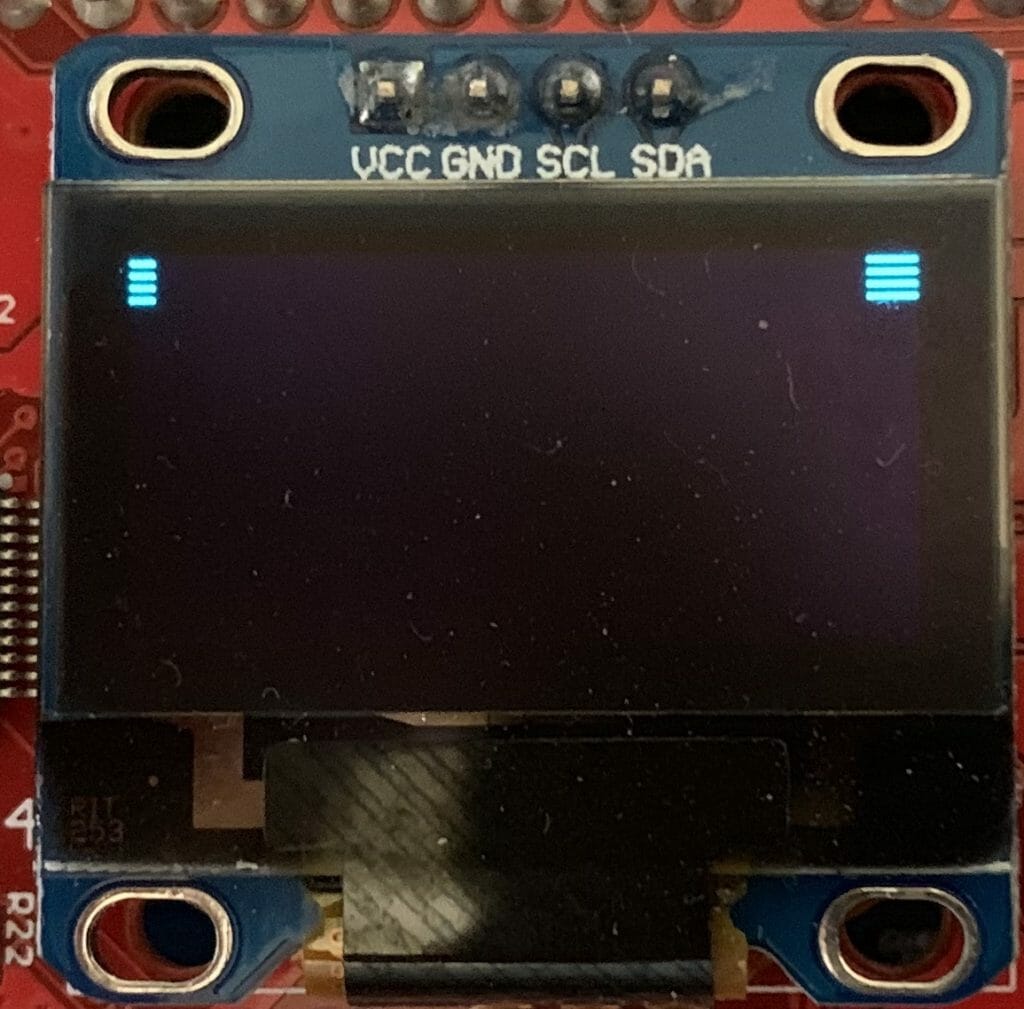
	portENABLE_INTERRUPTS();
}

And if you look in vTaskStartScheduler you will find that it calls the function vPortSetupTimerInterrupt where it sets up interrupt manually.

/*
 * Setup the systick timer to generate the tick interrupts at the required
 * frequency.
 */
__attribute__(( weak )) void vPortSetupTimerInterrupt( void )
{
	/* Calculate the constants required to configure the tick interrupt. */
	#if( configUSE_TICKLESS_IDLE == 1 )
	{
		ulTimerCountsForOneTick = ( configSYSTICK_CLOCK_HZ / configTICK_RATE_HZ );
		xMaximumPossibleSuppressedTicks = portMAX_24_BIT_NUMBER / ulTimerCountsForOneTick;
		ulStoppedTimerCompensation = portMISSED_COUNTS_FACTOR / ( configCPU_CLOCK_HZ / configSYSTICK_CLOCK_HZ );
	}
	#endif /* configUSE_TICKLESS_IDLE */

	/* Stop and clear the SysTick. */
	portNVIC_SYSTICK_CTRL_REG = 0UL;
	portNVIC_SYSTICK_CURRENT_VALUE_REG = 0UL;

	/* Configure SysTick to interrupt at the requested rate. */
	portNVIC_SYSTICK_LOAD_REG = ( configSYSTICK_CLOCK_HZ / configTICK_RATE_HZ ) - 1UL;
	portNVIC_SYSTICK_CTRL_REG = ( portNVIC_SYSTICK_CLK_BIT | portNVIC_SYSTICK_INT_BIT | portNVIC_SYSTICK_ENABLE_BIT );
}

And what is really cool is that when you look in FreeRTOSConfig.h you can see that it uses the CMSIS macro “SystemCoreClock” and that it is configured to have a 1MS callback.

#define configCPU_CLOCK_HZ                      SystemCoreClock
#define configTICK_RATE_HZ                      1000u

So, why did I look at all of that?  Well simple, each time that the SysTick interrupt is called, the FreeRTOS adds 1 to a count…. which you can get access to by calling “xTaskGetTickCount”.  Nice.

I think that is enough background… so let’s:

Make a New Project

I want to start by creating a copy of the project from the previous article (so that alls yall can see the progression of code changes).  In the previous article I walked you step-by-step through creating and copying a project.  Here is a summary of the step you need to take.  If you want to see the details please look at the last article.

  1. Make a new project
  2. Copy design.modus
  3. Add the middleware (FreeRTOS, Segger Core OS NoTouch & Soft FP,Segger BitPlains, Retarget I/O)
  4. Copy all of the files from the source directory
  5. Update the Include paths with the “eInk Library” and “emWin_Config”

After making all of these changes I will have a project in my workspace called “EHKEinkTiming”.  I would recommend before you go further that you build and program to make sure that everything is still working.

Measure the SPI Speed Increase

All of the action to dump the frame buffer onto the EINK display happens in the function UpdateDisplay in the file eInkTask.c.  In the code below you can see that I ask FreeRTOS what the count is before I dump the display, then what the count is after it is done.

void UpdateDisplay(cy_eink_update_t updateMethod, bool powerCycle)
{
    /* Copy the EmWin display buffer to imageBuffer*/
    LCD_CopyDisplayBuffer(imageBuffer, CY_EINK_FRAME_SIZE);

    uint32_t startCount = xTaskGetTickCount();
    /* Update the EInk display */
    Cy_EINK_ShowFrame(imageBufferCache, imageBuffer, updateMethod, powerCycle);
    uint32_t endCount = xTaskGetTickCount();
    printf("Update Display Time = %d\n",(int)(endCount - startCount));

    /* Copy the EmWin display buffer to the imageBuffer cache*/
    LCD_CopyDisplayBuffer(imageBufferCache, CY_EINK_FRAME_SIZE);
}

When I run the updated program I find that it takes about 1.7 seconds to update the screen.

Then I go back and modify the original program (before the SPI fixes) to see how long it takes…

And yes if you can do math, which I’m sure everyone who has read this far can, you will notice that I only sped things up by 65 Milliseconds… which means you need to call bullshit on my original declaration that it was noticeably faster.  Oh well at least I learned a bunch about the clock system.

Remove the HW timer & Update the EINK Driver

OK now that we have the hang of SysTick, it is clear that we don’t need the hardware timer that we put into the first project, so let’s get it out of there.  Start by running design.modus and removing the timer.  Just click the checkbox on “TCPWM[1]…” to turn it off.  Then press save.

If you hit compile you will find a whole bunch of errors… but they are all in four functions inside of cy_eink_psoc_interface.c.   Specifically

  • Cy_EINK_TimerInit
  • Cy_EINK_GetTimeTick
  • Cy_EINK_TimerStop

To fix them Ill first create a global static variable called “timerCount”

static uint32_t timerCount;

Then update Cy_EINK_TimerInit to just store the current FreeRTOS timer value in my new global variable.

void Cy_EINK_TimerInit(void)
{   
	timerCount = xTaskGetTickCount();
}

Next update Cy_EINK_GetTimeTick to return the number of ticks since the timer was initialized.

uint32_t Cy_EINK_GetTimeTick(void)
{
	    /* Return the current value of time tick */
    return(xTaskGetTickCount()-timerCount);
}

Finally, make the TimerStop function do… well… nothing.

void Cy_EINK_TimerStop(void)
{
}

When I build and program… my project is off to the races without the hardware timer.

In the next article Ill have a look at the EINK datasheet and driver to look into how it works.

CY8CKIT-028-EPD and Modus Toolbox 1.1

Summary

One of my very influential readers is working on a project where he wants to use the CY8CKIT-028-EPD.  But, he wants to use Modus Toolbox 1.1 instead of PSoC Creator and he observed, correctly, that Cypress doesn’t have a MTB code example project for the CY8CKIT-028-EPD.  I knew that we had a working code example in PSoC Creator (CE223727), so I decided to do a port to MTB1.1.  This turned out to be a bit of an adventure which required me to dig out a logic analyzer to solve self inflicted problems.  Here is a picture I took while sorting it out.

There are a few things in the PSoC Creator example code which I didn’t really like, so, for the final solution, I would like it to be

  • In Modus Toolbox 1.1
  • Using FreeRTOS
  • Using the Segger emWin graphics library
  • Getting the best response time
  • Using DMA to drive the display

For this article I will go through these steps:

  1. Build CE223727 EmWin_Eink_Display in PSoC Creator
  2. Explain the PSoC Creator Project
  3. Create a new MTB Project & add the FreeRTOS, Segger emWin and stdio middleware
  4. Configure the device for the correct pins, clocks and peripherals
  5. Setup FreeRTOS and Standard I/O
  6. Copy the driver files into the MTB project from the PSoC Creator workspace
  7. Port the drivers and eInkTask to work in MTB
  8. Program and Test
  9. (Part 2) Update the driver to remove the hardware timer
  10. (Part 2) Update the example to remove polled switch and use a semaphore
  11. (Part 2) Update the driver to use DMA
  12. (Part 2) Explain how the EINK EPD Display Works

If you lack patience and you just want a working project, you can download it from the IoT Expert GitHub site. git@github.com:iotexpert/eink-emwin-mtb1-1.git

First build CE223727 EmWin_Eink_Display in PSoC Creator

Start by finding the code example project for the Eink Display.  In PSoC Creator on the File->Code Example menu you will be able to pick out the code example.

There are a bunch of code examples, so the easiest way to find them is the filter based on “emwin”.  I did this because I knew we had used the Segger emWin Graphics library.  Notice in the picture below there are two emWin examples.  One with a “world” beside it and one without.  The world symbol means that it is on the internet and you will need to download it.  You can do that by clicking the world button.  Probably, you will find that your CE223727 EmWin_EInk_Display will have a world beside it and you will need to download it before you can make the project.

Once you click create project it will ask you about the project.  Just click “next”

Then give your project (and workspace) a name.  I called the workspace “EPDExample” and the project “CE22….”

After all of that is done you will have a schematic (and all of the other stuff required for the project).

When you click the program button it will ask you which MCU target to program (pick either, it doesnt matter)

After a while, your console window should look like this.

And you development kit should do its thing.

Explain the PSoC Creator Project

Now, lets have a look at the project.  Starting on the upper left hand part of the schematic you find that the interface to the EPD is via a SPI.  The SPI slave select is controlled with the Pervasive driver firmware rather than letting the SPI block directly control it.

The SPI is configured to be 16 megabits per second with CPHA=0 and CPOL=0.

I didn’t notice this at first, but in the picture above you can see that the actual speed of the SPI is 8.33 mbs.  That isn’t 16mbs for sure.  But why the gap?  The first thing to know is that in order for the SPI block to work correctly the input clock must be set at the desired datarate times the oversample.  What is oversample?  That is a scheme to get rid of glitchy-ness in the input signal.  In this case it will take 6 input samples to determine if the input is a 1 or a 0.  (median filter I think).  With this configuration the input clock to the SCB needs to be 16mbs * 6 = 96mhz.

But what is the input clock frequency?  If you click on the dwr->clocks you will see this screen which shows that the input clock is 50Mhz (the last line highlighted in blue).  Further more you can see that the source clock for the SCB is “Clk_Peri”.  When you divide 50mhz source clock rate by 6 oversample you will find that the actual bitrate is 8.33kbs.

But where does the 50mhz come from?  Well, the clock system is driven by the “IMO”.  IMO stands for internal main oscillator and it is a trimmed RC oscillator built into the chip. (thanks Tim).  This oscillator runs into an FLL which up converts it to 100MHz.

That signal is then run into the “Clk_Peri” divider which divides it by two to yield a clock of 50MHz.  Which is not all that close to 96MHz… and means that our SPI runs at the wrong speed.

But what does the EPD driver chip actually want?  You can find the documentation for this EPD on the Pervasive website.  That web page also has a link to the Product Specification 2.7″ TFT EPD Panel (E2271CS021) Rev.01 as well as the driver chip COG Driver Interface Timing for small size G2 V231

When you look in the timing document you will find that the actual chip can take up to a 20Mhz input clock.  This means that our code example actually updates the screen at 42% (8.33/20) of what it could.  That gives us a chance to make things faster… which I will do after the port to MTB.

The next sectin of the schematic has a TCPWM that is configured as a timer.  This has an input clock of 2kHz.


And is setup to divide by 2 which will yield a counter that updates every 1ms.  The author of this code example used the TCPWM to time operations inside of the driver (which I will also replace with something better)

Lastly there are some GPIOs that control various control pins on the display.  I don’t really know what all of the pins do, but will sort it out in the next article.

And all of the pins are assigned like this:

Create a new MTB project & Add the Middleware

It is time to start the project in MTB.  Start up Modus Toolbox 1.1 and select File->New->ModusToobox IDE Application    

Then select the CY8CKIT-062-BLE Development Kit.  This kit comes with the CY8CKIT-028-EPD EINK Shield that you can see in the pictures above.

I decide to call my project “EHKEink” and I derive my project from the “EmptyPSoC6App” template.

Once that is done, Let it rip.

And you should end up with a screen that looks like this. On the left in the workspace explorer you see the main app project.  In the middle you see the readme file which explains how this project is configured.

The next step is to add the “Middleware” that we need to make this project work.  You can do this by clicking the select Middleware button from the ModusToolbox quick panel.

For this project we need

  • FreeRTOS
  • Retarget I/O
  • Segger emWin Core, OS, no Touch, Soft FP
  • Segger emWin display driver BitPlains

The middleware selector will bring in all of the drivers you selected into your project.  You can see that it also adds the FreeRTOS configuration file “FreeRTOSConfig.h” as well as “stdio_user.c” etc.  These files endup in the source folder and are for you to edit.

While I was working on this, I found a bug in the emWin middleware, specifically the the configuration files for BitPlains get included twice.  To fix this you need to change the project properties and remove the path to “..components/psoc6mw/emWin/code/drivers/BitPlains/config”.  To do this, select the project in the workspace explorer then right click and select properties.

Then select “C/C++ General –> Paths and Symbols”.  Select the “…BitPlains/config” path and click “Delete”

Configure the device in MTB

Modus Toolbox does not have a “schematic” or a “dwr” like PSoC Creator.  In order to achieve the same functionality we built the “Configurator”.  This tool will let you setup all of the peripherals in your project.  To run it select “Configure Device” in the MTB Quick Panel.

Remember from the PSoC Creator Schematic we need to have:

  • A bunch of pins
  • A SPI
  • A Timer
  • Plus I want a UART to connect to standard I/O.

First, click on the “Pins” tab.  This lets you set all of the configuration information for each of the pins on the chip.  I will go one by one enabling the pins and setting them as digital inputs or output.  I am going to give all of the pins that exact same names that they had in the PSoC Creator Project because I know the author of that project used PDL.  When you give a pin a name in the configurator it will generate #defines or c structures based on the name.  This will make the source code the original PSoC Creator author wrote almost exactly compatible with MTB.

Here is an example of the first output pin which is P0[2] and is named CY_EINK_DispIoEn.  For the output pins you need to do four things.

  1. Enable the checkbox next to the pin name. (in this case P0[2])
  2. Give the pin a name (CY_EINK_DispIoEn)
  3. Set the drive mode (Strong Drive, Input buffer off)
  4. Set the initial state of the pin (High (1))

Now, you need to go one by one turning on all of the output pins (Im not showing you screen shots of all of them)

There are two input pins for this project SW2 P0[4] and CY_EINK_DispBusy P5[3].  For these pins I will:

  1. Enable the pin checkbox
  2. Give the pin a name (in this case SW2)
  3. Resistive Pull-Up, Input buffer on.  Note for P5[3] the pullup resistor is not needed

Now that the digital pins are configured, you can setup the STDIO Uart.  This will be used to send debugging messages to the console Uart which is attached to your computer via a USB<->UART bridge in KitProg 3.

Start by enabling SCB5 and giving it the name “UART”.  Make sure that the baud rate is set to 115200 and the rest to 8n1

Scroll down the window and pick out the RX and TX Pins plus the clock (any of the 8-bit clock dividers will do.  In this case I chose Divider 0)

Now, you need to setup the SPI.  To do this turn on SCB 6, set it to SPI, give it the name “CY_EINK_SPIM”, set it to “Master”, fix the data rate to 1000

Then scroll down to the “Connections” section and assign the pins

The last bit of hardware we need is a timer with a 1000kHz input clock, in other words a millisecond timer.  To do this start by enabling TCPWM[1] 16-bit counter.  Call it “CY_EINK_Timer” which was the same name as the PSoC Creator project.  Then setup

  • As a “Timer Counter”.
  • One shot
  • Up count
  • Period is 65535 (aka the max)
  • And pick “Clock signal” as 16 bit Divider

Given that we want it to count milliseconds and the input has a 128 bit pre-divider… we need for the input clock to be setup to 128khz.  Click on “Peripheral clocks” then select “16 Bit Divider 0”.  Notice that the input frequency is 72Mhz and we need 128Khz… to get this a divider of 562 is required.  72mhz/128khz = 562

Setup FreeRTOS and Standard I/O

The next step is to setup the “plumbing”.  In this projet we are using FreeRTOS and Standard I/O. To configure FreeRTOS just edit the “FreeRTOSConfig.h” and remove the “warning”

#warning This is a template. Modify it according to your project and remove this line. 

Enable mutexes on line 57

#define configUSE_MUTEXES                       1

Make the heap bigger on line 70

#define configTOTAL_HEAP_SIZE                   1024*48

Change the memory scheme to 4 on line 194

#define configHEAP_ALLOCATION_SCHEME                (HEAP_ALLOCATION_TYPE4)

To enable the UART to be used for Standard I/O, edit “stdio_user.h” and add the includes for “cycfg.h”.  Then update the output and input Uart to be “UART_HW” (which is the name you gave it in the configurator)

#include "cycfg.h"
/* Must remain uncommented to use this utility */
#define IO_STDOUT_ENABLE
#define IO_STDIN_ENABLE
#define IO_STDOUT_UART      UART_HW
#define IO_STDIN_UART       UART_HW

Now make a few edits to main.c to

  • Add includes for the configuration, rtos and standard i/o
  • Create a context for the UART
  • Create a blinking LED Task
  • In main start the UART and start the blinking LED task.
#include "cy_device_headers.h"
#include "cycfg.h"
#include "FreeRTOS.h"
#include "task.h"
#include <stdio.h>

cy_stc_scb_uart_context_t UART_context;

void blinkTask(void *arg)
{
	(void)arg;

    for(;;)
    {
    		vTaskDelay(500);
    		Cy_GPIO_Inv(LED_RED_PORT,LED_RED_PIN);
    		printf("blink\n");
    }
}
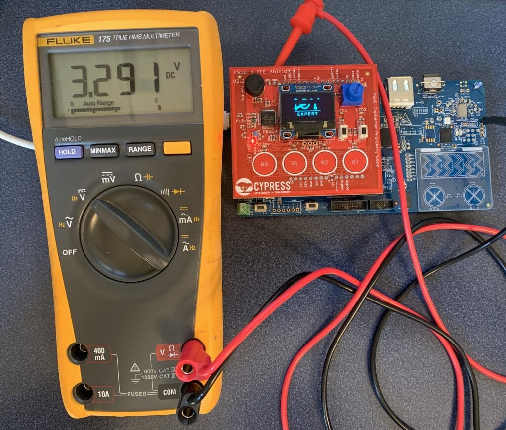
int main(void)
{
    init_cycfg_all();
    __enable_irq();

    Cy_SCB_UART_Init(UART_HW,&UART_config,&UART_context);
	Cy_SCB_UART_Enable(UART_HW);

  	xTaskCreate( blinkTask,"blinkTask", configMINIMAL_STACK_SIZE,  0,  1, 0  );
  	vTaskStartScheduler();
  	while(1);// Will never get here
}
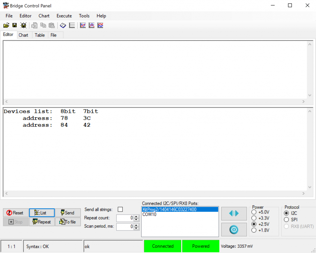
As I edited the code I notice that it can’t find “LED_RED” which made me realize that I forgot to add the LED_RED attached to P0[3] in the configuration.  So, I go back and update P0[3] to be LED_RED as strong drive digital output.

Finally just to make sure that it is all working lets program the kit.  When I press “EHKEink Program” form the quickpanel…

I get this message in the console.

But how can that be?  I have my kit plugged in?  In order to program your kit using Modus you need “KitProg3”.  PSoC Creator can program you kit with KitProg3 only if it is in the CMSIS-DAP HID mode.  To switch you development kit to KitProg3, you can use the program “fw-loader” which comes with MTB.  You can see what firmware you have by running “fw-loader –device-list”.  To change to KitProg 2 run “fw-loader –update-kp2” and to update to KitProg3 run “fw-loader –update-kp3”

Now when i program I get both the LED blinking and the console printing blink.

Copy the files into the MTB project

Next, I want to bring over the drivers from the PSoC Creator project.  They reside in folder called “eInk Library” inside of the PSoC Creator project.  You can copy them by navigating to the PSoC Creator workspace, then typing ctrl-c in the File Explorer, then clicking the “Source” directory in your Eclipse WorkSpace explorer and typing ctrl-v

You will also need the four files “GUIConf.c”, “GUIConf.h”, “LCDConf.h” and “LCDConf.c”.  Copy and paste them into the emWin_config directory.

For this project I am going to use the code that existed in “main.c” from the original PSoC Creator project.  But I want it to be a task (and a few other changes).  To facilitate things, I will copy it as well. Then rename it to eInkTask.c.  And finally, the file “Cypress Logo Full Color_png1bpp.c” needs to be copied as well.

After all of those copies you should have your project looking something like this:

Port the Drivers and eInkTask

Now we need to fix all of the driver code.  Big picture you will need to take the following actions.

  • Update the Project settings to include the new folders (emWin_config and emWin Library)
  • Replace the PSoC Creator #include <project.h> with MTB #include “cycfg.h”
  • Update the files to have #include “FreeRTOS.h” and “task.h” where appropriate
  • Replace all of the CyDelay’s with vTaskDelays
  • Fix the old PSoC Creator component calls for the timer with PDL calls

First go to the project settings (remember, click on the project then select properties).  Then pick “C/C++ Build Settings” then “GNU ARM Cross C Compiler” and “includes”  Press the little green “+” to add the new directories

You can select both directories at once.

Next edit  eInkTask.c

Update #include “project.h” to be #include “cycfg.h” on line 59.  Add “FreeRTOS.h” and “task.h” to the includes.

#include "cycfg.h"
#include "GUI.h"
#include "pervasive_eink_hardware_driver.h"
#include "cy_eink_library.h"
#include "LCDConf.h"
#include "FreeRTOS.h"
#include "task.h"
#include <stdio.h>

Find and replace “CyDelay” with “vTaskDelay”

Update the PSoC Creator component call  _Read with the pdl calls Cy_GPIO_Read on line 661

void WaitforSwitchPressAndRelease(void)
{
    /* Wait for SW2 to be pressed */
    while(Cy_GPIO_Read(SW2_PORT,SW2_PIN) != 0);
    
    /* Wait for SW2 to be released */
    while(Cy_GPIO_Read(SW2_PORT,SW2_PIN) == 0);
}
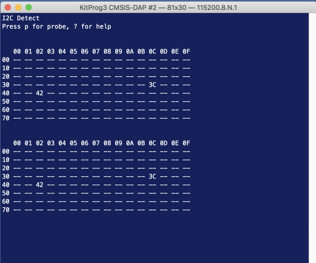
Update the “int main(void)” to be “void eInkTask(void *arg)” on line 687

void eInkTask(void *arg)
{
	(void)arg;

Remove ” __enable_irq(); /* Enable global interrupts. */” from the old main on line 695.

In the file cy_eink_psoc_interface.h

Update the #include <project.h> to be #include “cycfg.h” on line 59.

In the file cy_eink_psoc_interface.c

Create a context for the SPIM by adding on line 58:

cy_stc_scb_spi_context_t CY_EINK_SPIM_context;

The three timer functions in this file use the old PSoC Creator component timer interface APIs rather than the PDL interface.  So you will need to change Cy_EINK_TimerInit, Cy_EINK_GetTimeTick and Cy_EINK_TimerStop to use PDL.

Here is Cy_EINK_TimerInit

void Cy_EINK_TimerInit(void)
{   
    /* Clear the counter value and the counter variable */
    //CY_EINK_Timer_SetCounter(0);

    Cy_TCPWM_Counter_Init (CY_EINK_Timer_HW, CY_EINK_Timer_NUM, &CY_EINK_Timer_config);
    Cy_TCPWM_Counter_SetCounter	(	CY_EINK_Timer_HW, CY_EINK_Timer_NUM,0);
    
    Cy_TCPWM_Enable_Multiple(	CY_EINK_Timer_HW,CY_EINK_Timer_MASK);
    /* Initialize the Timer */
    //CY_EINK_Timer_Start();
    Cy_TCPWM_TriggerStart	(	CY_EINK_Timer_HW,CY_EINK_Timer_MASK);
}

And Cy_EINK_GetTimeTick

uint32_t Cy_EINK_GetTimeTick(void)
{
    /* Variable used to store the time tick */
    uint32_t timingCount;
    
    /* Read the current time tick from the E-INK Timer */
    //timingCount = CY_EINK_Timer_GetCounter();
    timingCount = Cy_TCPWM_Counter_GetCounter	(CY_EINK_Timer_HW, CY_EINK_Timer_NUM);


    /* Return the current value of time tick */
    return(timingCount);
}

And Cy_EINK_TimerStop

void Cy_EINK_TimerStop(void)
{
    /* Stop the E-INK Timer */
    //CY_EINK_Timer_Disable();
	Cy_TCPWM_Counter_Disable(CY_EINK_Timer_HW, CY_EINK_Timer_NUM);

}

In  the file LCDConf.h change the include to stdint.h and make the type uint8_t instead of uint8

#include  <stdint.h>
    
void LCD_CopyDisplayBuffer(uint8_t * destination, int count);

In the file LCDConf.c remove the #include “syslib/cy_syslib.h” (I have no idea why it is/was there) and then add “#include <stdint.h>”  On line 219 change “uint8” to be “uint8_t”

void LCD_CopyDisplayBuffer(uint8_t * destination, int count)

In the file cy_eink_fonts.h change the “#include <project.h>” to be

#include <stdint.h>
#include <stdbool.h>

In main.c add an external reference to the eInkTask on line 36 (yes this is really ugly Alan)

extern void eInkTask(void *);

And start the eInkTask on line 58.  Notice that I put in 10K for the stacksize… but I dont actually know how much it takes.

  	xTaskCreate( eInkTask,"eInkTask", 1024*10,  0,  1, 0  );

Program & Test the MTB Project

When you program the development kit you should have

  1. A blinking RED LED
  2. The ability to scroll through a bunch of screens using the SW2 button.

Here is a picture

In the next article I will:

  1. Speed up the SPI
  2. Get rid of the hardware timer
  3. Explain more about the EINK.


Embedded Graphics: TFT Displays & Drivers

Summary

This article will take you through a high level overview of all of the parts of a TFT LCD display.  The vast majority of what I have read on the internet makes this whole issue massively complex.  I’m quite sure that this complexity problem is a real reflection of the serious design and manufacturing complexity in these displays and drivers.  That being said, to get a conceptual understanding is much simpler, and is the point of this article.

A significant amount of my learning about this subject came from a 195 page powerpoint presentation by Dr. Fang-Hsing Wang entitled “Flat Panel Display : Principle and Driving Circuit Design“.  He has graciously allowed me to reproduce a few of his images.  This dude knows way way more about these circuits than I do and I would encourage you to read his work.

This article has the following subsections:

  1. TFT Pixel
  2. TFT Pixel Schematic
  3. TFT Panels (Also known as TFT Glass)
  4. TFT Gate Drivers
  5. TFT Source Drivers
  6. Gamma
  7. Multiplexing Gate and Source Drivers

TFT Pixel

The fundamental element in a TFT display is the liquid crystal.  These elements have the property that the crystals will align from horizontal (which blocks the light) to vertical (which lets most of the light through) based on the electric field applied to them.  Basically, you shine light through the liquid crystal, which blocks some or all of the light, the remainder of the white light then goes through a color filter to make red, green, or blue. It works like this:

  1. You use an array of LEDs to shine white light from the back of the screen towards the front (your eyes) 
  2. Into a diffuser (to spread out the light and make it even)
  3. You control the orientation of the crystals using a voltage to apply an electric field to the crystals
  4. The white light from the back (often called the backlight) will shine through the liquid crystal elements.  The amount of light coming out will depend on the orientation of the crystals.
  5. The white light coming out of the crystal will then go into a red, green or blue color filter making it red, green or blue (RGB)
  6. The light from three RGB filters will combine in your eye into a color based on the amount of red, green and blue (purple in the case below)

This architecture means that every pixel in the display will require a red, green and blue element.  And, you will need to control the voltage on all of the elements (which will be quite a lot on a screen of any size)

Here is a nice cross section that I found on Innolux’s website.

Pixel Schematic

What does the schematic for one element in a pixel look like?  And where is the T(transistor) in the TFT?  The three letter acronym TFT stands for a thin film transistor that is physically on the top of the LCD matrix right next to each liquid crystal element.  Here is a schematic model for one element in the array.  C-LC represents the capacitance of the liquid crystal.  CS is a storage capacitor that is used to hold the electric field across the liquid crystal when the transistor is OFF.   To apply a voltage across the LC you just turn on the gate and apply the correct voltage to the column commonly known as the source.

You should notice that the “back” terminal of the two capacitors is called “VCOM” and is physically on the other side of the liquid crystal matrix from the TFT.  All of the liquid crystal backsides in the display are connected to the same VCOM.  A bit of painfulness in this system is that the CS capacitor leaks, which means that the LCD changes state which means that each pixel must be updated, properly called refreshed, on a regular basis.

TFT Panel

We know that each pixel has three three thin film transistors, three capacitors, three color filters (red, green and blue) and that we need to control the voltage on the source/drain of each transistor in order to cause the right amount of light to come through the liquid crystal.  How do we do that?  The first step is to arrange all of the pixels in a matrix.  Each row of matrix has all of the gates connected together.  And each column of the matrix has all of the sources tied together.  In order to address a specific pixel RGB element, you turn on the correct row and then apply a voltage to the correct column at the right time.

If you have been thinking about this system you might have done a little bit of math and figured out that you are going to need an absolute boatload of source and gate driver signals.  And you would be right!  For example, a 4.3″ screen with 480×272 will require 480x272x3 elements which are probably organized into 480 rows by 816 columns.  This would require a chip with at least 480+816=1296 pins, that is a lot.  It turns out that for small screens <=3.5″ there are chips with enough pins to do the job.  But, for larger screens, it requires multiple chips to do the job.  The “…” in the picture above shows the driver chips being cascaded.  The next thing to know is that “TFT Glass” usually has the driver chip(s) embedded into the screen at the edge (you can see that in the picture from Innolux above).

TFT Gate Drivers

You must put a quite high voltage source >20v and drain <-10V across the liquid crystal at the right time to get it to do its thing.  In order to pass that source voltage, the gate must be turned on at the right time to the right voltage, this is the purpose of the Gate Driver IC.  The gate driver is conceptually simple and Dr. Wang drew a nice picture on page 7 of his presentation.  You can see that it is basically a shift register, with one element per gate.  You shift in a “1” and then clock it through the entire shift register which will have the effect of applying a 1 to each gate.

However, a 3.3v logic 1 is not anywhere high enough to drive the gate so that it can pass the much higher source voltage.  So, you need to level shifter and a buffer to get the “right” voltage.   On page 15, Dr. Wang made a nice picture of this circuit as well.

It turns out that this picture is conceptually correct, but the exact implementation has “a lot going on”.  You can read about the next layer of circuit design in his presentation on pages 15-35.

TFT Source Drivers

In its most basic form, the TFT source driver is responsible for taking an 8-bit digital input value representing the value of an individual LCD element and turning it into a voltage, the driving the voltage.  Like this:

You could conceptually have one DAC per column in the panel.  But this would have at least two problems

  1. The DACs are big circuits and this would make for giant source driver chips
  2. You would need to “save” all of the digital values for an entire row so that when you turned on the row, you could turn on all of the DACs on at the same time.

You could conceptually also have one DAC for all of the columns, but this would have a bunch of problems including:

  1. The DAC would have to be strong enough to drive all of the columns
  2. You would need 3x the number of row drivers to effectively de-mux the column
  3. You would need 1 pin on the source driver per column in the panel (for an 800×600 lcd that would be 600×3 = 1800 pins)

In reality there is some compromise of chip size, number of pins and time that is made by multiplexing pins, columns and rows.  For example, many of the small screens appear to have 1 column driver for all of the reds, 1 driver for the blues and one for greens. 

What appears to happen in real life on bigger screens is some combination of column and row multiplexing.  In one display that I found there were 2x the number of rows which allows the columns to be multiplexed 2-1.  The display is 1024×600.  That requires 1024*3 RGBs in the column = 1536 pins.  This means that you need to double the number of gate drivers, resulting in 1200 pins in the row direction.  Here is a picture from their datasheet.

Gamma Correction

The last issue that I will address in TFT LCD drivers is called Gamma Correction or more simply Gamma.  Gamma is an intensity adjustment factor.  For any given digital intensity input, you will need a non-linear translation to a voltage output on the source.  For example a doubling of digital input (so that a pixel appears twice as bright) you will not double but instead will have some non-linear translation of the output voltage.

There appear to be a bunch of reason why you need Gamma Correction including at least:

  1. Your eye perceives light intensity in a non-linear way
  2. The LCD panel responds differently based on the input
  3. The intensity variance is dependent on the color

The good news is that this gamma correction is built into the display drivers.  From my reading, this is sometimes done with digital processing, and sometimes done with an analog circuit.  But in general, it appears to be tuned and programmed into the driver by the panel vendor for these smaller display.

In the next article I will write about TFT Controllers.

Embedded Graphics Index

Embedded Graphics
Embedded Graphics Overview
TFT Displays & Drivers
TFT Controllers
PSoC 6 + Segger EmWin + MCUFriend 2.4" TFT - Part 1
PSoC 6 + Segger EmWin + MCUFriend 2.4" TFT - Part 2
MCU Friend 3.5" Identification

MCU Friend 3.5 TFT Identification

Summary

I bought four MCU Friend 3.5″ TFT shields.  And, unfortunately, they have spiraled me into a deep, dark place trying to figure out how to use them.  The the documentation consists of a sticker on the antistatic bag, a picture of the shield with a list of 5 different possible LCD drivers, a pinout, and a block of code that supposedly represents the startup code.  The unfortunate part is that none of these have been exactly right – they all have errors.  This article is a description of the journey to figuring out how to use them.

This article has the following parts:

  1. MCU Friend 3.5″ Documentation
  2. MCU Friend 3.5″ Shields
  3. Using the MCUFRIEND_kbv Library
  4. Identify the LCD Driver with Register Reads
  5. A PSoC Program To Identify LCD Controllers
  6. Using the MCUFriend_kbv Startup Code
  7. Use the Web Startup
  8. Conclusion

MCU Friend 3.5″ Documentation

Here is a picture of the bag. (the QR code is a number “181024202132” which I thought might be a phone number but isn’t.  It also doesn’t match anything in google, so i’m not sure what it is.

This text on the website says:

Features:

  •   5inch TFT LCD Module, Resolution 480×320, Controller ili9481 ili9468, ili9488 hx8357, or r61581.
  •      Designed with a TF(Micro SD) card socket on the back of board so that you can conveniently insert a card.
  •      Support touch screen function.
  •      The test code is provided below.
  •      This kit requires certain professional knowledge and ability, make sure you know how to use it, please. We cannot provide any technical assistance.

Specifications:

Controller: ili9481 ili9468, ili9488 hx8357, or r61581

Resolution: 480×320

Voltage: 5V/3.3V

Package Include: 1 x LCD Module

The website also has this code which they claim is the startup code.  It is interesting that

  1. There are several lines are commented out
  2. It implies that you have a  SPI interface
  3. When you look at the commands some of them don’t exist in some of the controllers
write_SPI_commond(0xFF);
delay_nms(5);
write_SPI_commond(0xFF);
delay_nms(10);
write_SPI_commond(0xB0);
write_SPI_data(0x00);
write_SPI_commond(0xB3);
write_SPI_data(0x02);
write_SPI_data(0x00);
write_SPI_data(0x10);
write_SPI_commond(0xB4);
write_SPI_data(0x11);//0X10
write_SPI_commond(0xC0);
write_SPI_data(0x13);
write_SPI_data(0x3B);//
write_SPI_data(0x00);
write_SPI_data(0x01);
write_SPI_data(0x00);//NW
write_SPI_data(0x43);
write_SPI_commond(0xC1);
write_SPI_data(0x08);
write_SPI_data(0x15);//CLOCK
write_SPI_data(0x08);
write_SPI_commond(0xC4);
write_SPI_data(0x15);
write_SPI_data(0x03);
write_SPI_data(0x01);
write_SPI_commond(0xC6);
write_SPI_data(0x02);
write_SPI_commond(0xC8);
write_SPI_data(0x0c);
write_SPI_data(0x05);
write_SPI_data(0x0A);//0X12
write_SPI_data(0x6B);//0x7D
write_SPI_data(0x04);
write_SPI_data(0x06);//0x08
write_SPI_data(0x15);//0x0A
write_SPI_data(0x10);
write_SPI_data(0x00);
write_SPI_data(0x31);//0x23
write_SPI_data(0x10);
write_SPI_data(0x15);//0x0A
write_SPI_data(0x06);//0x08
write_SPI_data(0x64);//0x74
write_SPI_data(0x0D);//0x0B
write_SPI_data(0x0A);//0x12
write_SPI_data(0x05);//0x08
write_SPI_data(0x0C);//0x06
write_SPI_data(0x31);//0x23
write_SPI_data(0x00);
write_SPI_commond(0x35);
write_SPI_data(0x00);
//write_SPI_commond(0x36);
//write_SPI_data(0x00);
write_SPI_commond(0x0C);
write_SPI_data(0x66);
write_SPI_commond(0x3A);
write_SPI_data(0x66);
write_SPI_commond(0x44);
write_SPI_data(0x00);
write_SPI_data(0x01);
write_SPI_commond(0xD0);
write_SPI_data(0x07);
write_SPI_data(0x07);//VCI1
write_SPI_data(0x14);//VRH 0x1D
write_SPI_data(0xA2);//BT 0x06
write_SPI_commond(0xD1);
write_SPI_data(0x03);
write_SPI_data(0x5A);//VCM  0x5A
write_SPI_data(0x10);//VDV
write_SPI_commond(0xD2);
write_SPI_data(0x03);
write_SPI_data(0x04);//0x24
write_SPI_data(0x04);
write_SPI_commond(0x11);
delay_nms(150);
write_SPI_commond(0x2A);
write_SPI_data(0x00);
write_SPI_data(0x01);
write_SPI_data(0x3F);//320
write_SPI_commond(0x2B);
write_SPI_data(0x00);
write_SPI_data(0x01);
write_SPI_data(0xDF);//480
//write_SPI_commond(0xB4);
//write_SPI_data(0x00);
delay_nms(100);
write_SPI_commond(0x29);
delay_nms(30);
write_SPI_commond(0x2C);

It also has a picture which says the LCD has one of several different controllers (and after digging in I know for a fact that two of mine were made by Raydium and are not on the list)

And finally a table of pins.  Which is interesting as it lists 37 pins when the shield has no where near that number.  And it shows the shield as  16-bit interface which it isnt … and it shows some LEDs which aren’t there either.

MCU Friend 3.5″ Shields

I bought 4 different shields.  One came broken.  The other three are all different.  When you look at the boards there are two visibly different configurations


Using the MCUFRIEND_kbv Library

The first thing I did was try to use the MCUFRIEND_kbv library to see if the screens worked.  The first board identified as ID=0x9403 and did not work.  Apparently, the tool just spits out the ID if it doesn’t know it, which it did not.

One of the boards identified as ID=0x6814 worked perfectly, and one had a blue cast to all of the screens.  The crazy part is the two boards that identified as ID=0x6814 had different PCBs.  According to the comments in the MCUFRIEND_kbv.cpp ID=0x6814 is an RM68140 and ID=9403 is unknown.

Here is the one with the blue cast:

Here is the functional one:

Identify with Register Reads

Next, I started down the path of trying to figure out what the controllers were by using register reads.  David Prentice (the guy who wrote/maintains the MCU Friend_kbv Arduino library) has an absolute ton of responses on the Arduino forum trying to help people figure out what their shield is.  He asks them to post the register report from his example program LCD_ID_readnew which is included as an example in the library.

When you look at these LCD controllers they all have some variant of “Read ID” which responds with 1-6 bytes.  The basic idea of this program is to look at what bytes are returned to try to identify the controller.  Here is an example of what I got when I ran the LCD_ID_readnew program on my shields:

reg(0x0000) 00 00       ID: ILI9320, ILI9325, ILI9335, ...
reg(0x0004) 54 54 80 66 Manufacturer ID
reg(0x0009) 00 00 61 00 00           Status Register
reg(0x000A) 08 08 Get Powsr Mode
reg(0x000C) 66 66 Get Pixel Format
reg(0x0030) 00 00 00 01 DF  PTLAR
reg(0x0033) 00 00 00 01 E0 00 00        VSCRLDEF
reg(0x0061) 00 00 RDID1 HX8347-G
reg(0x0062) 00 00 RDID2 HX8347-G
reg(0x0063) 00 00 RDID3 HX8347-G
reg(0x0064) 00 00 RDID1 HX8347-A
reg(0x0065) 00 00 RDID2 HX8347-A
reg(0x0066) 00 00 RDID3 HX8347-A
reg(0x0067) 00 00 RDID Himax HX8347-A
reg(0x0070) 00 00 Panel Himax HX8347-A
reg(0x00A1) 00 00 00 00 00    RD_DDB SSD1963
reg(0x00B0) 00 00 RGB Interface Signal Control
reg(0x00B3) 00 00 11 00 00      Frame Memory
reg(0x00B4) 00 00 Frame Mode
reg(0x00B6) 02 02 02 3B 00      Display Control
reg(0x00B7) 06 06 Entry Mode Set
reg(0x00BF) FF FF 68 14 00 FF   ILI9481, HX8357-B
reg(0x00C0) 0E 0E 0E 00 00 00 00 00 00   Panel Control
reg(0x00C1) 04 04 00 00 Display Timing
reg(0x00C5) 00 00 Frame Rate
reg(0x00C8) 00 00 00 00 00 00 00 00 00 00 00 00 00      GAMMA
reg(0x00CC) 00 00 Panel Control
reg(0x00D0) 00 00 00 00 Power Control
reg(0x00D1) 00 00 00 00 VCOM Control
reg(0x00D2) 00 00 00 Power Normal
reg(0x00D3) 00 00 94 86    ILI9341, ILI9488
reg(0x00D4) 00 00 00 00    Novatek
reg(0x00DA) 54 54 RDID1
reg(0x00DB) 80 80 RDID2
reg(0x00DC) 66 66 RDID3
reg(0x00E0) 00 00 54 07 44 05 08 00 54 07 44 05 08 44 44 00     GAMMA-P
reg(0x00E1) 00 00 00 00 00 00 00 00 00 00 00 00 00 00 00 00     GAMMA-N
reg(0x00EF) 00 00 00 00 00 00 ILI9327
reg(0x00F2) 00 00 00 00 00 00 00 00 00 00 00 00 Adjust Control 2
reg(0x00F6) 00 00 00 00 Interface Control

The key thing to see in this output is the register 0x04 which says 54,80,66 which identifies this as a Raydium RM68140 LCD controller.  Here is a snapshot from the data sheet.

Unfortunately, the next thing to notice is that Register 0xBF has reg(0x00BF) FF FF 68 14 00 FF.  The unfortunate part is that this register is not documented in the data sheet beyond this one reference:

Presumably the “68 14” corresponds to a Raydium 68140, but who knows?  When I posted this on the Arduino forum, David Prentice responded (David does yeoman’s labor helping people and should be Thanked for all of his pro-bono work and putting up with a bunch of really bad questions)

After digging some more, I decided that it is super ugly out there, as you find that there are a significant number of LCD controllers that are clones, copies, pirated etc… and that they all present themselves differently.  And, in hindsight I think that this is the reason that my ILI9341 from the previous article doesnt quite work correctly.

A PSoC Program To Identify LCD Controllers

The next thing that I did was create a PSoC Program to read registers from the controllers to try to figure out what they were.  My original plan was to write a complete identification program, but I have largely decided that this is a waste of time (more on this later).  Here is the beginning of the project, it is called “Identify” in the workspace.

First, a function to reset the screen by toggling the reset line on the controller, then sending a command “0x01” which is commonly a software reset.   It turns out that I spent a bunch of time trying to figure out what was going on because I was not getting any responses from the controllers.  This was caused by not sending the software reset, which at least in two of the cases makes them unresponsive.

#define LCD_COMMAND (0)
#define LCD_DATA (1)

void lcdReset()
{
       /* Reset - High, Low (reset), High */
    Cy_GPIO_Set(LCD_RESET_N_0_PORT, LCD_RESET_N_0_NUM);
    CyDelay(200);
    Cy_GPIO_Clr(LCD_RESET_N_0_PORT, LCD_RESET_N_0_NUM);
    CyDelay(200);
    Cy_GPIO_Set(LCD_RESET_N_0_PORT, LCD_RESET_N_0_NUM);
    CyDelay(200);
   
    GraphicLCDIntf_1_Write8(LCD_COMMAND,0x01);
 
}

void regReadPrint(uint8_t reg,uint8_t *buff,uint16_t num)
{
    GraphicLCDIntf_1_Write8(LCD_COMMAND,reg);
    GraphicLCDIntf_1_ReadM8(LCD_DATA,buff,num);
    printf("%02X ",reg);
    for(int i=0;i<num;i++)
    {
        printf("0x%02X,",buff[i]);
    }
    printf("\r\n");
    
}

Then I built a command line interface that queries the typical registers:

int main(void)
{
    uint8_t buff[128];

    __enable_irq(); /* Enable global interrupts. */

    UART_Start();
    setvbuf( stdin, NULL, _IONBF, 0 );
    printf("Started\r\n");
    
    GraphicLCDIntf_1_Start();
    lcdReset();
    
    while(1)
    {
        char c;
        c=getchar();
        
        switch(c)
        {  
            case 'a':
                regReadPrint(0x04,buff,6);
                regReadPrint(0xA1,buff,6);
                regReadPrint(0xBF,buff,6);
                regReadPrint(0xDA,buff,1);
                regReadPrint(0xDB,buff,1);
                regReadPrint(0xDC,buff,1);
                regReadPrint(0xd3,buff,6);
            break;

When I ran this program on the three controllers here is what I got:

Screen 1:
04 0x00,0x00,0x94,0x03,0x00,0x00,
A1 0x00,0x00,0x00,0x00,0x00,0x00,
BF 0x00,0x00,0x00,0x00,0x00,0x00,
DA 0x00,
DB 0x94,
DC 0x03,
D3 0x00,0x00,0x94,0x03,0x00,0x00,

Screen 2: Raydium 68140 (arduino works)
04 0x54,0x54,0x80,0x66,0x00,0x00,
BF 0xFF,0xFF,0x68,0x14,0x00,0xFF,
DA 0x54,
DB 0x80,
DC 0x66,
D3 0x00,0x00,0x94,0x86,0x00,0x00,

Screen 3: Raydium 68140 (looks blue)
04 0x54,0x54,0x80,0x66,0x00,0x00,
BF 0xFF,0xF7,0x60,0x14,0x00,0xFF,
DA 0x54,
DB 0x80,
DC 0x66,
D3 0x00,0x00,0x94,0x86,0x00,0x00,

So, where does this leave me?

  1. I have no idea what Screen 1 is?  04 0x00,0x00,0x94,0x03,0x00,0x00,
  2. Two of them appear to be Raydium RM68140s
  3. The two Raydiums have different register values for 0xBF

And all of this is insane because most of these companies don’t appear to have coherent websites or generally available datasheets.  I suppose that it would help if I spoke and read Chinese.

Using the MCUFriend_kbv Startup Code

The next thing that I did was try out the startup code that MCUFriend_kbv generates.  I used the same technique from PSoC 6 + Segger EmWin + MCUFriend 2.4″ Part 1 and spit out the startup bytes.  Here they are:

0x1,0x0, 
0x28,0x0, 
0x3A,0x1,0x55, 
0x3A,0x1,0x55, 
0x11,0x0, 
0x29,0x0, 
0xB6,0x3,0x0,0x22,0x3B, 
0x36,0x1,0x8, 
0x2A,0x4,0x0,0x0,0x1,0x3F, 
0x2B,0x4,0x0,0x0,0x1,0xDF, 
0x33,0x6,0x0,0x0,0x1,0xE0,0x0,0x0, 
0x37,0x2,0x0,0x0, 
0x13,0x0, 
0x20,0x0, 

And this is what it looks like in my PSoC program:

static const uint8_t mcu35_init_sequence_kbv[]  = {
    0x1,0x0,                            // Software Reset
    0x28,0x0,                           // Display Off
    0x3A,0x1,0x55,                      // Pixel Format Set 565
    0x3A,0x1,0x55,                      // Pixel Format Set 565
    0x11,0x0,                           // Sleep Out
    0x29,0x0,                           // Display On
    0xB6,0x3,0x0,0x22,0x3B,             // Display Function Control
    0x36,0x1,0x8,                       // Memory Access Control
    0x2A,0x4,0x0,0x0,0x1,0x3F,          // Column Set Address 320
    0x2B,0x4,0x0,0x0,0x1,0xDF,          // Page Set Addres 480
    0x33,0x6,0x0,0x0,0x1,0xE0,0x0,0x0,  // Vertical Scrolling Definition
    0x37,0x2,0x0,0x0,                   // Vertical Scrolling Start Address
    0x13,0x0,                           // Normal Display On
    0x20,0x0,                           // Display Inversion Off
};

When I run this things look like this:

Screen 1: Looks good, just need to flip the x-axis

Screen 2: Looks good, just need to flip the y-axis

Screen 3: Not good… not exactly sure how to fix.

Use the Web Startup

Well, things still aren’t quite right, so for some strange reason, I keep going and try to use the startup code from the web.  In order to make it work I translate

  • delay_nms –> CyDelay
  • write_SPI_commond –> GraphicLCDIntf_1_Write8_A0
  • write_SPI_data –> GraphicLCDIntf_1_Write8_A1

Here is the updated code:

static void _InitController35Web()
{
    GraphicLCDIntf_1_Write8_A0(0xFF);
    GraphicLCDIntf_1_Write8_A0(0xFF);
    CyDelay(5);
    GraphicLCDIntf_1_Write8_A0(0xFF);
    GraphicLCDIntf_1_Write8_A0(0xFF);
    GraphicLCDIntf_1_Write8_A0(0xFF);
    GraphicLCDIntf_1_Write8_A0(0xFF);
    CyDelay(10);
    //0xB0,0x01,0x00,
    GraphicLCDIntf_1_Write8_A0(0xB0); //0
    GraphicLCDIntf_1_Write8_A1(0x00);
    
    //0xB3,0x04,0x02,0x00,0x00,0x10,
    GraphicLCDIntf_1_Write8_A0(0xB3); //1
    GraphicLCDIntf_1_Write8_A1(0x02);
    GraphicLCDIntf_1_Write8_A1(0x00);
    GraphicLCDIntf_1_Write8_A1(0x00);
    GraphicLCDIntf_1_Write8_A1(0x10);
    
    //0xB4,0x01,0x11,
    GraphicLCDIntf_1_Write8_A0(0xB4); // 2
    GraphicLCDIntf_1_Write8_A1(0x11);//0X10

    // 0xC0,0x08,0x13,0x3B,0x00,0x00,0x00,0x01,0x00,0x43,
    GraphicLCDIntf_1_Write8_A0(0xC0);
    GraphicLCDIntf_1_Write8_A1(0x13);
    GraphicLCDIntf_1_Write8_A1(0x3B);//
    GraphicLCDIntf_1_Write8_A1(0x00);
    GraphicLCDIntf_1_Write8_A1(0x00);
    GraphicLCDIntf_1_Write8_A1(0x00);
    GraphicLCDIntf_1_Write8_A1(0x01);
    GraphicLCDIntf_1_Write8_A1(0x00);//NW
    GraphicLCDIntf_1_Write8_A1(0x43);

    // 0xC1,0x04,0x08,0x15,0x08,0x08,
    GraphicLCDIntf_1_Write8_A0(0xC1);
    GraphicLCDIntf_1_Write8_A1(0x08);
    GraphicLCDIntf_1_Write8_A1(0x15);//CLOCK
    GraphicLCDIntf_1_Write8_A1(0x08);
    GraphicLCDIntf_1_Write8_A1(0x08);

    // 0xC4,0x04,0x15,0x03,0x03,0x01
    GraphicLCDIntf_1_Write8_A0(0xC4);
    GraphicLCDIntf_1_Write8_A1(0x15);
    GraphicLCDIntf_1_Write8_A1(0x03);
    GraphicLCDIntf_1_Write8_A1(0x03);
    GraphicLCDIntf_1_Write8_A1(0x01);

    // 0xC6,0x01,0x02
    GraphicLCDIntf_1_Write8_A0(0xC6);
    GraphicLCDIntf_1_Write8_A1(0x02);

    // 0xC8,0x15,0x0C,0x05,0x0A,0x6B,0x04,0x06,0x15,0x10,0x00,0x31,0x10,0x15,0x06,0x64,0x0D,0x0A,0x05,0x0C,0x31,0x00
    GraphicLCDIntf_1_Write8_A0(0xC8);
    GraphicLCDIntf_1_Write8_A1(0x0c);
    GraphicLCDIntf_1_Write8_A1(0x05);
    GraphicLCDIntf_1_Write8_A1(0x0A);//0X12
    GraphicLCDIntf_1_Write8_A1(0x6B);//0x7D
    GraphicLCDIntf_1_Write8_A1(0x04);
    GraphicLCDIntf_1_Write8_A1(0x06);//0x08
    GraphicLCDIntf_1_Write8_A1(0x15);//0x0A
    GraphicLCDIntf_1_Write8_A1(0x10);
    GraphicLCDIntf_1_Write8_A1(0x00);
    GraphicLCDIntf_1_Write8_A1(0x31);//0x23
    GraphicLCDIntf_1_Write8_A1(0x10);
    GraphicLCDIntf_1_Write8_A1(0x15);//0x0A
    GraphicLCDIntf_1_Write8_A1(0x06);//0x08
    GraphicLCDIntf_1_Write8_A1(0x64);//0x74
    GraphicLCDIntf_1_Write8_A1(0x0D);//0x0B
    GraphicLCDIntf_1_Write8_A1(0x0A);//0x12
    GraphicLCDIntf_1_Write8_A1(0x05);//0x08
    GraphicLCDIntf_1_Write8_A1(0x0C);//0x06
    GraphicLCDIntf_1_Write8_A1(0x31);//0x23
    GraphicLCDIntf_1_Write8_A1(0x00);

    // 0x35,0x01,0x00
    GraphicLCDIntf_1_Write8_A0(0x35);
    GraphicLCDIntf_1_Write8_A1(0x00);
    //GraphicLCDIntf_1_Write8_A0(0x36);
    //GraphicLCDIntf_1_Write8_A1(0x00);

    // 0x0C,0x01,x066
    GraphicLCDIntf_1_Write8_A0(0x0C);
    GraphicLCDIntf_1_Write8_A1(0x66);

    //0x3A,0x01,0x55
    GraphicLCDIntf_1_Write8_A0(0x3A);
    GraphicLCDIntf_1_Write8_A1(0x55); // ARH changed to 565
    //GraphicLCDIntf_1_Write8_A1(0x66);

    // 0x44,0x02,0x00,0x01
    GraphicLCDIntf_1_Write8_A0(0x44);
    GraphicLCDIntf_1_Write8_A1(0x00);
    GraphicLCDIntf_1_Write8_A1(0x01);

    // 0xD0,0x04,0x07,0x07,0x14,0xA2,
    GraphicLCDIntf_1_Write8_A0(0xD0);
    GraphicLCDIntf_1_Write8_A1(0x07);
    GraphicLCDIntf_1_Write8_A1(0x07);//VCI1
    GraphicLCDIntf_1_Write8_A1(0x14);//VRH 0x1D
    GraphicLCDIntf_1_Write8_A1(0xA2);//BT 0x06


    // 0xD1,0x03,0x03,0x5A,0x10 
    GraphicLCDIntf_1_Write8_A0(0xD1);
    GraphicLCDIntf_1_Write8_A1(0x03);
    GraphicLCDIntf_1_Write8_A1(0x5A);//VCM  0x5A
    GraphicLCDIntf_1_Write8_A1(0x10);//VDV

    // 0xD2,0x03,0x03,0x04,0x04,
    GraphicLCDIntf_1_Write8_A0(0xD2);
    GraphicLCDIntf_1_Write8_A1(0x03);
    GraphicLCDIntf_1_Write8_A1(0x04);//0x24
    GraphicLCDIntf_1_Write8_A1(0x04);

    // 0x11,0x00,
    GraphicLCDIntf_1_Write8_A0(0x11);
    CyDelay(150);


    // 0x2A,0x04,0x00,0x00,0x01,0x3F
    GraphicLCDIntf_1_Write8_A0(0x2A);
    GraphicLCDIntf_1_Write8_A1(0x00);
    GraphicLCDIntf_1_Write8_A1(0x00);
    GraphicLCDIntf_1_Write8_A1(0x01);
    GraphicLCDIntf_1_Write8_A1(0x3F);//320


    // 0x2B,0x04,0x00,0x00,0x01,0xDF
    GraphicLCDIntf_1_Write8_A0(0x2B);
    GraphicLCDIntf_1_Write8_A1(0x00);
    GraphicLCDIntf_1_Write8_A1(0x00);
    GraphicLCDIntf_1_Write8_A1(0x01);
    GraphicLCDIntf_1_Write8_A1(0xDF);//480
    //GraphicLCDIntf_1_Write8_A0(0xB4);
    //GraphicLCDIntf_1_Write8_A1(0x00);
    
    CyDelay(100);

    // 0x29,0x00
    GraphicLCDIntf_1_Write8_A0(0x29);
    CyDelay(30);


    // 0x2C,0x00
    GraphicLCDIntf_1_Write8_A0(0x2C);
}

Here is what I get:

Screen1: Looks good, but inverted (I know how to fix)

Screen 2: Looks right, except for the blue-line at the top (who knows)

Screen 3: Seriously jacked

Earlier I told you that I much preferred to use the more compact startup code.  In order to match this, I decided to add a new code “0xDD” which means delay.  (I hope that there are no controllers out there that use 0XDD).  Here is the updated function:

static void sendStartSequence(const uint8_t *buff,uint32_t len)
{
    for(unsigned int i=0;i<len;i++)
    {
        if(buff[i] == 0xDD) // 
        {
            CyDelay(buff[i+1]);
            i=i+1;
        }
        else
        {
            GraphicLCDIntf_1_Write8_A0(buff[i]);
            i=i+1;
            unsigned int count;
            count = buff[i];
            for(unsigned int j=0;j<count;j++)
            {
                i=i+1;
                GraphicLCDIntf_1_Write8_A1(buff[i]);
            }
        }
    }
}

And when I translate the web based startup code, here is what it looks like:

static const uint8_t mcu35_init_sequence_web[]  = {
    0xFF,0x00,          // ?
    0xFF,0x00,          // ?
    0xDD,5,             // Delay 5
    0xFF,0x00,          //
    0xFF,0x00,          //
    0xFF,0x00,          //
    0xFF,0x00,          // ?
    0xDD,10,            // delay 10
    //  
    0xB0,0x01,0x00,                                     // IF Mode control
    0xB3,0x04,0x02,0x00,0x00,0x10,                      // Frame Rate Control - only 2 paramters
    0xB4,0x01,0x11,                                     // Display inversion control 
    0xC0,0x08,0x13,0x3B,0x00,0x00,0x00,0x01,0x00,0x43,  // Power Control 1
    0xC1,0x04,0x08,0x15,0x08,0x08,                      // Power Control 2
    0xC4,0x04,0x15,0x03,0x03,0x01,                      // ?
    0xC6,0x01,0x02,                                     // ?
    // ??
    0xC8,0x15,0x0C,0x05,0x0A,0x6B,0x04,0x06,0x15,0x10,0x00,0x31,0x10,0x15,0x06,0x64,0x0D,0x0A,0x05,0x0C,0x31,0x00,
    0x35,0x01,0x00,                     // Tearing Effect 
    0x0C,0x01,0x66,                     // Read pixel format?
    0x3A,0x01,0x55,                     // Pixel Format Set
    
    0x44,0x02,0x00,0x01,                // Set Tear Scanline
    0xD0,0x04,0x07,0x07,0x14,0xA2,      // NVM Write
    0xD1,0x03,0x03,0x5A,0x10,           // NVM Protection Key
    0xD2,0x03,0x03,0x04,0x04,           // NVM Status Read

    0x11,0x00,                          // Sleep Out
    0xDD,150,                           // Delay 150ms
    0x2A,0x04,0x00,0x00,0x01,0x3F,      // Column Set Address 320
    0x2B,0x04,0x00,0x00,0x01,0xDF,      // Page Set Address   480
    0xDD,100,                           // Delay 100ms
    0x29,0x00,                          // Display On
    0xDD,30,                            // delay 30ms
    0x2C,0x00                           // Memory Write
};

Notice that my comments on the commands show that there are a bunch of them I dont know what they mean.  Moreover, the MIPI spec says that all of the commands after 0xAF are reserved for the manufacturer… so I am pretty sure that they don’t do anything, or maybe should’nt be used?.  The last thing that I decide to do is edit out the stuff that does not seem to make sense.  Here is the new sequence:

static const uint8_t mcu35_init_sequence_web_edited[]  = {
    0x35,0x01,0x00,                     // Tearing Effect 
    0x3A,0x01,0x55,                     // Pixel Format Set
    0x44,0x02,0x00,0x01,                // Set Tear Scanline
    0x11,0x00,                          // Sleep Out
    0xDD,150,                           // Delay 150ms
    0x2A,0x04,0x00,0x00,0x01,0x3F,      // Column Set Address 320
    0x2B,0x04,0x00,0x00,0x01,0xDF,      // Page Set Address   480
    0xDD,100,                           // Delay 100ms
    0x29,0x00,                          // Display On
    0xDD,30,                            // delay 30ms
};

When I run this code I get the following screens:

Screen 1: Looks good, but inverted

Screen 2: Looks good (one of those codes created the blue line that is now gone)

Screen 3: Color screwed up

Conclusion

At this point I have spent a frightening amount of time figuring out how these screens work.  Although it has been a good learning experience, I have generally decided that using unknown displays from China with LCD drivers of questionable origin is not worth the pain of trying to sort out the interface.  Beyond that:

  1. emWin seems to be able to talk to the RM68140 even though it is not listed as a supported chip
  2. I have no idea what to do about screen 3.  Is it physically broken? Or do I just not know how to talk to it?
  3. There many counterfeit chips out there.. and although they may work, it probably isnt worth the effort
  4. David Prentice has added a lot of value for no personal gain by supporting the Arduino library MCUFriend_kbv

Embedded Graphics Index

Embedded Graphics
Embedded Graphics Overview
TFT Displays & Drivers
TFT Controllers
PSoC 6 + Segger EmWin + MCUFriend 2.4" TFT - Part 1
PSoC 6 + Segger EmWin + MCUFriend 2.4" TFT - Part 2
MCU Friend 3.5" Identification

PSoC 6 + Segger EmWin + MCUFriend 2.4″ TFT – Part 2

Summary

In the previous Article (Part 1), I used an Arduino and two open source libraries to figure out the startup configuration sequence for a low cost 2.4″ TFT from MCUFriend.  In Part 2, I will show you how to use that information to make a driver for a PSoC 6 running the Segger emWin graphics library.

The steps that I will follow are:

  1. Create an Example project for the CY8CKIT-028-TFT from CE223726 and test (make sure the emWin library works)
  2. Copy the Example and Update Schematic and Pin Out for the MCUFriend Shield.
  3. Modify the project and initialization code for the ILI9341
  4. Test

Create an Example Project from CE223726 and Test

Cypress has delivered a code example for the CY8CKIT-028-TFT shield called CE223726.  This CE has all of the hardware connection setup for that shield, plus the integrated emWin middleware and a simple main that just displays 9 different screens.

The shield has a Newhaven 2.4″ 320×240 TFT with a Sitronix ST7789 driver.  This display uses the “8080” interface for the display, the same parallel interface as my MCUFriend shield.

To run the code example, first create a new project from the File->Code Example menu.

When you filter the list to “tft” by typing in the “Filter by” box you will see CE223726…. select it, then press “Create Project”.   If it is not on your computer you need to press the little world symbol to download it.

Accept the defaults for the Target IDE by pressing Next.

Give the project a sensible name, or accept the default name.

Once you have the project.  Program it to make sure that it works.

Copy the Example and Update Schematic and Pin Out

Now that I have the code example project tested, I will make a copy of it to serve as a base for the mcufriend version.  In the workspace explorer, select the project then Copy it with ctrl-c.  Next, click on the workspace and Paste with ctrl-v.  Then, rename the project to “mcufriend”.  Here is the workspace explorer after the copy/paste/rename.

The schematic for this project is interesting.  These LCDs use what is called the 8080 interface.  It was named 8080 because it is the same 8-bit interface that the old 8080 CPUs used.  Instead of using a “bit-banged” interface (like the Arduino implementation) Cypress created a digital component that knows how to write to the screen.  Actually this is bad-ass.  You can see that the component has D0-D7, Data/Command (D/C), Chip Select, Write (nwr) and Read (NRD).  Inside of the block there is a FIFO and a timing circuit that will let you write 8-bits at a time to the screen.

Now on with modifying the project.  First, you notice that the 2.4″ TFT shield has a different pin out than the CY8CKIT-028-TFT.  Here is a picture of the back of the shield:

To sort this out I created this pin map.  The other thing to notice is that the pin called “LCD_RS” is really the “LCD_C/D” pin.  I am not sure why they called it “RS” (well my friend Rajesh figured it out… RS means Register Select).  Anyway, here is a picture of the spreadsheet.  Another interesting thing to notice is that Cypress choose not to include the Chip Select on the pinout of the shield and in fact it is always selected.

All right, you can see that the pins are different, so, the first step in fixing this project is to remap the pins to match the shield.  Open up the Design Wide Resource pin configuration screen from the Workspace Explorer.  And assign the Shield Pins to the correct PSoC 6 pins.  Notice that I added a UART (which you can ignore)

The next thing that I need to do is update the schematic to reflect the ILI9341 speed.  On page 226 of the ILI9341 datasheet you can see that during a write cycle the write pulse needs to be low twrl=15ns and high twrh=15ns and the whole cycle needs to be at least 66ns.  For the read cycle the read pulse low trdl=45ns and the trdh=90ns.  Unfortunately, I dont know what an “FM” read is versus a “ID” read… so I am going to assume we only do “ID” reads.

The input clock to the LCD Interface component sets the width of the output write pulse.  Specifically, the write output is always low for 1 clock cycle and high for 1 clock cycle.  For instance, if your clock is set to 10MHz (also known as a period 100ns) then your write output pulse will be 100ns (low) + 100ns(high).  For the read pulse you are given the ability to set the number of clocks for low and high.  In the above case of a 10MHz input clock if you set the low to 3 and the high to 5 you would end up with 3*100ns  (low) + 5*100ns (high) = 800ns total.

Armed with all of that information, we need to pick 3 numbers.  An input clock, the # of read low pulse and the # of read high pulses.  The write cycle needs to be at least 66ns so we need a minimum clock frequency of 30MHz which will have a period of 33ns.  For the read we need 45ns low and 90ns high and a total of 160ns.  This means the whole read cycle needs to be 160ns/33ns=4.8 clock cycles.  To achieve this ill select 2 low (for 66ns) and 3 high (99 ns) total 165ns.

Open the schematic, then double click the clock and change its frequency to 30MHz.  (notice that I renamed it to LCD_Clock)

Double click the GraphicLCDIntf to update the read transaction low pulse to have 2-clocks and the read transaction high pulse width to be 3-clocks.

But wait.  Why is the pulse width 40ns and 80ns?  That means that the input clock is set to 25MHz (40ns period).  Well it turns out that is exactly right.  But if we typed in 30MHz how did we end up with 25MHz?  If you look on the clocks tab of the design wide resources you will find that the source of the LCD_Clock is the Clk_Peri and it is running at 50MHz.  When PSoC Creator figures out a clock, it can only choose a whole number divider, also known a 2 to synthesize the LCD_Clk, which means that the output frequency will actually be 25MHz.  I am pretty sure that I could move things around and figure out a combination of dividers and clock frequencies to make it work, but that isnt the point today so Ill just move forward.

Modify the Initialization Code

With the schematic and pin out modified, we will turn our attention to the code.  There are several changes that need to be made to LCDConf.c

  1. Create a function called “_InitController_9341” to startup the screen (based on the learning from Part 1)
  2. Change the name of function “_InitController” to be “_InitController_st7789”
  3. Update the LCD_X_Config function with the correct orientation and color format
  4. Update the function “LCD_X_DisplayDriver” to call the correct Initialization function

In order to get the screen going, you need to send the commands/data that we discovered in Part 1.  The author of that code had a structure which I like for holding that data.  Specifically it is an array of uint8_ts with Command, Length of Data , Data 0-N and on and on.  This is exactly the format that I spit out from the Arduino code in the Part 1.  Here is the screenshot:

To use this data I create an array (called ILI9341_regValues_2_4 … the same name from the original library.

static const uint8_t ILI9341_regValues_2_4[]  = {        // BOE 2.4"                                                                                                                
0x1,0x0,                                  // Software Reset
0x28,0x0,                                 // Display Off
0x3A,0x1,0x55,                            // Pixel Format RGB=16-bits/pixel MCU=16-bits/Pixel
0xF6,0x3,0x1,0x1,0x0,                     // Interface control .. I have no idea
#if 0    
0xCF,0x3,0x0,0x81,0x30,                   // Not defined
0xED,0x4,0x64,0x3,0x12,0x81,              // Not defined
0xE8,0x3,0x85,0x10,0x78,                  // Not defined
0xCB,0x5,0x39,0x2C,0x0,0x34,0x2,          // Not defined
0xF7,0x1,0x20,                            // Not defined
0xEA,0x2,0x0,0x0,                         // Not defined  
    #endif
0xB0,0x1,0x0,                             // RGB Interface Control
0xB1,0x2,0x0,0x1B,                        // Frame Rate Control
0xB4,0x1,0x0,                             // Display Inversion Control
0xC0,0x1,0x21,                            // Power Control 1
0xC1,0x1,0x11,                            // Power Control 2
0xC5,0x2,0x3F,0x3C,                       // VCOM Control 1
0xC7,0x1,0xB5,                            // VCOM Control 2
0x36,0x1,0x48,                            // Memory Access Control

#if 0
0xF2,0x1,0x0,                             // Not defined
#endif

0x26,0x1,0x1,                             // Gamma Set
0xE0,0xF,0xF,0x26,0x24,0xB,0xE,0x9,0x54,0xA8,0x46,0xC,0x17,0x9,0xF,0x7,0x0,    // Positive Gamma Correction
0xE1,0xF,0x0,0x19,0x1B,0x4,0x10,0x7,0x2A,0x47,0x39,0x3,0x6,0x6,0x30,0x38,0xF,  // Negative Gamme Correction
0x11,0x0,                                 // Sleep Out
0x29,0x0,                                 // Display On
0x36,0x1,0x48,                            // Memory Access Control
0x2A,0x4,0x0,0x0,0x0,0xEF,                // Column Address Set = 239
0x2B,0x4,0x0,0x0,0x1,0x3F,                // Row Address Set  = 319
0x33,0x6,0x0,0x0,0x1,0x40,0x0,0x0,        // Vertical Scrolling Definition
0x37,0x2,0x0,0x0,                         // Vertical Scrolling Start Address
0x13,0x0,                                 // Normal Display ON
0x20,0x0,                                 // Display Inversion OFF
};


Notice that I have ifdef’d out the values that dont do anything.  In order to use the array, I create a function called _InitController_9341.  It

  1. Starts the component
  2. Sends a reset
  3. Then loops through the datastrcture from above sending Write Commands (GraphicLCDIntf_1_Write8_A0) and Write Data (GraphicLCDIntf_1_Write8_A1)
static void _InitController_9341(void)
{
    /* Start the parallel interface */
    GraphicLCDIntf_1_Start();

    /* Reset - High, Low (reset), High */
    Cy_GPIO_Set(LCD_RESET_N_0_PORT, LCD_RESET_N_0_NUM);
    GUI_Delay(20);
    Cy_GPIO_Clr(LCD_RESET_N_0_PORT, LCD_RESET_N_0_NUM);
    GUI_Delay(100);
    Cy_GPIO_Set(LCD_RESET_N_0_PORT, LCD_RESET_N_0_NUM);
    GUI_Delay(100);
    
    for(unsigned int i=0;i<sizeof(ILI9341_regValues_2_4);i++)
    {
        GraphicLCDIntf_1_Write8_A0(ILI9341_regValues_2_4[i]);
        printf("Command %02X\r\n",ILI9341_regValues_2_4[i]);
        i=i+1;
        unsigned int count;
        count = ILI9341_regValues_2_4[i];
        for(unsigned int j=0;j<count;j++)
        {
            i=i+1;
            printf("Data %02X\r\n",ILI9341_regValues_2_4[i]);
            GraphicLCDIntf_1_Write8_A1(ILI9341_regValues_2_4[i]);
        }
        
    }

}

Now we move onto the configuration function.  There are several changes that need to be made to it.

  1. What driver chip you are using?
  2. What is the bus interface you are going to use?
  3. What is the format of the RGB Data?
  4. How do you want the screen setup?

The function call on line 319 configures the driver and the bus interface.

GUIDRV_FlexColor_SetFunc(pDevice, &PortAPI, GUIDRV_FLEXCOLOR_F66709, GUIDRV_FLEXCOLOR_M16C0B8);

The driver is specified from table 33.42 on page 1193 of the emWin manual.  Specifically, you tell it to use GUIDRV_FLEXCOLOR_F66709 which you can see support ILI9341 amongst others.

Then you need to tell what bus interface to use.  When we setup the display, we told it that we wanted 16-bit color by sending 0x3A, 0x55.  Here is a screen shot from the ILI9341 datasheet.

Given that, the last parameter of the driver call is the bus format.  So, set the bus width to 16 bits per pixel, 8-bit bus.

GUIDRV_FlexColor_SetFunc(pDevice, &PortAPI, GUIDRV_FLEXCOLOR_F66709, GUIDRV_FLEXCOLOR_M16C0B8);

Now you need to tell it what bits mean what color.  For this display 16-bit color is encoded at 5-bits of Red, 6-bits of Green and 5-bits of Blue.  On Page 65 of the ILI9341 datasheet you can see that we should send 8-bits of command, 5 bits of red, 6-bits of green, 5-bits of blue, then the next pixel.

To tell emWin that, you need to pick GUICC_M565 (see the screen shot below from the Segger emWin documentation)

But it turns out that doesnt work?  The blue and green are FLIPPED.  How is that possible?  As I tried to figure this out I googled a bunch of things… read on the Segger forums etc.  All of the normal things.  Finally I sent a note to some of my friends at Cypress that went like this:

“There are several possibilities

  1. There is a bug in emWin
  2. There is a bug in the ILI9341
  3. There is a bug in the emWin documentation
  4. There is a bug in the ILI9341 documentation
  5. There is a bug in my firmware
  6. There is a bug in my brain.
  7. There is a bug in my understanding of the documentation

Personally I bet on #7″

Well it turned out that I was right.  It was #7.  The Red-Green-Blue order is set by register 36h

If you recall I copied setup from the Arduino code in Part 1.  When I called the setup I wrote 0x48 into that register… that is also known as BGR = 1 or “1=BGR color filter panel”.  It turns out that the example of the byte writing order above is just that… and example.  How did I figure this out?  Simple answer, thank you to Oleksandr in Ukraine for sorting that out for me because I was going out of my mind last night.

Now, the other little nasty part of things is that if I had written BGR=0 it still would not have worked.  It turns out that emWin overwrites that bit when it rotates the screen.  Why?  Who the hell knows.  Anyway, here is what Oleksandr says, “In your code in the initialization sequence you set 0x36 register to 0x48 so, BRG mode must be active and GUICC_565 palette must be correct.  But FlexColor driver itself writes to the 0x36 register in order to setup display orientation. By default, driver set the BRG bit to zero, activating RGB mode.”  Here is a rather vague description of what happens from the emWin documentation. [There is still an error here]

With the color order sorted out, the last thing that I change is the orientation of the display on line 309.  Here is the entire configuration function:

void LCD_X_Config(void) {
    GUI_DEVICE * pDevice;
    CONFIG_FLEXCOLOR Config = {0};
    GUI_PORT_API PortAPI = {0};
    //
    // Set the display driver and color conversion
    //
    // GUICC_565
    // GUICC_M565
    pDevice = GUI_DEVICE_CreateAndLink(DISPLAY_DRIVER, GUICC_565, 0, 0);
    //
    // Display driver configuration
    //
    LCD_SetSizeEx    (0, XSIZE_PHYS,   YSIZE_PHYS);
    LCD_SetVSizeEx   (0, VXSIZE_PHYS,  VYSIZE_PHYS);
    //
    // Orientation
    //
    //Config.Orientation   = GUI_MIRROR_Y | GUI_SWAP_XY;
    Config.Orientation   = GUI_SWAP_XY;
    GUIDRV_FlexColor_Config(pDevice, &Config);
    //
    // Set controller and operation mode
    //
    PortAPI.pfWrite8_A0  = GraphicLCDIntf_1_Write8_A0;
    PortAPI.pfWrite8_A1  = GraphicLCDIntf_1_Write8_A1;
    PortAPI.pfWriteM8_A1 = GraphicLCDIntf_1_WriteM8_A1;
    PortAPI.pfRead8_A1  = GraphicLCDIntf_1_Read8_A1;
    PortAPI.pfReadM8_A1  = GraphicLCDIntf_1_ReadM8_A1;
    GUIDRV_FlexColor_SetFunc(pDevice, &PortAPI, GUIDRV_FLEXCOLOR_F66709, GUIDRV_FLEXCOLOR_M16C0B8);
}

In the LCD_X_DisplayDriver function I will simply call the correct initialization function… the one we just created … called _InitController_9341

int LCD_X_DisplayDriver(unsigned LayerIndex, unsigned Cmd, void * pData) {
    int r;

    GUI_USE_PARA(LayerIndex);
    GUI_USE_PARA(pData);

    switch (Cmd) {
        case LCD_X_INITCONTROLLER: {
            //
            // Called during the initialization process in order to set up the
            // display controller and put it into operation. If the display
            // controller is not initialized by any external routine, this needs
            // to be adapted by the customer...
            //
            // ...
            _InitController_9341();
            return 0;
        }
        default:
            r = -1;
    }
    return r;
}

Test

Finally a program and test… and lookey here… it works:

You can find all of these projects on my github site: https://github.com/iotexpert/MCUFriend or clone it with git clone git@github.com:iotexpert/MCUFriend.git

Embedded Graphics Index

Embedded Graphics
Embedded Graphics Overview
TFT Displays & Drivers
TFT Controllers
PSoC 6 + Segger EmWin + MCUFriend 2.4" TFT - Part 1
PSoC 6 + Segger EmWin + MCUFriend 2.4" TFT - Part 2
MCU Friend 3.5" Identification

PSoC 6 + Segger EmWin + MCUFriend 2.4″ TFT – Part 1

Summary

This article takes you through the steps that I went through to figure out the startup sequence for a 2.4″ TFT MCUFriend display (Part 1), and then port it to a PSoC 6 running Segger emWin graphics library (Part 2)

I recently tried out the Cypress CY8CKIT-028-TFT with the PSoC Creator Example Project, CE223726.  This code example builds a project using the Segger EmWin library, its pretty cool.  And, I have been interested in LCDs so I purchased some random LCD shields from eBay, including a rather generic looking 2.4″ TFT from bang good (a generic Chinese reseller).  The entirety of the documentation is silkscreen plus the sticker you see in the picture, which just tells you that it has an ILI9341 LCD driver.


This left me with a number of questions  Starting with, How do you initialize the screen?  Obviously you can find the Ilitech ILI9341 datasheet, but then what?  The datasheet has fifty billion parameters, and not much advice about what to do.  Moreover, after googling around, I discovered that there is an absolute rogues gallery of bad advice about these screens.  Horrible horrible.  Finally, I found an Arduino library called “MCUFRIEND_kbv” that seemed like it was coherent.  So, I installed it and got the screen working – just to prove that it worked.  But I’m still not going to use an Arduino, so I need to port the initialization to my Segger emWin project.

Here is what I did to sort this out:

  1. Install the Arduino libraries to use the 2.4″ TFT MCUFriend Shield
  2. Fix & Run the Arduino Example project to prove that it works
  3. Modify the MCUFRIEND_kbv.c to dump the ILI9341 Startup sequence
  4. Verify the startup sequence against the ILI9341 data sheet (and fix the errors)
  5. Modify the CE223726 to use the ILI9341 shield

Install the Arduino Libraries

In order to use the screen I need the Arduino libraries that drive it.  Start by installing the Adafruit GFX library select Sketch–>Include Library–>Manage Libraries…

In the filter box type “gfx”.  Once you find the Adafruit GFX Library, you can click Install.

Then you need to install mcufriend_kbv library.  Type “mcuf” into the filter.  Then select install.

These two operations will add the directories to your library:

Fix & Run the Arduino Example project

After you have added the Libraries, you can then make a project based on one of the MCUFriend existing examples.  For this test case Ill pick File–>Examples–>MCUFRIEND_kbv–>diagnose_TFT_support

For this project to run you need to include the AdafruitGFX library. To do that select Sketch–>Include Library–>Adafruit GFX Library

And also the SPI library with Sketch–>Include Library–>SPI

Once that is done you can click on the build checkmark, then the download button and your screen should look something like this:

And you should have this:

And if you start the serial port monitor you will get this:

OK.  This is good.  This means that the screen is functioning and the Arduino library properly identifies it as a ILI9341.

Modify the MCUFRIEND_kbv.cpp

In order to get one of these screens going you need to set a bunch of parameters before you can attach it to your Graphics library.  But, what is the sequence.  I first started looking through the code…. but honestly it is a mess.  Here is a little snip of it:

case 0x9341:
      common_9341:
        _lcd_capable = AUTO_READINC | MIPI_DCS_REV1 | MV_AXIS | READ_24BITS;
        static const uint8_t ILI9341_regValues_2_4[] PROGMEM = {        // BOE 2.4"                                                                                                                
            0xF6, 3, 0x01, 0x01, 0x00,  //Interface Control needs EXTC=1 MV_EOR=0, TM=0, RIM=0                                                                                                     
            0xCF, 3, 0x00, 0x81, 0x30,  //Power Control B [00 81 30]                                                                                                                               
            0xED, 4, 0x64, 0x03, 0x12, 0x81,    //Power On Seq [55 01 23 01]                                                                                                                       
            0xE8, 3, 0x85, 0x10, 0x78,  //Driver Timing A [04 11 7A]                                                                                                                               
            0xCB, 5, 0x39, 0x2C, 0x00, 0x34, 0x02,      //Power Control A [39 2C 00 34 02]                                                                                                         
            0xF7, 1, 0x20,      //Pump Ratio [10]                                                                                                                                                  
            0xEA, 2, 0x00, 0x00,        //Driver Timing B [66 00]                                                                                                                                  
            0xB0, 1, 0x00,      //RGB Signal [00]                                                                                                                                                  
            0xB1, 2, 0x00, 0x1B,        //Frame Control [00 1B]                                                                                                                                    
            //            0xB6, 2, 0x0A, 0xA2, 0x27, //Display Function [0A 82 27 XX]    .kbv SS=1                                                                                                 
            0xB4, 1, 0x00,      //Inversion Control [02] .kbv NLA=1, NLB=1, NLC=1                                                                                                                  
            0xC0, 1, 0x21,      //Power Control 1 [26]                                                                                                                                             
            0xC1, 1, 0x11,      //Power Control 2 [00]                                                                                                                                             
            0xC5, 2, 0x3F, 0x3C,        //VCOM 1 [31 3C]                                                                                                                                           
            0xC7, 1, 0xB5,      //VCOM 2 [C0]                                                                                                                                                      
            0x36, 1, 0x48,      //Memory Access [00]                                                                                                                                               
            0xF2, 1, 0x00,      //Enable 3G [02]                                                                                                                                                   
            0x26, 1, 0x01,      //Gamma Set [01]                                                                                                                                                   
            0xE0, 15, 0x0f, 0x26, 0x24, 0x0b, 0x0e, 0x09, 0x54, 0xa8, 0x46, 0x0c, 0x17, 0x09, 0x0f, 0x07, 0x00,
            0xE1, 15, 0x00, 0x19, 0x1b, 0x04, 0x10, 0x07, 0x2a, 0x47, 0x39, 0x03, 0x06, 0x06, 0x30, 0x38, 0x0f,
        };

Rather than try to figure out all of the stuff that I “THINK” that it sends, I decided to modify the WriteCmdParamN method to just print out what it actually sends.  And I decided to print it out in a format that would be easy to import into my program:  You can see that each time a command is sent, I print out the command number, followed by the number of bytes, followed by the actual bytes (this is similar to the original code).

#define ARH_DEBUG

void MCUFRIEND_kbv::WriteCmdData(uint16_t cmd, uint16_t dat) { writecmddata(cmd, dat); }

static void WriteCmdParamN(uint16_t cmd, int8_t N, uint8_t * block)
{
#ifdef ARH_DEBUG
  Serial.print(F("0x"));
  Serial.print(cmd,HEX);
    Serial.print(F(",0x"));
    Serial.print(N,HEX);
    Serial.print(F(","));
#endif

    CS_ACTIVE;
    WriteCmd(cmd);
    while (N-- > 0) {
        uint8_t u8 = *block++;
#ifdef ARH_DEBUG
  Serial.print(F("0x"));
    Serial.print(u8,HEX);
    Serial.print(F(","));
#endif
        write8(u8);
        if (N && is8347) {
            cmd++;
            WriteCmd(cmd);
        }
    }
#ifdef ARH_DEBUG
    Serial.println(F(" "));
#endif
    CS_IDLE;
}

When I download and run the program you can see that it

  1. Issues a reset
  2. Then sends the commands/data to configure the screen

OK thats good.  Now, the bad part, when I look at the commands in the ILI9341 documentation it turns out that 0xCF, 0xED, 0xE8, 0xCB, 0xF8, 0xEA and 0xF2 are not actually commands.  Hmmm… I suppose that they don’t do any harm?  But they also don’t appear to actually do anything.  I guess beggars can’t be choosers, so I won’t be critical.

In the next Article I’ll show you how to take this startup code and put it into a PSoC with Segger emWin.

Embedded Graphics Index

Embedded Graphics
Embedded Graphics Overview
TFT Displays & Drivers
TFT Controllers
PSoC 6 + Segger EmWin + MCUFriend 2.4" TFT - Part 1
PSoC 6 + Segger EmWin + MCUFriend 2.4" TFT - Part 2
MCU Friend 3.5" Identification