Summary
As I wrote about in the last article I have been working to get ready for Embedded World 2019 in a week and a bit. For my demo, I will be handing out remote controls that have a 128×64 monochrome OLED display that is driven by an I2C SSD1306. This whole board is controlled by a PSoC 6 & a 4343W WiFi / Bluetooth Combo.
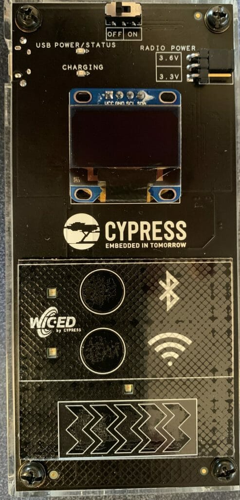
This morning I started to port the U8G2 library to MBEDOS… but ran into some problems, so I i decided to see what ports were already out there. I immediately found a port of the Adafruit_GFX library. This article talks about using it on my CY8CPROTO_062_4343W board. As part of this journey I also wanted to be able to draw the Cypress logo on the screen… so I had to figure out how to create a logo in a format that could be drawn on the screen.
I will follow these steps:
- Create a new project & add the Adafruit_GFX_library
- Create a main.cpp, configure the library and test
- Make a Cypress logo using GIMP
- Create a function to draw X11 bitmaps & test
Create a new project & add the Adafruit_GFX_library
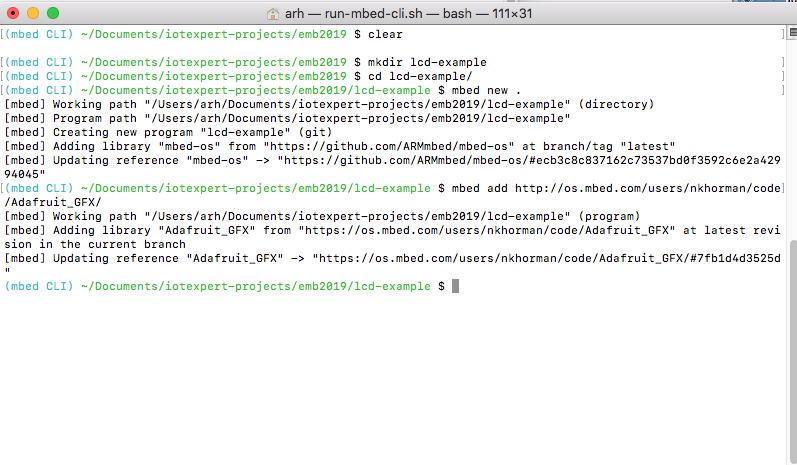
The first step to get everything going by running
- mbed new .
- mbed add http://os.mbed.com/users/nkhorman/code/Adafruit_GFX/
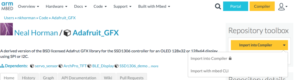
The way to figure out how to add the library is by going to the library webpage on the mbedos website. Then clicking the arrow on “Import into Compiler” where you will see two options, “Import into Compiler” and “Import with mbed CLI”
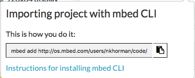
When you select that option you will get a window that tells you the exact command to run.
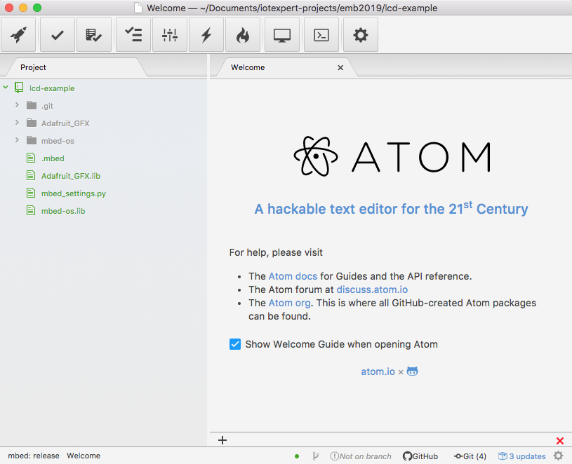
I have been using Atom as an editor (and sort of IDE). When you open the lcd-example directory using Atom you will see your project including
- The mbed-os directory with all of the mbed stuff in it.
- The Adafruit_GFX library
Create a main.cpp, configure the library and test
The next step is to create a main.cpp.
- Setup the I2C. In order to use the graphics library you need to setup a communication vehicle. In my case that is an I2C bus that is connected to P6[0] and P6[1] on my development board. Lines 6-15 create the communication class of I2CPreInit, configure it to 400kbs and connect the I2C master to P6[0]/P6[1]
- Line 16 actually setups up the graphics library and get it going.
- The main simply prints out some information about the display on lines 22-23
- Line 24 causes the current frame buffer to be displayed (more on this in a second)
- The main loop blinks the LED and prints a counter on the top of the screen.
#include "mbed.h"
#include "Adafruit_SSD1306.h"

DigitalOut myled(LED1);

class I2CPreInit : public I2C
{
public:
    I2CPreInit(PinName sda, PinName scl) : I2C(sda, scl)
    {
        frequency(400000);
        start();
    };
};
I2CPreInit gI2C(P6_1,P6_0);
Adafruit_SSD1306_I2c gOled2(gI2C,P0_2,0x78,64,128);

int main()
{   uint16_t x=0;

    printf("Started\n");
    printf("%ux%u OLED Display\r\n", gOled2.width(), gOled2.height());
    printf("Rotation = %u\n",gOled2.getRotation());
    gOled2.display();
    while(1)
    {
        x += 1;
        myled = !myled;
        gOled2.printf("%u\r",x);
        gOled2.display();
        wait(1.0);
    }
}
In order to build this thing I run “mbed compile -t GCC_ARM -m CY8CPROTO_062_4343w”. When I run the project it looks like this:
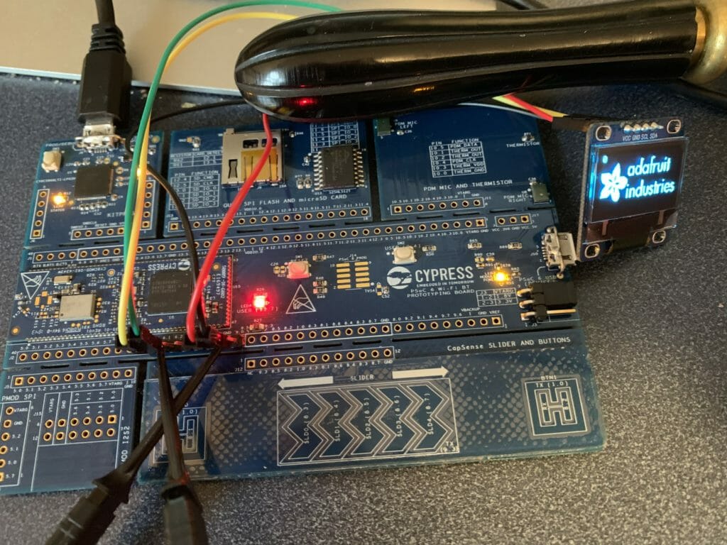
There are several things to notice about this picture. First, there is an Adafruit logo on the screen. Where did this come from? Simple on line 152 of Adafruit_ssd1306.cpp there is a function called “splash” which is called by the constructor. The spash function just copies a bitmap into the frame buffer of the Adafruit_SSD1306 object.
void Adafruit_SSD1306::splash(void)
{
#ifndef NO_SPLASH_ADAFRUIT
	uint8_t adaFruitLogo[64 * 128 / 8] =
	{
		0x00, 0x00, 0x00, 0x00, 0x00, 0x00, 0x00, 0x00, 0x00, 0x00, 0x00, 0x00, 0x00, 0x00, 0x00, 0x00,
The constructor is in Adafruit_ssd1306.h on line 152
	Adafruit_SSD1306_I2c(I2C &i2c, PinName RST, uint8_t i2cAddress = SSD_I2C_ADDRESS, uint8_t rawHeight = 32, uint8_t rawWidth = 128)
	    : Adafruit_SSD1306(RST, rawHeight, rawWidth)
	    , mi2c(i2c)
	    , mi2cAddress(i2cAddress)
	    {
		    begin();
		    splash();
		    display();
	    };
And if you don’t want to have this splash screen you can uncomment the #define NO_SPLASH_ADAFRUIT in the file “Adafruit_GFC_Config.h”
#ifndef _ADAFRUIT_GFX_CONFIG_H_
#define _ADAFRUIT_GFX_CONFIG_H_

// Uncomment this to turn off the builtin splash
#define NO_SPLASH_ADAFRUIT

// Uncomment this to enable all functionality
//#define GFX_WANT_ABSTRACTS

// Uncomment this to enable only runtime font scaling, without all the rest of the Abstracts
//#define GFX_SIZEABLE_TEXT


#endif
The next thing to notice in the picture is that I have lead wires attached to the LCD pins… and those wires are attached to a logic analyzer because I typed the I2C incorrectly and I couldn’t figure out why they didn’t talk. And finally notice my grandfathers magnifying glass which I use every day.
Make a Cypress logo using GIMP
For my project I am less interested in displaying Adafruits Logo and more interested in displaying Cypress’. To do this I loaded up the Cypress logo in Gimp.
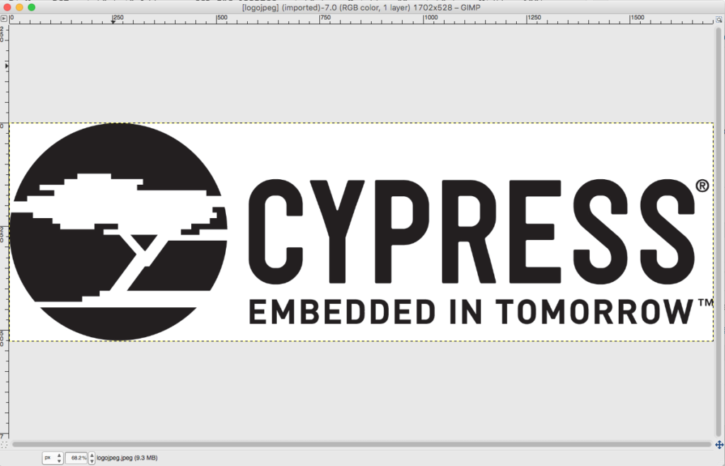
I then converted it to pure black and white using the “Image->Mode->Indexed…”

Then selected “black and white palette”
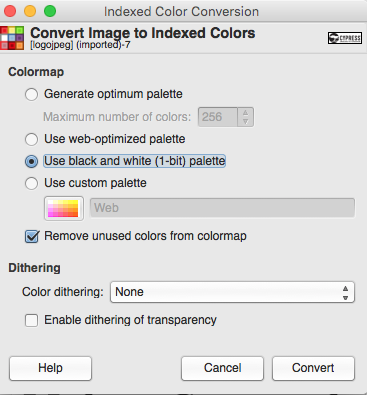
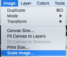
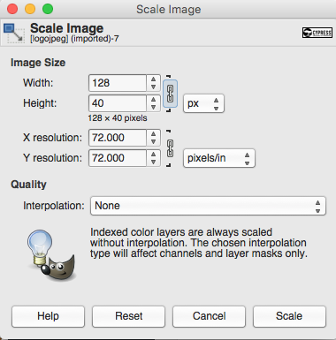
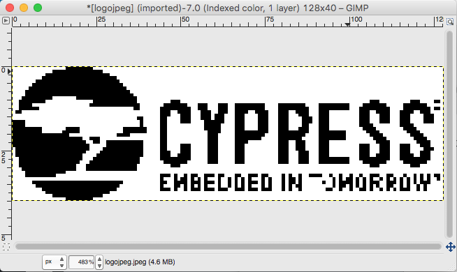
Then I scaled the image to 128×40 using the “Image->Scale Image”
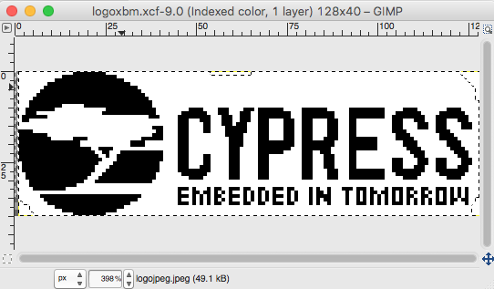
Unfortunately it made a bit of a mess of the logo during the scaling process… so I put my son to editing it.
Which looks like this after he was done. Pretty good eh?
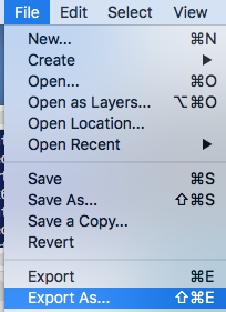
In order to use the image you need a “C program” version of it. It turns out that there is a format called “X11” or “xbm” which is exactly that (a c-file). You can read about the format on this website. To get one of these files, just run “File->Export As”
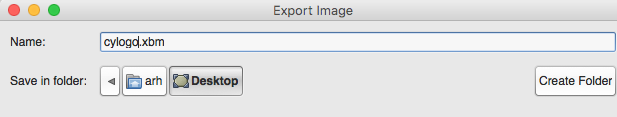
Then give it a name with a “.xbm” on the end
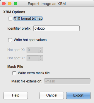
Make sure and “de-select the X10 format bitmap” (and older version of the xbm format)
When all that is said and done you will find the xbm file with goodness in it. Here is the top of it.
#define cylogo_width 128
#define cylogo_height 40
static unsigned char cylogo_bits[] = {
   0x00, 0x00, 0xff, 0x01, 0x00, 0x00, 0x00, 0x00, 0x00, 0x00, 0x00, 0x00,
   0x00, 0x00, 0x00, 0x00, 0x00, 0xe0, 0xff, 0x0f, 0x00, 0x00, 0x00, 0x00,
   0x00, 0x00, 0x00, 0x00, 0x00, 0x00, 0x00, 0x00, 0x00, 0xf8, 0xff, 0x3f,
   0x00, 0x00, 0x00, 0x00, 0x00, 0x00, 0x00, 0x00, 0x00, 0x00, 0x00, 0x00,
   0x00, 0xfe, 0xff, 0xff, 0x00, 0x00, 0x00, 0x00, 0x00, 0x00, 0x00, 0x00,
The format of this file is unsigned 8-bit integers… each bit represents the bit of one pixel… in BIG ENDIAN!!!! format. In other words this table will be 128×40/8 bytes long.
Create a function to draw X11 bitmaps & test
But how do we use this format? Well, write a new function in the Adafruit library to draw X11 bitmaps.
First add the new function name to the class on line 168 of “Adafruit_GFX.h”
virtual void drawX11BitMap(const uint8_t bitmap[],uint16_t bitMapWidth,uint16_t bitMapSize,uint16_t posX,uint16_t posY);
Then add the code.
// Write an X11 formatted bitmap to the screen at posX, posY
void Adafruit_GFX::drawX11BitMap(const uint8_t bitmap[],uint16_t bitMapWidth,uint16_t bitMapSize,uint16_t posX,uint16_t posY)
{
  int16_t x1 = posX;
  int16_t y1 = posY;

  for(unsigned int i=0;i<bitMapSize;i++)
  {
    uint8_t val = bitmap[i];

    for(int j=0;j<8;j++)
    {
        uint16_t pixColor;
        if(val>>j & 0x01)
          pixColor = 1;
        else
          pixColor = 0;

        drawPixel(x1,y1, pixColor);
        x1 = x1 + 1;
        if(x1 == posX + bitMapWidth)
        {
          x1 = posX;
          y1 = y1 + 1;
        }
    }
  }
This may not be the most beautiful code in the world… which I suppose makes it fit right in with some of the other stuff in this driver. Oh well it works.
Once you have added the function to the library, lets test it to see if it can draw the logo. First, copy the “cylogo.xbm” into the project and call it “cylogo.h”. Then modify the “main.cpp” to use it. Add an include of the “cylogo.h”. Then on line 26, call the function to draw it at 0,(half way down the screen)
#include "mbed.h"
#include "Adafruit_SSD1306.h"
#include "cylogo.h"
DigitalOut myled(LED1);

class I2CPreInit : public I2C
{
public:
    I2CPreInit(PinName sda, PinName scl) : I2C(sda, scl)
    {
        frequency(400000);
        start();
    };
};
I2CPreInit gI2C(P6_1,P6_0);
Adafruit_SSD1306_I2c gOled2(gI2C,P0_2,0x78,64,128);

int main()
{   uint16_t x=0;

    printf("Started\n");
    printf("%ux%u OLED Display\r\n", gOled2.width(), gOled2.height());
    printf("Rotation = %u\n",gOled2.getRotation());


    gOled2.drawX11BitMap(cylogo_bits,cylogo_width,sizeof(cylogo_bits),0,(64-cylogo_height)/2);

    gOled2.display();
When you program this… everything seems to be good.
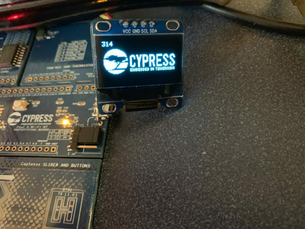
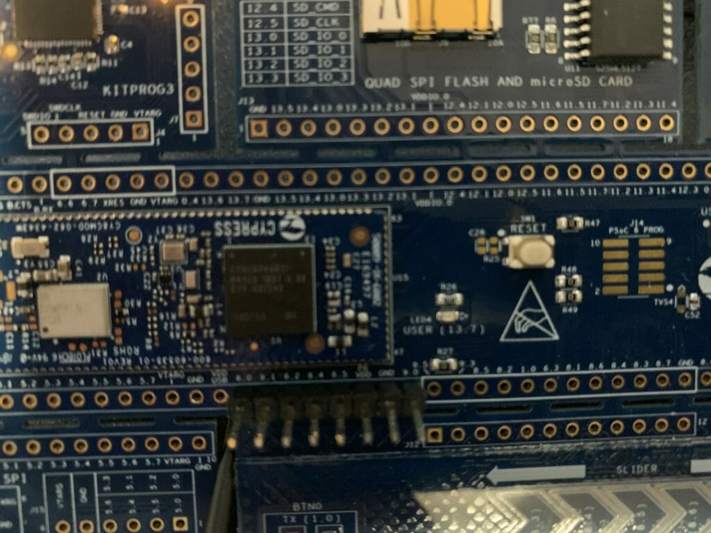
By the way if it isn’t clear by now, I did a solder in a male header onto the board so that I could attach the I2C wires for the display.
No comment yet, add your voice below!