Summary
This article takes you through the steps that I went through to figure out the startup sequence for a 2.4″ TFT MCUFriend display (Part 1), and then port it to a PSoC 6 running Segger emWin graphics library (Part 2)
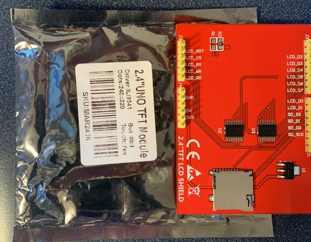
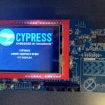
I recently tried out the Cypress CY8CKIT-028-TFT with the PSoC Creator Example Project, CE223726. This code example builds a project using the Segger EmWin library, its pretty cool. And, I have been interested in LCDs so I purchased some random LCD shields from eBay, including a rather generic looking 2.4″ TFT from bang good (a generic Chinese reseller). The entirety of the documentation is silkscreen plus the sticker you see in the picture, which just tells you that it has an ILI9341 LCD driver.
This left me with a number of questions Starting with, How do you initialize the screen? Obviously you can find the Ilitech ILI9341 datasheet, but then what? The datasheet has fifty billion parameters, and not much advice about what to do. Moreover, after googling around, I discovered that there is an absolute rogues gallery of bad advice about these screens. Horrible horrible. Finally, I found an Arduino library called “MCUFRIEND_kbv” that seemed like it was coherent. So, I installed it and got the screen working – just to prove that it worked. But I’m still not going to use an Arduino, so I need to port the initialization to my Segger emWin project.
Here is what I did to sort this out:
- Install the Arduino libraries to use the 2.4″ TFT MCUFriend Shield
- Fix & Run the Arduino Example project to prove that it works
- Modify the MCUFRIEND_kbv.c to dump the ILI9341 Startup sequence
- Verify the startup sequence against the ILI9341 data sheet (and fix the errors)
- Modify the CE223726 to use the ILI9341 shield
Install the Arduino Libraries
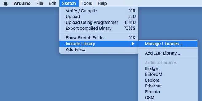
In order to use the screen I need the Arduino libraries that drive it. Start by installing the Adafruit GFX library select Sketch–>Include Library–>Manage Libraries…
In the filter box type “gfx”. Once you find the Adafruit GFX Library, you can click Install.

Then you need to install mcufriend_kbv library. Type “mcuf” into the filter. Then select install.

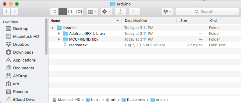
These two operations will add the directories to your library:
Fix & Run the Arduino Example project
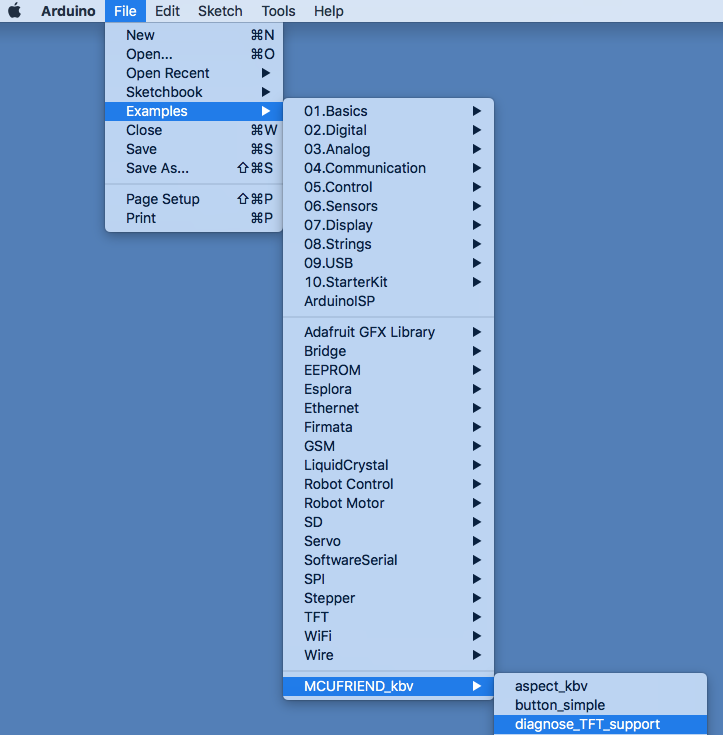
After you have added the Libraries, you can then make a project based on one of the MCUFriend existing examples. For this test case Ill pick File–>Examples–>MCUFRIEND_kbv–>diagnose_TFT_support
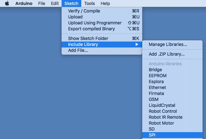
For this project to run you need to include the AdafruitGFX library. To do that select Sketch–>Include Library–>Adafruit GFX Library

And also the SPI library with Sketch–>Include Library–>SPI
Once that is done you can click on the build checkmark, then the download button and your screen should look something like this:
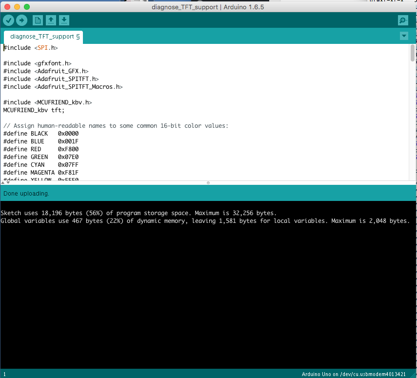
And you should have this:
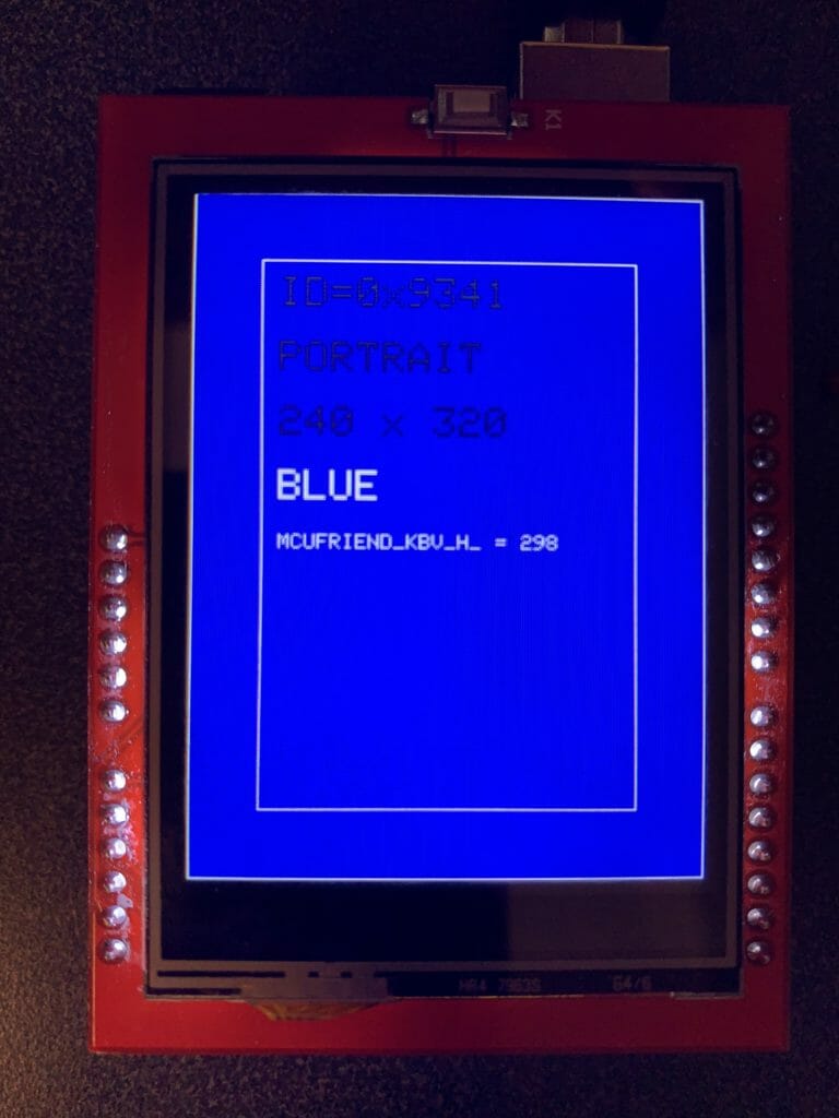
And if you start the serial port monitor you will get this:
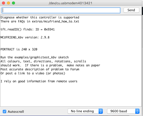
OK. This is good. This means that the screen is functioning and the Arduino library properly identifies it as a ILI9341.
Modify the MCUFRIEND_kbv.cpp
In order to get one of these screens going you need to set a bunch of parameters before you can attach it to your Graphics library. But, what is the sequence. I first started looking through the code…. but honestly it is a mess. Here is a little snip of it:
case 0x9341:
      common_9341:
        _lcd_capable = AUTO_READINC | MIPI_DCS_REV1 | MV_AXIS | READ_24BITS;
        static const uint8_t ILI9341_regValues_2_4[] PROGMEM = {        // BOE 2.4"
            0xF6, 3, 0x01, 0x01, 0x00,  //Interface Control needs EXTC=1 MV_EOR=0, TM=0, RIM=0
            0xCF, 3, 0x00, 0x81, 0x30,  //Power Control B [00 81 30]
            0xED, 4, 0x64, 0x03, 0x12, 0x81,    //Power On Seq [55 01 23 01]
            0xE8, 3, 0x85, 0x10, 0x78,  //Driver Timing A [04 11 7A]
            0xCB, 5, 0x39, 0x2C, 0x00, 0x34, 0x02,      //Power Control A [39 2C 00 34 02]
            0xF7, 1, 0x20,      //Pump Ratio [10]
            0xEA, 2, 0x00, 0x00,        //Driver Timing B [66 00]
            0xB0, 1, 0x00,      //RGB Signal [00]
            0xB1, 2, 0x00, 0x1B,        //Frame Control [00 1B]
            //            0xB6, 2, 0x0A, 0xA2, 0x27, //Display Function [0A 82 27 XX]    .kbv SS=1
            0xB4, 1, 0x00,      //Inversion Control [02] .kbv NLA=1, NLB=1, NLC=1
            0xC0, 1, 0x21,      //Power Control 1 [26]
            0xC1, 1, 0x11,      //Power Control 2 [00]
            0xC5, 2, 0x3F, 0x3C,        //VCOM 1 [31 3C]
            0xC7, 1, 0xB5,      //VCOM 2 [C0]
            0x36, 1, 0x48,      //Memory Access [00]
            0xF2, 1, 0x00,      //Enable 3G [02]
            0x26, 1, 0x01,      //Gamma Set [01]
            0xE0, 15, 0x0f, 0x26, 0x24, 0x0b, 0x0e, 0x09, 0x54, 0xa8, 0x46, 0x0c, 0x17, 0x09, 0x0f, 0x07, 0x00,
            0xE1, 15, 0x00, 0x19, 0x1b, 0x04, 0x10, 0x07, 0x2a, 0x47, 0x39, 0x03, 0x06, 0x06, 0x30, 0x38, 0x0f,
        };
Rather than try to figure out all of the stuff that I “THINK” that it sends, I decided to modify the WriteCmdParamN method to just print out what it actually sends. And I decided to print it out in a format that would be easy to import into my program: You can see that each time a command is sent, I print out the command number, followed by the number of bytes, followed by the actual bytes (this is similar to the original code).
#define ARH_DEBUG

void MCUFRIEND_kbv::WriteCmdData(uint16_t cmd, uint16_t dat) { writecmddata(cmd, dat); }

static void WriteCmdParamN(uint16_t cmd, int8_t N, uint8_t * block)
{
#ifdef ARH_DEBUG
  Serial.print(F("0x"));
  Serial.print(cmd,HEX);
    Serial.print(F(",0x"));
    Serial.print(N,HEX);
    Serial.print(F(","));
#endif

    CS_ACTIVE;
    WriteCmd(cmd);
    while (N-- > 0) {
        uint8_t u8 = *block++;
#ifdef ARH_DEBUG
  Serial.print(F("0x"));
    Serial.print(u8,HEX);
    Serial.print(F(","));
#endif
        write8(u8);
        if (N && is8347) {
            cmd++;
            WriteCmd(cmd);
        }
    }
#ifdef ARH_DEBUG
    Serial.println(F(" "));
#endif
    CS_IDLE;
}
When I download and run the program you can see that it
- Issues a reset
- Then sends the commands/data to configure the screen
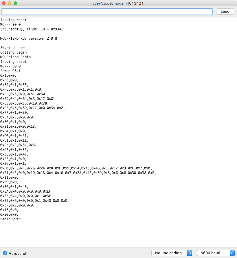
OK thats good. Now, the bad part, when I look at the commands in the ILI9341 documentation it turns out that 0xCF, 0xED, 0xE8, 0xCB, 0xF8, 0xEA and 0xF2 are not actually commands. Hmmm… I suppose that they don’t do any harm? But they also don’t appear to actually do anything. I guess beggars can’t be choosers, so I won’t be critical.
In the next Article I’ll show you how to take this startup code and put it into a PSoC with Segger emWin.
Embedded Graphics Index
Embedded Graphics
Embedded Graphics Overview
TFT Displays & Drivers
TFT Controllers
PSoC 6 + Segger EmWin + MCUFriend 2.4" TFT - Part 1
PSoC 6 + Segger EmWin + MCUFriend 2.4" TFT - Part 2
MCU Friend 3.5" Identification
No comment yet, add your voice below!