WICED Bluetooth Using the CYW20719
#
Title
Comment
0
A Two Hour WICED Bluetooth Class
WICED Bluetooth Using the CYW20719 in all its glory
1
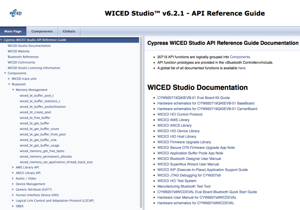
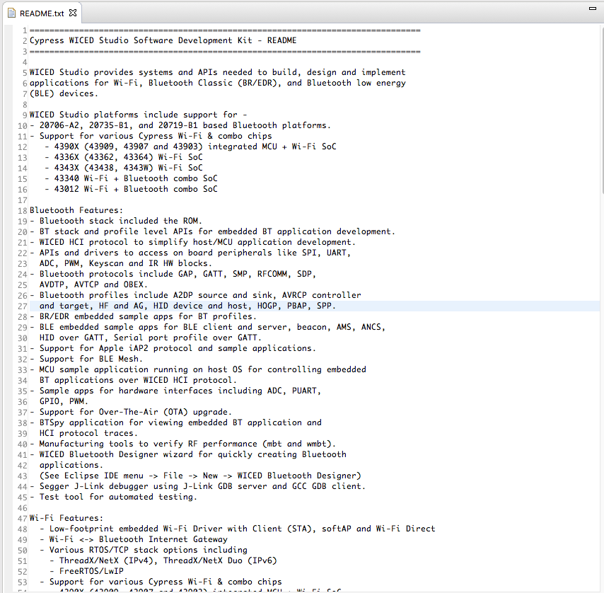
Resources
Links to all of the Cypress WICED information including videos, application notes etc.
2
Your First Project
Making Hello World & the Blinky LED
3
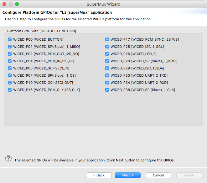
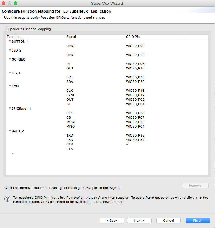
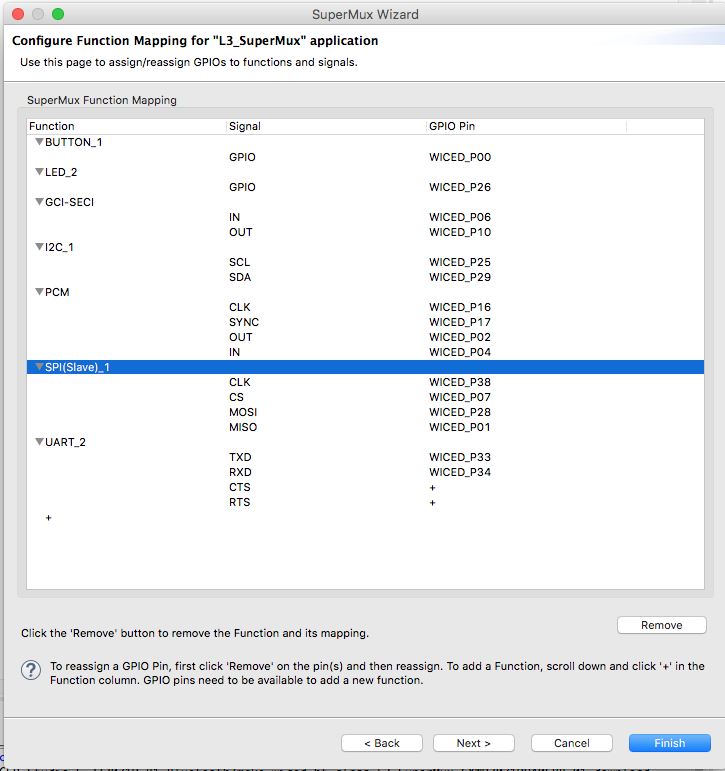
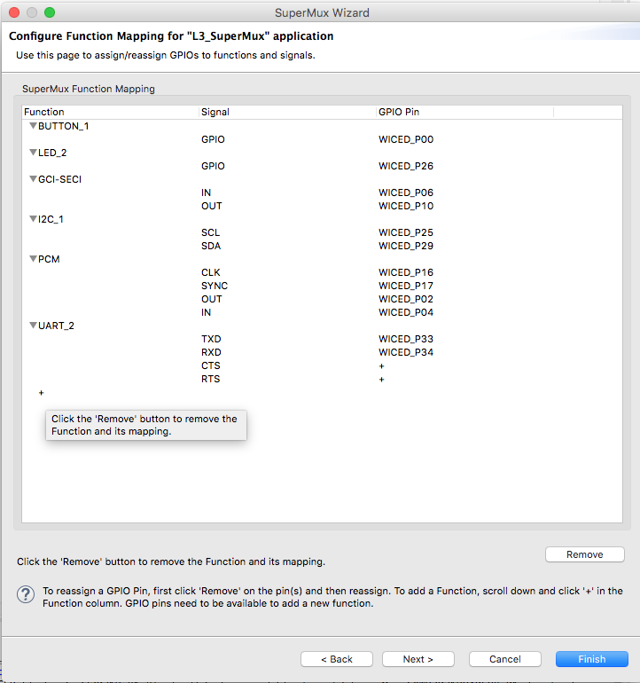
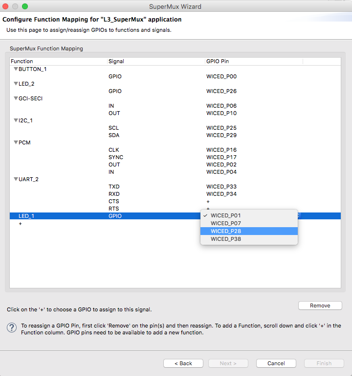
The Super Mux Tool
Learning about platforms and the Super Mux Tool
4
Snips
Using the example projects to learn Bluetooth
5
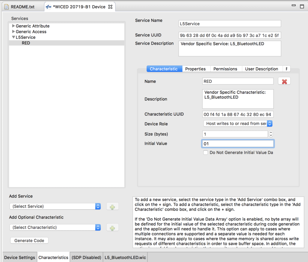
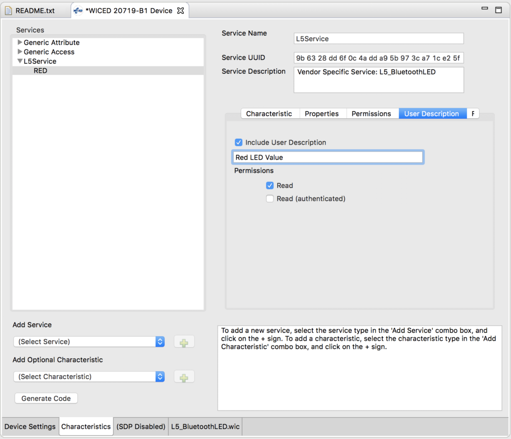
Bluetooth Designer
Using the tool to customize a project and get going fast
6
The CCCD & Notification
Writing back to the Central
7
Advertising Beacon
Building a beacon project to advertise your custom information
8
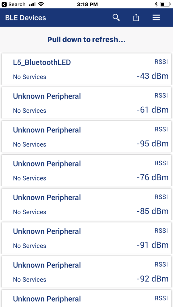
Scanner
Viewing the world around you
9
Bluetooth Classic SPP
Using the Serial Port Profile to Transmit Lots of Data
Source code:
- git@github.com:iotexpert/wiced_bt_intro.git
- https://github.com/iotexpert/wiced_bt_intro
Summary
Everywhere you go there are bunches of Bluetooth devices that are acting as beacons. Apple has a standard called iBeacon. Google has a standard called Eddystone. Some companies use those standards, and some companies make proprietary beacons. In this lesson we will build a beacon.
The important concepts in this lesson are:
- Advertising packet formats
- wiced_bt_cfg.c
The steps I will follow are:
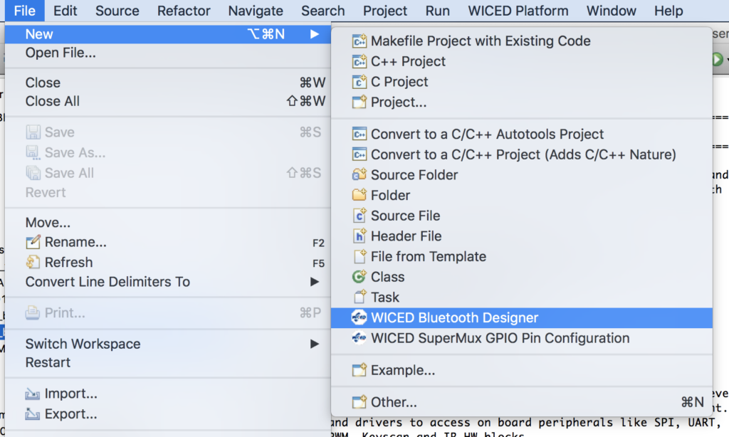
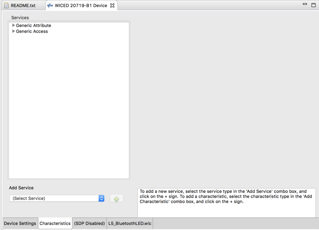
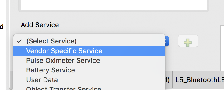
- Run BT Designer
- Setup the device as “no gatt database”
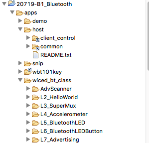
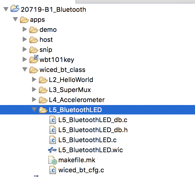
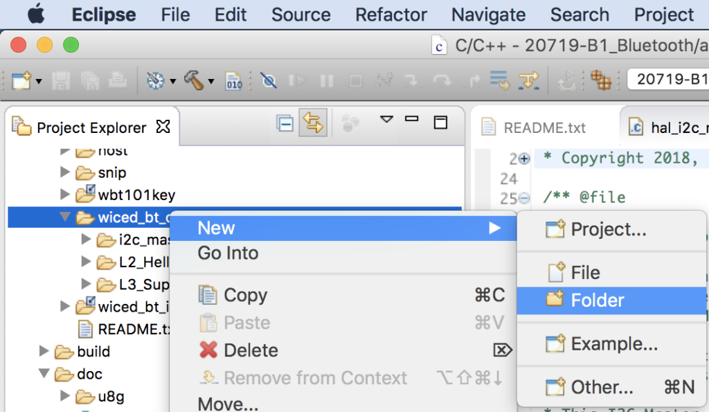
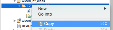
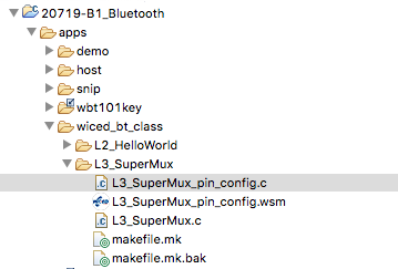
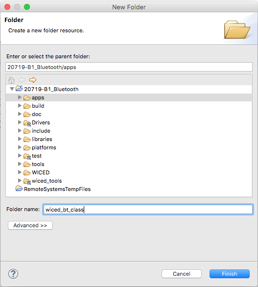
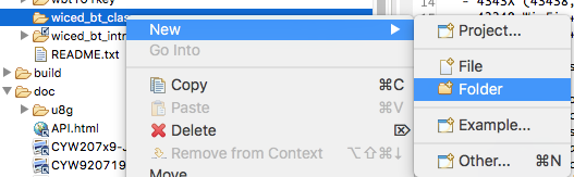
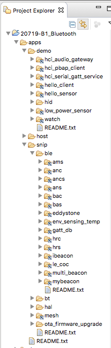
- Move the project into the wiced_bt_class folder
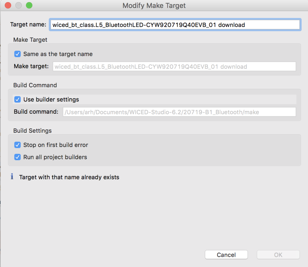
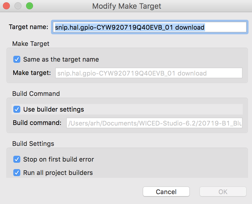
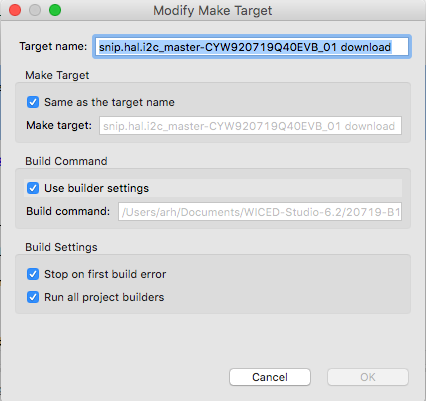
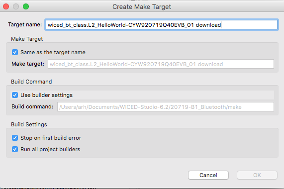
- Edit the make target
- Fix the WICED_BT_TRACE to go to the PUART
- Run it
- Edit the wiced_bt_cfg.c to never timeout
- Setup no random address changing
- Add the manufacturing data uint8_t array and include the Cypress company code
- Change the start advertising call to BTM_BLE_ADVERT_NONCONN_HIGH, BLE_ADDR_PUBLIC
- Update the length of the advertising packet
- Update the set advertising packet to have the manufacturing data
- Add a button interrupt function
- Register the button interrupt
BLE Concepts
The Advertising Packet is a string of 3-31 bytes that is broadcast at a configurable interval. The packet is broken up into variable length fields. Each field has the form:
- Length in bytes (not including the Length byte)
- Type
- Optional Data
The minimum packet requires the <<Flags>> field which is a set of flags that defines how the device behaves (e.g. is it connectable?). Here is a list of the other field Types that you can add:
/** Advertisement data types */
enum wiced_bt_ble_advert_type_e {
    BTM_BLE_ADVERT_TYPE_FLAG                        = 0x01,                 /**< Advertisement flags */
    BTM_BLE_ADVERT_TYPE_16SRV_PARTIAL               = 0x02,                 /**< List of supported services - 16 bit UUIDs (partial) */
    BTM_BLE_ADVERT_TYPE_16SRV_COMPLETE              = 0x03,                 /**< List of supported services - 16 bit UUIDs (complete) */
    BTM_BLE_ADVERT_TYPE_32SRV_PARTIAL               = 0x04,                 /**< List of supported services - 32 bit UUIDs (partial) */
    BTM_BLE_ADVERT_TYPE_32SRV_COMPLETE              = 0x05,                 /**< List of supported services - 32 bit UUIDs (complete) */
    BTM_BLE_ADVERT_TYPE_128SRV_PARTIAL              = 0x06,                 /**< List of supported services - 128 bit UUIDs (partial) */
    BTM_BLE_ADVERT_TYPE_128SRV_COMPLETE             = 0x07,                 /**< List of supported services - 128 bit UUIDs (complete) */
    BTM_BLE_ADVERT_TYPE_NAME_SHORT                  = 0x08,                 /**< Short name */
    BTM_BLE_ADVERT_TYPE_NAME_COMPLETE               = 0x09,                 /**< Complete name */
    BTM_BLE_ADVERT_TYPE_TX_POWER                    = 0x0A,                 /**< TX Power level  */
    BTM_BLE_ADVERT_TYPE_DEV_CLASS                   = 0x0D,                 /**< Device Class */
    BTM_BLE_ADVERT_TYPE_SIMPLE_PAIRING_HASH_C       = 0x0E,                 /**< Simple Pairing Hash C */
    BTM_BLE_ADVERT_TYPE_SIMPLE_PAIRING_RAND_C       = 0x0F,                 /**< Simple Pairing Randomizer R */
    BTM_BLE_ADVERT_TYPE_SM_TK                       = 0x10,                 /**< Security manager TK value */
    BTM_BLE_ADVERT_TYPE_SM_OOB_FLAG                 = 0x11,                 /**< Security manager Out-of-Band data */
    BTM_BLE_ADVERT_TYPE_INTERVAL_RANGE              = 0x12,                 /**< Slave connection interval range */
    BTM_BLE_ADVERT_TYPE_SOLICITATION_SRV_UUID       = 0x14,                 /**< List of solicitated services - 16 bit UUIDs */
    BTM_BLE_ADVERT_TYPE_128SOLICITATION_SRV_UUID    = 0x15,                 /**< List of solicitated services - 128 bit UUIDs */
    BTM_BLE_ADVERT_TYPE_SERVICE_DATA                = 0x16,                 /**< Service data - 16 bit UUID */
    BTM_BLE_ADVERT_TYPE_PUBLIC_TARGET               = 0x17,                 /**< Public target address */
    BTM_BLE_ADVERT_TYPE_RANDOM_TARGET               = 0x18,                 /**< Random target address */
    BTM_BLE_ADVERT_TYPE_APPEARANCE                  = 0x19,                 /**< Appearance */
    BTM_BLE_ADVERT_TYPE_ADVERT_INTERVAL             = 0x1a,                 /**< Advertising interval */
    BTM_BLE_ADVERT_TYPE_LE_BD_ADDR                  = 0x1b,                 /**< LE device bluetooth address */
    BTM_BLE_ADVERT_TYPE_LE_ROLE                     = 0x1c,                 /**< LE role */
    BTM_BLE_ADVERT_TYPE_256SIMPLE_PAIRING_HASH      = 0x1d,                 /**< Simple Pairing Hash C-256 */
    BTM_BLE_ADVERT_TYPE_256SIMPLE_PAIRING_RAND      = 0x1e,                 /**< Simple Pairing Randomizer R-256 */
    BTM_BLE_ADVERT_TYPE_32SOLICITATION_SRV_UUID     = 0x1f,                 /**< List of solicitated services - 32 bit UUIDs */
    BTM_BLE_ADVERT_TYPE_32SERVICE_DATA              = 0x20,                 /**< Service data - 32 bit UUID */
    BTM_BLE_ADVERT_TYPE_128SERVICE_DATA             = 0x21,                 /**< Service data - 128 bit UUID */
    BTM_BLE_ADVERT_TYPE_CONN_CONFIRM_VAL            = 0x22,                 /**< LE Secure Connections Confirmation Value */
    BTM_BLE_ADVERT_TYPE_CONN_RAND_VAL               = 0x23,                 /**< LE Secure Connections Random Value */
    BTM_BLE_ADVERT_TYPE_URI                         = 0x24,                 /**< URI */
    BTM_BLE_ADVERT_TYPE_INDOOR_POS                  = 0x25,                 /**< Indoor Positioning */
    BTM_BLE_ADVERT_TYPE_TRANS_DISCOVER_DATA         = 0x26,                 /**< Transport Discovery Data */
    BTM_BLE_ADVERT_TYPE_SUPPORTED_FEATURES          = 0x27,                 /**< LE Supported Features */
    BTM_BLE_ADVERT_TYPE_UPDATE_CH_MAP_IND           = 0x28,                 /**< Channel Map Update Indication */
    BTM_BLE_ADVERT_TYPE_PB_ADV                      = 0x29,                 /**< PB-ADV */
    BTM_BLE_ADVERT_TYPE_MESH_MSG                    = 0x2A,                 /**< Mesh Message */
    BTM_BLE_ADVERT_TYPE_MESH_BEACON                 = 0x2B,                 /**< Mesh Beacon */
    BTM_BLE_ADVERT_TYPE_3D_INFO_DATA                = 0x3D,                 /**< 3D Information Data */
    BTM_BLE_ADVERT_TYPE_MANUFACTURER                = 0xFF                  /**< Manufacturer data */
};
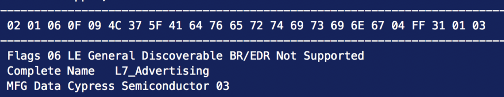
Here is an example of the advertising packet that we are going to generate
Implement the Project
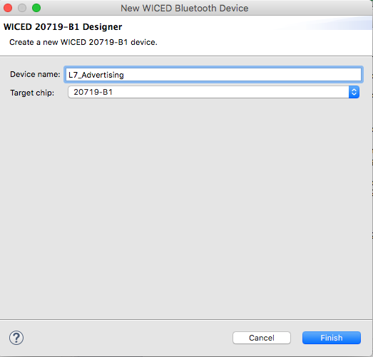
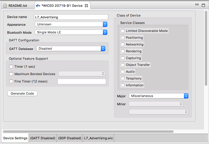
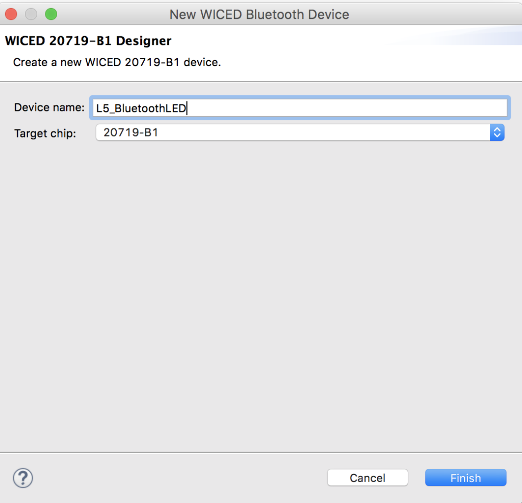
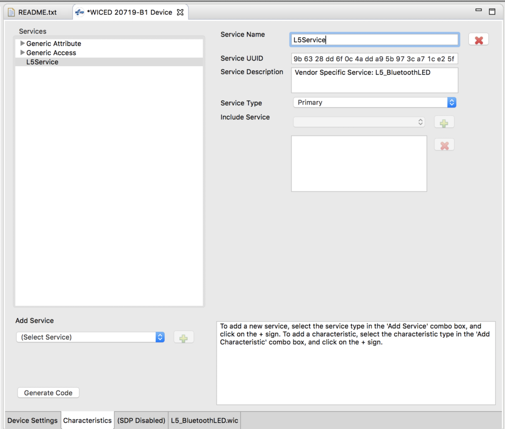
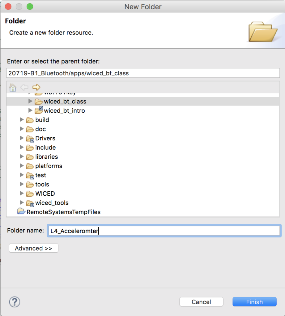
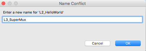
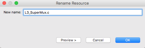
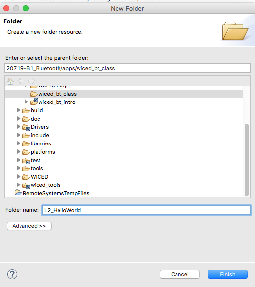
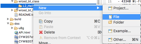
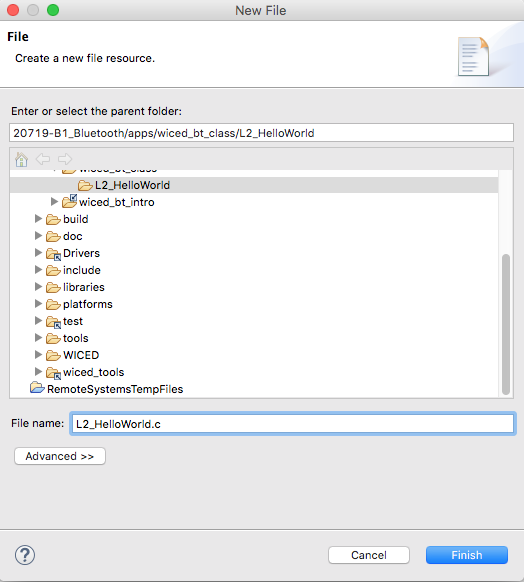
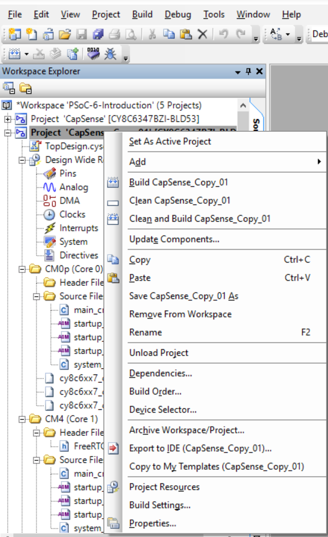
Run BT Designer and create a new project called “L7_Advertising”
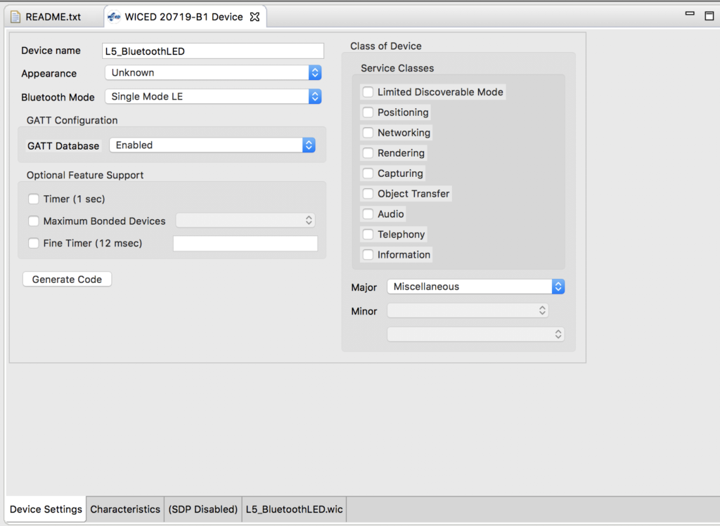
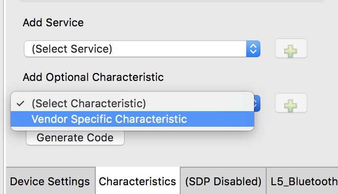
Turn off the GATT Database
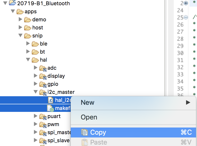
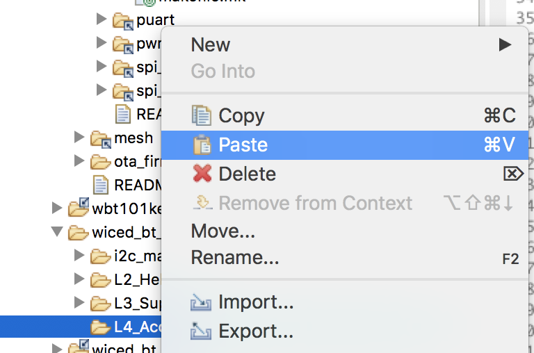
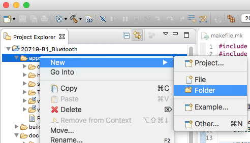
Move the project into the wiced_bt_class folder
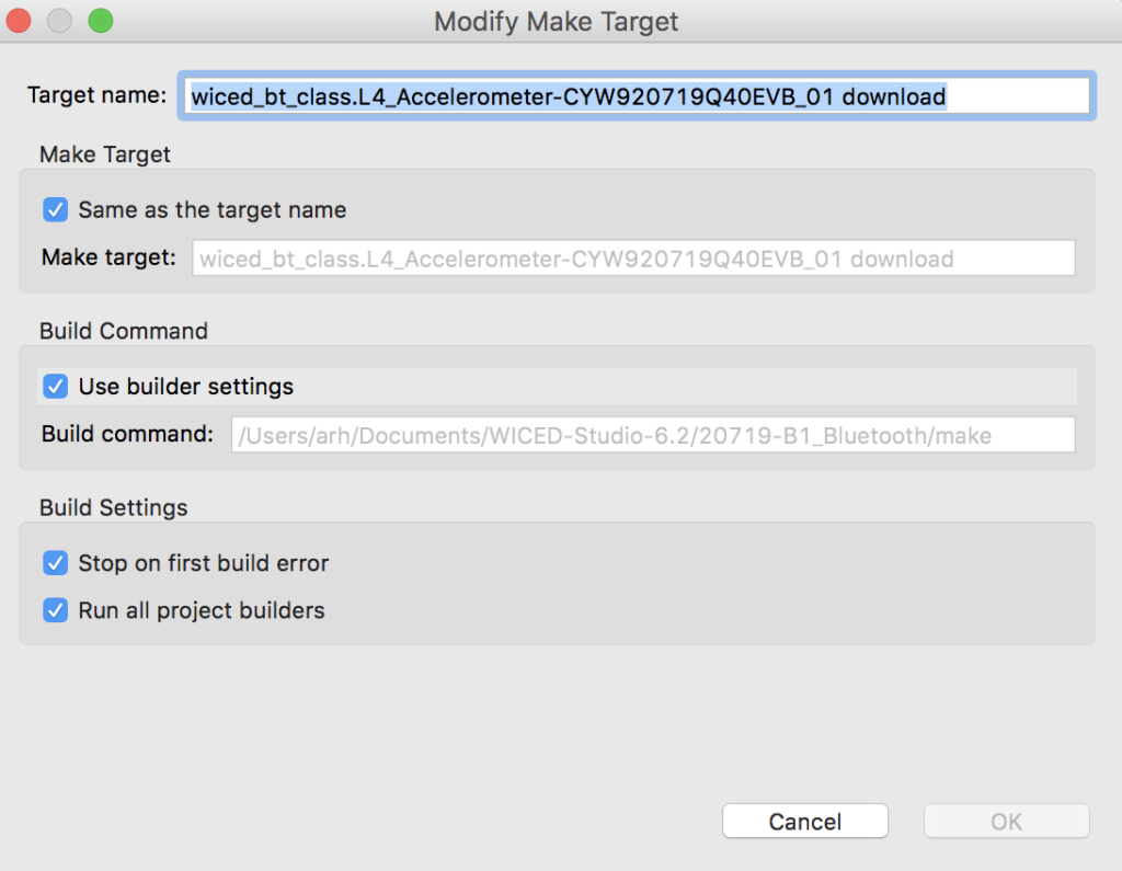
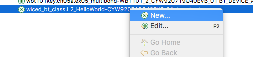
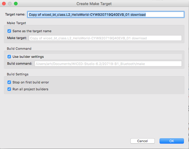
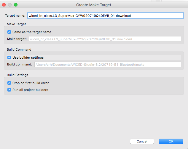
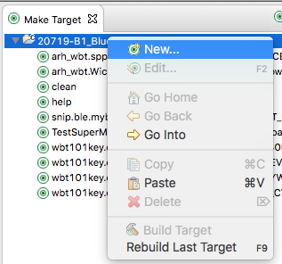
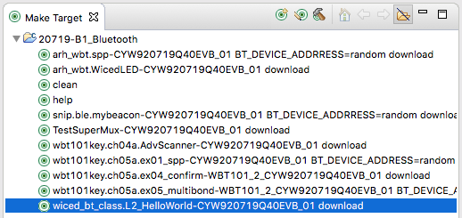
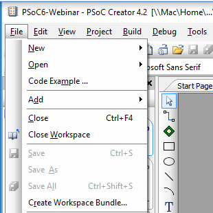
Edit the make target
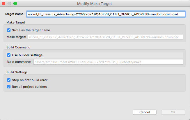
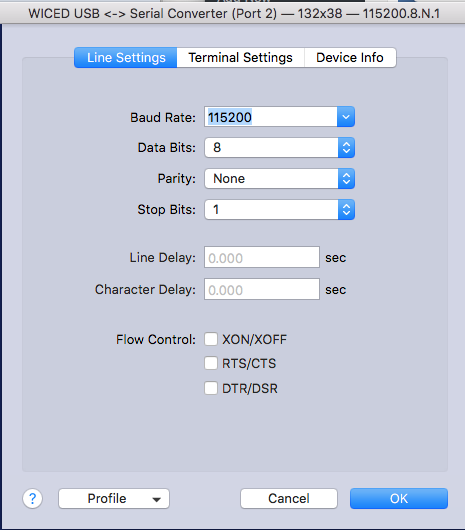
Setup the the WICED_BT_TRACE to use the PUART
#if ((defined WICED_BT_TRACE_ENABLE) || (defined HCI_TRACE_OVER_TRANSPORT))
    /* Set the Debug UART as WICED_ROUTE_DEBUG_NONE to get rid of prints */
    //  wiced_set_debug_uart( WICED_ROUTE_DEBUG_NONE );

    /* Set Debug UART as WICED_ROUTE_DEBUG_TO_PUART to see debug traces on Peripheral UART (PUART) */
      wiced_set_debug_uart( WICED_ROUTE_DEBUG_TO_PUART );

    /* Set the Debug UART as WICED_ROUTE_DEBUG_TO_WICED_UART to send debug strings over the WICED debug interface */
    //wiced_set_debug_uart( WICED_ROUTE_DEBUG_TO_WICED_UART );
#endif
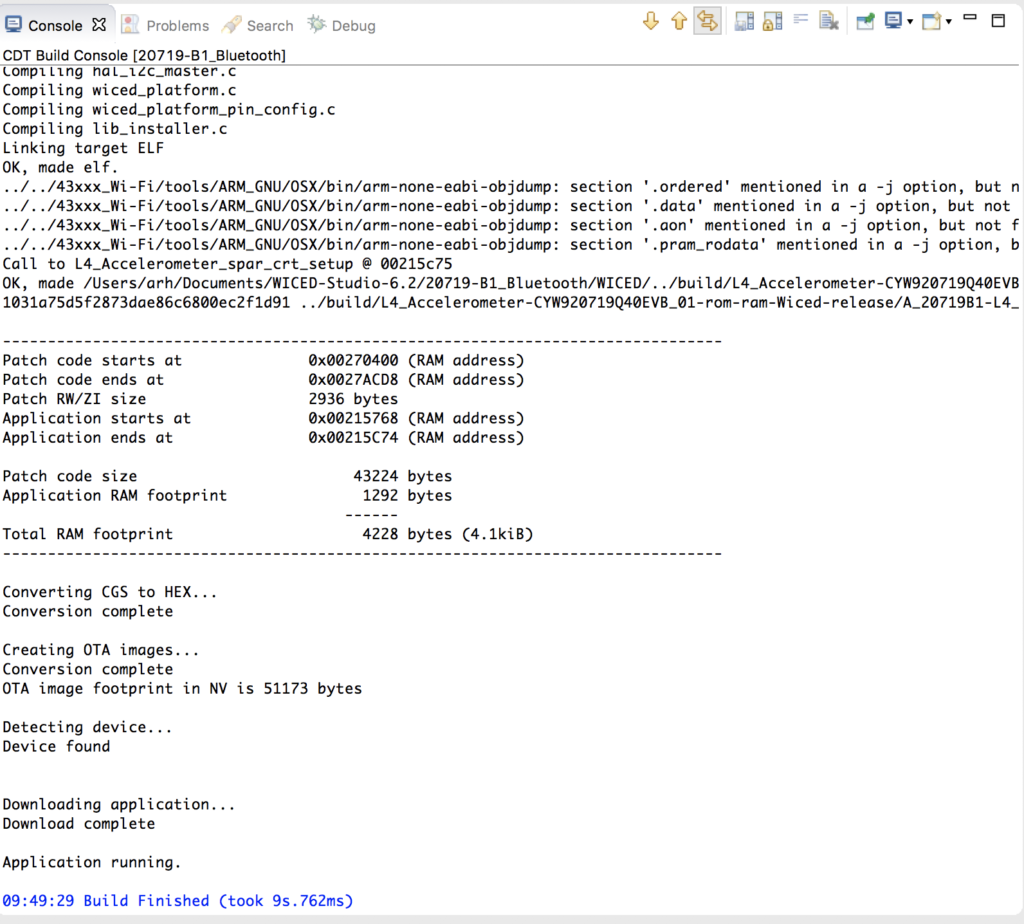
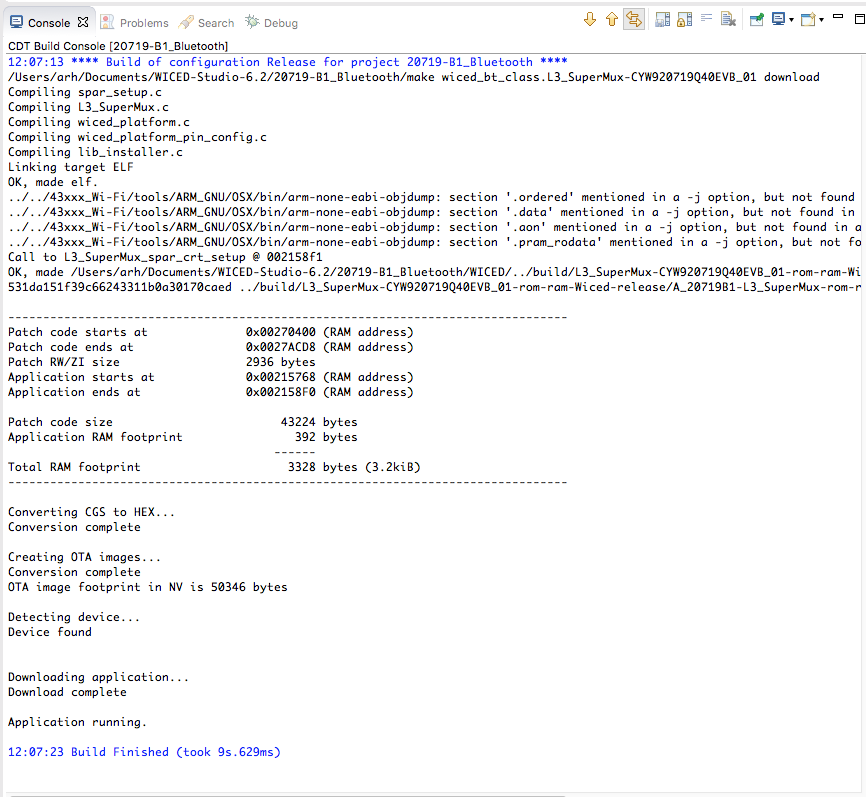
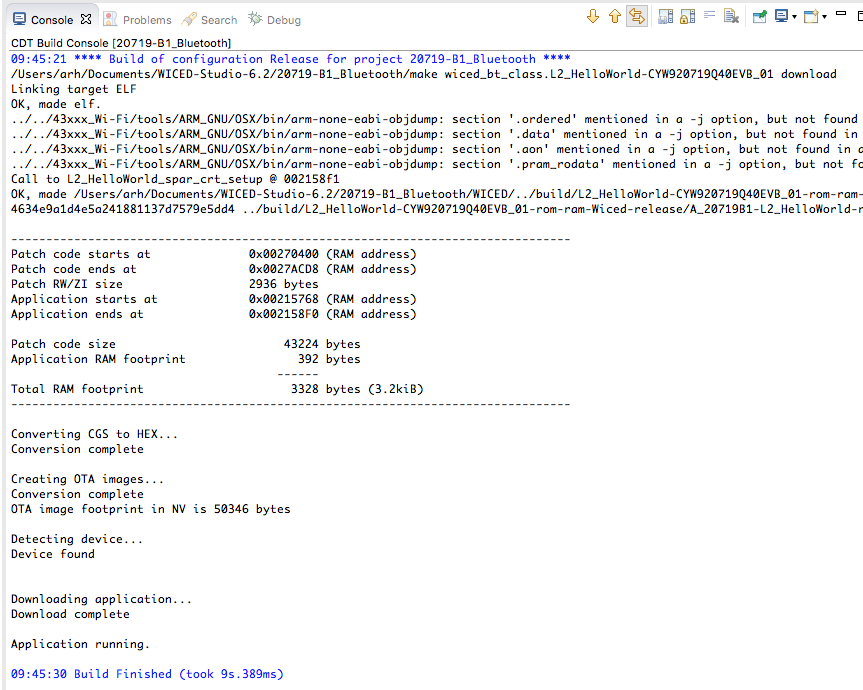
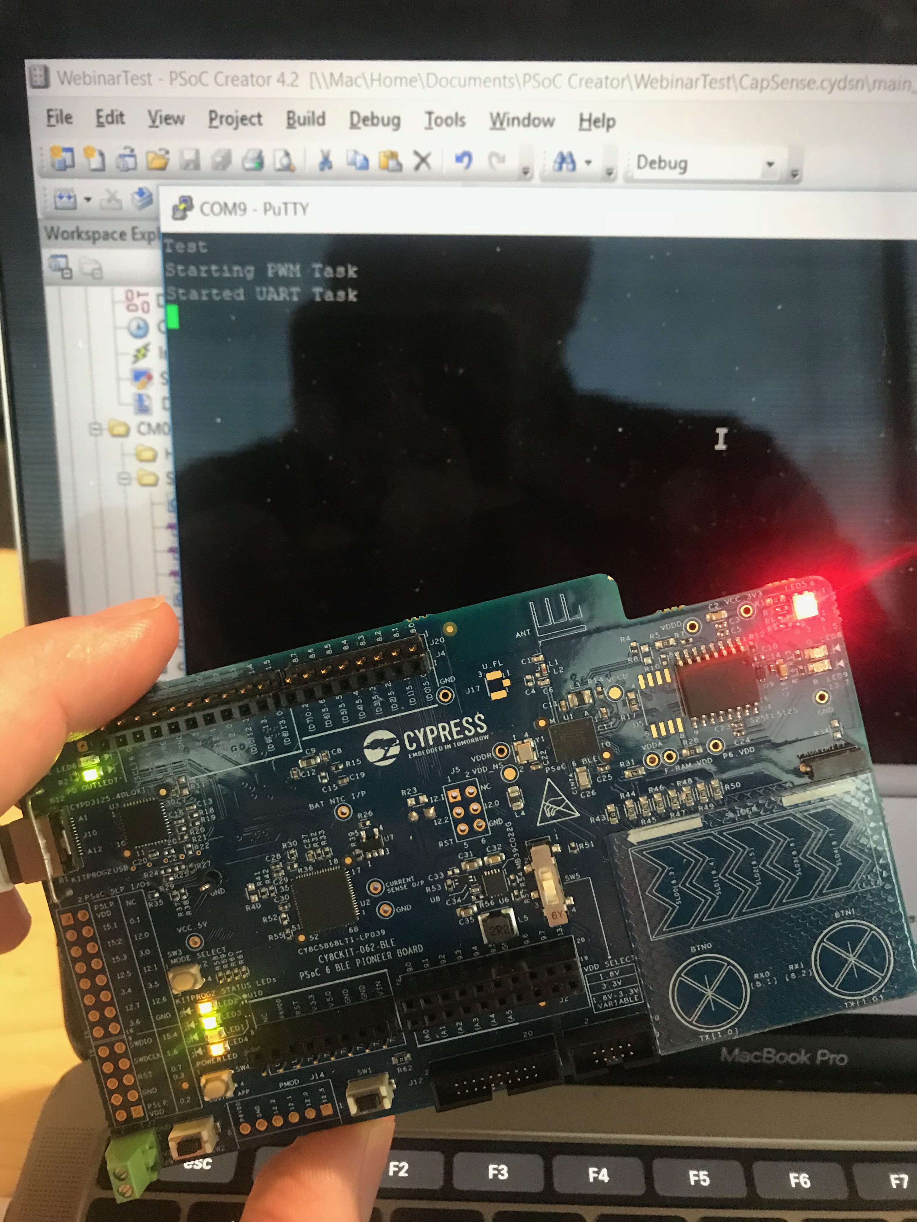
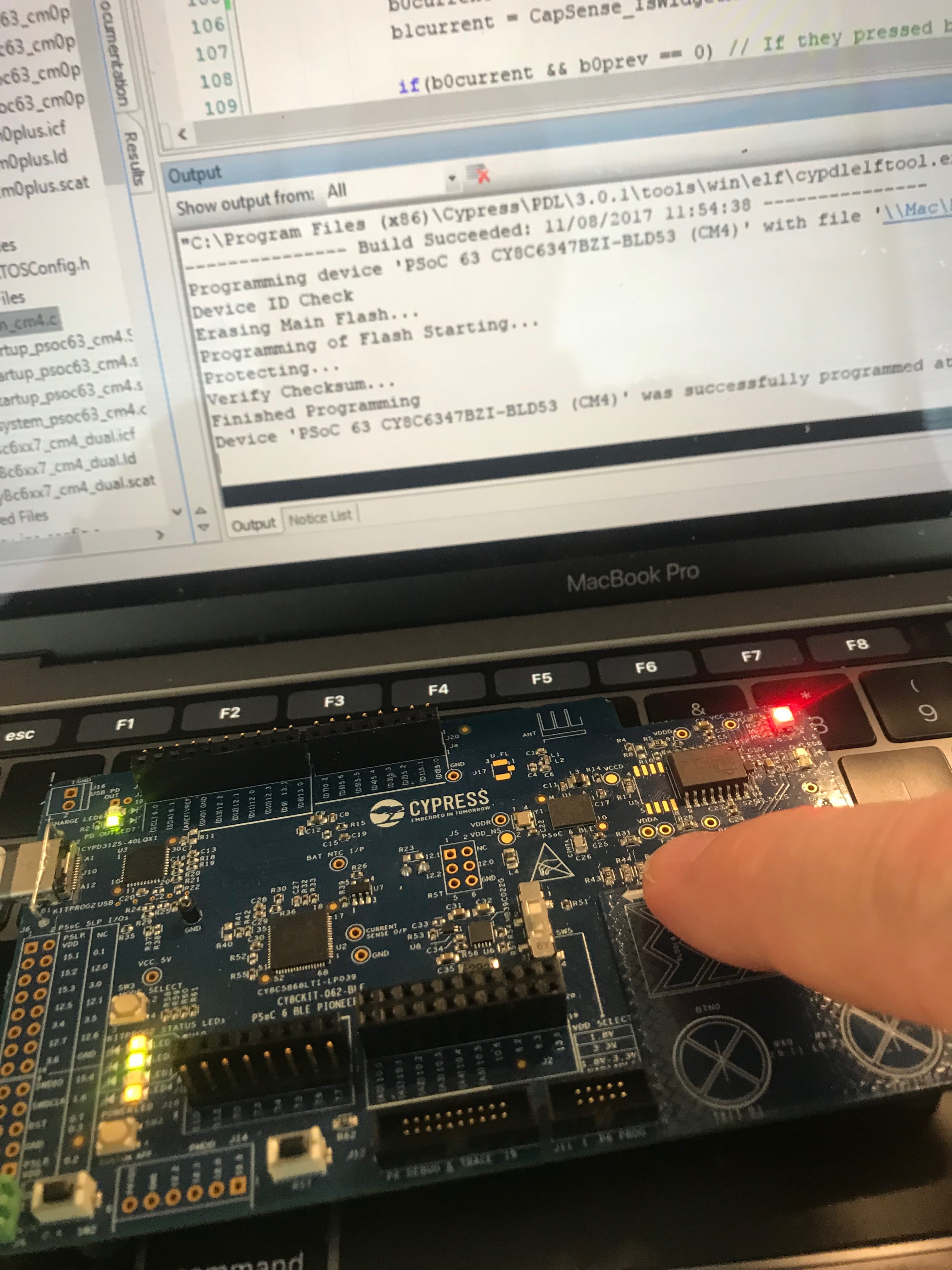
Run it
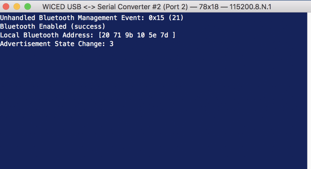
Now that we know it is working, Ill edit the wiced_bt_cfg.c to never timeout
.high_duty_nonconn_duration = 0, /**< High Duty Non-Connectable Advertising Duration in seconds (0 for infinite) */
Setup no random address changing
.rpa_refresh_timeout = WICED_BT_CFG_DEFAULT_RANDOM_ADDRESS_NEVER_CHANGE, /**< Interval of random address refreshing - secs */
Now edit the L7_Advertising.c to add the manufacturing data uint8_t array
uint8_t manuf_data[] = {0x31,0x01,0x00};
Switch to non-connectable advertising
wiced_bt_start_advertisements(BTM_BLE_ADVERT_NONCONN_HIGH, BLE_ADDR_PUBLIC, NULL);
Update the l7_advertising_set_advertisement_data function to have three elements in the advertising packet
wiced_bt_ble_advert_elem_t adv_elem[3] = { 0 };
Add the Manufacturer information to the advertising packet
    /* Advertisement Element for Manufacturer Data */
    adv_elem[num_elem].advert_type = BTM_BLE_ADVERT_TYPE_MANUFACTURER;
    adv_elem[num_elem].len = sizeof(manuf_data);
    adv_elem[num_elem].p_data = manuf_data;
    num_elem++;
Add a button interrupt function
void buttonISR(void *data, uint8_t port_pin )
{

    manuf_data[2] += 1;
    l7_advertising_set_advertisement_data();
    WICED_BT_TRACE("Manufacturer Data = %d\n",manuf_data[2]);
}
Register the button interrupt
 wiced_hal_gpio_register_pin_for_interrupt( WICED_GPIO_PIN_BUTTON_1, buttonISR, NULL );
    wiced_hal_gpio_configure_pin( WICED_GPIO_PIN_BUTTON_1, ( GPIO_INPUT_ENABLE | GPIO_PULL_UP | GPIO_EN_INT_FALLING_EDGE ), GPIO_PIN_OUTPUT_HIGH );
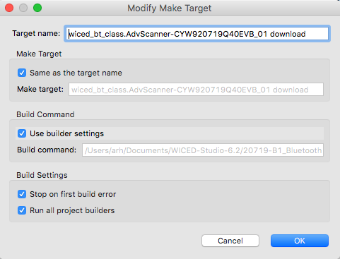
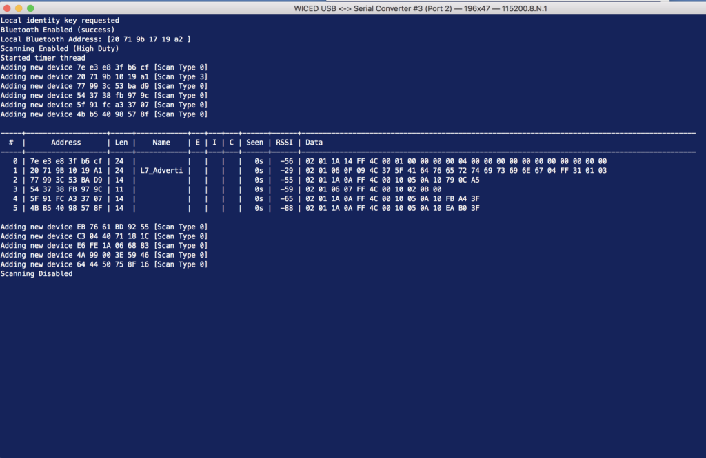
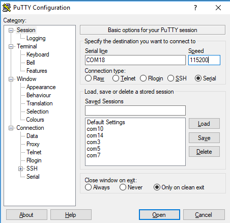
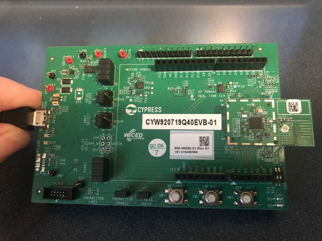
Test using the AdvScanner
I have given you a project called the “AdvScanner”. You can run it by creating a make target.
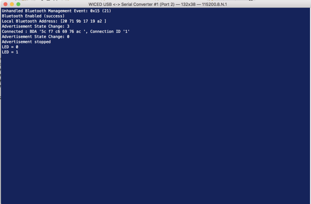
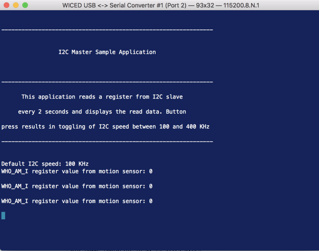
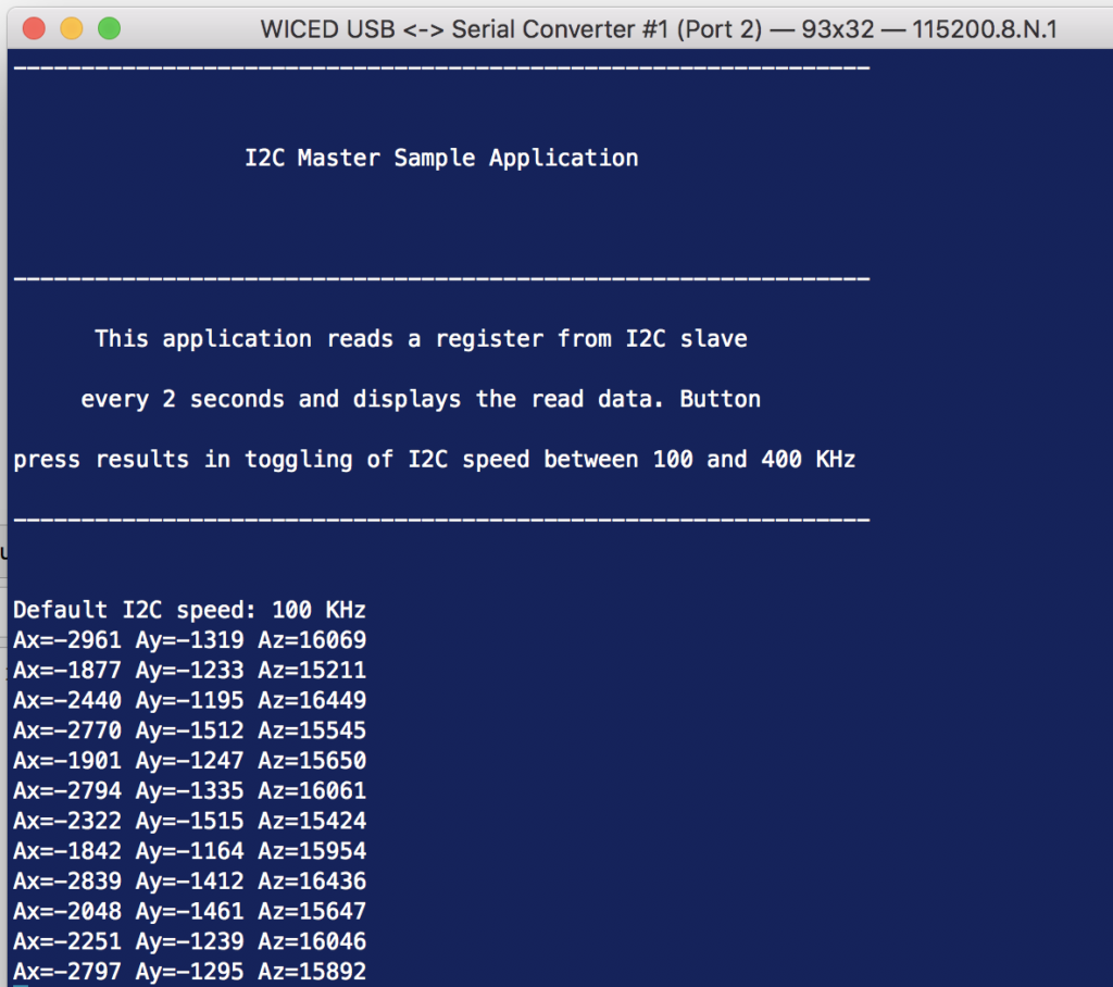
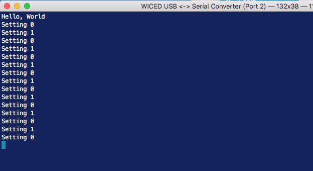
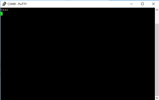
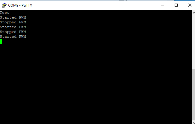
When I run the L7_Advertising project and press the buttons a few times my terminal will look like this
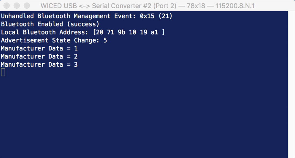
And when I look at the output of the scanner program you can see the advertising packet for the this project. Notice that the last three bytes are 31 01 03. The 03 is the count of button presses.


