IoT Design with Cypress PSoC® 6 MCUs and Wi-Fi/Bluetooth using Arm® Mbed™
#
Lesson
GitHub Project
0
Introduction
1
Developer Resources
2
Your First Project & The Blinking Thread
https://github.com/iotexpert/mouser-mbed-02.git
3
Display Thread
https://github.com/iotexpert/mouser-mbed-03.git
4
Temperature Thread
https://github.com/iotexpert/mouser-mbed-04.git
5
CapSense Thread
https://github.com/iotexpert/mouser-mbed-05.git
6
WiFi & NTP Thread
https://github.com/iotexpert/mouser-mbed-06.git
7
The CY8CKIT-062-WiFi-BT
https://github.com/iotexpert/mouser-mbed-07.git
8
Amazon AWS MQTT Thread - Part1
https://github.com/iotexpert/mouser-mbed-08.git
9
Amazon AWS MQTT Thread - Part2
https://github.com/iotexpert/mouser-mbed-09.git
You can “mbed import https://github.com/iotexpert/mouser-mbed-09.git“ to make a copy of the project in your workspace.
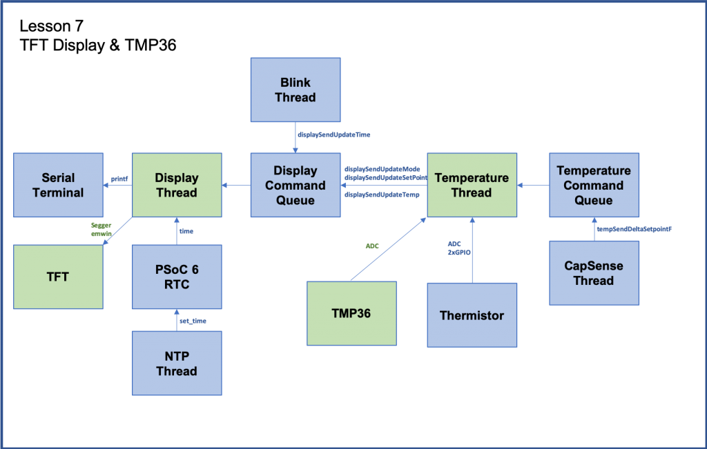
The final architecture of the thermostat looks like this.

Summary
This weekend as I was getting ready for the workshop, my son, Nicholas, was making fun of me for my user interface. To fix this I decided to show how you could move platforms. Specifically to the CY8CKIT-062-WiFi-BT which you can buy from mouser.com

You could literally just change the target and things would work… almost. The one exception is that this development kit doesn’t have a thermistor. So, I soldered a different kind of temperature sensor, called a TMP36, onto the kit which means I have to make a few small code updates to the temperatureThread.
In addition to changing to the TMP36 I will also use the TFT as a display for the system, so I need to modify the displayThread.
One of the major points that I wanted to make with this lesson is that if you design your code correctly, a change like this isn’t very hard.
To implement this I will:
- Provide a TMP36 Temperature Sensor Tutorial
- Modify the CY8CKIT-028-TFT
- Import Lesson06
- Update temperatureThread.cpp
- Build, Program and Test
- Add Segger emWin Library
- Add IoTExpert CY8CKIT-028-TFT configuration
- Update mbed_app.json to include driver
- Update displayThread.cpp
- Build, Program and Test
TMP36 Temperature Sensor
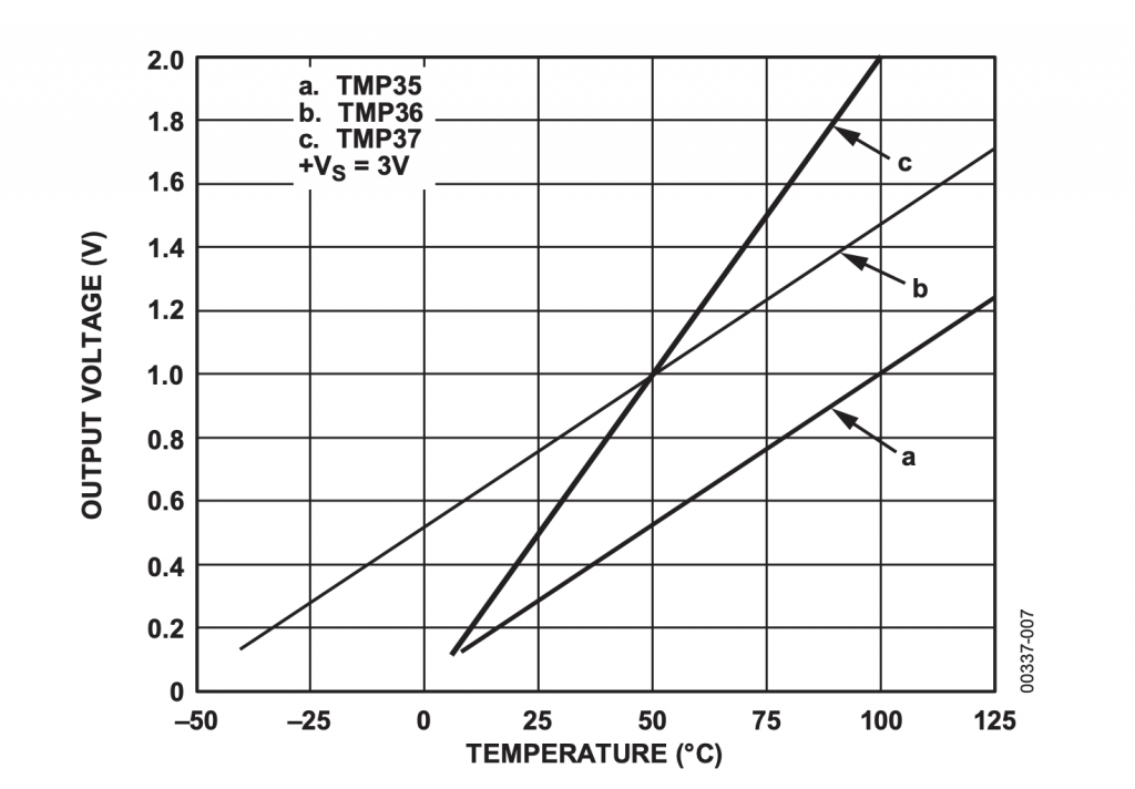
The TMP36 is a single wire temperature sensor that gives you a voltage that is directly proportional to the temperature. Specifically, it is 10mV per degree C.
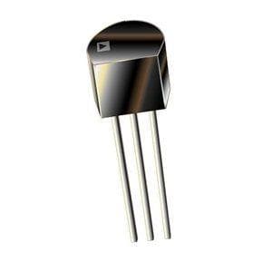
The Analog Devices TMP36 that I am using I bought here from mouser.com. It looks like a little 3-wire transistor looking thing.
Here is a snapshot from the data sheet of the temperature voltage response
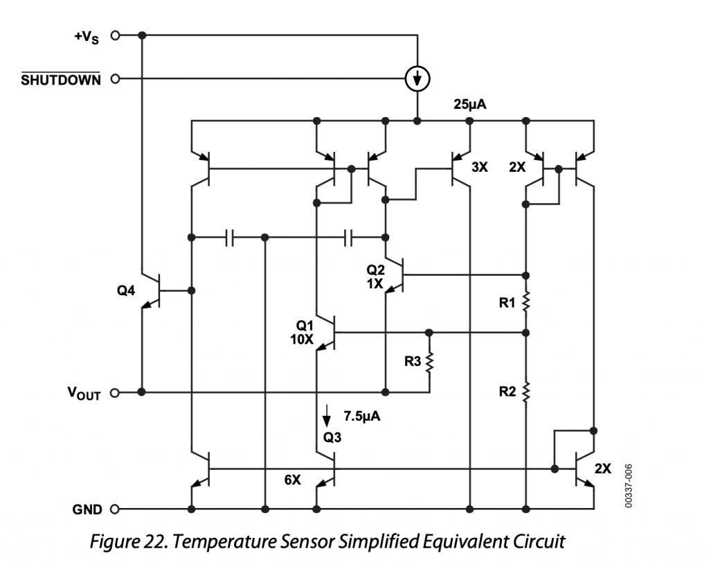
Yes I know that I am a digital guy, but for just three wires, signal, ground and power, it sure looks like there is a lot going on in the package.
The data sheet (which is actually really interesting) gives you the parameters to make the linear equation for temperature
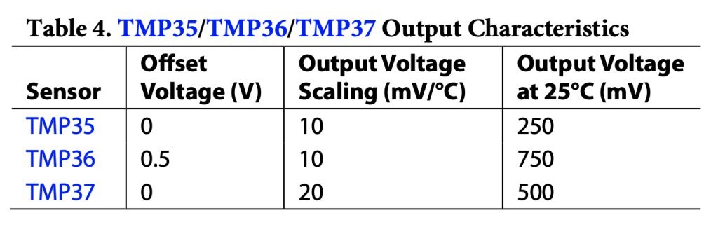
To calculate the temperature you just calculate:
T = (degree C/10mV) * V – 50 degree C
Here is the function to read the temperature:
static AnalogIn tmp36(A5);
static void readTemp()
{
    float volts;

    volts = tmp36.read() * 2.4;
    float temperatureC = 1/.01 * volts - 50.0;
    temperatureF = (temperatureC * 9.0/5.0) + 32;
}
Modify the CY8CKIT-028-TFT
Start this process by attaching the TMP36. On the back of the CY8CKIT-028-TFT I solder three wires onto the temperature sensor. One to 3.3v, one to ground and one to A5. Here is the picture of my ugly ugly solder job. Yes, that is duct-tape holding it onto the back of the shield. And yes that is a prototype sticker.
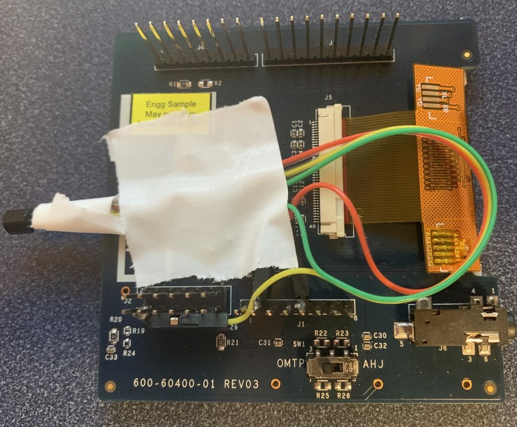
I also remove the PDM microphone which is also attached to A5 (I’m not sure that it would cause a problem… but better safe than sorry)
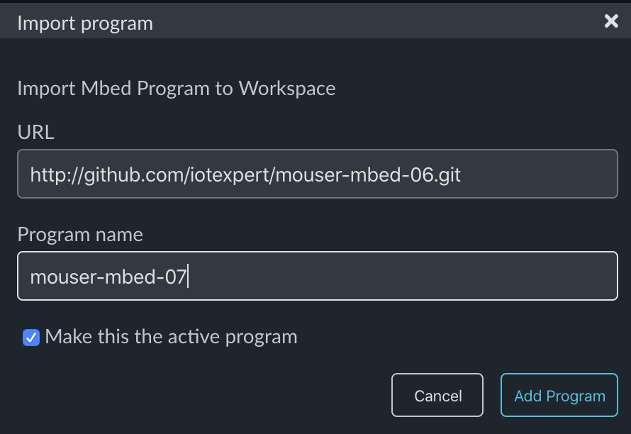
Import Lesson06
Now, fix the code. As always, start by importing the previous lesson.
https://github.com/iotexpert/mouser-mbed-06.git
Update temperatureThread.cpp
In order to switch between the thermistor and the TMP36 I create two #defines based on the target that is currently active. This is cool because the Mbed OS creates these #defines automatically.
#ifdef TARGET_CY8CPROTO_062_4343W
#define THERMISTOR
#endif

#ifdef TARGET_CY8CKIT_062_WIFI_BT
#define TMP36
#endif
There are a bunch of ways that could have been done, including with the Mbed configuration system which you control with the mbed_app.json. But this was expedient.
Next, I create the code to measure the temperature using the AnalogIn object. Notice that it is connected to the Arduino A5 pin. Also notice that when the TMP36 is active I have a different readTemp function so I don’t need to change anything else to get the temperature.
#ifdef TMP36
static AnalogIn tmp36(A5);
static void readTemp()
{
    float volts;

    volts = tmp36.read() * 2.4;
    float temperatureC = 1/.01 * volts - 50.0; // from the data sheet
    temperatureF = (temperatureC * 9.0/5.0) + 32; // conver to F
}
#endif
Then I update the thermistor readTemp function with the THERMISTOR #define
#ifdef THERMISTOR
static DigitalOut thermVDD(P10_3,1);
static DigitalOut thermGND(P10_0,0);
static AnalogIn thermOut(P10_1);

static void readTemp()
{
    float refVoltage = thermOut.read() * 2.4; // Range of ADC 0->2*Vref
    float refCurrent = refVoltage  / 10000.0; // 10k Reference Resistor
    float thermVoltage = 3.3 - refVoltage;    // Assume supply voltage is 3.3v
    float thermResistance = thermVoltage / refCurrent;
    float logrT = (float32_t)log((float64_t)thermResistance);

    /* Calculate temperature from the resistance of thermistor using Steinhart-Hart Equation */
    float stEqn = (float32_t)((0.0009032679) + ((0.000248772) * logrT) +
                             ((2.041094E-07) * pow((float64)logrT, (float32)3)));

    float temperatureC = (float32_t)(((1.0 / stEqn) - 273.15)  + 0.5);
    temperatureF = (temperatureC * 9.0/5.0) + 32;
}
#endif
Here is the whole file:
#include "mbed.h"
#include "temperatureThread.h"
#include "displayThread.h"


#ifdef TARGET_CY8CPROTO_062_4343W
#define THERMISTOR
#endif

#ifdef TARGET_CY8CKIT_062_WIFI_BT
#define TMP36
#endif


static float temperatureF;
static float setPoint = 75.0;

static void readTemp();

typedef enum {
    CMD_setPointDelta,
    CMD_setPoint,

} command_t;


typedef struct {
    command_t cmd;
    float    value;   /* AD result of measured voltage */
} msg_t;


static Queue<msg_t, 32> queue;
static MemoryPool<msg_t, 16> mpool;

void tempSendDeltaSetpointF(float delta)
{
    msg_t *message = mpool.alloc();
    if(message)
    {
        message->cmd = CMD_setPointDelta;
        message->value = delta;
        queue.put(message);
    }
}

void tempSendUpdateCurrentSetPointF(float setPoint)
{
    msg_t *message = mpool.alloc();
    if(message)
    {
        message->cmd = CMD_setPoint;
        message->value = setPoint;
        queue.put(message);
    }
}

void temperatureThread()
{

    char buffer[128];
    displaySendUpdateTemp(temperatureF);
    displaySendUpdateSetPoint(setPoint);

    while(1)
    {
        osEvent evt = queue.get(200);
        if (evt.status == osEventMessage) {
            msg_t *message = (msg_t*)evt.value.p;
            switch(message->cmd)
            {
                case CMD_setPointDelta:
                    setPoint += message->value;
                    displaySendUpdateSetPoint(setPoint);
                break;
                case CMD_setPoint:
                    setPoint = message->value;
                    displaySendUpdateSetPoint(setPoint);
                break;

            }
            mpool.free(message);

        }
        else
        {
            readTemp();

            // Control the HVAC system with +- 0.5 degree of Hystersis
            if(temperatureF < setPoint - 0.5)
                displaySendUpdateMode(-1.0);
            else if (temperatureF > setPoint + 0.5)
                displaySendUpdateMode(1.0);
            else
                displaySendUpdateMode(0.0);

            displaySendUpdateTemp(temperatureF);

        }
    }

}


#ifdef THERMISTOR
static DigitalOut thermVDD(P10_3,1);
static DigitalOut thermGND(P10_0,0);
static AnalogIn thermOut(P10_1);

static void readTemp()
{
    float refVoltage = thermOut.read() * 2.4; // Range of ADC 0->2*Vref
    float refCurrent = refVoltage  / 10000.0; // 10k Reference Resistor
    float thermVoltage = 3.3 - refVoltage;    // Assume supply voltage is 3.3v
    float thermResistance = thermVoltage / refCurrent;
    float logrT = (float32_t)log((float64_t)thermResistance);

    /* Calculate temperature from the resistance of thermistor using Steinhart-Hart Equation */
    float stEqn = (float32_t)((0.0009032679) + ((0.000248772) * logrT) +
                             ((2.041094E-07) * pow((float64)logrT, (float32)3)));

    float temperatureC = (float32_t)(((1.0 / stEqn) - 273.15)  + 0.5);
    temperatureF = (temperatureC * 9.0/5.0) + 32;
}
#endif

#ifdef TMP36
static AnalogIn tmp36(A5);
static void readTemp()
{
    float volts;

    volts = tmp36.read() * 2.4;
    float temperatureC = 1/.01 * volts - 50.0;
    temperatureF = (temperatureC * 9.0/5.0) + 32;
}
#endif
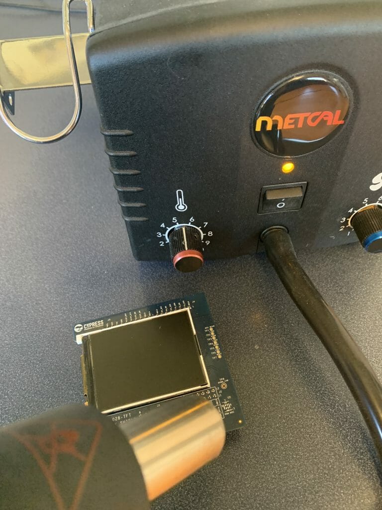
Build, Program and Test
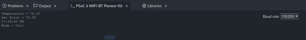
With that little update I can now build, program and test. Notice that my display is still working… and I can change the temperature by holding the TMP36 between my fingers.
Add Segger emWin Library
But, I haven’t really addressed Nicholas’ complaint, the GUI. To do this I am going to use the Segger emWin library to control the TFT display. Go to the library manager and add the library.
https://github.com/cypresssemiconductorco/emwin.git
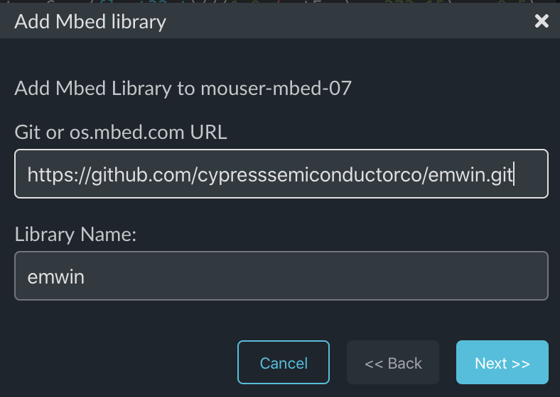
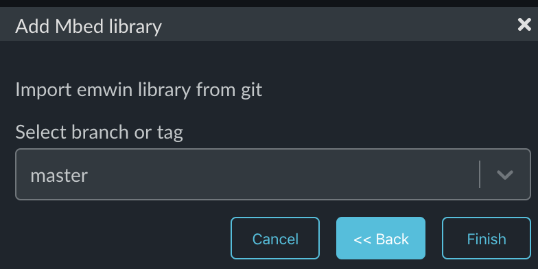
Use the master branch:
Add IoTExpert CY8CKIT-028-TFT configuration
The emWin library doesn’t know anything about how the TFT is attached. So, I created a driver library which you can use for all of the Cypress development kits.
https://github.com/iotexpert/mbed-os-emwin-st7789v.git

Use the master branch:

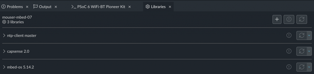
Now your libraries should look like this.
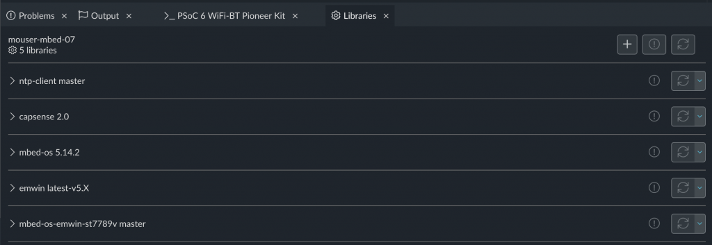
Update mbed_app.json to include emWin Driver
In order to use this driver you need to tell Mbed OS to add the correct archive file. To do this update mbed_app.json
{
    "target_overrides": {
        "*": {
            "target.components_add": ["EMWIN_OSNTS"],
            "platform.stdio-baud-rate": 115200
        }
    }
}
Update displayThread.cpp
Finally update the displayThread. Start by adding the include for the Segger library.
#ifdef TARGET_CY8CKIT_062_WIFI_BT
#include "GUI.h"
#endif
Then update the displayAtXY function to also print on the display. By doing it here I don’t have to change anything else in the code because this is the only function that draws on the screen.
static void displayAtXY(int x, int y,char *buffer)
{
    #ifdef TARGET_CY8CKIT_062_WIFI_BT
    GUI_SetTextAlign(GUI_TA_LEFT);
    GUI_DispStringAt(buffer,(x-1)*8,(y-1)*16); // 8x16 font
    #endif
    // row column
    printf("\033[%d;%dH%s",y,x,buffer);
    fflush(stdout);
}
Update the main thread to initialize the display when the thread starts.
void displayThread()
{
    char buffer[128];

    printf("\033[2J\033[H"); // Clear Screen and go Home
    printf("\033[?25l"); // Turn the cursor off
    fflush(stdout);

    #ifdef TARGET_CY8CKIT_062_WIFI_BT
        GUI_Init();
        GUI_SetColor(GUI_WHITE);
        GUI_SetBkColor(GUI_BLACK);
        GUI_SetFont(GUI_FONT_8X16_1);
    #endif
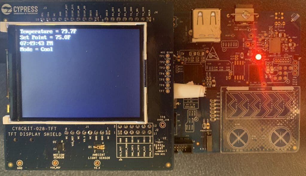
Build, Program and Test
When you program, now you should have a TFT display. Happy Nicholas?
No comment yet, add your voice below!