Summary
In the last several articles I have written about how to use and talk to the Matrix Orbital GTT43A. Now it is time to write some code. The PSoC4 program that I am going to show you has evolved over time as I added stuff to it. For instance, while I was working on this program I ran into a problem where the I2C Bus would hang (the subject of the next article). As such, some of the code that is in this program was written to help me debug that problem. With that said, I wanted a program that:
- Is command line driven i.e. I can interact with my program via serial commands through the PC COM Port
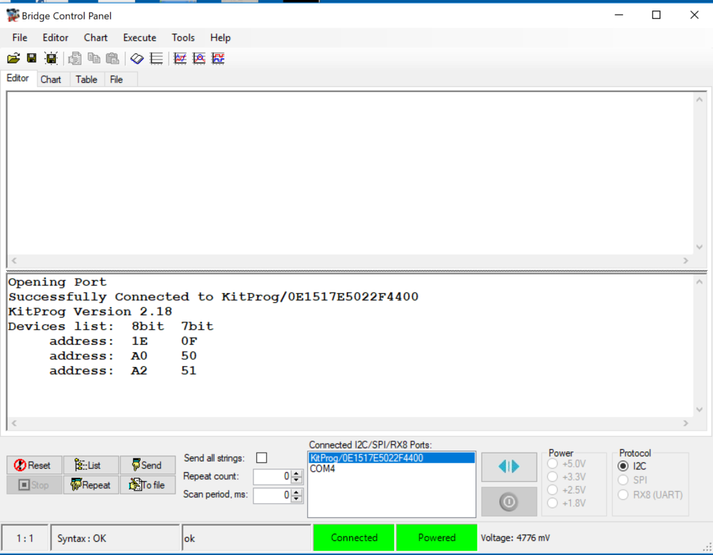
- Can read 1 byte at a time (like I do on the bridge control panel)
- Can test the “read whole packet” code
- Can selectively send commands via a I2C or the UART
- Send test commands to the display e.g. reset, clear
- Test the display generated messages (like button presses)
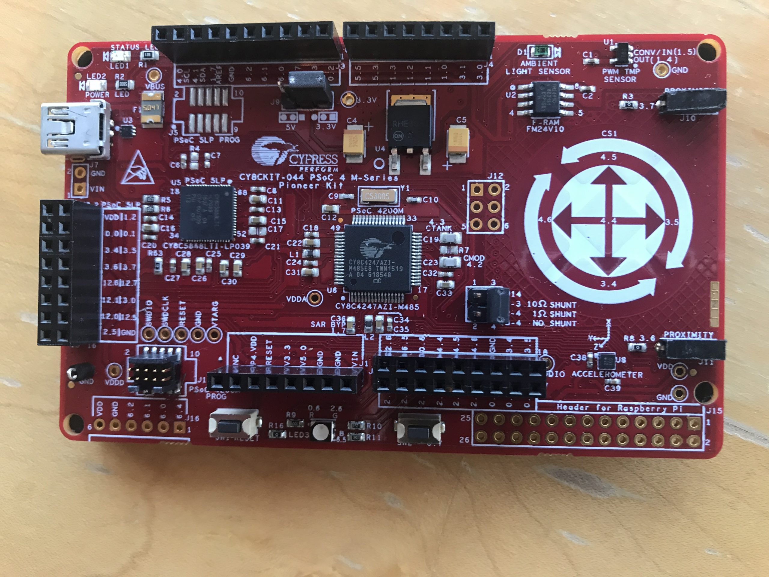
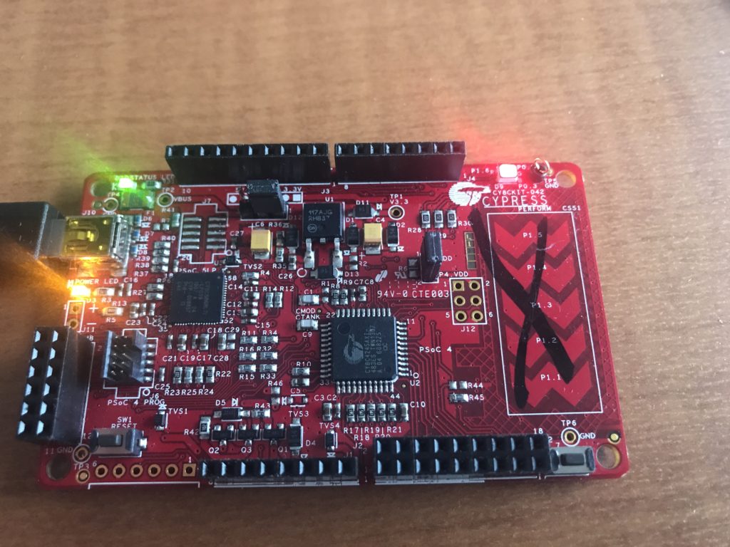
All of this code was built to run on the CY8CKIT-044 which has a PSoC 4200M MCU
Schematic & Pin Assignment
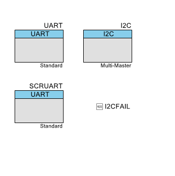
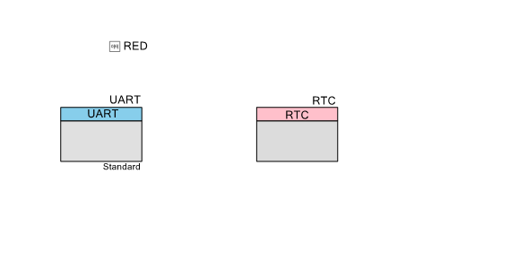
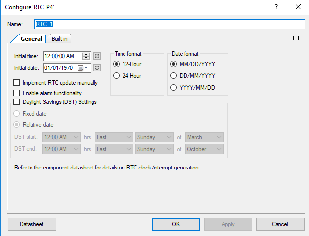
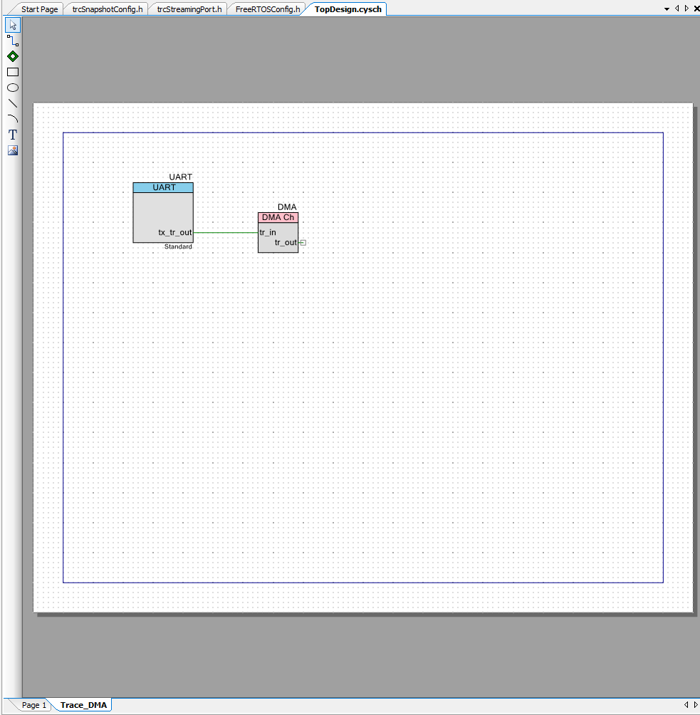
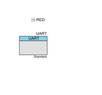
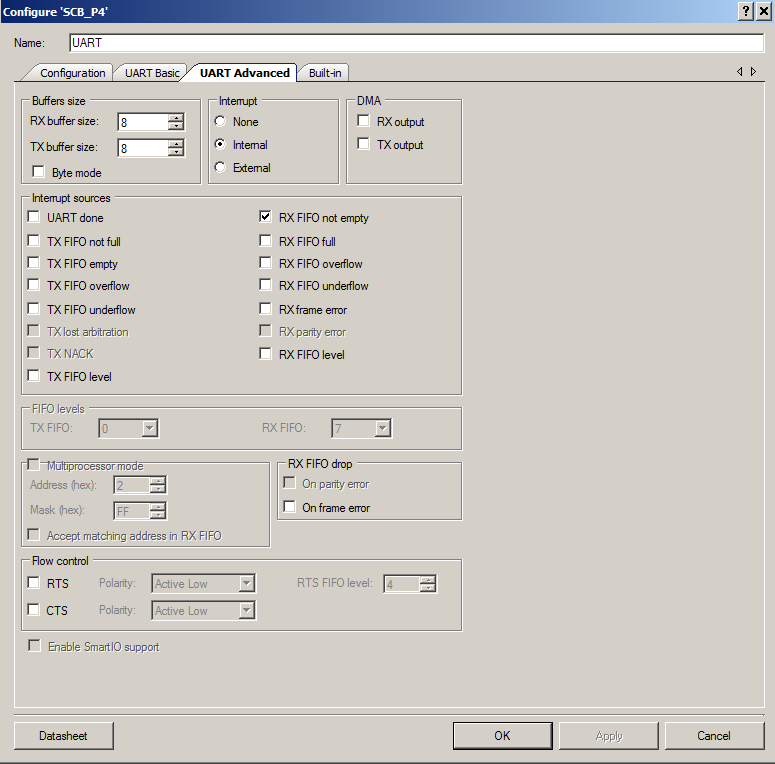
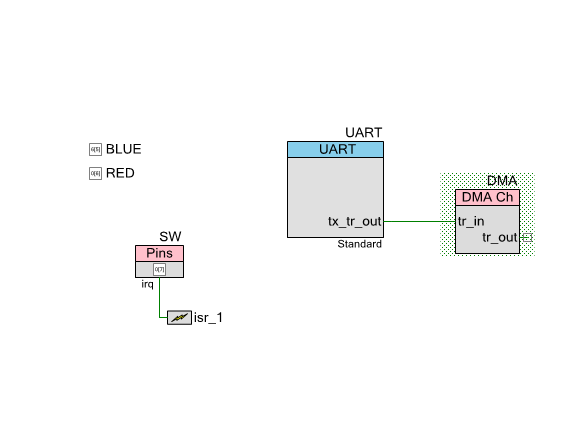
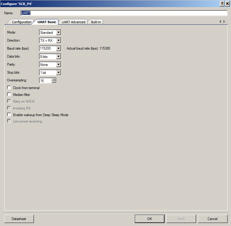
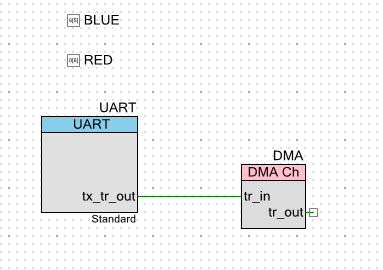
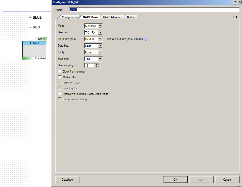
All PSoC 4 projects start with a schematic. In my schematic I have a UART setup to talk to the KitProg (called UART) and serve as the command processor, an I2C which directly attaches to the I2C bus that drives the display, and a UART that is also attached to the display which I called SCRUART.
The I2CFAIL pin in the schematic I used to help me debug the I2C problem (the subject of the next article)
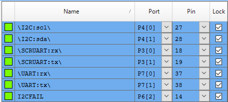
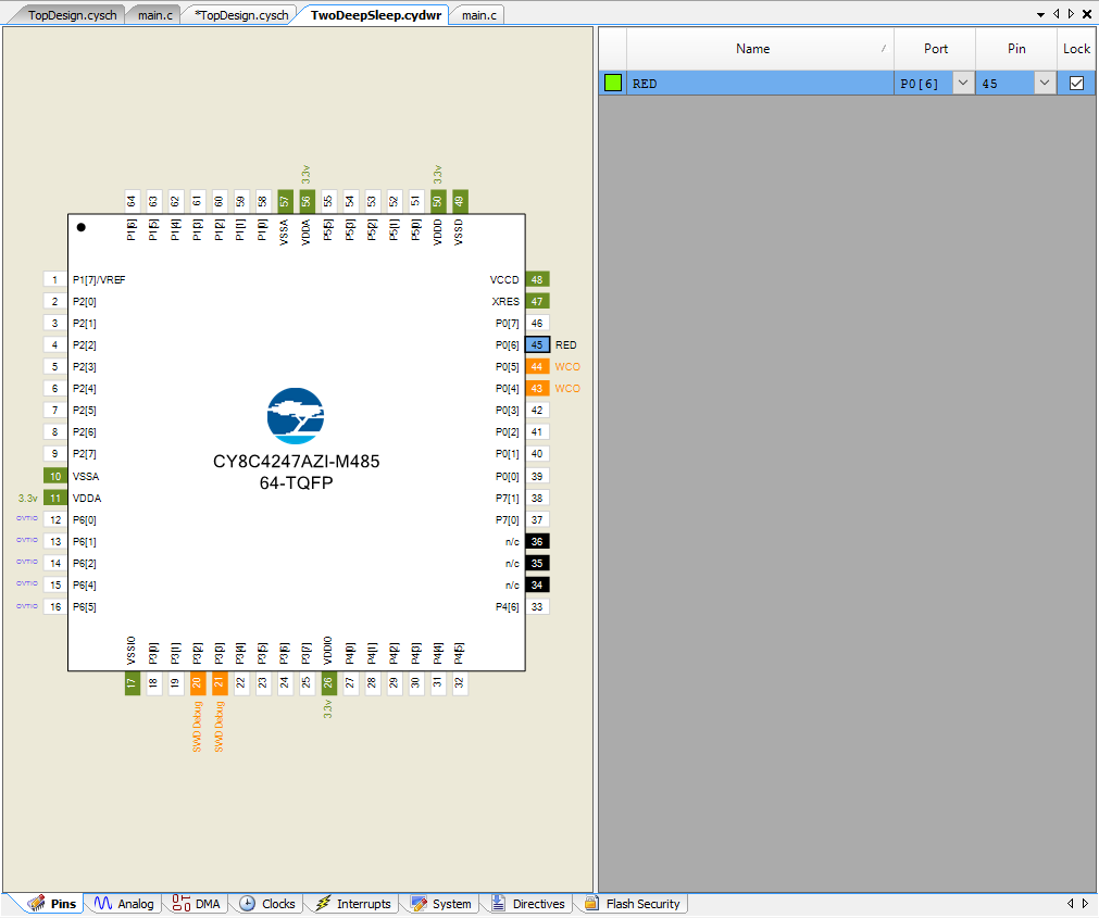
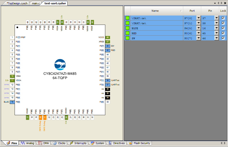
The pin assignment has the UART attached to the KitProg UART, the I2C attached to KitProg and the Display. The SCRUART is attached to UART on the Display.
Main Event Loop
The main event loop has the following parts
- Read a character from the keyboard
- Process the keyboard command character
- Read data from the screen
- If you are in packet mode read a whole packet
- If you are in streaming mode read one byte
There are three system modes.
- IDLE = Dont read from the screen
- PACKET = Read whole packets (poll for complete packets)
- STREAMING = read bytes (polling)
I also have setup the program to read/write bytes to the UART and I2C. This is called the “comInterface”.
The enumerated type systemMode is used to setup the polling mode (each time through the main loop, what does it do?).
typedef enum {
    MODE_IDLE,
    MODE_PACKET,
    MODE_STREAMING
} systemMode_t;

systemMode_t systemMode=MODE_IDLE;

typedef enum {
    INTERFACE_I2C,
    INTERFACE_UART
} cominterface_t;

cominterface_t comInterface=INTERFACE_I2C;
The actual main section of the code
- Starts by initializing the UART, SCRUART and I2C.
- On line 299 it reads a character, then switches on the character to figure out which command the user has type.
You can see that ‘u’ and ‘U’ change the communication interface from UART to I2C and back.
int main(void)
{
    CyGlobalIntEnable; /* Enable global interrupts. */
    uint32 returncode;

    UART_Start();
    UART_UartPutString("Started\r\n");
    I2C_Start();
    SCRUART_Start();

    char c;

    for(;;)
    {
        c = UART_UartGetChar();
        switch(c)
        {
            case 0:
            break;

            case 'u':
                UART_UartPutString("I2C Mode\r\n");
                comInterface = INTERFACE_I2C;
            break;

            case 'U':
                UART_UartPutString("UART Mode\r\n");
                comInterface = INTERFACE_UART;
            break;
The end of the loop handles the “?” case… in other words print out all of the commands. Then based on the system mode, it either reads a whole message packet from the display or it reads only byte.
           case '?':
                UART_UartPutString("------Communication Mode------\r\n");
                UART_UartPutString("u\tI2C Mode\r\n");
                UART_UartPutString("U\tUART Mode\r\n");

                UART_UartPutString("------GTT43A Commands------\r\n");
                UART_UartPutString("N\tDefault Comm None\r\n");
                UART_UartPutString("I\tDefault Comm I2C\r\n");
                UART_UartPutString("S\tDefault Comm Serial\r\n");

                UART_UartPutString("e\tEcho abc\r\n");
                UART_UartPutString("R\tReset\r\n");
                UART_UartPutString("c\tSend Clear Screen\r\n");

                UART_UartPutString("------Communcation Commands------\r\n");
                UART_UartPutString("r\tRead one byte if IDLE\r\n");
                UART_UartPutString("p\tRead Packet if IDLE\r\n");

                UART_UartPutString("------System Mode------\r\n");
                UART_UartPutString("0\tTurn I2C polling off \r\n");
                UART_UartPutString("1\tTurn on I2C packet polling\r\n");
                UART_UartPutString("2\tRead i2c bytes \r\n");

                UART_UartPutString("------I2C Debugging------\r\n");
                UART_UartPutString("s\tPrint SCB Status\r\n");
                UART_UartPutString("z\tSend I2C Reset Sequence\r\n");
                UART_UartPutString("x\tPrint I2C SCL and SDA value\r\n");
            break;
        }

        switch(systemMode)
        {
            case MODE_IDLE:
            break;

            case MODE_PACKET:
                readPacket();
            break;

            case MODE_STREAMING:
                readByte();
            break;
        }
I created three keys (0,1,2) to change the system mode, from IDLE, to reading whole packets to reading bytes.
            // System Modes
            case '0':
                    I2CFAIL_Write(0);
                    UART_UartPutString("Packet Poling Off\r\n");
                    systemMode = MODE_IDLE;
                break;

            case '1':
                    I2CFAIL_Write(0);
                    UART_UartPutString("Packet Poling On\r\n");
                    systemMode = MODE_PACKET;
            break;
            case '2':
                    I2CFAIL_Write(0);
                    UART_UartPutString("Read continuous\r\n");
                    systemMode = MODE_STREAMING;
                    break;
While I was trying to figure out how things worked I wanted to be able to do one thing at a time. So I create ‘r’ to read one byte (like Bridge Control Panel) and ‘p’ to read a whole packet. Notice that you really really only want to do this why you are not polling the display.
            // If you are IDLE you can read 1 byte with 'r' or read a whole packet with 'p'
            case 'r':  // Read byte
                if(systemMode != MODE_IDLE)
                    break;
                readByte(&data);

            break;
            case 'p': // read packet
                if(systemMode == MODE_IDLE)
                    readPacketI2C();
            break;
The last section of commands send various GTT2.0 commands to the display. Notice that the writePacket function knows which system interface to use (either I2C or UART).
First, I declare some commands, just an array of bytes.
// These commands come the GTT 2.0 and GTT2.5 Protocol Manuals
uint8 clearCMD[] = { 0x58 };
uint8 resetCMD[] = { 0x01};
uint8 comI2CCMD[] = { 0x05, 0x02};
uint8 comNONECMD[] = { 0x05, 0x00};
uint8 comSERIALCMD[] = { 0x05, 0x01};
uint8 comECHOCMD[] = {0xFF,'a','b','c', 0};
Then I use them:
            case 'e':
                UART_UartPutString("Send Echo Command\r\n");
                writePacket(sizeof(comECHOCMD) , comECHOCMD);
            break;

            case 'c':
                UART_UartPutString("Sent Clear String\r\n");
                writePacket(sizeof(clearCMD),clearCMD);
            break;
            case 'R':
                UART_UartPutString("Sent Reset String\r\n");
                writePacket(sizeof(resetCMD),resetCMD);
            break;
            case 'I':
                UART_UartPutString("I2C Communcation Channel\r\n");
                writePacket(sizeof(comI2CCMD),comI2CCMD);
            break;
            case 'N':
                UART_UartPutString("NONE Communcation Channel\r\n");
                writePacket(sizeof(comNONECMD),comNONECMD);
            break;
Read Byte
In order to read one byte from the display I first determine which mode Im in, then call the appropriate sub-function.
uint32_t readByte(uint8_t *data)
{
    uint32_t returncode=0;
    switch(comInterface)
    {
        case INTERFACE_I2C:
            returncode = readByteI2C(data);
        break;
        case INTERFACE_UART:
            returncode = readByteUART(data);
        break;
    }
    sprintf(buff,"Returncode = %X Data=%d\r\n",(unsigned int)returncode,*data);
    UART_UartPutString(buff);

    return returncode;
}
The first sub function to read bytes via I2C. To read a byte with no error checking you have to
- Send a Start
- Send the address
- Send the Read bit
- Clock it 8 times (this is exactly what the I2CMasterReadByte function does)
- Send an NAK
- Send a Stop
I ran into an I2C issue which I will talk about in the next article, however, if I see an error from any of these commands Ill put the system into MODE_IDLE and throw an error. In addition I write a 1 to the I2CFAIL pin, which I am using to trigger the Oscilliscope (so I can see what is happening)
uint32_t readByteI2C(uint8_t *data)
{
    uint32 returncode;
    returncode = I2C_I2CMasterSendStart(I2CADDR,I2C_I2C_READ_XFER_MODE , I2CTIMEOUT);
    if(returncode)
    {
        sprintf(buff,"send start error %lX status %lX\r\n",returncode,I2C_I2CMasterStatus());
        UART_UartPutString(buff);
        I2CFAIL_Write(1);
        systemMode = MODE_IDLE;
        goto cnt;
    }

    returncode = I2C_I2CMasterReadByte(I2C_I2C_ACK_DATA,data,I2CTIMEOUT);
    if(returncode)
    {
        sprintf(buff,"read byte error %lX status %lX sda=%d scl =%d\r\n",returncode,I2C_I2CMasterStatus(),I2C_sda_Read(),I2C_scl_Read());
        UART_UartPutString(buff);
        I2CFAIL_Write(1);
        systemMode = MODE_IDLE;
        goto cnt;
    }

    returncode = I2C_I2CMasterSendStop(I2CTIMEOUT);
    if(returncode)
    {
        sprintf(buff,"send stop error %lX status %lX\r\n",returncode,I2C_I2CMasterStatus());
        UART_UartPutString(buff);
        I2CFAIL_Write(1);
        systemMode = MODE_IDLE;
        goto cnt;
    }

    cnt:
    return returncode;
}
Read Packet
For the packet read code I did the same thing as the byte read code. Specifically I wrote an overall get packet, then called the correct read packet based on the
If you read the source code that Matrix Orbital gives you for drivers, you will find that it reads one byte at a time. The problem with doing this is that you
- Send a start
- Send an I2C address
- Send a read bit
- Read the ACK
- Read a byte
- Send a NAK
- Send a stop
The problem with this approach is that it uses 11 bit-times extra per byte of overhead (steps 1-4) which kinda sucks. So I wanted to write a complete packet reader. My packet reader will
- Send a start
- Send an I2C address
- Send a read bit
- Read the ACK
- Read a byte [This is the 254 that marks the start of the packet]
- ACK
- Read a byte [This is the command which identifies the packet]
- ACK
- Read a byte [The MSB of the Length]
- ACK
- Read a byte [The LSB of the Length]
- NAK
- If there is a length then:
- Send the start
- Send an I2C address
- Send a read bit
- Read the ACK
- read length -1 bytes
- ACK
- Read the last byte
- Send a NAK
- Send a stop
By spec you are supposed to NAK your last read byte to indicate that your read transaction is over… that means you have to NAK the last Length byte because there could be 0 bytes to read, in which case you would need to stop. It would have been nice if the protocol let you send only one start, but Im pretty sure it was designed for UART, which doesn’t suffer from this problem. Also as a side note, Im pretty sure that the MCU they are using doesn’t really care, but Im not willing to implement it incorrectly.
Here is the code:
void readPacketI2C()
{
    int length;
    int command;
    uint8_t data;
    uint32_t returncode;

    returncode = I2C_I2CMasterSendStart(I2CADDR,I2C_I2C_READ_XFER_MODE , I2CTIMEOUT);
    returncode |= I2C_I2CMasterReadByte(I2C_I2C_NAK_DATA,&data,I2CTIMEOUT);
    returncode |= I2C_I2CMasterSendStop(I2CTIMEOUT);

    // Something bad happened on the I2C Bus ....
    if(returncode)
    {
        systemMode = MODE_IDLE;
        sprintf(buff,"I2C Return Code %X\r\n",(unsigned int)returncode);
        UART_UartPutString(buff);
    }

    // The screen returns a 0 when there is nothing in the buffer.
    if(data == 0)
    {
        return;
    }

    // This is bad because there was something other than a packet start byte
    if(data != 252)
    {
        sprintf(buff,"bad data = %d\r\n",data);
        UART_UartPutString(buff);
        systemMode = MODE_IDLE; // put it into nothing mode...
        return;
    }

    // We know that we have a command
    returncode = I2C_I2CMasterSendStart(I2CADDR,I2C_I2C_READ_XFER_MODE , I2CTIMEOUT);
    returncode |= I2C_I2CMasterReadByte(I2C_I2C_ACK_DATA,&data,I2CTIMEOUT); // command
    command = data;

    returncode |= I2C_I2CMasterReadByte(I2C_I2C_ACK_DATA,&data,I2CTIMEOUT); // length
    length = data<<8;
    returncode |= I2C_I2CMasterReadByte(I2C_I2C_NAK_DATA,&data,I2CTIMEOUT); // length
    length = length + data;
    returncode |= I2C_I2CMasterSendStop(I2CTIMEOUT);

    // If the packet has any data... then read it.
    if(length != 0)
    {
        returncode |= I2C_I2CMasterSendStart(I2CADDR,I2C_I2C_READ_XFER_MODE , I2CTIMEOUT);

        for(int i=0;i<length-1; i++)
        {
            I2C_I2CMasterReadByte(I2C_I2C_ACK_DATA,&data,I2CTIMEOUT); // length
            inbuff[i] = data;
        }

        // Read the last byte
        I2C_I2CMasterReadByte(I2C_I2C_NAK_DATA,&data,I2CTIMEOUT); // length
        inbuff[length-1] = data;
        returncode |= I2C_I2CMasterSendStop(I2CTIMEOUT);

        I2C_I2CMasterSendStop(I2CTIMEOUT);
    }

    sprintf(buff,"command = %d length = %d bytes= ",command,length);
    UART_UartPutString(buff);
    for(int i=0;i<length;i++)
    {
        sprintf(buff,"%d ",inbuff[i]);
        UART_UartPutString(buff);
    }
    UART_UartPutString("\r\n");

}
You can "git" these projects from https://github.com/iotexpert/GTT43A And the driver library from https://github.com/iotexpert/GTT-Client-Library
Title
Matrix Orbital GTT43: A Cool Display
Matrix Orbital GTT43A: Serial Interface
Matrix Orbital GTT43A: GTT Scripts
Matrix Orbital GTT43A: A PSoC 4 Interface
Matrix Orbital GTT43A: Debugging the I2C
Matrix Orbital GTT43A: GTT Driver Library - Part 1
Matrix Orbital GTT43A: GTT Driver Library - Part 1
Matrix Orbital GTT43A: PSoC 6 using RTOS and the GTT Driver Library
