Summary
I have gotten quite a few questions about my PSoC FreeRTOS series of Articles. One question was: “I have a bunch of different I2C sensors, what is a good PSoC FreeRTOS scheme to share the I2C bus?” When I thought about this question there were a number of possible firmware architectures that could be used:
- Each sensor has a thread, and there is a global Mutex to lock/unlock the I2C bus
- There is single thread that reads and writes to all of the sensors (oh…wait… that looks like the old bare metal while(1); )
- There is a single I2C thread that can take requests execute them, and then feed data back to the calling thread
After thinking about it a bit, I decided to use the 3rd scheme as it allows me to
- Reuse the I2C interface code (all the sensors have a register map that you read/write)
- Handle all of the timing issues in one place (instead of duplicated)
- Isolate the I2C interface from all of the threads (could be replaced with SPI or something else later)
In this article I will show you:
- The register based I2C interface that is in common use with sensors
- The design of the PSoC FreeRTOS firmware with a single I2C interface thread
- The PSoC FreeRTOS firmware implementation
- A test case using the CY8CKIT-044
Interfacing with I2C Sensor Registers using PSoC FreeRTOS
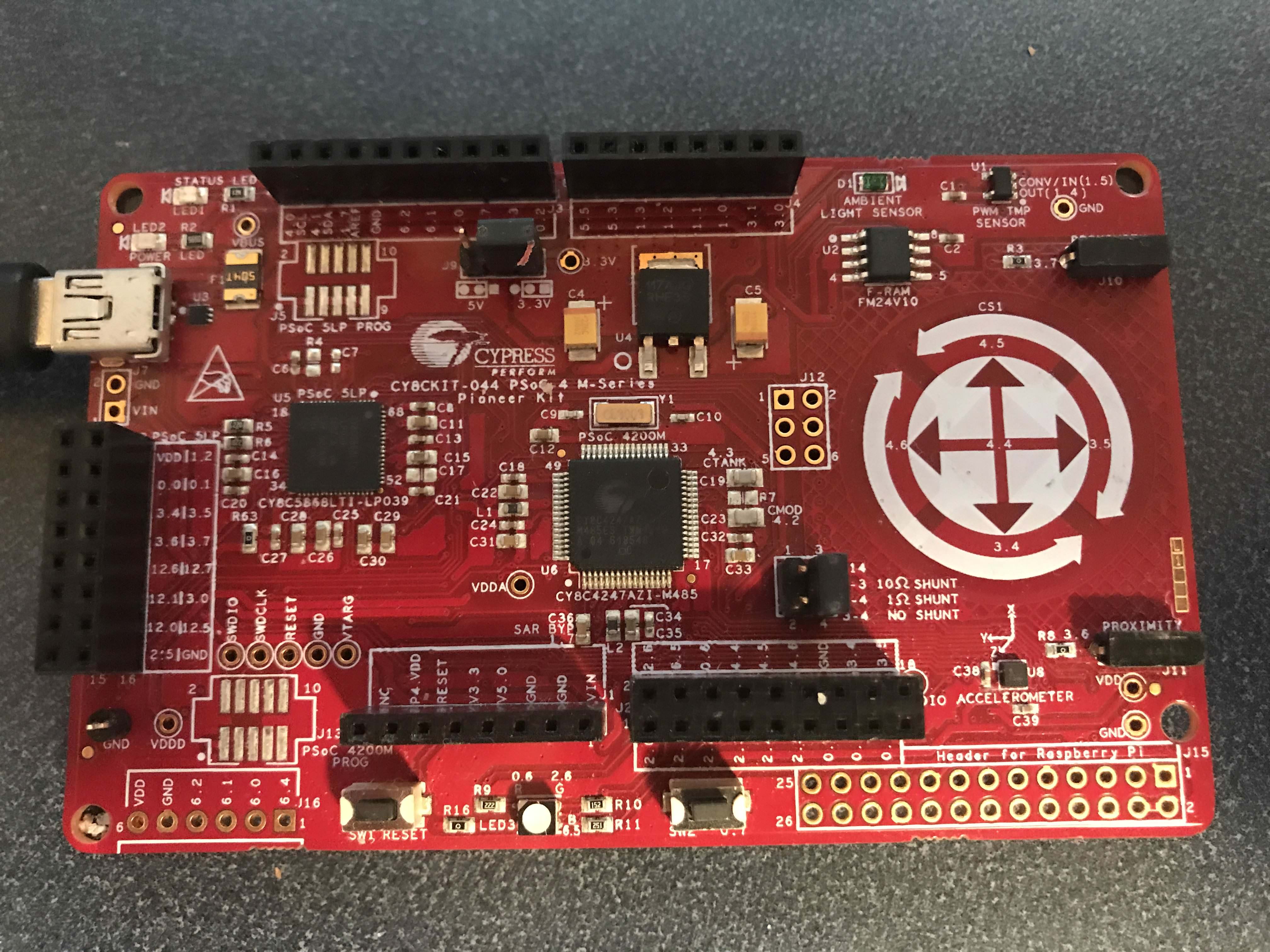
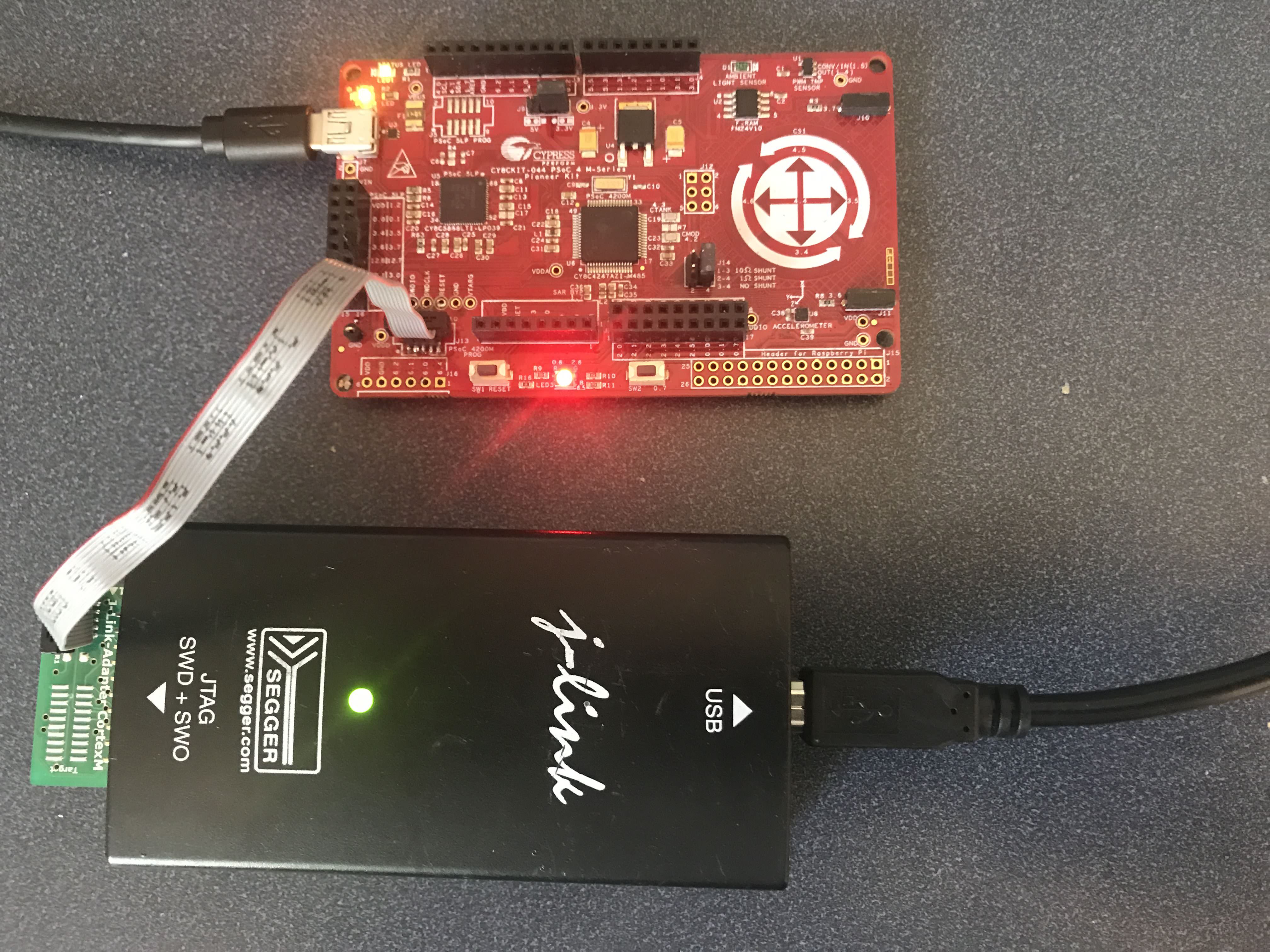
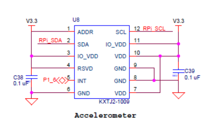
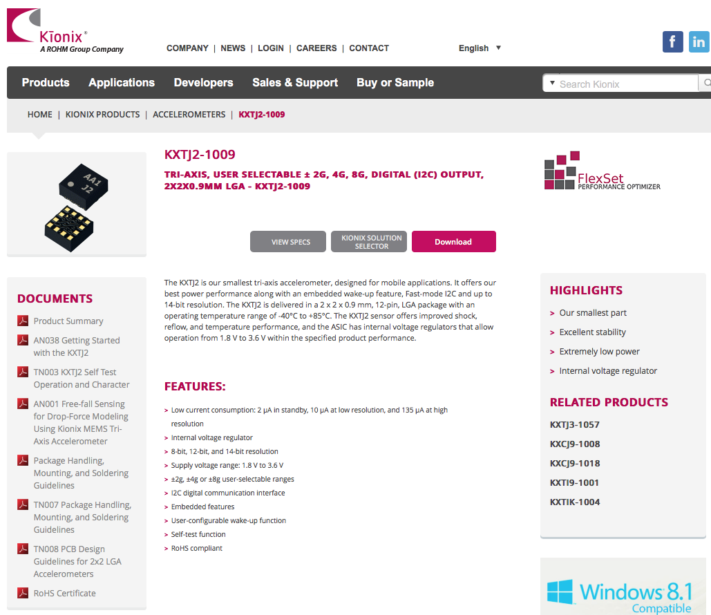
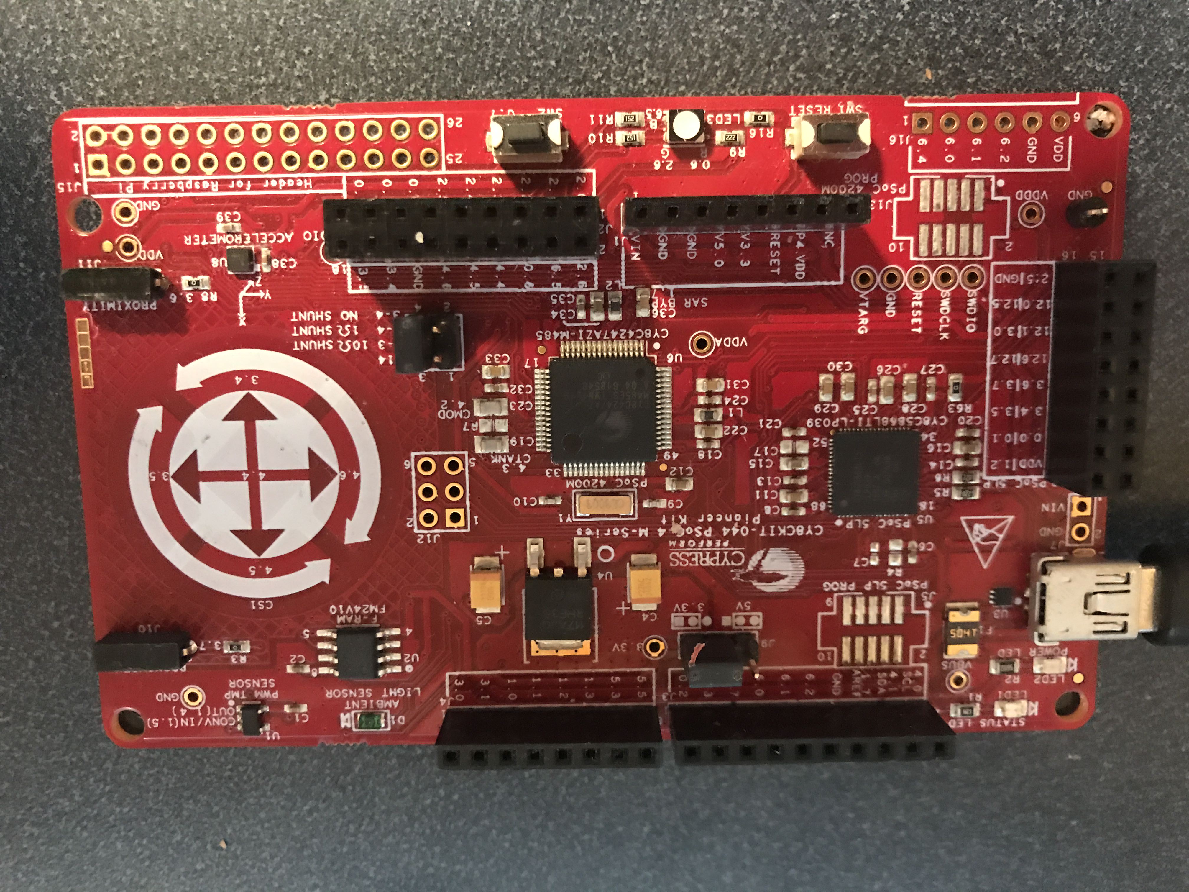
The CY8CKIT-044 (on of my favorite Cypress kits) has two devices attached to the I2C bus, so it made a perfect test platform. On the front there is a Cypress FM24V10 FRAM and a Kionix KXTJ2-1009 I2C Accelerometer.
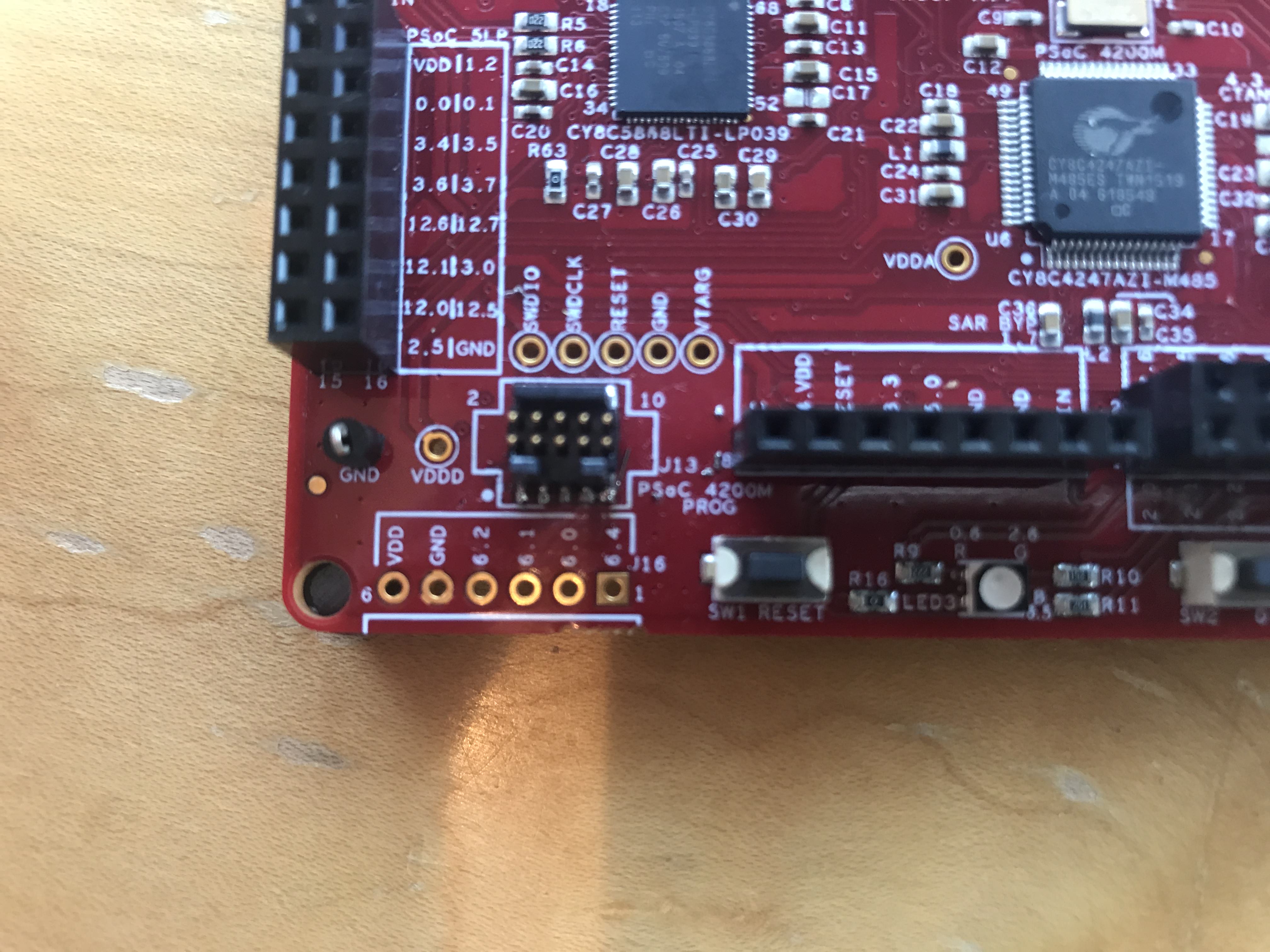
And on the back there is a nice little picture on the silkscreen that gives the FRAM I2C Address as 0x50, the I2C Address of the Accelerometer as 0X0F and the I2C pins as P4.0/P4.1 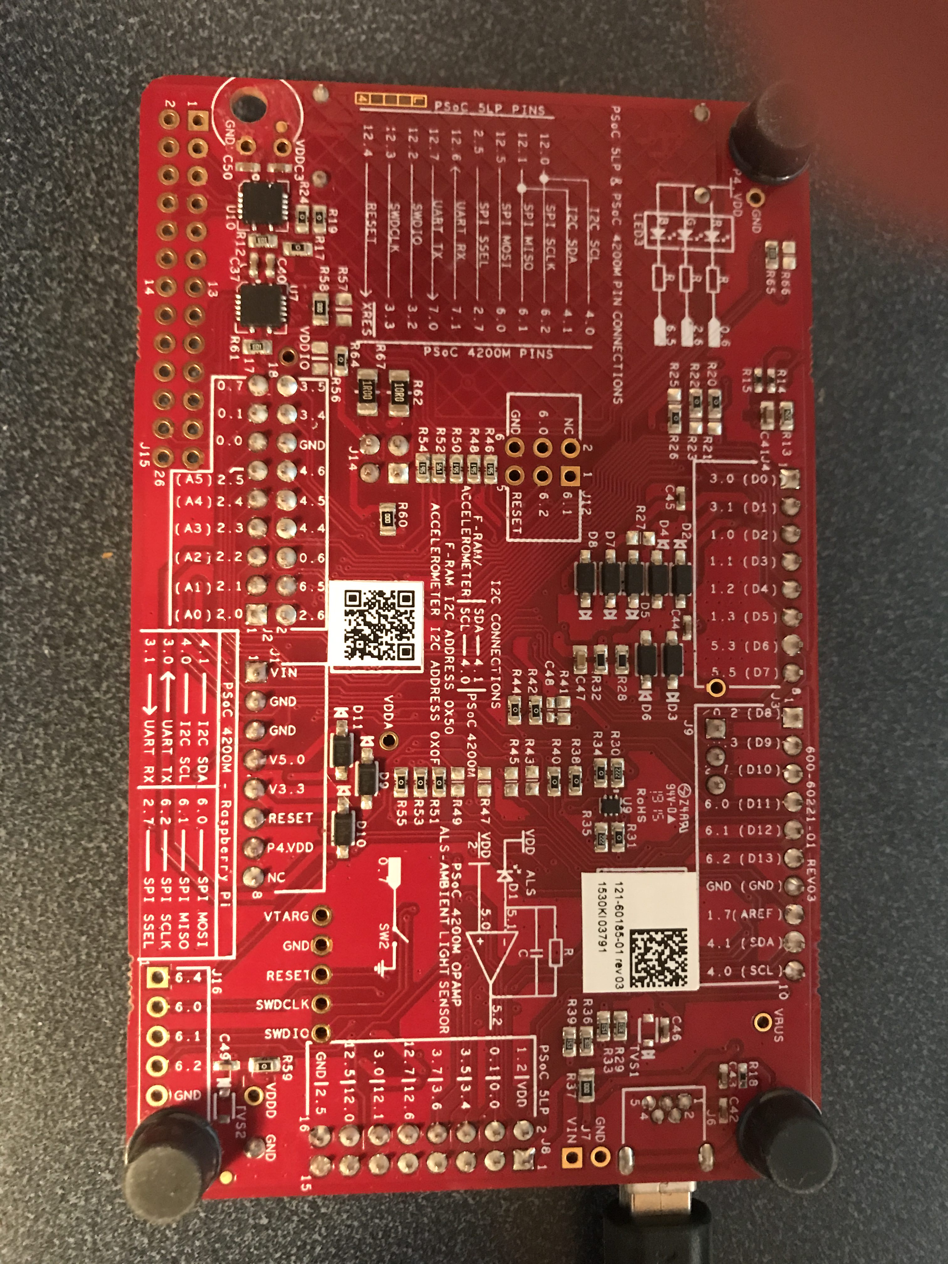
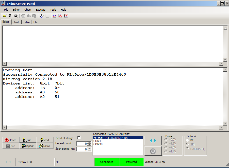
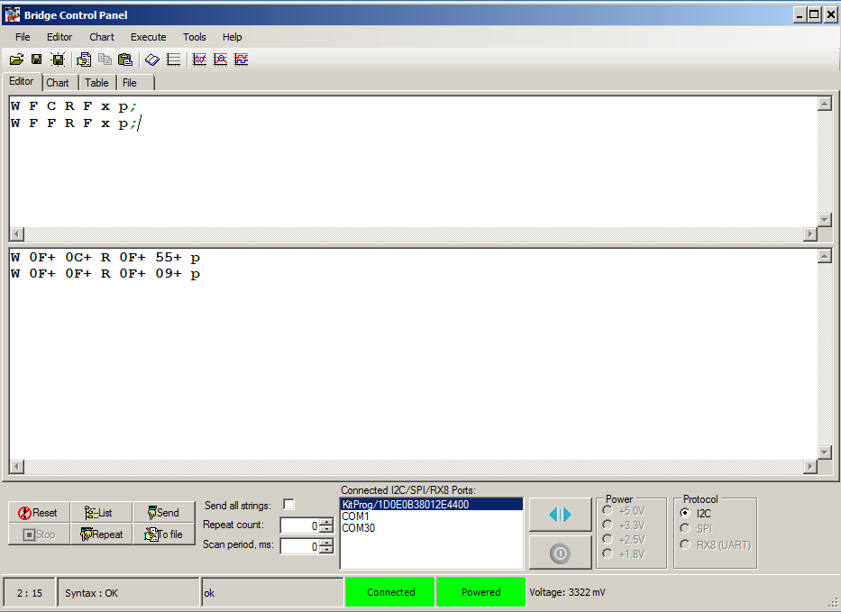
When I probe the I2C Bus using the bridge control panel I see that three I2C devices respond, 0x0F (the KXTJ2-1009), 0x50/0x51 (the FRAM.)
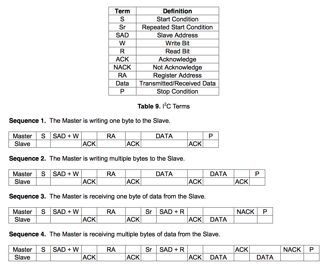
So, how do you talk to the devices? It turns out that both of these devices respond to the very common I2C device scheme which is called “EZI2C” inside of Cypress. The scheme goes like this:
- The chip is organized into registers
- Each register has an address
- Addresses are either 8-bits or 16-bits
- To write an address you can send a string of bytes like: I2C Start, I2C Address + W, Register Address, Value to write, Stop
- To read an address you can send a string of bytes like: I2C Start, I2C Address + W, Register Address, Restart, Read, Stop
A simplification is that you can keep writing (or reading) and it will automatically goes to the next address without you having to send the next address. The easiest thing to do is show an example with the FRAM.
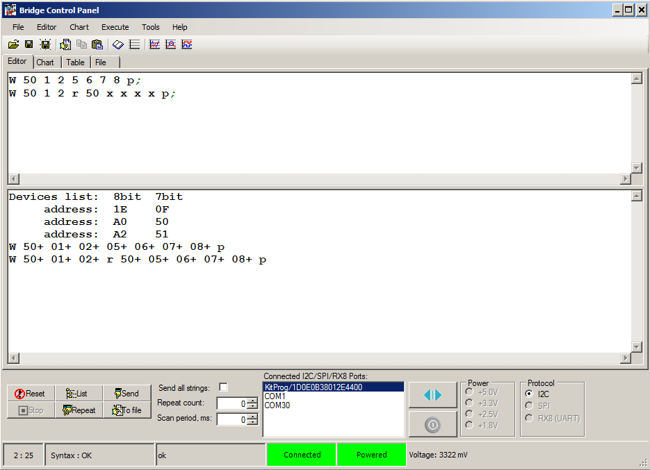
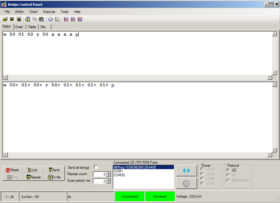
The FRAM has 128K addresses so it uses 16-bit addresses. For example to save the values 5,6,7,8 into the register 0x0123 you would send:
- 0x50, W, 0x01, 0x02, 0x05, 0x06, 0x07, 0x08, Stop (in the bridge control panel the command is W 50 1 2 5 6 7 8 p)
To read back those addresses you would send
- 0x50, W, 0x01, 0x02, restart, read read read read Stop (in the bridge control panel the command is W 50 1 2 R 50 x x x x p)
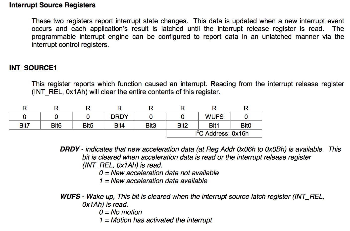
The interface is similar for the Kionix KXTJ2-1009. When you look at the datasheet you will see on page 17 their description of the EZI2C protocol:
Then on page 20 they start describing the registers, and on page 21 they describe two registers (called DCST_RESP and WHO_AM_I) that will always respond with known values.
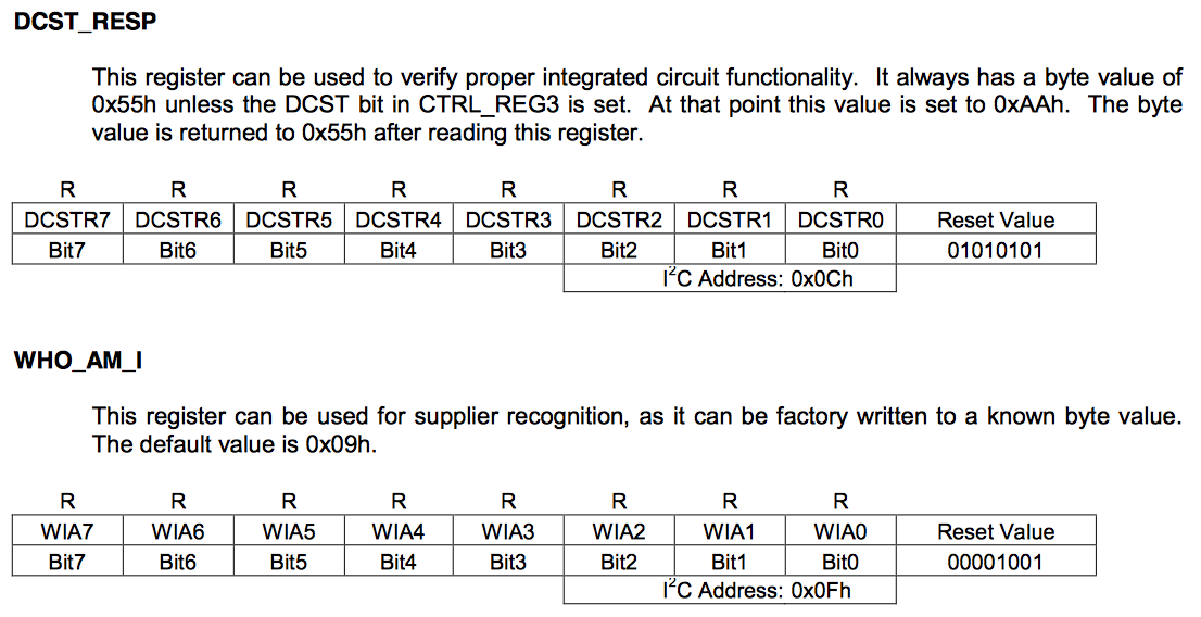
To verify the operation I send read commands using the Bridge Control panel to those registers, which respond with 55 and 9 just like the datasheet says that they should.
Designing PSoC FreeRTOS FW for I2C Register Based Sensors
From the previous section(s) we know that
- Two totally different devices, a memory and an accelerometer, can be accessed using exactly the same protocol
- It may take a while to complete I2C transactions (4 bytes @ 400kb/s = 87.5uS).
- The I2C master is a “shared” interface on the board, but multiple threads may want to perform transactions
These facts lead up to the conclusion that it would be nice to:
- Have a standard software interface to I2C devices that use the EZI2C protocol
- Have a non-blocking thread to run the interface
- Share the I2C
- Use PSoC FreeRTOS (the whole point)
With all of that in mind I created “i2cmaster.h”, the public interface to a PSoC FreeRTOS thread that will run the EZI2C protocol. It defines two public functions
- i2cm_Task – The thread that will need to be started to run all of the transactions
- i2cm_runTransaction – The thread safe public interface which will send the transaction to the i2cm_Task
To run a transaction you need to have a transaction. I defined a new type called “i2cm_transaction”. This type is a structure that contains all of the information that is required to perform a transaction. The input is split into three sections:
- The I2C Address, the Register Address (and type 8-bit or 16-bit), and if the transaction is a Read or a Write
- The number of bytes you want to read/write and a pointer to the data
- The number of bytes that were processed (an output of the task)… plus an optional semaphore that will be given if you want a blocking transaction
#include <project.h>
#include "FreeRTOS.h"
#include "semphr.h"

#ifndef I2C_MASTER_H
#define I2C_MASTER_H


typedef enum i2cm_transactionMethod {
    I2CM_READ,
    I2CM_WRITE
} i2cm_transactionMethod_t;

typedef enum i2cm_registerAddresType {
    I2CM_BIT8,
    I2CM_BIT16

} i2cm_registerAddressType_t;


typedef struct i2cm_transaction {
    i2cm_transactionMethod_t i2cm_method;        // I2CM_READ or I2CM_WRITE
    uint8_t i2cm_address;                        // The I2C Address of the slave
    i2cm_registerAddressType_t i2cm_regType;     // I2CM_8BIT or I2CM_16BIT
    uint16_t i2cm_register;                      // The register in the slave

    uint8_t *i2cm_bytes;                         // A pointer to the data to be written (or a place to save the data)
    int i2cm_byteNum;                            // How many bytes are in the request

    int *i2cm_bytesProcessed;                    // A return value with the number of bytes written
    SemaphoreHandle_t i2cm_doneSemaphore;        // If you want a semaphore flaging that the transaction is done

} i2cm_transaction_t;

void i2m_Task(void *arg);                  // The main thread function... you should start it in the RTOS

void i2cm_runTransaction(i2cm_transaction_t *i2cm_Transaction); // The public interface

#endif
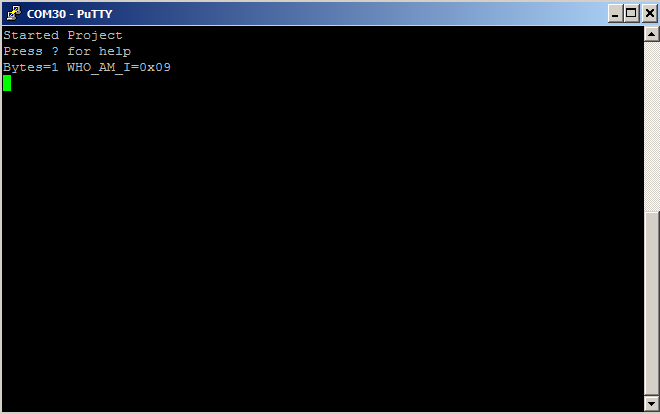
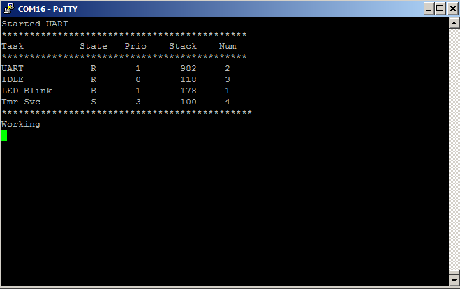
With the public interface setup you will be able to run code that does exactly the same thing as you did in the bridge control panel. For instance you can query the accelerometer “WHO_AM_I” register:
                    mytransaction.i2cm_method = I2CM_READ;
                    mytransaction.i2cm_address = 0x0F;            // Acelleromter I2C Address
                    mytransaction.i2cm_regType = I2CM_BIT8;       // 8-bit addressing
                    mytransaction.i2cm_register = 0x0F;           // WHO_AM_I Register

                    mytransaction.i2cm_byteNum = 1;               // One byte
                    mytransaction.i2cm_bytes = data;

                    mytransaction.i2cm_bytesProcessed = &byteCount;
                    mytransaction.i2cm_doneSemaphore = mySemaphore;
                    i2cm_runTransaction(&mytransaction);

                    sprintf(buff,"Bytes=%d WHO_AM_I=0x%02X\n",byteCount,data[0]);
                    UART_UartPutString(buff);
Which will yield exactly the same result as the bridge control panel did:
Implementing a PSoC FreeRTOS I2C Master Library
From the previous section we know the public interface. But how does it work? When the PSoC FreeRTOS i2cm_Task starts it:
- Starts up the hardware I2C block
- It makes a queue. The queue will hold transactions which are waiting to be processed. This is how multiple processes will put requested transactions into the queue, and the I2C master will deal with them one at a time in the order they were placed in the queue.
- It starts up the infinite loop and waits for a transaction to be placed in the queue.
void i2cm_Task(void *arg)
{

    // The argument is the size of the queue
    uint32_t queueSize = (uint32_t)arg; // cast the arg

    I2C_Start(); // turn on the I2C Master

    i2cm_transaction_t i2cm_transaction; // A scratch transaction
    i2cm_transactionQueue = xQueueCreate(queueSize, sizeof(i2cm_transaction_t));

    uint32_t rval; // all of the I2C functions return a uint32_t

    while(1)
    {
        int i;

        // Wait until something gets put in the queue
        if(xQueueReceive(i2cm_transactionQueue,&i2cm_transaction,portMAX_DELAY) == pdTRUE)
The public interface to the whole system is i2cm_runTransaction. It takes the transaction structure and pushes it onto the queue for the main thread to process. If the user has asked to wait for completion then it also holds until the semaphore is given by the main loop.
// the i2cm_runTransaction function is the public interace to the system
// This function is thread safe (it can be called from any thread)
// It will queue up an I2C tranaction and then wait (if there is a semaphore handle)
void i2cm_runTransaction(i2cm_transaction_t *i2cm_transaction)
{
    if(xQueueSend(i2cm_transactionQueue,i2cm_transaction,portMAX_DELAY) != pdTRUE)
    {
        // Highly bad
        CYASSERT(0); //
    }
    if(i2cm_transaction->i2cm_doneSemaphore)
        xSemaphoreTake(i2cm_transaction->i2cm_doneSemaphore,portMAX_DELAY);
}
The last part of the system is the main transaction processing loop which:
- Waits for a transaction
- Sends a start, then write the I2C address and register address (lines 65-75)
- If it is a write, then write the bytes (lines 80-85)
- If it is a read, then read then read bytes (lines 89-102)
- Send a stop (lines 105-106)
- If the user asked for a semaphore, give it. (lines 112-113)
        // Wait until something gets put in the queue
        if(xQueueReceive(i2cm_transactionQueue,&i2cm_transaction,portMAX_DELAY) == pdTRUE)
        {
            // Begining of an I2C transaction
            *i2cm_transaction.i2cm_bytesProcessed = 0;
            // First write the register address
            rval = I2C_I2CMasterSendStart(i2cm_transaction.i2cm_address,I2C_I2C_WRITE_XFER_MODE);
            if(rval != I2C_I2C_MSTR_NO_ERROR) goto cleanup;

            if(i2cm_transaction.i2cm_regType == I2CM_BIT16) // if a 16 bit register then send the high
            {
                rval = I2C_I2CMasterWriteByte((i2cm_transaction.i2cm_register >> 8) & 0xFF);
                if(rval != I2C_I2C_MSTR_NO_ERROR) goto cleanup;
            }
            rval = I2C_I2CMasterWriteByte((i2cm_transaction.i2cm_register ) & 0xFF); // send the low byte
            if(rval != I2C_I2C_MSTR_NO_ERROR) goto cleanup;

            // if w send ...
            switch(i2cm_transaction.i2cm_method) // Look at the type of transaction they want to do...
            {
                case I2CM_WRITE:  // If it is a write... then just send out the bytes
                for(i=0; i < i2cm_transaction.i2cm_byteNum;i++)
                {
                    rval = I2C_I2CMasterWriteByte(i2cm_transaction.i2cm_bytes[i]);
                    if(rval != I2C_I2C_MSTR_NO_ERROR) goto cleanup;
                    *i2cm_transaction.i2cm_bytesProcessed += 1;
                }
                break;

                case I2CM_READ: // If it is a read.. then do a restart with READ... then read n-1 bytes
                rval = I2C_I2CMasterSendRestart(i2cm_transaction.i2cm_address,I2C_I2C_READ_XFER_MODE);
                if(rval != I2C_I2C_MSTR_NO_ERROR) goto cleanup;
                for(i=0; i < i2cm_transaction.i2cm_byteNum-1;i++)
                {
                    i2cm_transaction.i2cm_bytes[i] = I2C_I2CMasterReadByte(I2C_I2C_ACK_DATA);
                    if(i2cm_transaction.i2cm_bytes[i] & 0x10000000) goto cleanup;
                    *i2cm_transaction.i2cm_bytesProcessed += 1;
                }
                // Then read the last byte and NAK (saying you are done)
                i2cm_transaction.i2cm_bytes[i2cm_transaction.i2cm_byteNum-1] = I2C_I2CMasterReadByte(I2C_I2C_NAK_DATA);
                if(i2cm_transaction.i2cm_bytes[i2cm_transaction.i2cm_byteNum-1] & 0x10000000) goto cleanup;
                *i2cm_transaction.i2cm_bytesProcessed += 1;
                break;
            }

            rval = I2C_I2CMasterSendStop();
            if(rval != I2C_I2C_MSTR_NO_ERROR) goto cleanup;

            cleanup:
            CYASSERT(rval == 0); // something really bad happend

           // If they ask for a semphore when done... then give it
            if(i2cm_transaction.i2cm_doneSemaphore)
                xSemaphoreGive(i2cm_transaction.i2cm_doneSemaphore);
        }
I2C Sensor Library on the CY8CKIT-044 (FRAM)
In order to test the FRAM I define a buffer in the RAM of the PSoC called “data”. Then I setup three commands that can be executed from the UART Thread which will:
- q – read 4 bytes from register 0x0102 into the data[] array
- w -write 4 bytes from the data[] array into the FRAM register 0x0102
- i – increment the values in the data[] array.
The code is simple:
           case 'q':
                    mytransaction.i2cm_address = 0x50;
                    mytransaction.i2cm_regType = I2CM_BIT16;
                    mytransaction.i2cm_byteNum = 4;
                    mytransaction.i2cm_register = 0x0102;
                    mytransaction.i2cm_method = I2CM_READ;
                    mytransaction.i2cm_bytesProcessed = &byteCount;
                    mytransaction.i2cm_bytes = data;
                    mytransaction.i2cm_doneSemaphore = mySemaphore;
                    i2cm_runTransaction(&mytransaction);
                    sprintf(buff,"Bytes=%d 0=%d 1=%d 2=%d 3=%d\n",byteCount,data[0],data[1],data[2],data[3]);
                    UART_UartPutString(buff);
            break;
            case 'i': // This will increment the values (that you read presumably from the FRAM
                    data[0] += 1;
                    data[1] += 1;
                    data[2] += 1;
                    data[3] += 1;
                    sprintf(buff,"0=%d 1=%d 2=%d 3=%d\n",data[0],data[1],data[2],data[3]);
                    UART_UartPutString(buff);
            break;

            case 'w': //This will write 4 values to register 0 in the FRAM
                    mytransaction.i2cm_address = 0x50;
                    mytransaction.i2cm_regType = I2CM_BIT16;
                    mytransaction.i2cm_byteNum = 4;
                    mytransaction.i2cm_register = 0x0102;
                    mytransaction.i2cm_method = I2CM_WRITE;
                    mytransaction.i2cm_bytesProcessed = &byteCount;
                    mytransaction.i2cm_bytes = data;
                    mytransaction.i2cm_doneSemaphore = mySemaphore;
                    i2cm_runTransaction(&mytransaction);
                    sprintf(buff,"Wrote %d bytes\n",byteCount);
                    UART_UartPutString(buff);
            break;
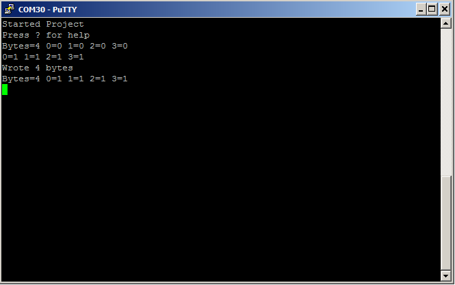
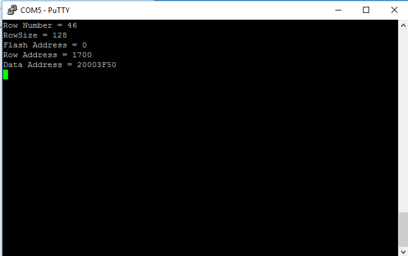
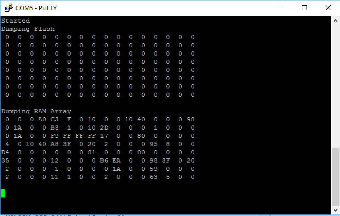
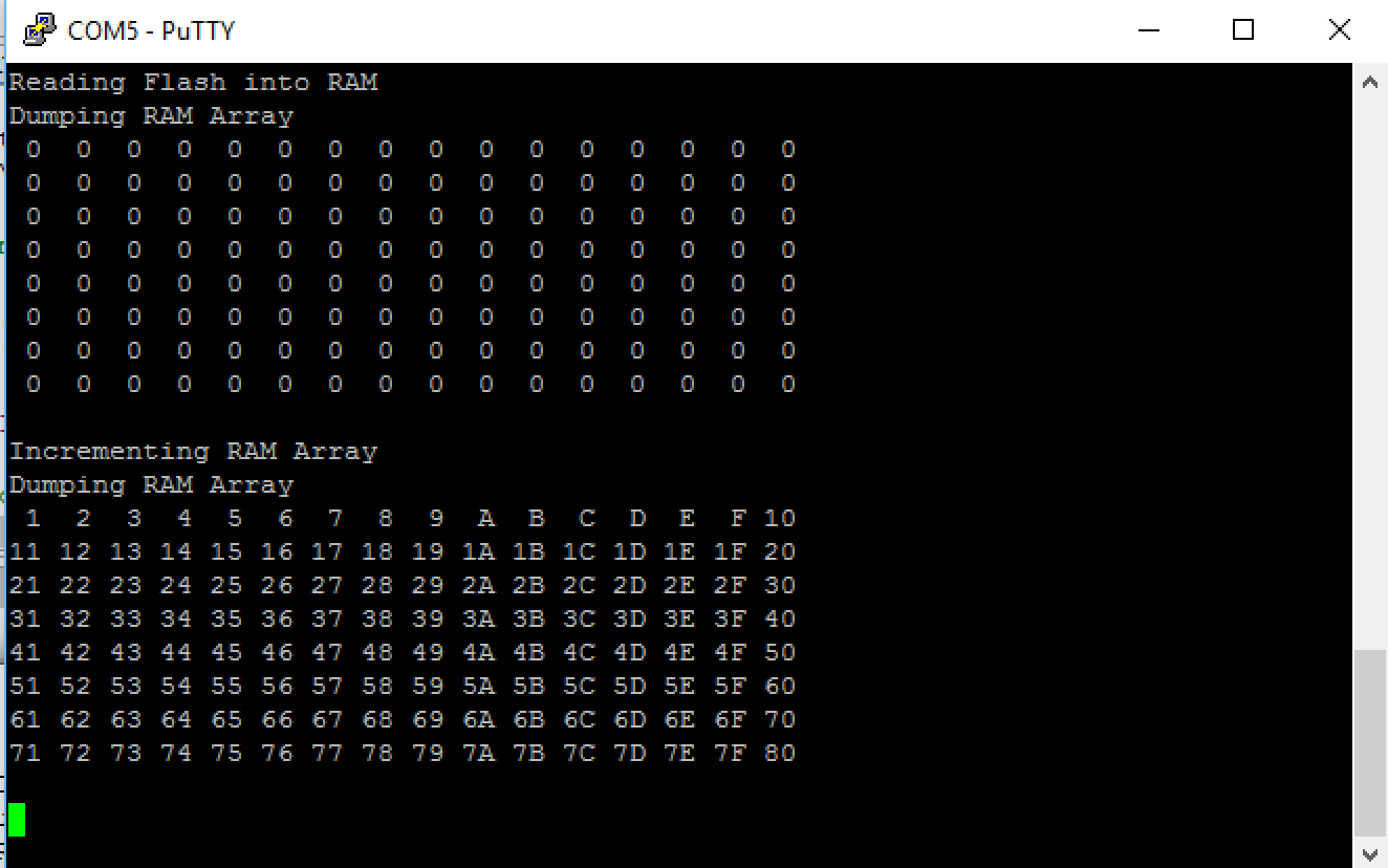
To test:
- Press ‘q’ to read from the FRAM into data[]
- Press ‘i’ to increment the values in data[]
- Press ‘w’ to write the data[] back into the FRAM
- Press ‘q’ to make sure that the values were written
- Use the bridge control panel to read the data to make sure that it is right.
I2C Sensor Library on the CY8CKIT-044 (Accelerometer)
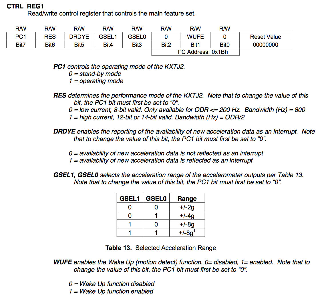
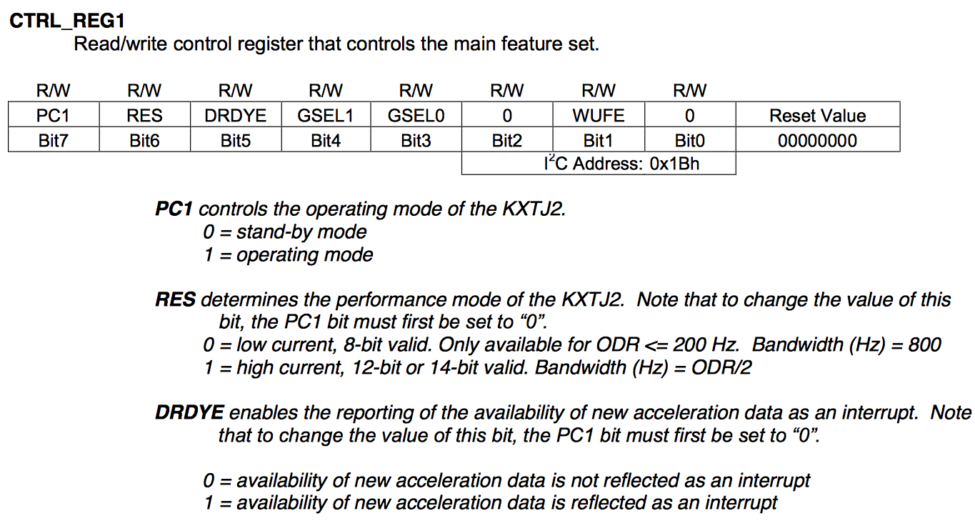
Finally, to test the Accelerometer I create a PSoC FreeRTOS thread which starts up and turns on the Accelerometer. To turn on the accelerometer you need to write a 0b1000000 to register 0x1b (called the CTRL_REG_1)
// This task manages the accelerometer
//
void accel_Task(void *arg)
{
    (void)arg;
    SemaphoreHandle_t mySemaphore;
    i2cm_transaction_t mytransaction;
    char buff[128];
    int x,y,z;
    int xs,ys,zs;

    int byteCount;
    accel_t myData;

    mySemaphore = xSemaphoreCreateBinary();

    // True of all read/writes
    mytransaction.i2cm_address = 0x0F;
    mytransaction.i2cm_regType = I2CM_BIT8;
    mytransaction.i2cm_bytesProcessed = &byteCount;

    // Initalize the acceleromter
    uint8_t setupData[] = {0b10000000};
    mytransaction.i2cm_method = I2CM_WRITE;
    mytransaction.i2cm_register = 0x1b; // CTRL_REG_1
    mytransaction.i2cm_byteNum = sizeof(setupData);
    mytransaction.i2cm_doneSemaphore = mySemaphore;
    mytransaction.i2cm_bytes = setupData;
    i2cm_runTransaction(&mytransaction);
Once the accelerometer is turned on, it will update 6 registers called XOUT_L/XOUT_H, YOUT_L/YOUT_Z, XOUT_L/ZOUT_H with the current X,Y and Z acceleration. The data will be in the form of a 12-bit signed integer, left aligned (in other words the 4 least significant bits will be nothing). I create a structure that I will use to hold the acceleration data. Notice that I used “CY_PACKED” so that it will be not padded by the compiler.
CY_PACKED typedef struct accel {
    int16_t x;
    int16_t y;
    int16_t z;
} CY_PACKED_ATTR accel_t;
Then I set up a read transaction of those registers, which are conveniently all right next to each other so you can read 6 consecutive bytes.
   // Setup for repeated reads
    mytransaction.i2cm_method = I2CM_READ;
    mytransaction.i2cm_register = 0x06;
    mytransaction.i2cm_byteNum = sizeof(myData);
    mytransaction.i2cm_doneSemaphore = mySemaphore;
    mytransaction.i2cm_bytes = (uint8_t *)&myData;
Finally I repeatedly read the registers and print out the results. The only trick is that I didn’t enable the floating point output libraries (they are huge), so I manually convert the floats to ints to be printed out.
    while(1)  // Run the same transaction over and over
    {
        i2cm_runTransaction(&mytransaction);
        myData.x /= 16;  // The KXTJ2 Datasheet say lower 4 bits are X
        myData.y /= 16;  // The KXTJ2 Datasheet say lower 4 bits are X
        myData.z /= 16;  // The KXTJ2 Datasheet say lower 4 bits are X
        xs = (myData.x < 0? -1:1);  // Find the XSign
        ys = (myData.y < 0? -1:1);  // Find the YSign
        zs = (myData.z < 0? -1:1);  // Find the ZSign

        // The 1024 is a hardcode based on the range of the acceleromter
        x = (int)((float)myData.x / 1024.0 * 10.0) * xs; // Turn it into integer G * 10
        y = (int)((float)myData.y / 1024.0 * 10.0) * ys; // Turn it into integer G * 10
        z = (int)((float)myData.z / 1024.0 * 10.0) * zs; // Turn it into integer G * 10

        // Format data in x.x
        sprintf(buff,"x=%s%d.%dg\ty=%s%d.%dg\tz=%s%d.%dg\n",(xs<0?"-":""),x/10,x%10,(ys<0?"-":""),y/10,y%10,(zs<0?"-":""),z/10,z%10);
        UART_UartPutString(buff);
        vTaskDelay(1000); // delay for 1 second
    }
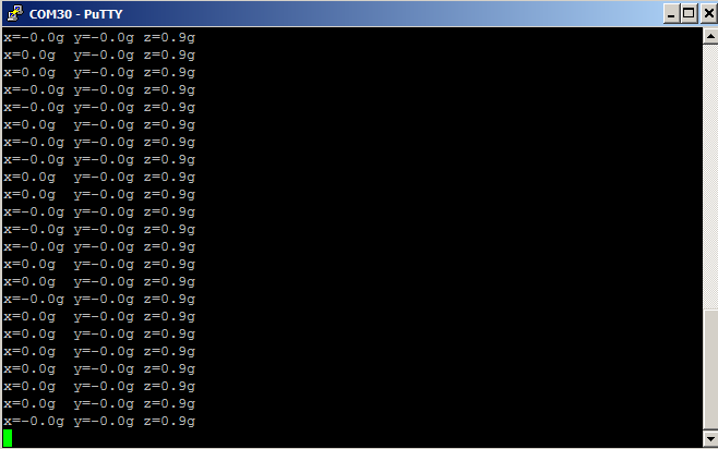
And here is the screen shot of the output of the PSoC FreeRTOS with the kit sitting on my desk…. the output is about 1G down (which make sense)
As always you can git this PSoC FreeRTOS project at the IoT Expert GitHub site or git@github.com:iotexpert/PSoC-FreeRTOS-Examples.git


