Summary
In the last Article I analyzed the performance problems of my firmware based PSoC Tracealyzer Streamport … which was terrible. Although it has been a long time since I used the PSoC4M DMA engine, I knew that it would solve my problem. In this article Ill show how to use the PSoC DMA, then Ill build and analyze a PSoC DMA Streamport for Tracealyzer.
PSoC4 UART DMA
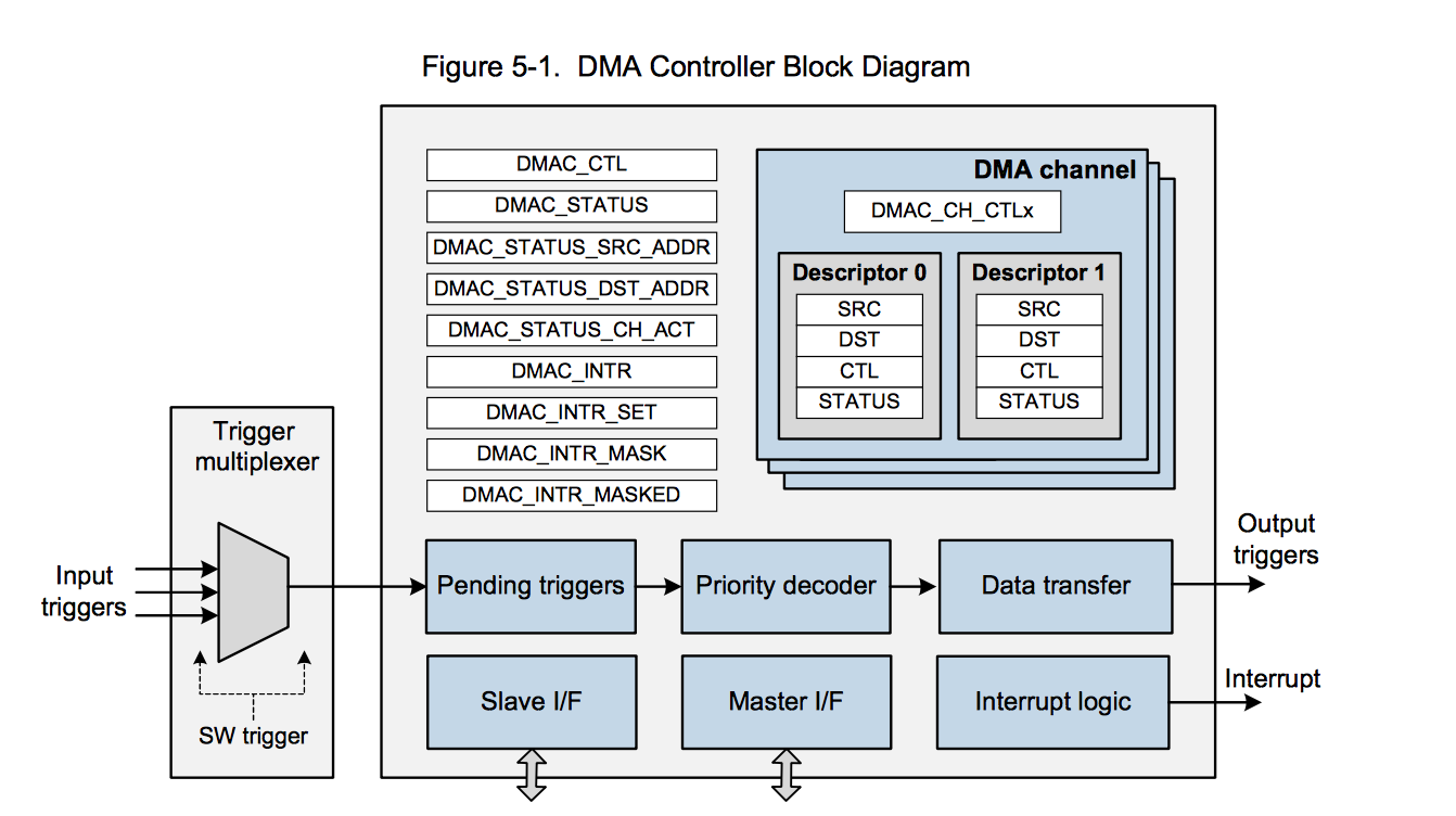
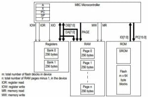
The DMA block that shows up in the PSoC4200M, PSoC 4200L and PSoC4BLE is pretty amazing. It can do a bunch of stuff. Here is a snapshot that I took out of the TRM. This block sits on the main AHB bus inside of the PSoC. It can act as a master (see the block that says Master I/F) and read and write any of things in the ARM address space including the Flash, SRAM, and all of the peripherals. It has an incoming trigger which can get the transfers going and when it is done it can trigger an interrupt or another DMA channel. The Slave I/F allows the CPU to program the block. The device has 8-channels with each channel having 2 descriptors (so it can ping pong).
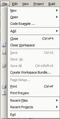
Before I tried to make the PSoC DMA Streamport I started by looking at the example projects by pressing “File->Code Example”
Then filtering for DMA
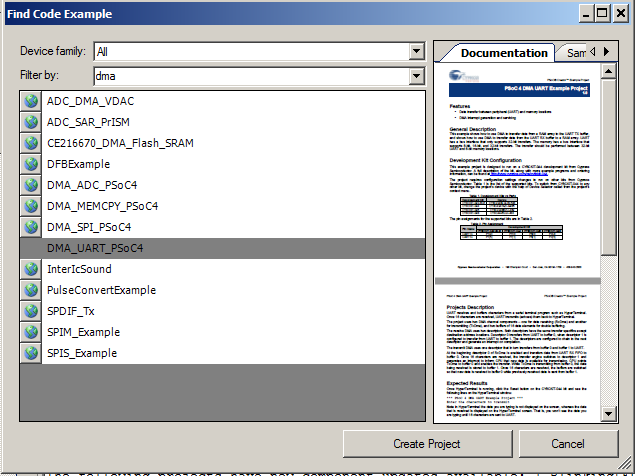
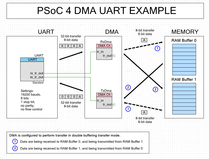
Finally creating project. This project uses two DMA channels, one for the UART receive and one for the UART Transfer. It lets you type characters into the UART, it saves them in one of the RAM buffers, then when you have typed 8, it DMAs them back into the Transmit channel of the UART. This example ping-pings back and forth between two RAM buffers.
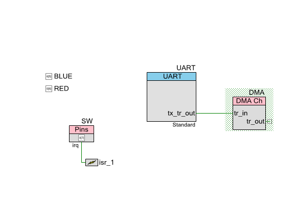
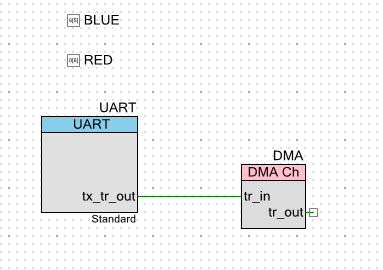
I decided that it would be best to build a bare metal DMA project called “test-uart” to prove that I understood. This project will DMA transfer an array of characters to the UART when the user presses the switch on the board or a “s” on the keyboard. The first thing to do is build the schematic with a UART, a DMA block, two output pins, and input pin and an interrupt.
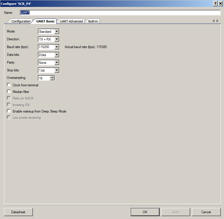
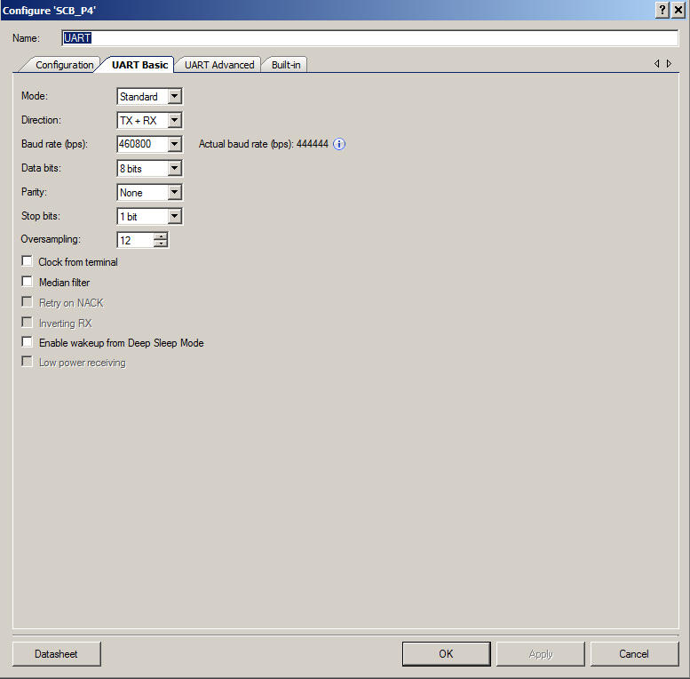
Place an SCB UART. then configure it (change the name, but accept all of the defaults)
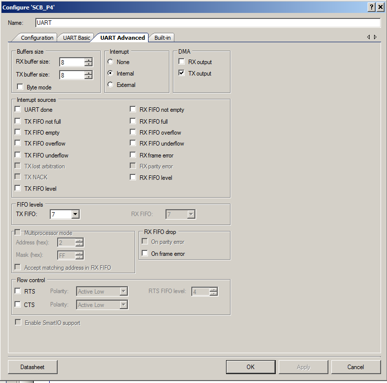
Then click on the advanced tab. Turn on the DMA for Transfer (TX Output) and set the “FIFO Level” to 7. This will cause the UART to assert DMA signal anytime the transmit FIFO has less than 7 bytes. In other words … FEED ME!!!

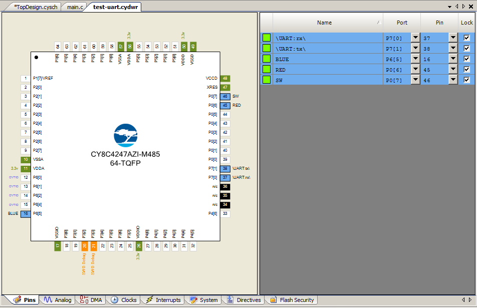
After configuring the UART, Set the PINs
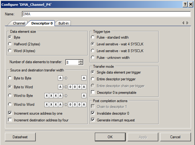
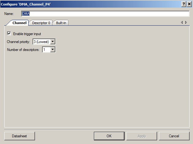
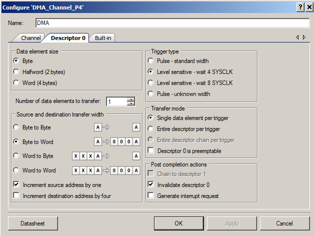
Next configure the DMA. The memory array that I have will be “uint8_t” aka “char”. So the input needs to be “bytes”. The UART FIFO hold Words… aka 4 bytes. So I need to configure the transfers to do “Byte to Word”. After the DMA transfer is done, I setup the DMA to create an interrupt (so that I can reset everything in the CPU) and to invalidate the descriptor.
In the firmware works by
- Turning on the UART
- Enabling the DMA
- Setting up the channel with the address of the buffer that I am going to write to (aka the TX FIFO) and asking for an interrupt
Then looping:
- When the User presses “s” or the switch, I set myFlag to be 1.
- If it is 1 and the channel is inactive, then initialize the “source” address, setup the number of transfer elements to be the number in my array, validate the descriptor, and turn on the channel.
When the channel turns on, the Tx fifo will be empty so it will assert the Tx Out, which will make the DMA keep triggering and copying 1 byte at a time into the FIFO. While this is happening, the UART will try to empty the fifo by sending the bytes. Finally when the DMA reaches the end of the RAM buffer, it will stop, and at some point the TX FIFO will finish emptying. The DMA will trigger the interrupt to toggle the BLUE LED. And the whole process can start again.
#include "project.h"
#include <stdio.h>

// A flag to trigger the DMA
volatile int myFlag=0;

static const char myArray[]="asdf1234asdfadsfasdfadsfqwerasdfqwerqwer9\n";

CY_ISR(sw_handler)
{
    myFlag = 1;
    SW_ClearInterrupt();
}

// This is called TWICE at the end of the DMA transaction
CY_ISR(myDMA)
{
    BLUE_Write(~BLUE_Read());
}
int main(void)
{
    CyIntEnable(CYDMA_INTR_NUMBER);
    CyGlobalIntEnable; /* Enable global interrupts. */

    char c;

    UART_Start();
    UART_UartPutString("Started\n");

    isr_1_StartEx(sw_handler);

    CyDmaEnable();

    DMA_Init();
    DMA_SetDstAddress(0, (void *)UART_TX_FIFO_WR_PTR);
    DMA_SetInterruptCallback(myDMA);

    while(1)
    {
        c = UART_UartGetChar();
        switch(c)
        {
            case 's':
                myFlag = 1;
            break;
        }

        // This turns on the DMA so that the string will go to the UART.
        if(myFlag && CyDmaGetActiveChannels() == 0)
        {
            DMA_SetSrcAddress(0, (void *)myArray);
            DMA_SetNumDataElements(0,strlen(myArray)-1);
            DMA_ValidateDescriptor(0);
            DMA_ChEnable();
            myFlag=0;
        }
    }
}
PSoC DMA Streamport
Now that I understand how to use the DMA, I can create the PSoC DMA Streamport by copying the project “1-BlionkingLED_UART_TRACE” project and calling it “1-BlinkingLED_UART_TRCE_DMA”. Next, add the DMA and modify the UART.
Configure the UART
Turn on the UART DMA and set the level to 7
Configure the DMA Block
Make byte transfers and byte –> word.
Finally modify the trcStreamingPort.c – AKA the PSoC DMA Streamport file. Specifically you need to fix up the PSoC_Transmit to send out the data when the TraceRecorder buffer is full.
- If the DMA is busy… then wait until the previous transaction is done.
- Then setup the DMA and let it rip.
int32_t PSoC_Transmit(void* data, uint32_t size, int32_t *numOfBytesSent )
{

    while( CyDmaGetActiveChannels()& DMA_CHANNEL_MASK);
    DMA_SetSrcAddress(0, (void *)data);
    DMA_SetNumDataElements(0,size);
    DMA_ValidateDescriptor(0);
    DMA_ChEnable();

    *numOfBytesSent=size;

    return 0; // Doesnt matter what you return... i dont think that it is checked
}
The only other thing that needs to happen is configure the DMA in main.c
    CyDmaEnable();
    DMA_Init();
    DMA_SetDstAddress(0, (void *)UART_TX_FIFO_WR_PTR);
Testing the PSoC DMA Streamport
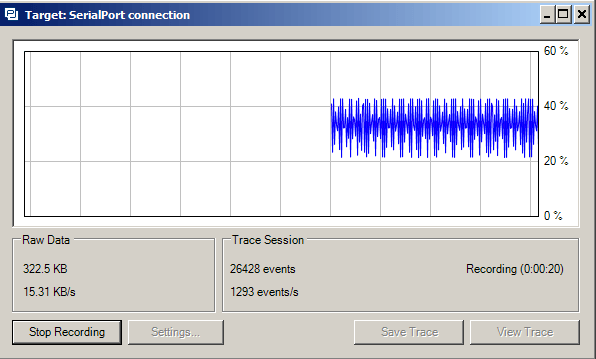
Now when I startup the Tracealyzer, here is what I get:
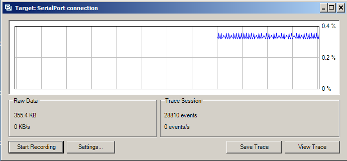
It looks like I solved my problem because that is way way better than:
As always you can find all of these projects on the IotExpert GitHub site or git@github.com:iotexpert/PSoC-Tracelyzer.git
Article
Description
Percepio Tracealyzer & PSoC
An Introduction to Percepio Tracealyzer on the Cypress PSoC
Percepio Tracealyzer RTT Streamport - PSoC4200M
Make the JLINK RTT Library work with Tracealyzer
Percepio Tracealyzer PSoC UART Streamport
Creating a UART Streamport
Percepio Tracealyzer - Analyzing the PSoC Tracealyzer Streamport
Figure out what is broken in the UART Streamport
Percepio Tracealyzer - Using PSoC DMA to Fix the UART Streamport
Implementing PSoC DMA to improve the CPU Utilization
Percepio Tracealyzer - Running on PSoC6
Porting the Percepio Tracealyzer to PSoC6
No comment yet, add your voice below!