Summary
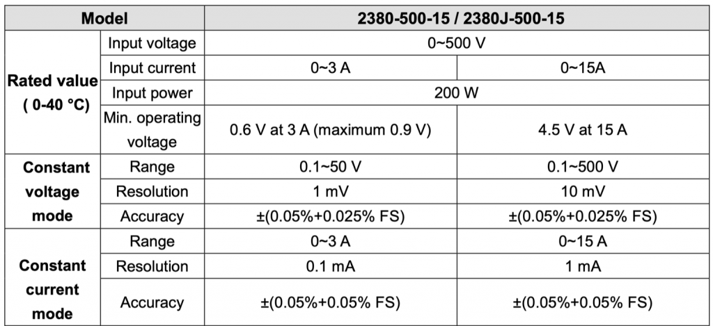
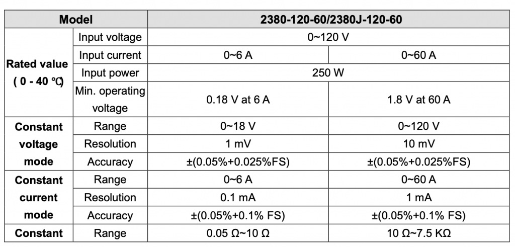
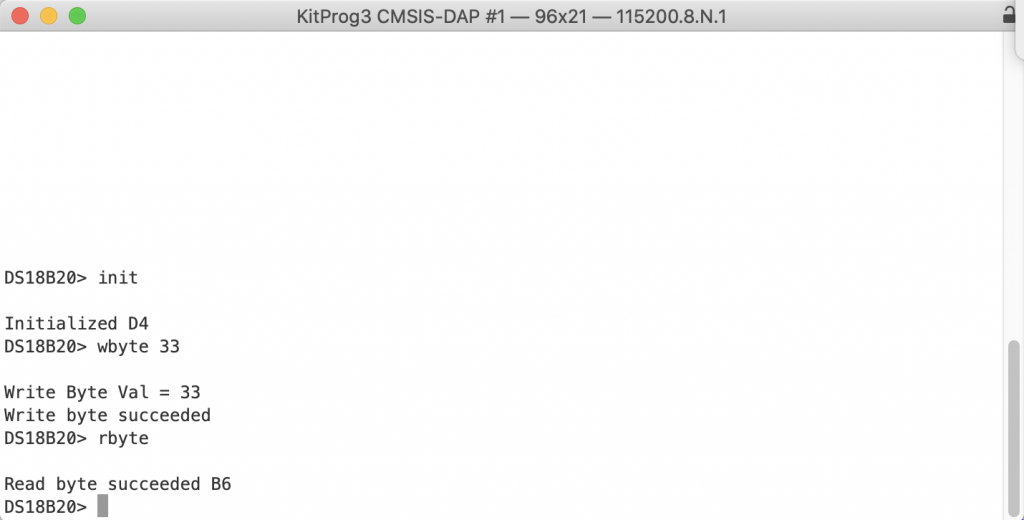
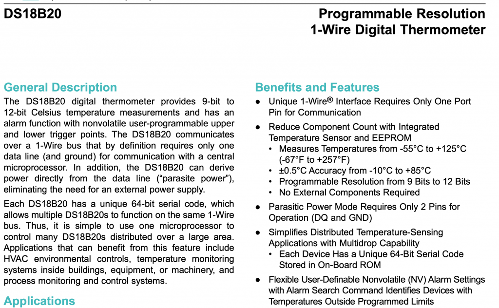
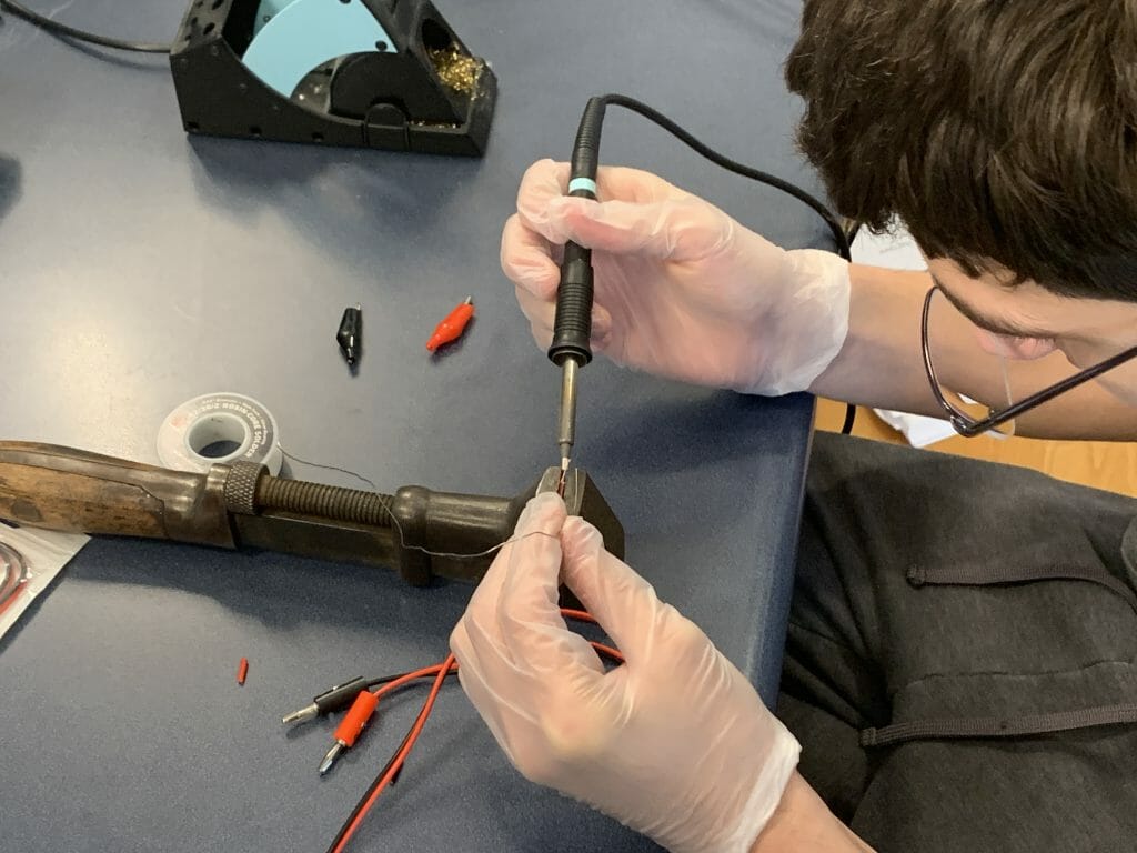
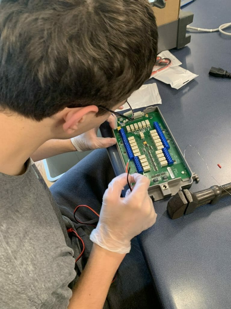
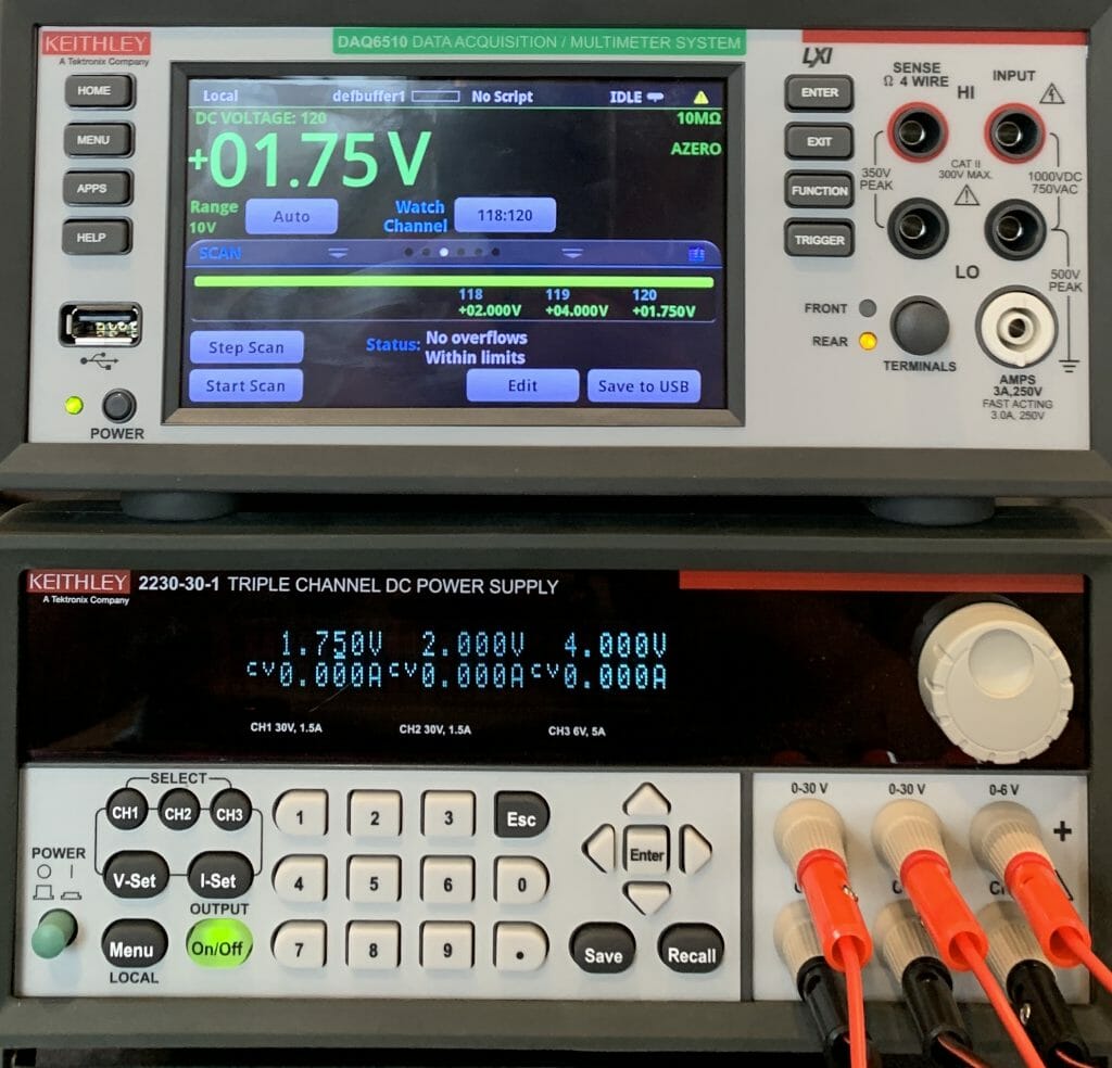
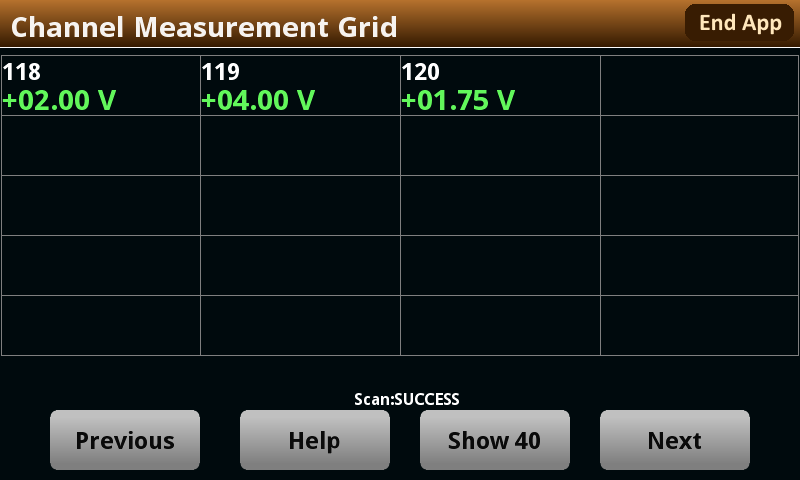
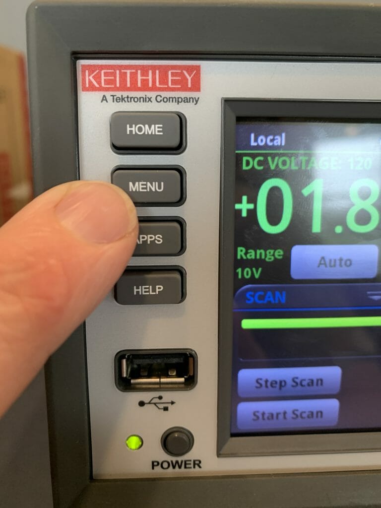
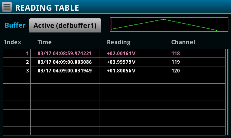
This article shows the completion of the PSoC 6 SDK One Wire Bus library. It shows the test apparatus for evaluating DS18B20 sensors.
Story
If you remember from the previous articles, I created the one wire bus library by looking at the function calls in the DS18B20 library and reverse engineering the function prototypes. And, as I said in the earlier article, it would have been way better to just look at the David Antliff “OWB” library. But that is not how it went down. I wonder how much time in the world is wasted by programmer re-implementing code that already exists?
After the first four articles, I had three functions which the DS18B20 library defined, but I had not yet implemented.
owb_ret_t owb_write_rom_code(OneWireBus *bus, OneWireBus_ROMCode romcode);

owb_ret_t owb_crc8_bytes(uint32_t val, uint8_t *buffer, uint32_t length);

void   owb_set_strong_pullup( OneWireBus *bus, bool val);
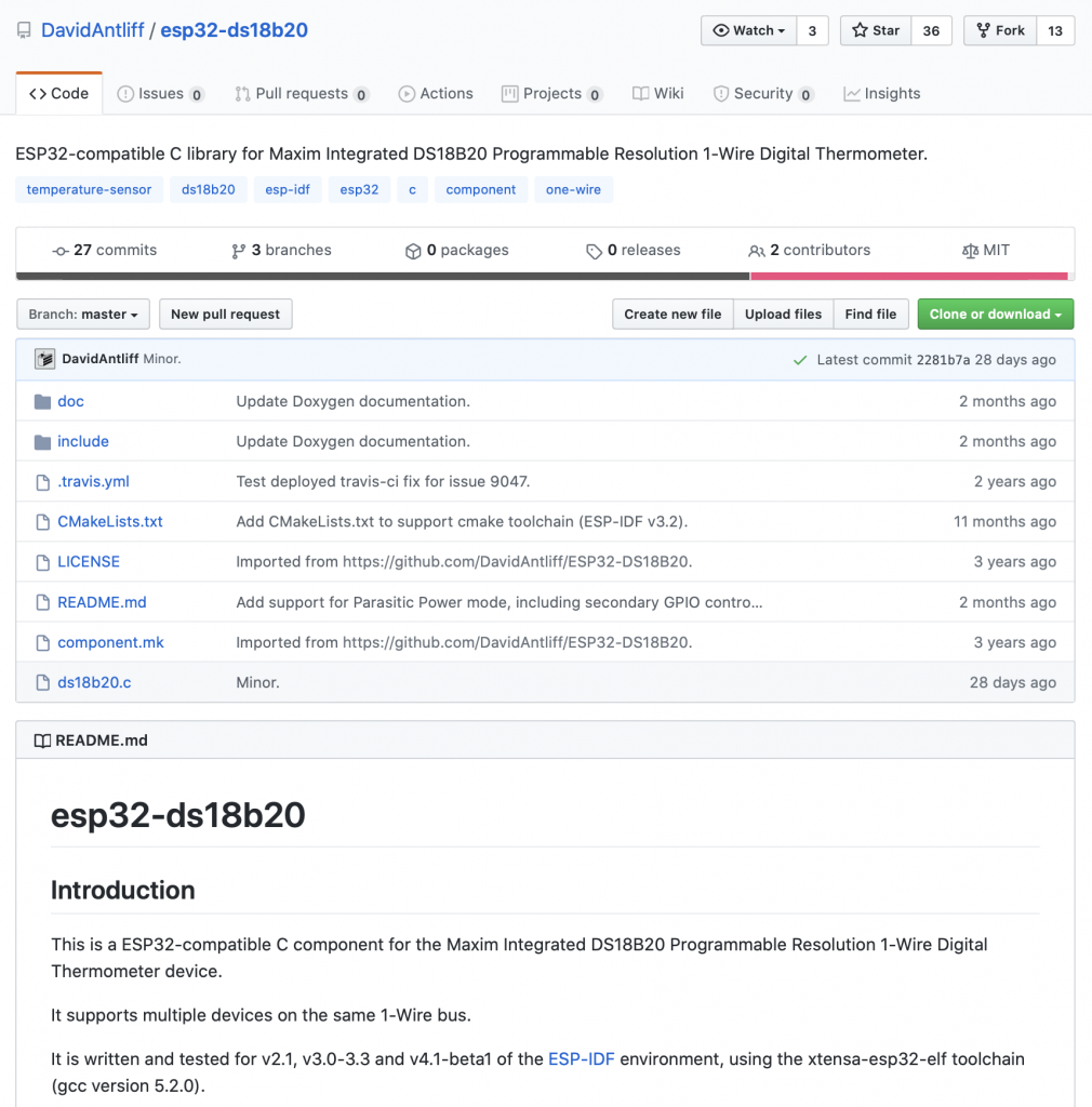
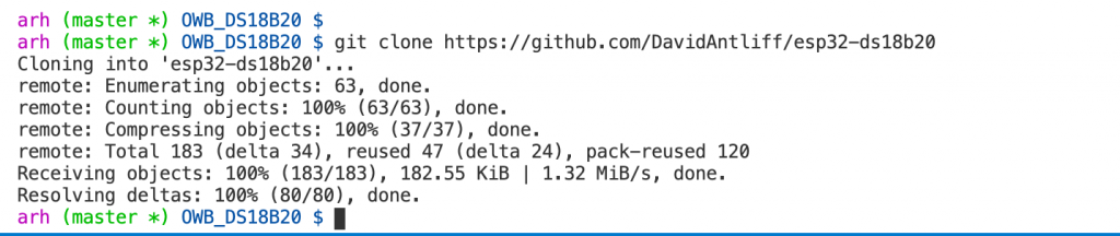
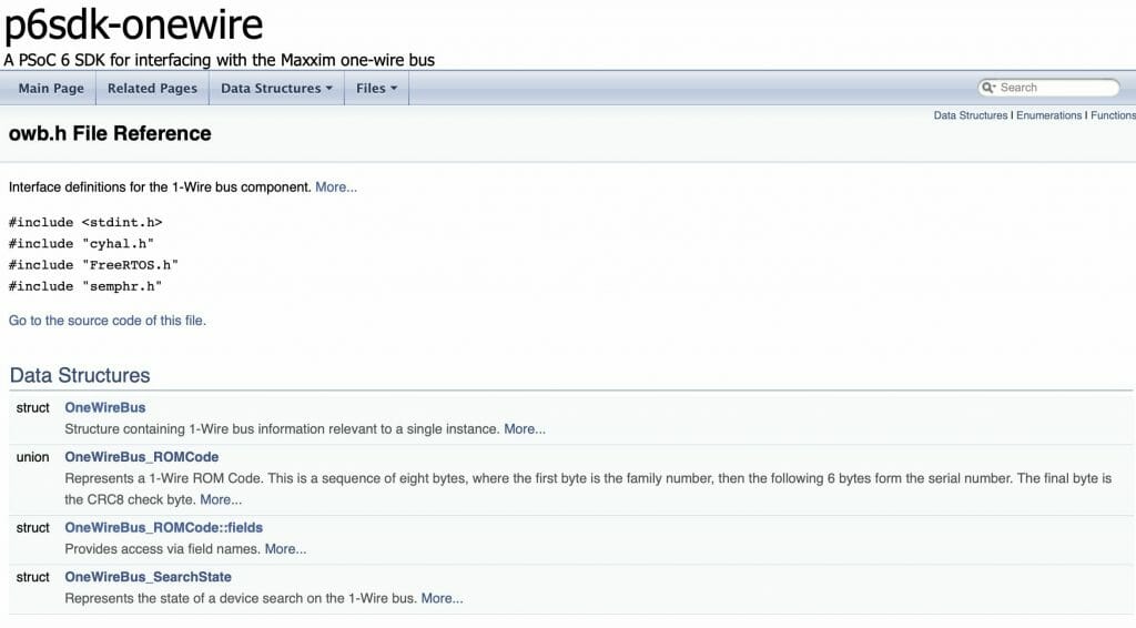
I had not implemented them because I was not totally sure how they worked. So, I decided to go back to GitHub and see what David had done originally. When I got to the GitHub site, https://github.com/DavidAntliff/esp32-owb/blob/master/include/owb.h, there were actually quite a few functions in his owb library that I had not implemented.
Here is the list:
owb_ret_t owb_use_crc(OneWireBus * bus, bool use_crc);
owb_ret_t owb_use_parasitic_power(OneWireBus * bus, bool use_parasitic_power);
owb_ret_t owb_use_strong_pullup_gpio(OneWireBus * bus, cyhal_gpio_t gpio);
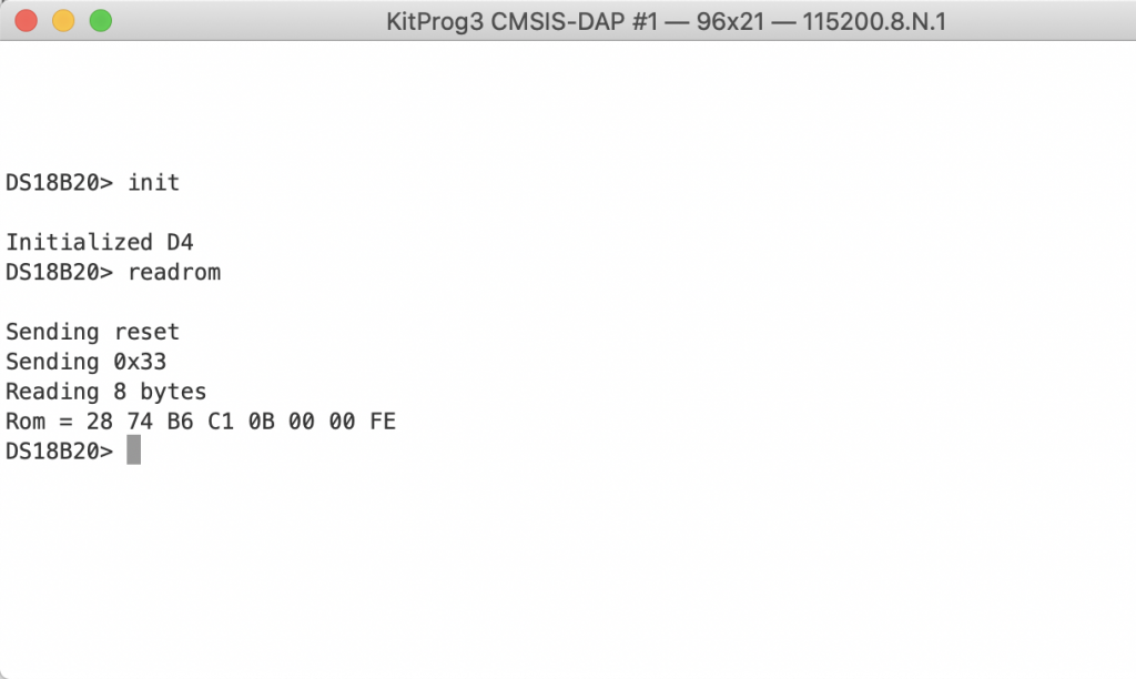
owb_ret_t owb_read_rom(OneWireBus * bus, OneWireBus_ROMCode * rom_code);
owb_ret_t owb_verify_rom(OneWireBus * bus, OneWireBus_ROMCode *rom_code, bool * is_present);
owb_ret_t owb_write_rom_code(OneWireBus * bus, OneWireBus_ROMCode *rom_code);
uint8_t owb_crc8_byte(uint8_t crc, uint8_t data);
uint8_t owb_crc8_bytes(uint8_t crc, const uint8_t * data, size_t len);
owb_ret_t owb_search_first(OneWireBus * bus, OneWireBus_SearchState * state, bool *found_device);
owb_ret_t owb_search_next(OneWireBus * bus, OneWireBus_SearchState * state, bool *found_device);
char * owb_string_from_rom_code(OneWireBus_ROMCode *rom_code, char * buffer, size_t len);
owb_ret_t owb_set_strong_pullup(OneWireBus * bus, bool enable);
In this article I will create and/or copy the missing functions. As I look through his implementation I also notice that we have some style differences that I will discuss. In general I will say that his implementation is very good and any place that I did something different was just a matter of programming taste.
I was originally planning on this article taking you linearly through how I did the changes, but in reality I jumped around while I was doing the changes, that approach won’t work. Here is the list of what I did:
- Add Doxygen Function Headers
- Move Logging Function to Library
- Change Commands to Enumerated Type
- Change Const Bus Pointer
- Pack the Structures
- Pass Structures as Pointers
- Driver Functions
- Test the Search
- Test the Parastitic Power
Doxygen Headers
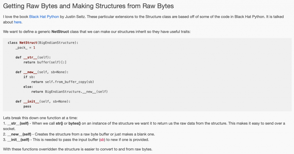
I like using documentation that has been generated with Doxygen. Specifically I like that the documentation is written “at the point of attack”. But I have never actually used or generated it using Doxygen. To make the documentation you need to put comments into your c-header files in the right format. Here is an example from owb.h
/**
* @brief Represents a set of the legal one wire bus commands
*/
typedef enum {
OWB_ROM_SEARCH =0xF0, ///< Perform Search ROM cycle to identify devices on the bus
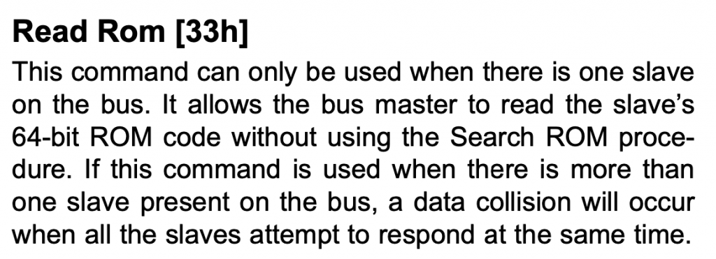
OWB_ROM_READ =0x33, ///< Read device ROM (single device on bus only)
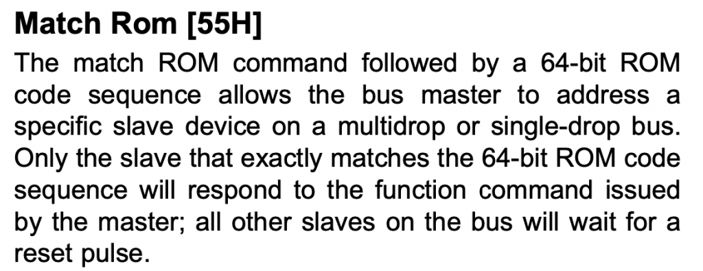
OWB_ROM_MATCH =0x55, ///< Address a specific device on the bus by ROM
OWB_ROM_SKIP =0xCC, ///< Address all devices on the bus simultaneously
OWB_ROM_SEARCH_ALARM =0xEC, ///< Address all devices on the bus with a set alarm flag
} owb_commands_t;
In this case, David had done most of the work already and all I needed to do was copy/modify his headers in the few places where we had differences in the public interface to the library. After that, I ran doxygen. When I first did this I got an absolute boatload of warnings about places where I had not documented with comments. If Hassane is reading he will say … “Really Alan didn’t write comments, imagine that”
arh (master *) p6sdk-onewire $ doxygen
Doxygen version used: 1.8.18
Searching for include files...
Searching for example files...
Searching for images...
Searching for dot files...
Searching for msc files...
Searching for dia files...
Searching for files to exclude
Searching INPUT for files to process...
Searching for files in directory /Users/arh/proj/owb-ds18b20/DS18B20Test/p6sdk-onewire
Reading and parsing tag files
Parsing files
Reading /Users/arh/proj/owb-ds18b20/DS18B20Test/p6sdk-onewire/README.md...
Preprocessing /Users/arh/proj/owb-ds18b20/DS18B20Test/p6sdk-onewire/owb.c...
Parsing file /Users/arh/proj/owb-ds18b20/DS18B20Test/p6sdk-onewire/owb.c...
Preprocessing /Users/arh/proj/owb-ds18b20/DS18B20Test/p6sdk-onewire/owb.h...
Parsing file /Users/arh/proj/owb-ds18b20/DS18B20Test/p6sdk-onewire/owb.h...
Building group list...
Building directory list...
Building namespace list...
Building file list...
Building class list...
Computing nesting relations for classes...
Associating documentation with classes...
Building example list...
Searching for enumerations...
Searching for documented typedefs...
Searching for members imported via using declarations...
Searching for included using directives...
Searching for documented variables...
Building interface member list...
Building member list...
Searching for friends...
Searching for documented defines...
Computing class inheritance relations...
Computing class usage relations...
Flushing cached template relations that have become invalid...
Computing class relations...
Add enum values to enums...
Searching for member function documentation...
Creating members for template instances...
Building page list...
Search for main page...
Computing page relations...
Determining the scope of groups...
Sorting lists...
Determining which enums are documented
Computing member relations...
Building full member lists recursively...
Adding members to member groups.
Computing member references...
Inheriting documentation...
Generating disk names...
Adding source references...
Adding xrefitems...
Sorting member lists...
Setting anonymous enum type...
Computing dependencies between directories...
Generating citations page...
Counting members...
Counting data structures...
Resolving user defined references...
Finding anchors and sections in the documentation...
Transferring function references...
Combining using relations...
Adding members to index pages...
Correcting members for VHDL...
Generating style sheet...
Generating search indices...
Generating example documentation...
Generating file sources...
Generating code for file owb.h...
Generating file documentation...
Generating docs for file owb.h...
Generating page documentation...
Generating docs for page md_README...
Generating group documentation...
Generating class documentation...
Generating docs for compound OneWireBus...
Generating docs for compound OneWireBus_ROMCode...
Generating docs for nested compound OneWireBus_ROMCode::fields...
Generating docs for compound OneWireBus_SearchState...
Generating namespace index...
Generating graph info page...
Generating directory documentation...
Generating index page...
Generating page index...
Generating module index...
Generating namespace index...
Generating namespace member index...
Generating annotated compound index...
Generating alphabetical compound index...
Generating hierarchical class index...
Generating member index...
Generating file index...
Generating file member index...
Generating example index...
finalizing index lists...
writing tag file...
Running plantuml with JAVA...
lookup cache used 45/65536 hits=385 misses=48
finished...
arh (master *) p6sdk-onewire $
Now I have some documentation
I will say that I wish I had a few days to really learn Doxygen as there are many many many options which I have no idea what they do. Oh well.
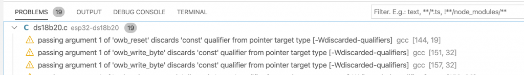
Fix the Logging Function
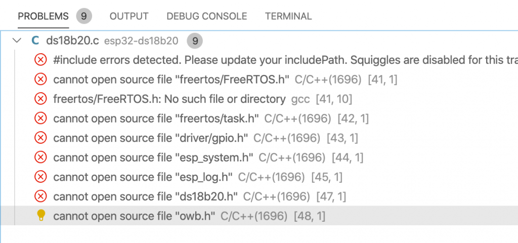
David built the library on top of the ESP32 libraries. This included calls to the ESP32 logging library “log.h/.c“. All through his library he calls “ESP_LOG” like this.
ESP_LOGE(TAG, "bus is NULL");
When I first looked at this I decided to just do this to make the error messages go away. This is just a trick that will use the c-preprocessor to replace the function call to “ESP32_LOGE” with NOTHING
#define ESP_LOGE(...)
After I sorted everything else out I went back to decide what to do. My choices were
- Clone the Espressif library and “fix it”
- Implement the functions that David used in the OWB library
- Find another library
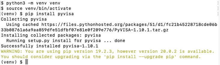
I decided to use option 3 – a logging library that I found on GitHub called “log.c” (which is a very unfortunate name when you clone it). It is really simple and works well. Since the Tour de France is going as I write this article I will say “chappeau rxi”. This library is written in C99 (just normal C) and has functions which can easily replace the ESP_LOG functions. I add it to my project with “git clone git@github.com:rxi/log.c.git”
log_trace(const char *fmt, ...);
log_debug(const char *fmt, ...);
log_info(const char *fmt, ...);
log_warn(const char *fmt, ...);
log_error(const char *fmt, ...);
log_fatal(const char *fmt, ...);
This means that I just replace “ESP_LOGE” with “log_error”. In reality rxi did something very nice by using a feature of the compiler to insert the file/line numbers.
#define log_trace(...) log_log(LOG_TRACE, __FILE__, __LINE__, __VA_ARGS__)
This only left me with the function
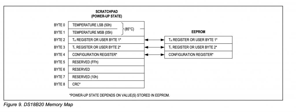
ESP_LOG_BUFFER_HEX_LEVEL(TAG, scratchpad, count, ESP_LOG_DEBUG);
Which I decided to do something cheap to solve. The original code was:
//ESP_LOG_BUFFER_HEX_LEVEL(TAG, &scratchpad->trigger_high, 3, ESP_LOG_DEBUG);
And I replaced the two uses with:
log_debug( "scratchpad write 3 bytes:%02X%02X%02X",scratchpad[0],scratchpad[1],scratchpad[2]);
and
                //ESP_LOG_BUFFER_HEX_LEVEL(TAG, scratchpad, count, ESP_LOG_DEBUG);
                log_debug( "%02X%02X%02X%02X%02X%02X%02X%02X%02X",
                    scratchpad[0],scratchpad[1],scratchpad[2],
                    scratchpad[3],scratchpad[4],scratchpad[5],
                    scratchpad[6],scratchpad[7],scratchpad[8]);
I know it isn’t beautiful what I did, but it works.
Enumerated Command Type
When I examined the original source code, the one-wire commands were defined using #defines.
// ROM commands
#define OWB_ROM_SEARCH        0xF0  ///< Perform Search ROM cycle to identify devices on the bus
#define OWB_ROM_READ          0x33  ///< Read device ROM (single device on bus only)
#define OWB_ROM_MATCH         0x55  ///< Address a specific device on the bus by ROM
#define OWB_ROM_SKIP          0xCC  ///< Address all devices on the bus simultaneously
#define OWB_ROM_SEARCH_ALARM  0xEC  ///< Address all devices on the bus with a set alarm flag
When I did the implementation originally I chose to make the #defines into an enumerated list. I suppose that it doesn’t really matter. But, by enumerating the values it lets the compiler help you in situations like a switch or a function call.
typedef enum {
    OWB_ROM_SEARCH        =0xF0,  ///< Perform Search ROM cycle to identify devices on the bus
    OWB_ROM_READ          =0x33,  ///< Read device ROM (single device on bus only)
    OWB_ROM_MATCH         =0x55,  ///< Address a specific device on the bus by ROM
    OWB_ROM_SKIP          =0xCC,  ///< Address all devices on the bus simultaneously
    OWB_ROM_SEARCH_ALARM  =0xEC,  ///< Address all devices on the bus with a set alarm flag
} owb_commands_t;
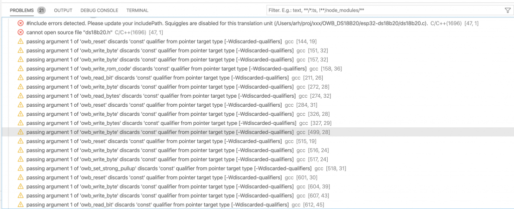
Const Bus pointer
Through out the original one wire bus library, the bus pointer is defined as const. Like this:
owb_status owb_read_rom(const OneWireBus * bus, OneWireBus_ROMCode * rom_code)
But, I wanted to use the OneWireBus structure to also store some context. By context I mean variables (which can change) but hold state for the bus. This included the semaphore that I used to fix the delay functions.
/**
 * @brief Structure containing 1-Wire bus information relevant to a single instance.
 */
typedef struct
{
    cyhal_gpio_t  pin;                   ///<Pin that the bus is attached to
    cyhal_gpio_t strong_pullup_gpio;     ///<Pin that the pullup gpio is attached to
    bool use_parasitic_power;            ///<Driver is using parastic power mode
    bool use_crc;                        ///<Enable the use of crc checks on the ROM
    // Internal use only
    bool is_init;                        ///<Private
    bool detect;                         ///<Private
    SemaphoreHandle_t signalSemaphore;   ///<Private
    cyhal_timer_t bitTimer;              ///<Private
    SemaphoreHandle_t owb_num_active;    ///<Private
    uint8_t scratchBitValue;             ///<Private
} OneWireBus;
ROM Code Structure Packed
In the original library the ROMCode is a union that allows access to individual bytes, or the actual data.
typedef union
{
    /// Provides access via field names
    struct fields
    {
        uint8_t family[1];         ///< family identifier (1 byte, LSB - read/write first)
        uint8_t serial_number[6];  ///< serial number (6 bytes)
        uint8_t crc[1];            ///< CRC check byte (1 byte, MSB - read/write last)
    } __PACKED fields;             ///< Provides access via field names

    uint8_t bytes[8];              ///< Provides raw byte access

} OneWireBus_ROMCode;
The problem is there is no guarantee that the compiler will pack the family, serial number and crc. You should tell it to with the __PACKED macro. I would say that I think that David got luck that there was not a bug.
/**
 * @brief Represents a 1-Wire ROM Code. This is a sequence of eight bytes, where
 *        the first byte is the family number, then the following 6 bytes form the
 *        serial number. The final byte is the CRC8 check byte.
 */
typedef union
{
    /// Provides access via field names
    struct fields
    {
        uint8_t family[1];         ///< family identifier (1 byte, LSB - read/write first)
        uint8_t serial_number[6];  ///< serial number (6 bytes)
        uint8_t crc[1];            ///< CRC check byte (1 byte, MSB - read/write last)
    } __PACKED fields;             ///< Provides access via field names

    uint8_t bytes[8];              ///< Provides raw byte access

} OneWireBus_ROMCode;
C-Programming: Passing Structures as Function Arguments
In the original library David passed the rom_code structure as an argument on the stack. But, because I started programming in the days before it was legal to pass a structure as a function argument when I did the implementation I passed a pointer.
owb_status owb_verify_rom(const OneWireBus * bus, OneWireBus_ROMCode rom_code, bool * is_present);
I wrote
owb_ret_t owb_verify_rom(OneWireBus * bus, OneWireBus_ROMCode *rom_code, bool * is_present);
Which meant that he could write
        OneWireBus_SearchState state = {
            .rom_code = rom_code,
            .last_discrepancy = 64,
            .last_device_flag = false,
        };
but I had to write
        OneWireBus_SearchState state = {
            //.rom_code = rom_code,
            .last_discrepancy = 64,
            .last_device_flag = false,
        };

        memcpy(&state.rom_code,rom_code,sizeof(OneWireBus_ROMCode));
In this case it doesn’t really matter as the structure is small.
Driver Functions
If you look at the original implementation the author has a “driver”
typedef struct
{
    const struct _OneWireBus_Timing * timing;   ///< Pointer to timing information
    bool use_crc;                               ///< True if CRC checks are to be used when retrieving information from a device on the bus
    bool use_parasitic_power;                   ///< True if parasitic-powered devices are expected on the bus
    gpio_num_t strong_pullup_gpio;              ///< Set if an external strong pull-up circuit is required
    const struct owb_driver * driver;           ///< Pointer to hardware driver instance
} OneWireBus;
Which is a structure with function pointers to talk to bus.
/** NOTE: Driver assumes that (*init) was called prior to any other methods */
struct owb_driver
{
    /** Driver identification **/
    const char* name;

    /** Pointer to driver uninitialization function **/
    owb_status (*uninitialize)(const OneWireBus * bus);

    /** Pointer to driver reset functio **/
    owb_status (*reset)(const OneWireBus * bus, bool *is_present);

    /** NOTE: The data is shifted out of the low bits, eg. it is written in the order of lsb to msb */
    owb_status (*write_bits)(const OneWireBus *bus, uint8_t out, int number_of_bits_to_write);

    /** NOTE: Data is read into the high bits, eg. each bit read is shifted down before the next bit is read */
    owb_status (*read_bits)(const OneWireBus *bus, uint8_t *in, int number_of_bits_to_read);
};
Which meant that he did this:
bus->driver->read_bits(bus, &id_bit, 1);
bus->driver->read_bits(bus, &cmp_id_bit, 1);
In my implementation I wrote functions for those things.
owb_read_bit(bus,&id_bit);
owb_read_bit(bus,&cmp_id_bit);
I don’t really think that it helped abstract the hardware because he also did this.
gpio_set_level(bus->strong_pullup_gpio, enable ? 1 : 0);
Perhaps a driver with function pointers would have made the original port easier if I had started there? But if so, it would have required more adherence to the original architecture.
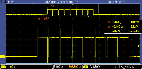
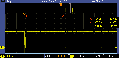
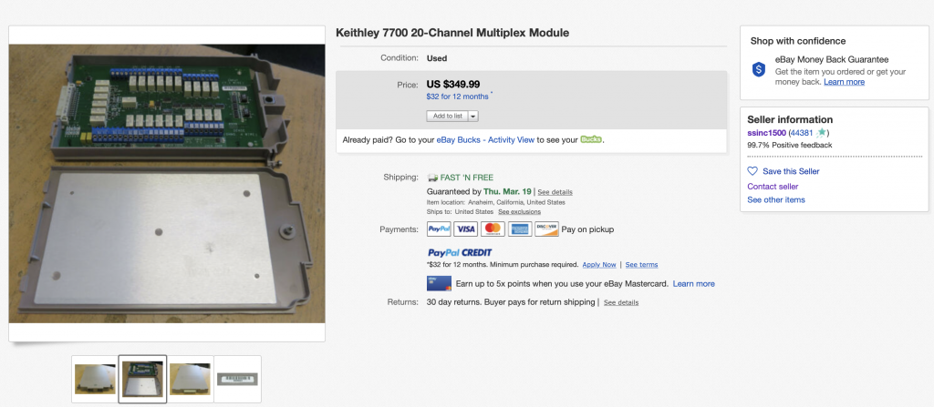
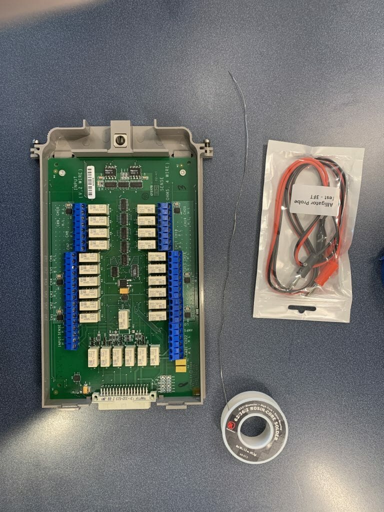
Test Search
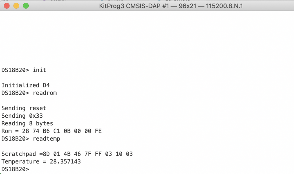
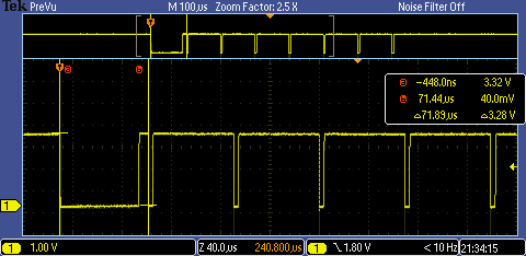
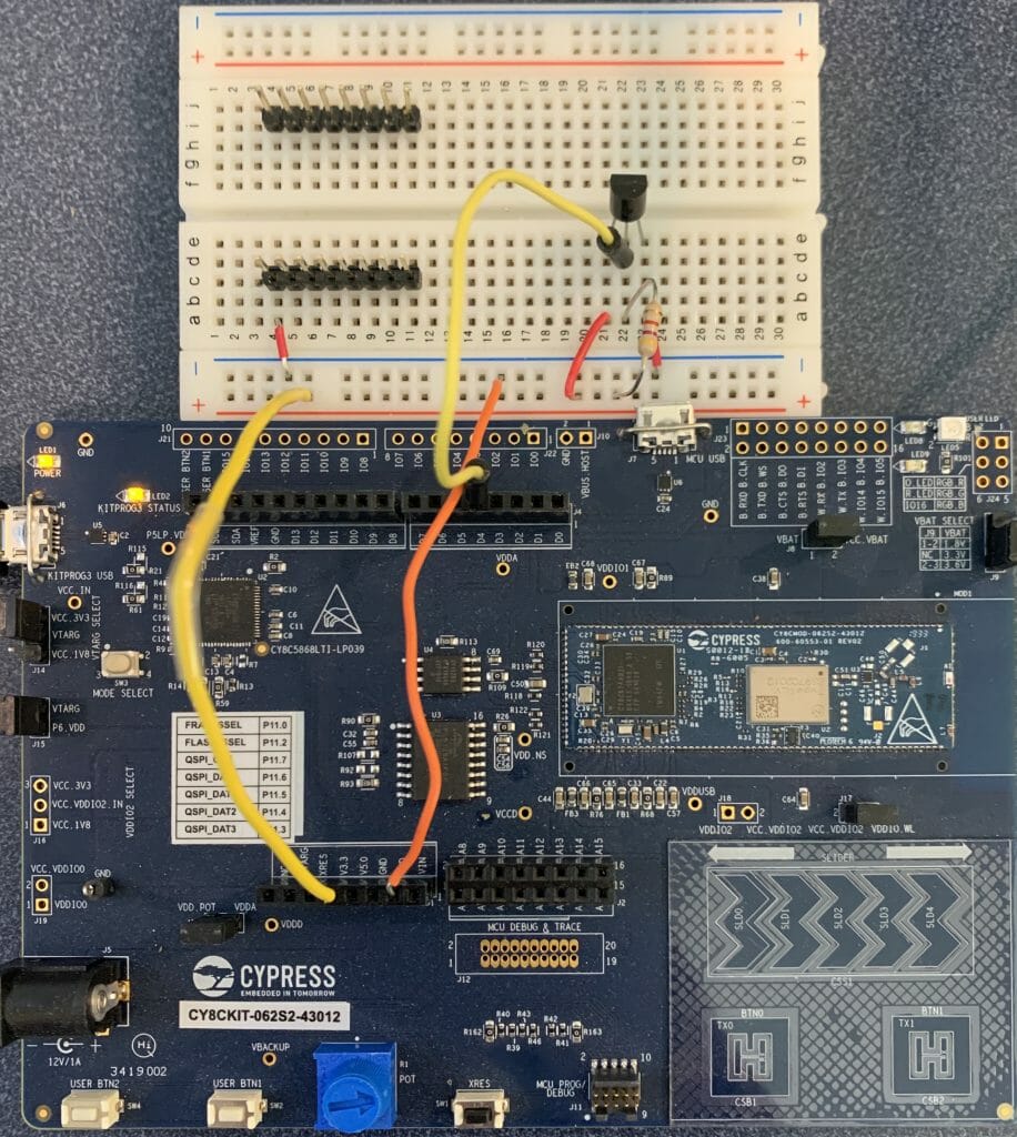
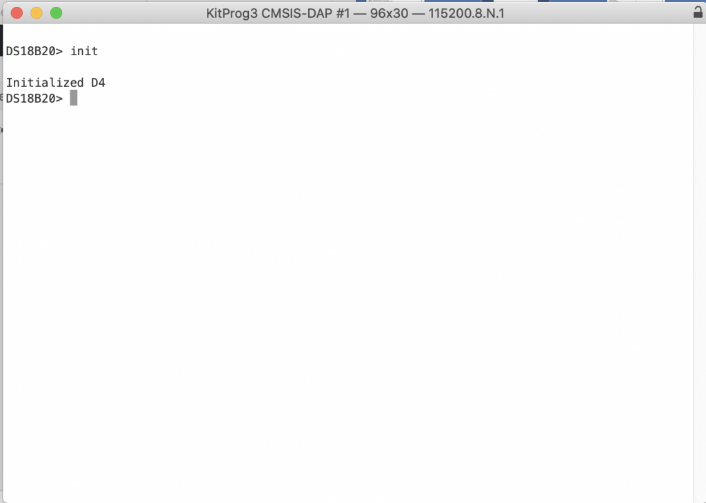
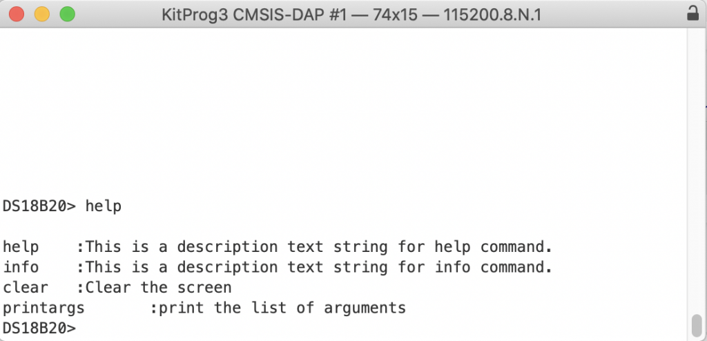
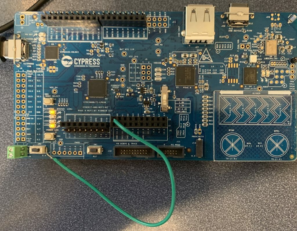
A nice thing that came with his library was an implementation of the search feature which allows multiple devices to be attached to the bus. To test this I added two sensors.
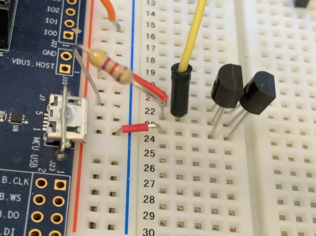
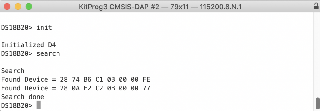
Then made a command in my console to run the test.
static int usrcmd_search(int argc, char **argv)
{
    printf("Search\n");
    OneWireBus_SearchState state;
    bool found_device;

    owb_search_first(&bus, &state, &found_device);

    do {
        if(found_device)
        {
            printf("Found Device = ");
            for(int i=0;i<8;i++)
            {
                printf("%02X ",state.rom_code.bytes[i]);
            }
            printf("\n");
        }

        owb_search_next(&bus, &state, &found_device);

    } while(found_device);

    printf("Search done\n");
    return 0;
}
Which worked perfectly.
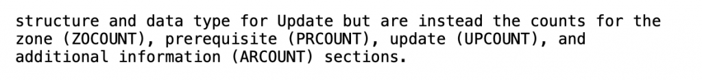
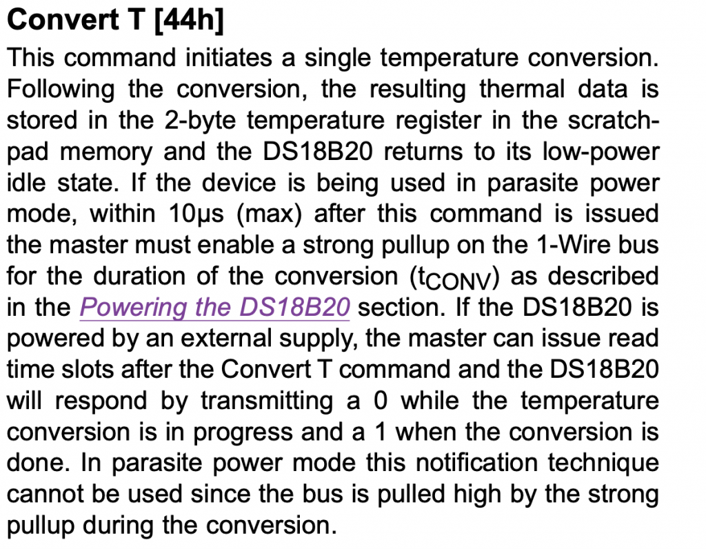
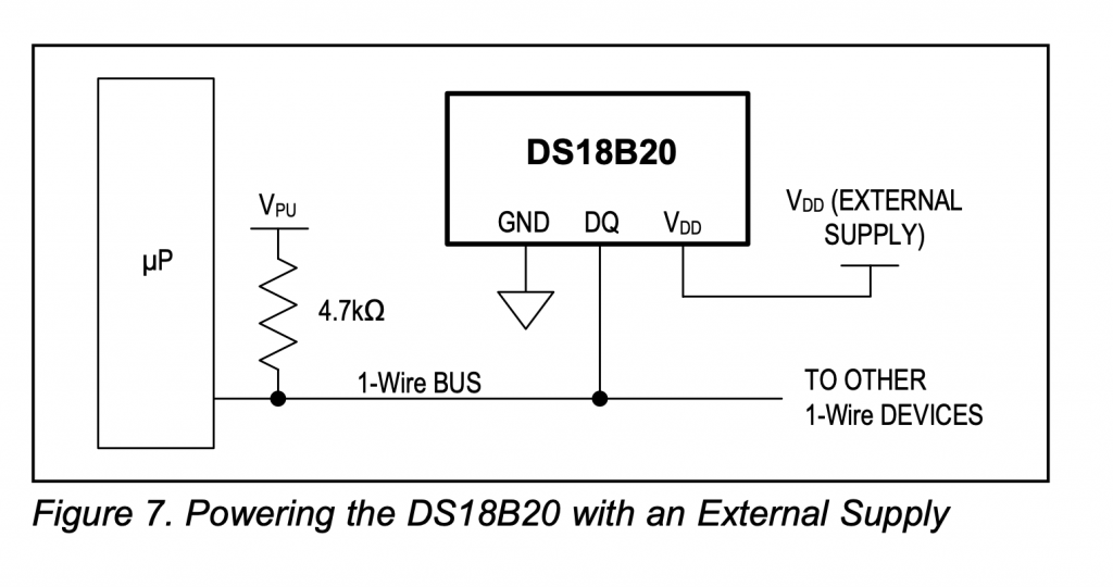
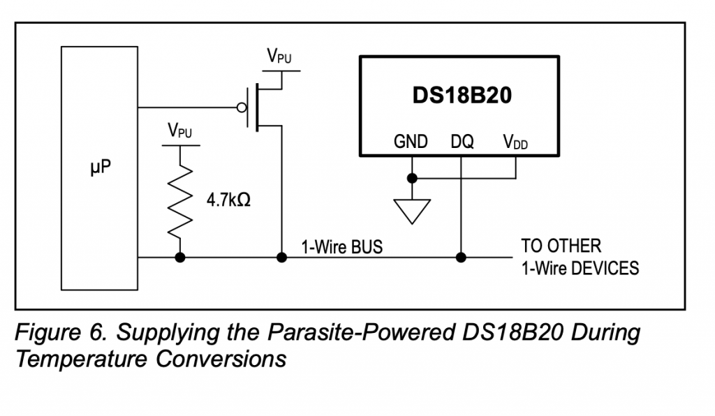
Parasitic Power
I would like to test the functionality of the parasitic power. Here is a schematic from the data sheet of how it work. But I don’t have that transistor so that will be left for another day.
What is Next?
There are several things that I should do.
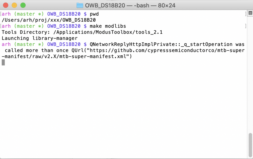
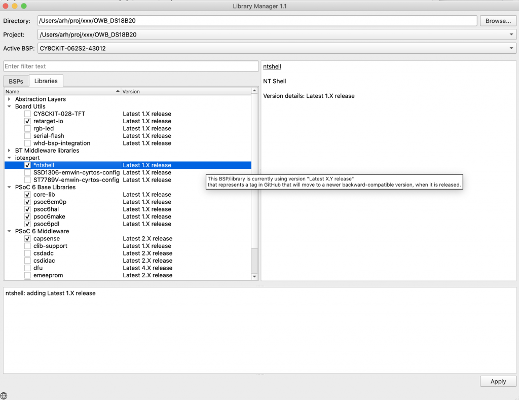
- Fix up the libraries to use the manifest files so they are available all of the time
- Fix up the libraries to use the dependency scheme
- Test the parasitic power
- Test the actual DS18B20 library (the original point of this whole thing)
I have found myself in the middle of a bunch of other problems, so these things will need to happen another day.