Summary
In this article I will explain how to implement (badly) the one wire bus read & write functions using the PSoC 6 SDK. This is one of many articles that are part of a series discussing the implementation:
| Article |
|---|
| PSoC 6 SDK OneWire Bus (Part 1) : Build Basic Project |
| PSoC 6 SDK OneWire Bus (Part 2) : Implement Read & Write |
| PSoC 6 SDK OneWire Bus (Part 3) : Remove Busy Wait & Debug |
| PSoC 6 SDK OneWire Bus (Part 4): But, Can it Read the Temperature? |
| PSoC 6 SDK OneWire Bus (Part 5): Round out the OWB Driver |
Story
In the previous article, I built a test framework inside of a PSoC 6 FreeRTOS project. This includes a command line shell which will enable me to execute functions based on typed commands. This means I can use the CLI shell to debug my interface. To get going testing, I bought a DS18B20 temperature sensor from Mouser.
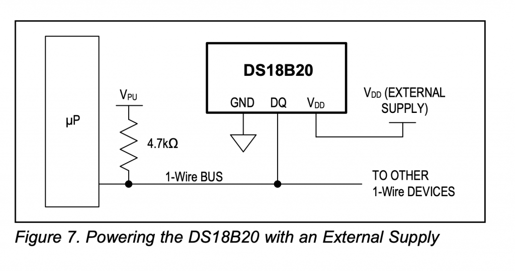
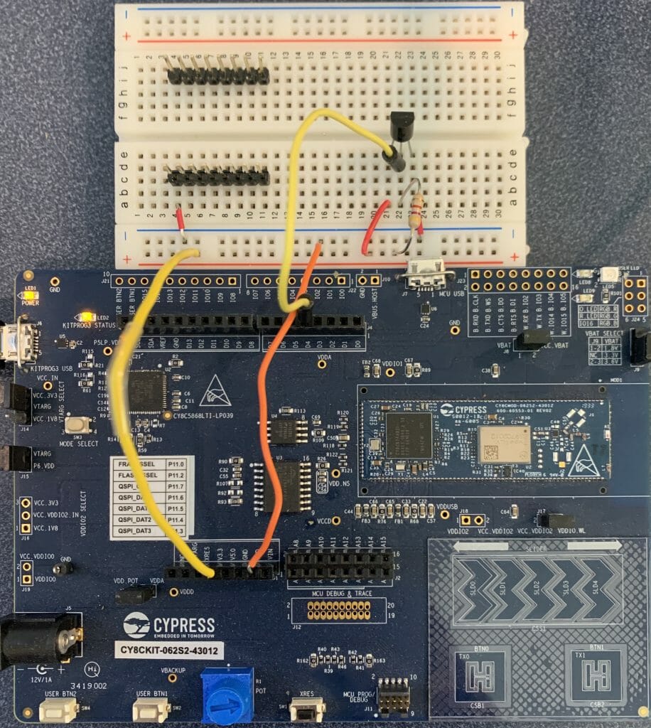
Then wired it like this:
Here is a picture of the test jig. It looks like I used 4200 ohms instead of 4400 ohms, oh well it seems to work.
Init
Init seems like a good place to start. To have a one wire bus you need to have a GPIO to read/drive. So, that will be the only argument to the initialization function. In the implementation I will use a common semaphore to handle blocking functions (line 13). On lines 15-17 I initialize a timer to handle the requirements of reset, read and writes (more on this later). At the end on line 20 I initialize the GPIO.
#include "owb.h"
#include <stdint.h>
#include "cyhal.h"
#include "cybsp.h"
#include "task.h"
#include <stdbool.h>
#include <stdio.h>

owb_ret_t owb_init(OneWireBus *bus)
{
    cy_rslt_t rslt;

    bus->signalSemaphore = xSemaphoreCreateBinary();

    rslt = cyhal_timer_init(&bus->bitTimer,NC,0);
    CY_ASSERT(rslt == CY_RSLT_SUCCESS);
    rslt = cyhal_timer_set_frequency(&bus->bitTimer,1000000);

    CY_ASSERT(rslt == CY_RSLT_SUCCESS);
    rslt = cyhal_gpio_init(bus->pin,CYHAL_GPIO_DIR_BIDIRECTIONAL,CYHAL_GPIO_DRIVE_OPENDRAINDRIVESLOW,true);
    CY_ASSERT(rslt == CY_RSLT_SUCCESS);
    return OWB_STATUS_OK;
}
In the usrcmd.c I need to add includes for the new stuff.
#include "cybsp.h"
#include "owb.h"
The next step is to add the “init” command to usrcmd.c This is accomplished by adding a function header for usrcmd_init and adding it to the table of legal commands.
static int usrcmd_init(int argc, char **argv);

typedef struct {
    char *cmd;
    char *desc;
    USRCMDFUNC func;
} cmd_table_t;

static const cmd_table_t cmdlist[] = {
    { "help", "This is a description text string for help command.", usrcmd_help },
    { "info", "This is a description text string for info command.", usrcmd_info },
    { "clear", "Clear the screen", usrcmd_clear },
    { "printargs","print the list of arguments", usrcmd_printargs},
    { "init","Initialize the 1-wire bus", usrcmd_init},

};
Then you need to add the usrcmd_init function to call the owb init.
static OneWireBus bus;
static int usrcmd_init(int argc, char **argv)
{
bus.pin = CYBSP_D4;
owb_init(&bus);
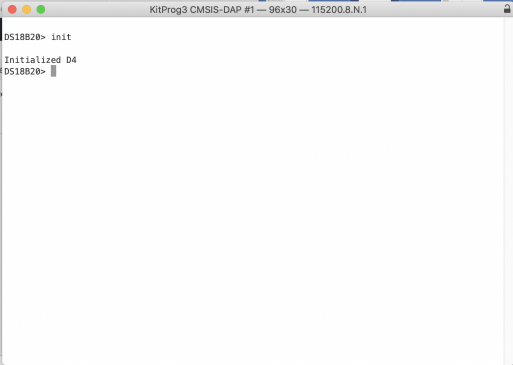
printf("Initialized D4\n");
return 0;
}
Now test it. All good.
Reset
In order to reset the bus you follow this process
- Pull down the bus for trstl=480uS
- Let the bus go back to 1 (remember that it is restive pull-up)
- Wait another trsth=480uS
- If there is a slave device on the bus it will pull down the bus at some point to indicate a “presence detect”
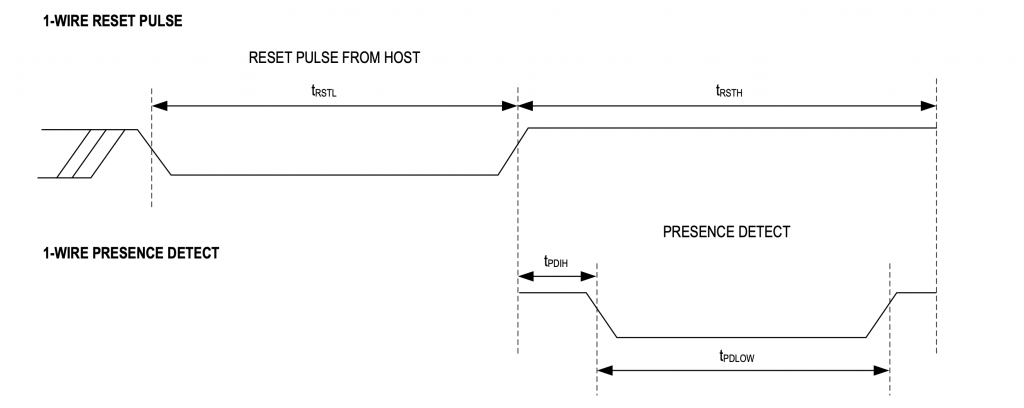
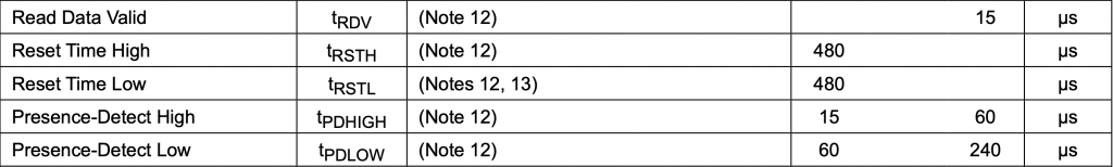
From the data sheet you can see that the low& high times = 480uS. At some point during the high period the slave will pull the bus down for 15->60uS
In order to implement the reset I will modify the owb.c file. To meet the timing requirements I will use a cyhal_timer. The cyhal_timer is implemented in the Cypress PDL at a Cy_TCPWM_Timer which is then implemented in the hardware as a timer counter. In this configuration the timer has:
- A Counter (an up or down counter)
- A Compare (a register which can be compared with the counter to trigger events)
- A Period (a register which is compared to the counter to reset the counter back to 0). This event is also called the “terminal count”
For this implementation I will setup a timer with
- Input clock 1Mz (aka 1uS per count)
- An up counter
- Starts at 0
- Compare value = 480 (means trigger an interrupt at 480uS)
- Period = 960 (means trigger an interrupt at 480uS)
- One shot (stop counting when you get to period (aka Terminal Count))
The code will
- Configure the timer (line 41-52)
- Pull a 0 onto the bus (line 54)
- Start the timer (line 56)
- At the compare value 480uS reset the bus to 1 using the event handler (line 20) and setup the GPIO trigger a fall event interrupt (line 21-22)
- At the period release the semaphore (27-30)
- After the compare value if the GPIO pulls down, use the GPIO interrupt to record the presence of a device (line 10)
/////////////////////////////////////////////////////////////////////////////////////////////////////////////
// Reset
/////////////////////////////////////////////////////////////////////////////////////////////////////////////
static void reset_gpio_event_callback(void *callback_arg, cyhal_gpio_event_t event)
{
    OneWireBus *bus = (OneWireBus *)callback_arg;

    if(event & CYHAL_GPIO_IRQ_FALL)
    {
        bus->detect = true;
    }
}

static void reset_timer_event_callback(void *callback_arg, cyhal_timer_event_t event)
{
    OneWireBus *bus = (OneWireBus *)callback_arg;

    if(event & CYHAL_TIMER_IRQ_CAPTURE_COMPARE)
    {
        cyhal_gpio_write(bus->pin,1);
        cyhal_gpio_register_callback(bus->pin, reset_gpio_event_callback,(void *)bus);
        cyhal_gpio_enable_event(bus->pin,CYHAL_GPIO_IRQ_FALL,5,true);
    }
    if(event & CYHAL_TIMER_IRQ_TERMINAL_COUNT)
    {

        BaseType_t xHigherPriorityTaskWoken;
        xHigherPriorityTaskWoken = pdFALSE;
        xSemaphoreGiveFromISR(bus->signalSemaphore,&xHigherPriorityTaskWoken);
        portYIELD_FROM_ISR( xHigherPriorityTaskWoken );
    }

}

owb_ret_t owb_reset(OneWireBus *bus, bool *result)
{
    owb_ret_t rval = OWB_STATUS_OK;

    bus->detect = false;

    cyhal_timer_cfg_t cfgBit = {
        .is_continuous = false,
        .direction = CYHAL_TIMER_DIR_UP,
        .is_compare = true,
        .compare_value = 480,
        .period = 960,
        .value = 0
    };
    cyhal_timer_configure(&bus->bitTimer,&cfgBit);
    cyhal_timer_reset(&bus->bitTimer);
    cyhal_timer_register_callback(&bus->bitTimer,reset_timer_event_callback,bus);
    cyhal_timer_enable_event(&bus->bitTimer,CYHAL_TIMER_IRQ_ALL,5,true);

    cyhal_gpio_write(bus->pin,0);

    cyhal_timer_start(&bus->bitTimer);

    xSemaphoreTake(bus->signalSemaphore,2); // worst case is really 960uS
    cyhal_gpio_enable_event(bus->pin,CYHAL_GPIO_IRQ_FALL,5,true);
    return rval;
}
Once I have the owb_init code I add the init command to usrcmd.c.
static int usrcmd_reset(int argc, char **argv)
{
    bool result;
    owb_reset(&bus,&result);
    if(bus.detect)
    {
        printf("Reset Succeeded\n");

    }
    else

        printf("Reset Failed\n");

    return 0;
}
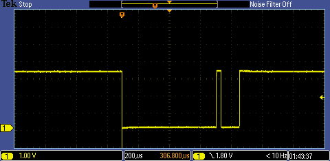
When I run it, I get this nice picture from the oscilliscope.
Write
In the ds18b20.c file I see that the author has three functions of interest. In the implementation owb_write_bytes will call owb_write byte and owb_write_byte will call owb_write bit.
owb_ret_t owb_write_bit( OneWireBus *bus, uint8_t val);
owb_ret_t owb_write_byte( OneWireBus *bus, uint8_t val);
owb_ret_t owb_write_bytes( OneWireBus *bus, uint8_t *buffer, uint32_t length);
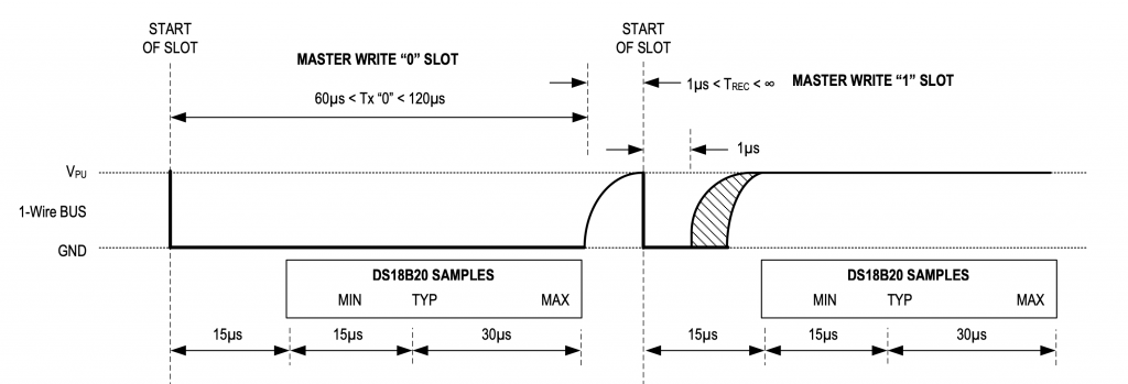
The one wire protocol has the following steps.
In order to write a “0” you need to
- Pull down the bus (write a 0)
- Wait 60uS
- Write a 1
- Wait 1uS (to allow the next “slot” to start
In order to write a “1” you need to
- Pull down the bus (write a 0)
- Wait 1 uS
- Write a 1
- Wait 60uS (to allow the next “slot” to start)
Notice that the minimum write slot is 60uS and the maximum is 120uS. Here is a picture from the data sheet.
For the first implementation of owb_write_bit I will use a simple “CyDelayUs” to implement the delays (this is a bad idea, but is a ‘cheap’ way to get going).
owb_ret_t owb_write_bit(OneWireBus *bus,uint8_t val)
{
    owb_ret_t rval = OWB_STATUS_OK;
    cyhal_gpio_write(bus->pin,0);
    if(val == 0)
    {
        CyDelayUs(60);
        cyhal_gpio_write(bus->pin,1);
        CyDelayUs(2);

    }
    else
    {
        CyDelayUs(1);
        cyhal_gpio_write(bus->pin,1);
        CyDelayUs(60);
    }
    return rval;
}
The write byte function just loops through the 8-bit and uses the owb_write_bit function. Notice that it is least significant bit first.
owb_ret_t owb_write_byte( OneWireBus *bus, uint8_t val)
{
    owb_ret_t ret = OWB_STATUS_OK;
    for(int i=0;i<8;i++)
    {
        ret = owb_write_bit(bus,(val>>i) & 0x01);
        if(ret != OWB_STATUS_OK)
            return ret;
    }
    return OWB_STATUS_OK;
}
And write_bytes (multiple) just loops through the buffer calling the write_byte function.
owb_ret_t owb_write_bytes( OneWireBus *bus, uint8_t *buffer, uint32_t length)
{
    owb_ret_t ret = OWB_STATUS_OK;
    for(int i=0;i<length;i++)
    {
        ret = owb_write_byte(bus,buffer[i]);
        if(ret != OWB_STATUS_OK)
            return ret;
    }
    return OWB_STATUS_OK;
}
Now that I have the three write functions I will add a new command to usrcmd.c This function lets the user type a command like “wbyte a1” where he/she can input a 2-character hex command. Yes, I use the sscanf function which is unsafe… but cheap for a test rig.
static int usrcmd_wbyte(int argc, char **argv)
{
    if(argc != 2)
    {
        printf("Invalid argument write  %d\n",argc);
        return 0;
    }

    owb_ret_t ret=OWB_STATUS_OK;

    int val;
    sscanf(argv[1],"%02x",&val);

    printf("Write Byte Val = %02X\n",val);

    ret = owb_write_byte(&bus,(uint8_t)val);

    if(ret == OWB_STATUS_OK)
        printf("Write byte succeeded\n");
    else
        printf("Write byte failed\n");


    return 0;
}
When I program and launch the project I end up here.
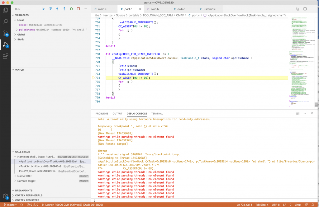
OK that is easy enough to fix, I just ran out of stack in the ntshell thread.
xTaskCreate(ntShellTask, "nt shell task", configMINIMAL_STACK_SIZE*3,0 /* args */ ,0 /* priority */, 0);
Now when I run it I am off to the races.
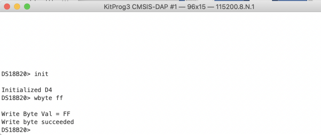
Here is an example of “wbyte ff”
What about “owb_write_rom_code”? I don’t know what it does, but Ill figure it out as I integrate the rest of the library.
Read
When I examine the ds18b20.c file I find these three read functions, which mirror the write functions.
owb_ret_t owb_read_bit( OneWireBus *bus, uint8_t *bit);
owb_ret_t owb_read_byte( OneWireBus *bus, uint8_t *byte);
owb_ret_t owb_read_bytes( OneWireBus *bus, uint8_t *buffer, uint32_t length);
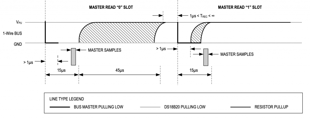
To read a bit you follow a a very similar process to the write.
- Write a 0 on the bus
- Wait 1uS
- Write a 1 on the bus (release the bus)
- Wait 5uS
- Read (the slave will pull a 0 or a 1 onto the bus)
- Wait 55uS to the end of the slot
Here is a picture
The code uses a really bad busy-wait delay (but it is a good starting place to figure out what is happening)
owb_ret_t owb_read_bit( OneWireBus *bus, uint8_t *bit)
{
    owb_ret_t rval = OWB_STATUS_OK;

    cyhal_gpio_write(bus->pin,0);
    CyDelayUs(1);
    cyhal_gpio_write(bus->pin,1);
    CyDelayUs(5);

    *bit = cyhal_gpio_read(bus->pin);
    CyDelayUs(55);
    return rval;
}
To read a byte, just read 8 bits using the owb_read_bit function
owb_ret_t owb_read_byte( OneWireBus *bus, uint8_t *byte)
{
    uint8_t bit;
    owb_ret_t ret = OWB_STATUS_OK;

    *byte = 0;
    for(int i=0;i<8;i++)
    {
        ret = owb_read_bit(bus,&bit);
        if(ret != OWB_STATUS_OK)
            return ret;
        *byte = *byte | (bit<<i);
    }
    return OWB_STATUS_OK;
}
To read an array of bytes, use a loop of read_byte
owb_ret_t owb_read_bytes( OneWireBus *bus, uint8_t *buffer, uint32_t count)
{
    owb_ret_t ret = OWB_STATUS_OK;
    for(int i=0;i<count;i++)
    {
        ret = owb_read_byte(bus,&buffer[i]);
        if(ret != OWB_STATUS_OK)
            return ret;
    }
    return ret;
}
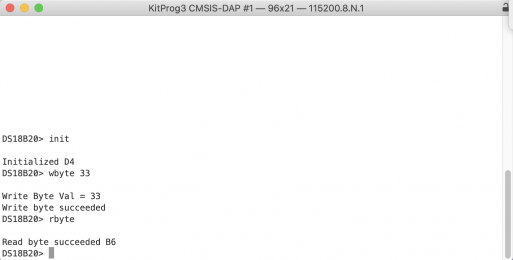
Now that you have a read and a write, update the usrcmd.c to add a “rbyte” command to the CLI
static int usrcmd_rbyte(int argc, char **argv)
{

    owb_ret_t ret=OWB_STATUS_OK;

    uint8_t val;

    ret = owb_read_byte(&bus,&val);

    if(ret == OWB_STATUS_OK)
        printf("Read byte succeeded %02x\n",val);
    else
        printf("Read byte failed\n");


    return 0;
}
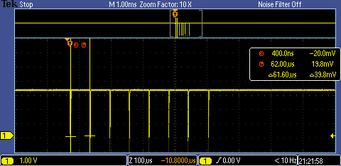
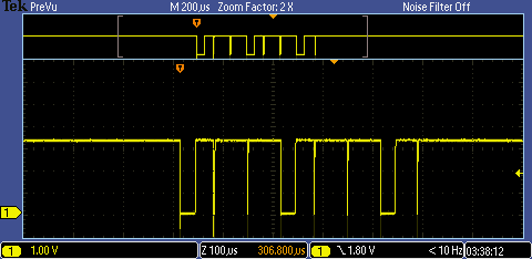
When I program the kit I can send a 0x33 (which will make the sensor respond more on this later), then read the first byte of the ROM
When you look at the scope picture (from right to left) you can see 10110110 which sure enough is B6. The thin gaps are 1’s and the wide gaps are 0’s
In the next article Ill deal with the stupid CyDelay’s
No comment yet, add your voice below!