Summary
As many of you have noticed, www.elkhorn-creek.org has been offline for quite a while (actually since December 22,2018). I know that many of you have really missed knowing how much water is in the creek. Given that it blew up in December, and I knew that I was going to have to crawl into the muddy creek to fix it, I had not gotten around to it. But, now it is July and the water is nice, so I don’t have much of an excuse. I have written extensively about my system, in fact, it was my first real IoT project. I assumed that it would not be that hard to fix. Boy was I wrong.
In this article I will:
- Get the Sensor out of the Elkhorn Creek & Debug
- Update the PSoC Project to use a Different GPIO
- Blow up the CyPi Power Supply
- Debug the Wrong Pressure Sensor
- Turn the Raspberry Pi Back on and Retest
Get the Sensor out of the Creek and Debug
I felt like Stanley in the Congo heading down the path to the Elkhorn Creek.

But, when you get there, look how beautiful it is.

Here is a picture looking down at the sensor setup from the top of the bank (that is a 6 foot ladder, so that bank is something like 10 feet high)
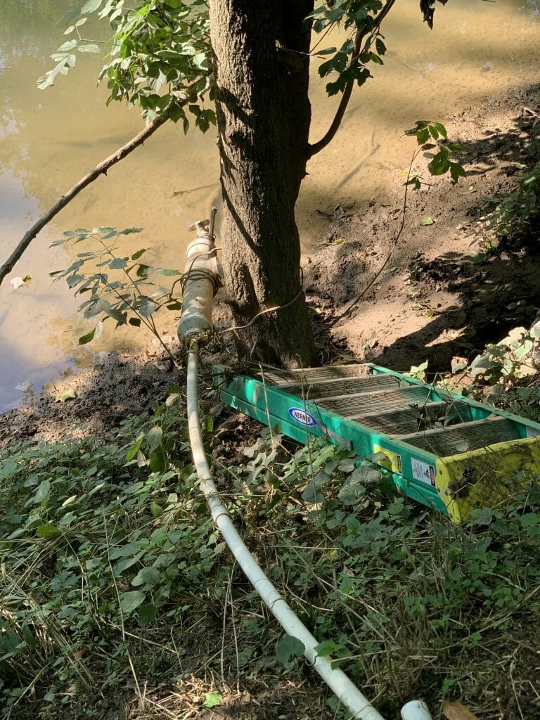
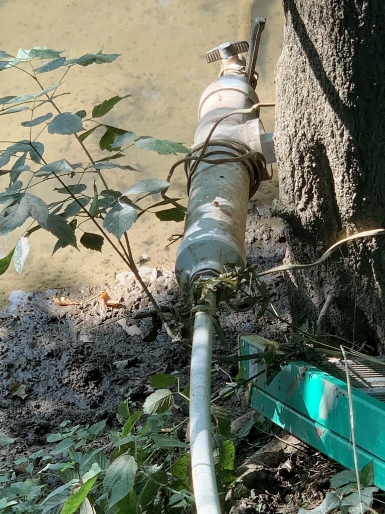
When you slide down the bank onto the ladder, this is where you end up. After I jumped off the ladder into the creek, I was in mud up to my knees. I had assumed that the problem was that water had leaked around sensor NPT connection. You can see the drain valve that I installed to drain water out of the pipe for just that case. When I opened the valve, there was no water… like none. This made me start to wonder what was going on. The sensor is installed in the end of that square clear out.
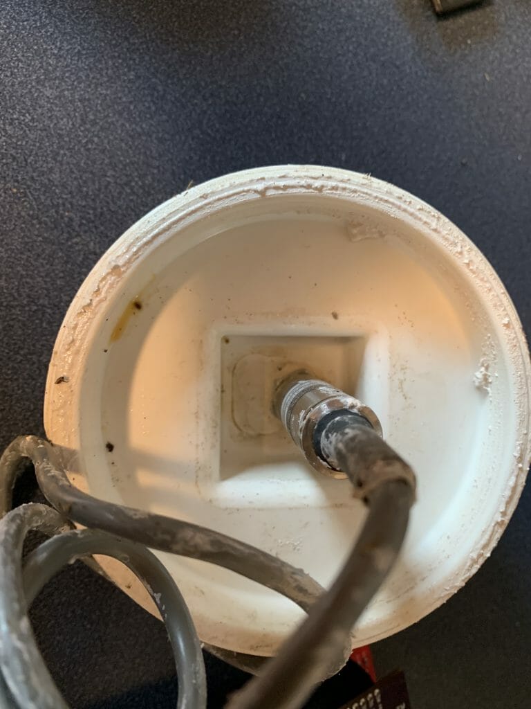
When I undid the sensor and brought it up into my lab, there was no leaking around the sensor. My original theory that the sensor had gotten water onto the dry side was incorrect.
So, I plugged the sensor in on my bench to try to figure out what was going on.
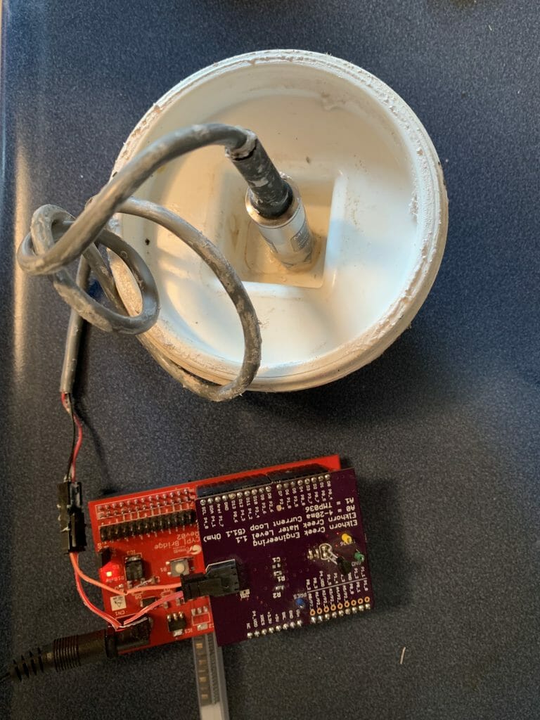
The first measurement I took was across the 51.1 ohm sensor resistor. Last time I checked, V=IR, so this means that it is drawing 133mA. That is bad given that it is a 4-20mA current loop.
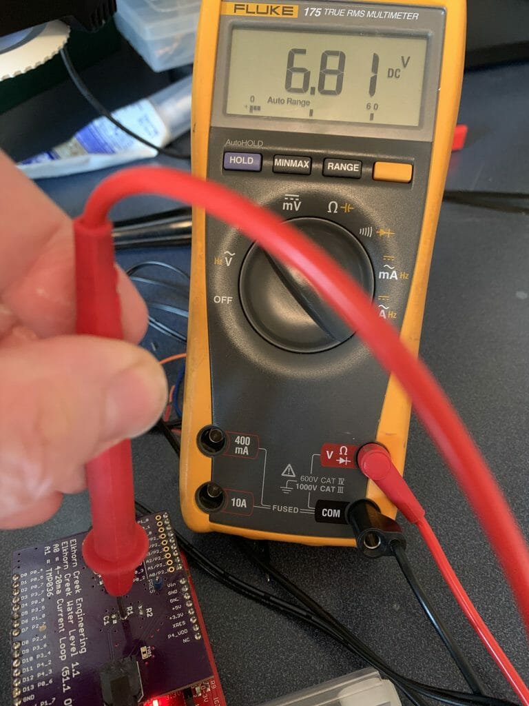
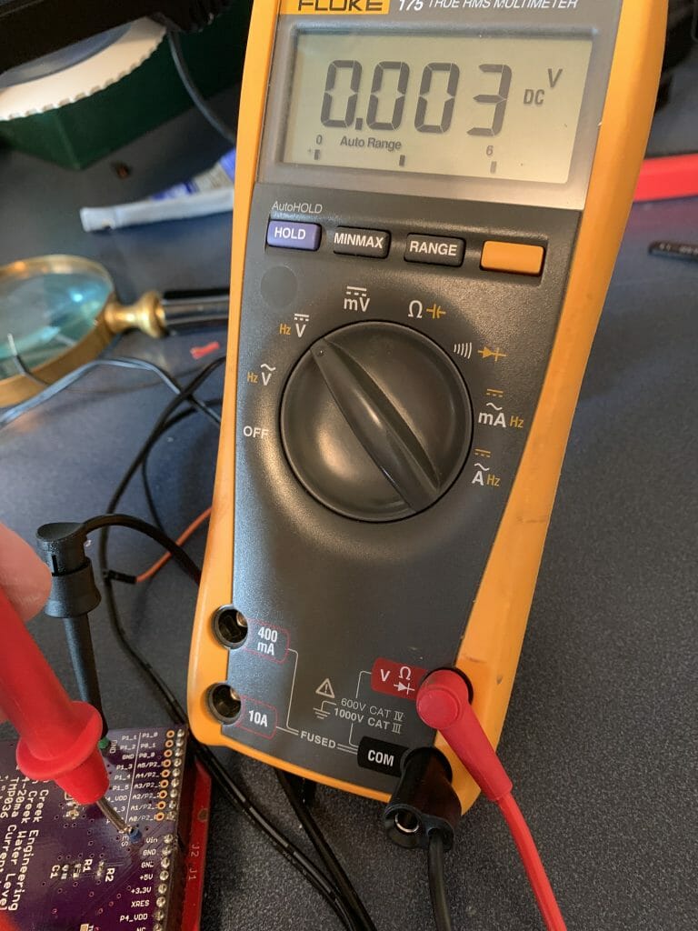
It is also bad to put 6.81V onto a PSoC pin. When I measure the voltage at the pin it is 0.003 V. Dead. At this point, I suspect that whatever killed the sensor also killed the PSoC, but I don’t know. I suppose that the sensor could have blown up (maybe an ESD event) and then when the voltage went to 6.81, it blew up the PSoC? I suppose that I will never know.
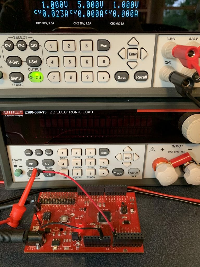
In fact, when I connect the power supply directly to the A0/P2[0] analog input, I get 0.023A … which means that I also blew up the GPIO and it is now shorted to ground. Well, actually it isn’t a short, it is more like 43 Ohm resistor. Bad.
Here is the spec from the PSoC 4 data sheet. 2mA is a long long way from 2nA.

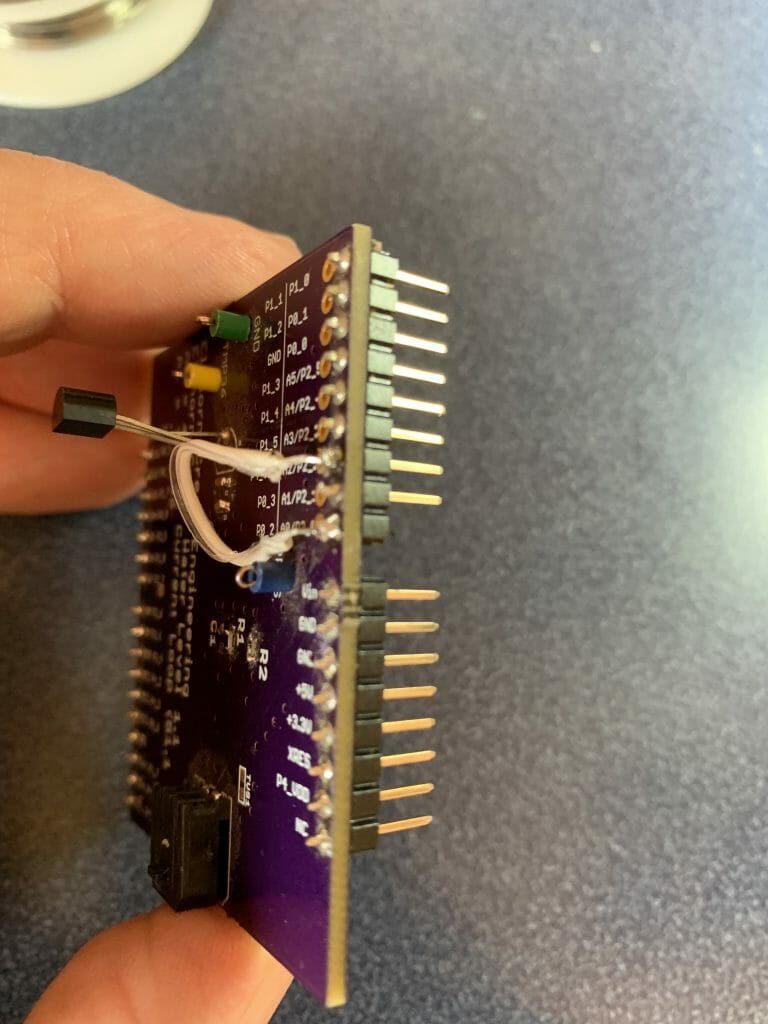
Unfortunately, this is the only CyPi board that I have. Moreover, I don’t have another PSoC4 chip to fix it with (or at least at my house right now). So, I decided that I will assume that the other pins are OK and I will use PSoC Creator to move to another pin (A2) that hopefully isn’t blown up. To do this, I snip off the Arduino pin, then solder a jumper on the top from A0 to A2.
Update the PSoC Project to use a Different GPIO
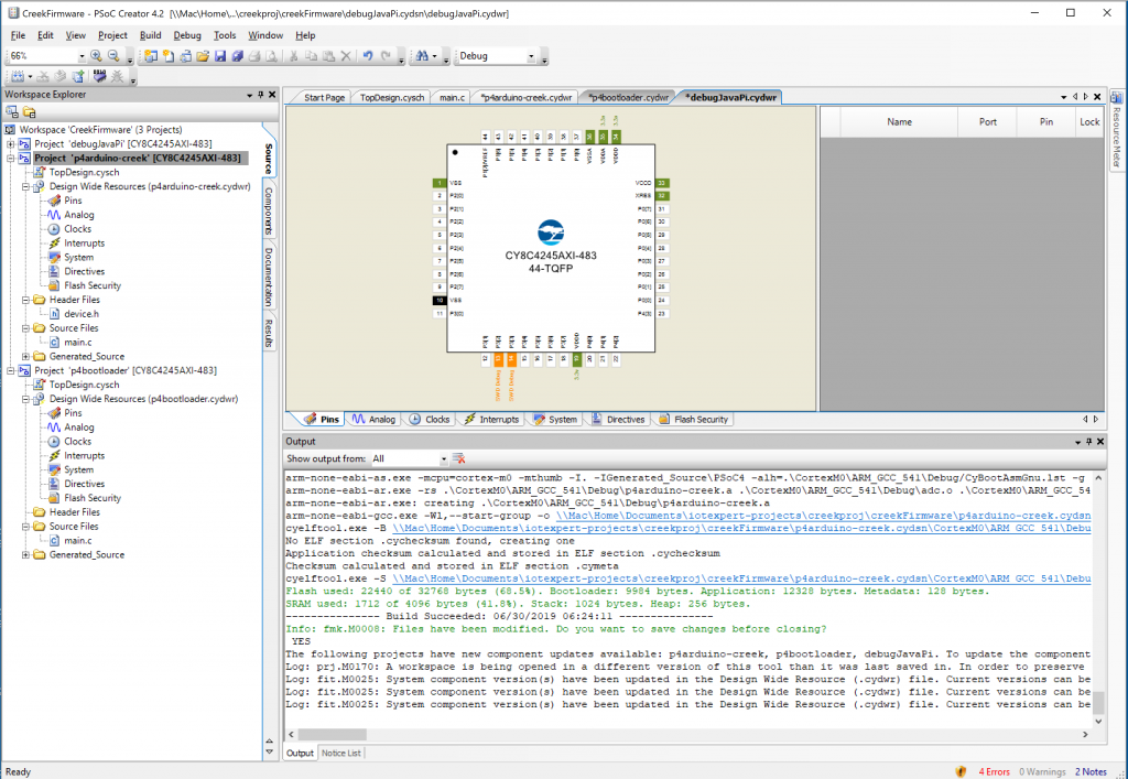
Next, I have to fix the firmware to use A2 instead of A0. This is AKA P2[2] instead of P2[0]. When I open up the workspace in PSoC Creator, it immediately starts complaining about components that are old. Notice that all of the “dwr’s” which are opened have an asterisk indicating they have changed. In order to fix this I need to update all of the components.
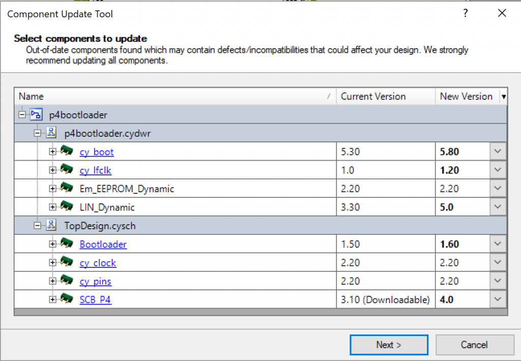
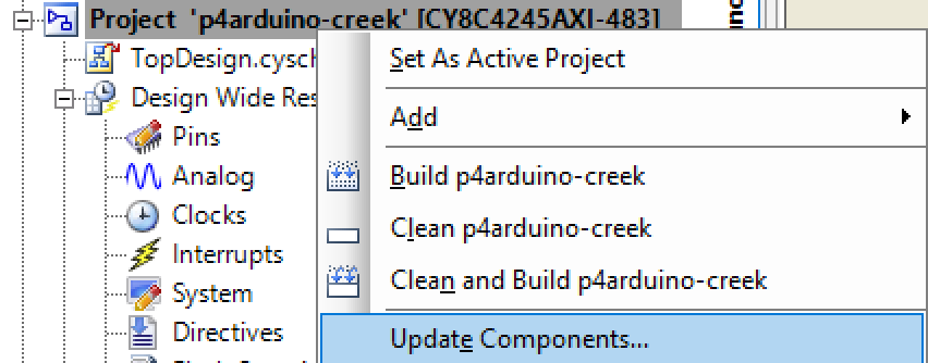
Starting with the boot loader project called “p4bootloader”, right click and select “Update Components…”

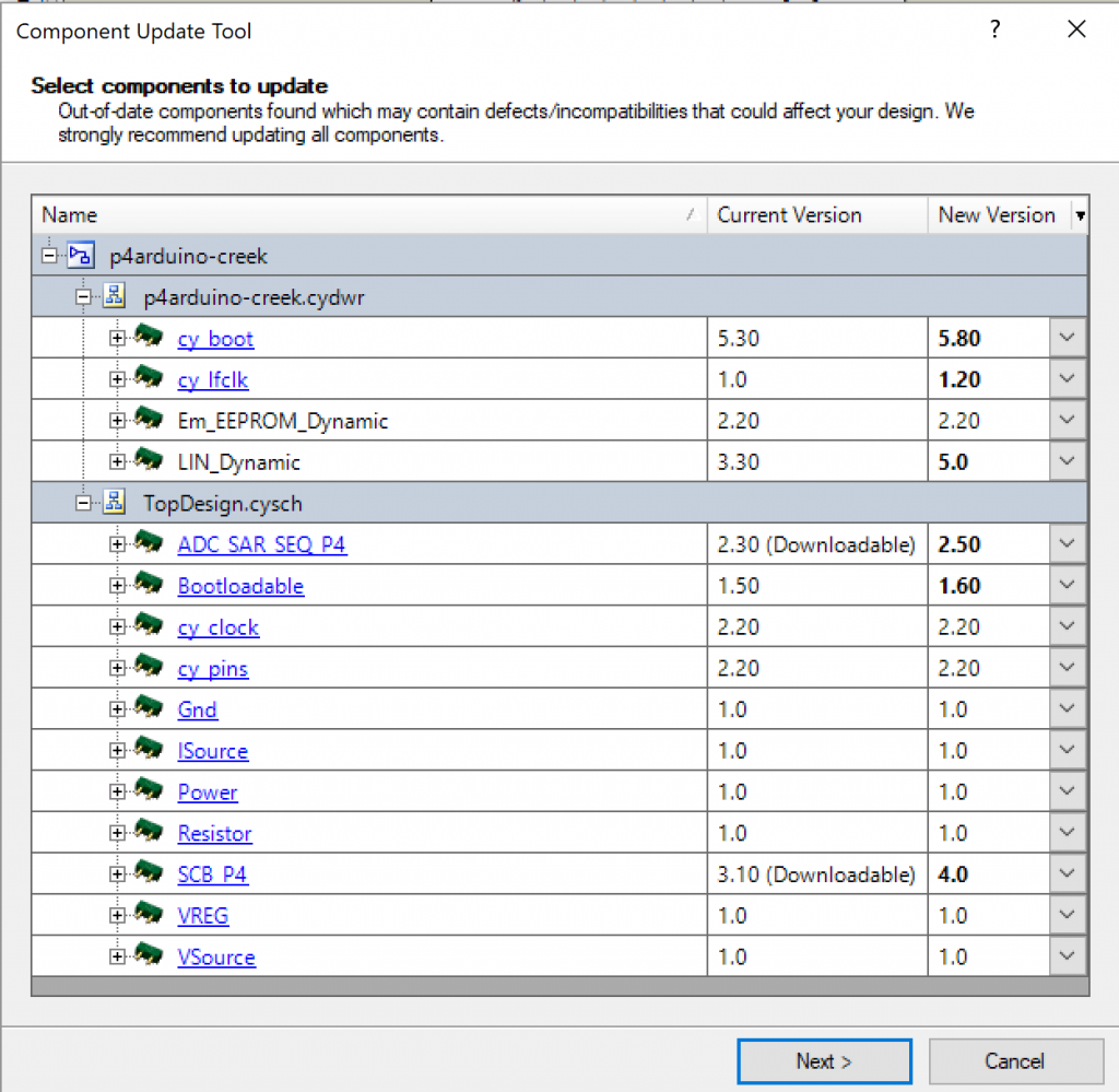
Notice that eight of the components in the project are old. Select Next.
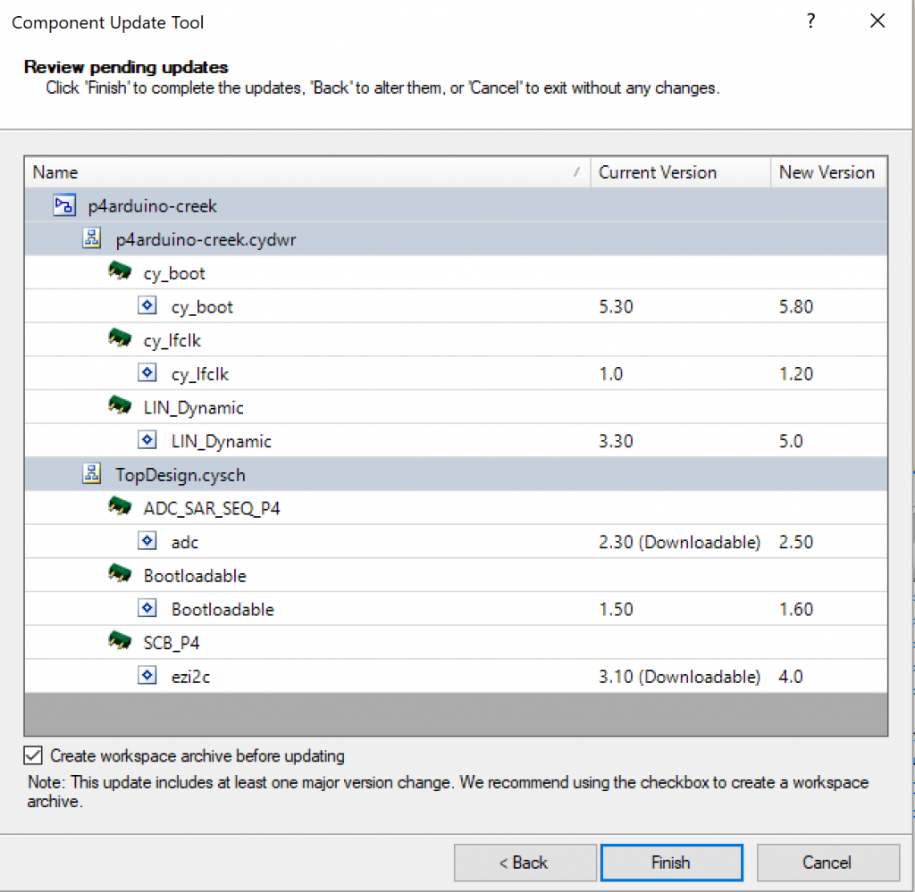
Then turn off the “create a workspace archive before updating option”. My project is in Git so I don’t need to save it in case something bad happens. Then click Finish.
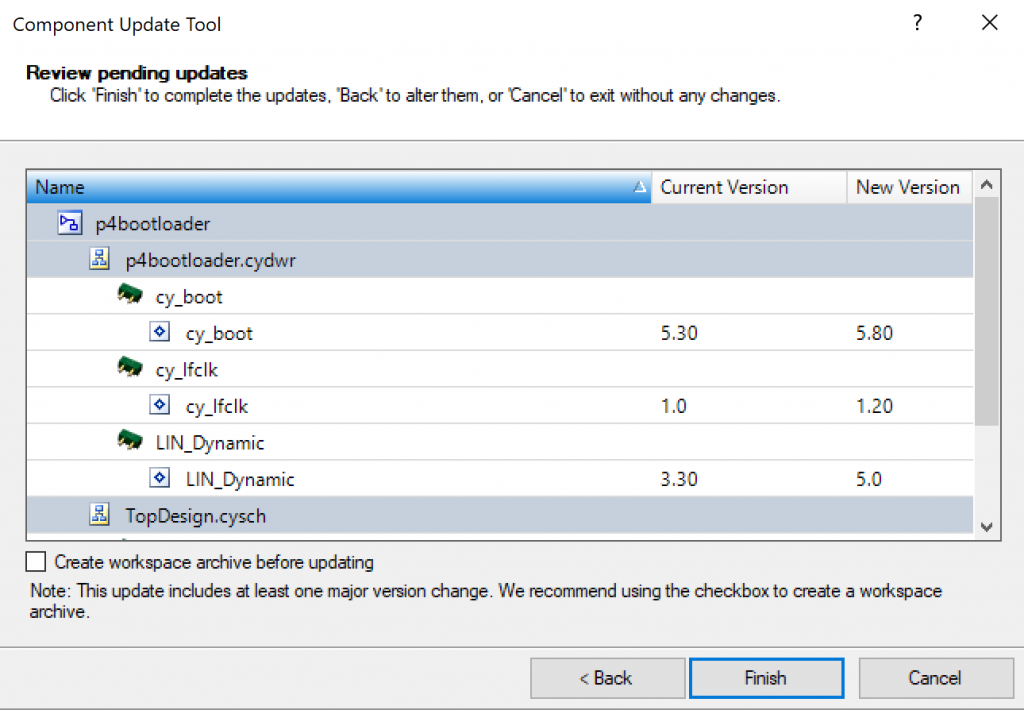
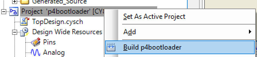
And after a minute I can Build the project.
Next I update the main project which is called “p4arduino-creek”
Follow the same process as before:
In this case I forget to click the archive button, but I can cancel the archive.
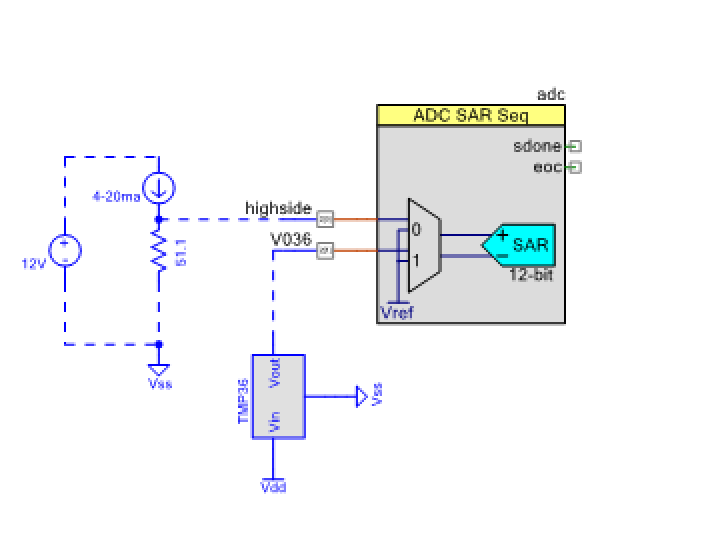
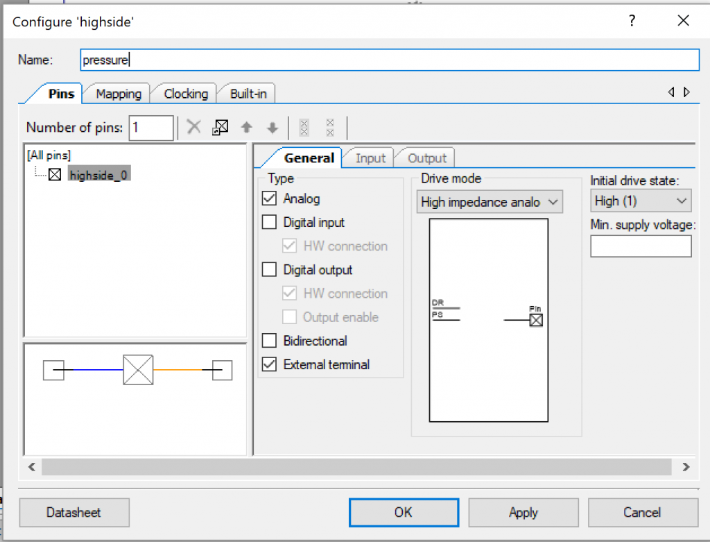
Once the update is done, look at the schematic. The first thing that I notice is that I called the pressure input “high side”. I hate the name high side… so I am going to fix it to be called pressure
Double click the pin and change it to “pressure”
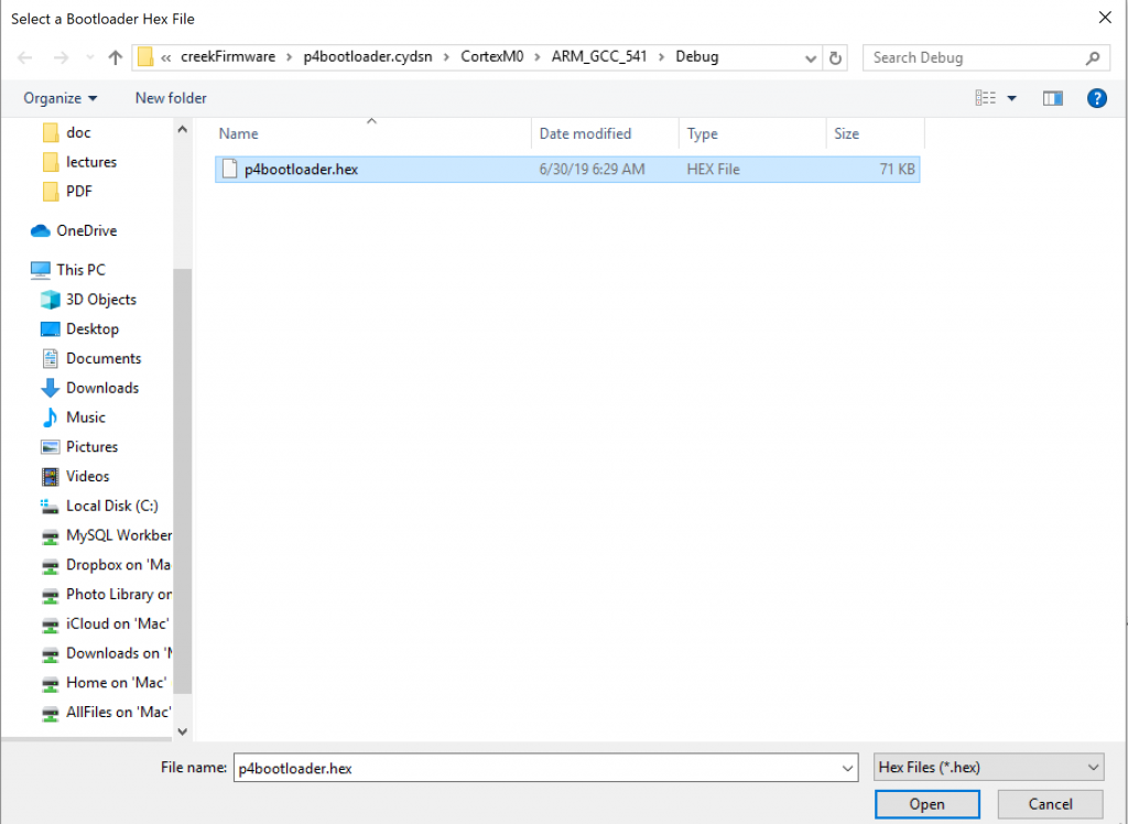
Because the boot loader hex changed, I need to update the reference in the bootloadable component. Double click it and correct the path.
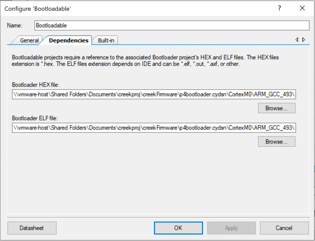
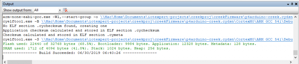
Notice that it has a new version of the compiler.
![]()
Then reassign the pressure pin to be P2[2] which is also known as A2
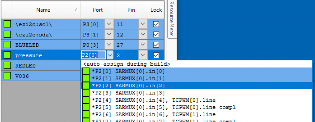
Then rebuild and notice that everything is OK.
Once I reprogram the board, I take it outside to reinstall the whole mess. After I hook it up I start probing with the multimeter and immediately short out the power supply with one of the multi-meter probes.
Blow up the CyPi Power Supply
Which blows up the REG1117. Here is an animated GIF where you can see that it turns on.. then immediately goes off. This is more than a little bit annoying.
Fortunately, I have my original CyPi prototype. So, I go back to the prototype CyPi – which means that I have to use two power supply connections. One of the things that I fixed in the final CyPI was to have the ability to drive the Raspberry Pi with the 12V input (I have ordered a new REG 1117).
Debug the Wrong Pressure Sensor
When I install everything, an unbelievably frustrating thing happens. I put the probe on the sensor and I immediately measure 1.007V which is 19.7 mA which is also known as 14.7346 PSI. This is seriously bad. I have been standing in mud up to my knees fixing the damn system and it is already broken again. I should be measure 4mA*51.ohm = .202V. But no. This was a deeply frustrating moment because I assumed that something else is wrong with my system.
When I got back inside and tried to figure out what in the world was happening, I thought, maybe the pressure sensor is clogged or something? This made me wonder what the air pressure in Kentucky at that moment was. After a little bit of google I find that the air pressure is 30 inches of Hg… which turns out to be … guess… 14.7 PSI. I knew immediately that I purchased the WRONG DAMN SENSOR.
Measurement Specialties makes the US381 in both Gauge and Absolute pressure. In the Absolute case, it gives you the pressure with a reference to a vacuum. In the gauge case it gives you a relative measurement. The back side of this pressure sensor is exposed to the air, which lets it cancel out atmospheric pressure changes. But I bought US381-000005-015PA instead of the correct US381-000005-015PG.

And, a few days later Mouser delivered me the correct sensor, and after and hour of mud and sweat I had things ready to try again.
Turn the Raspberry Pi Back on and Retest
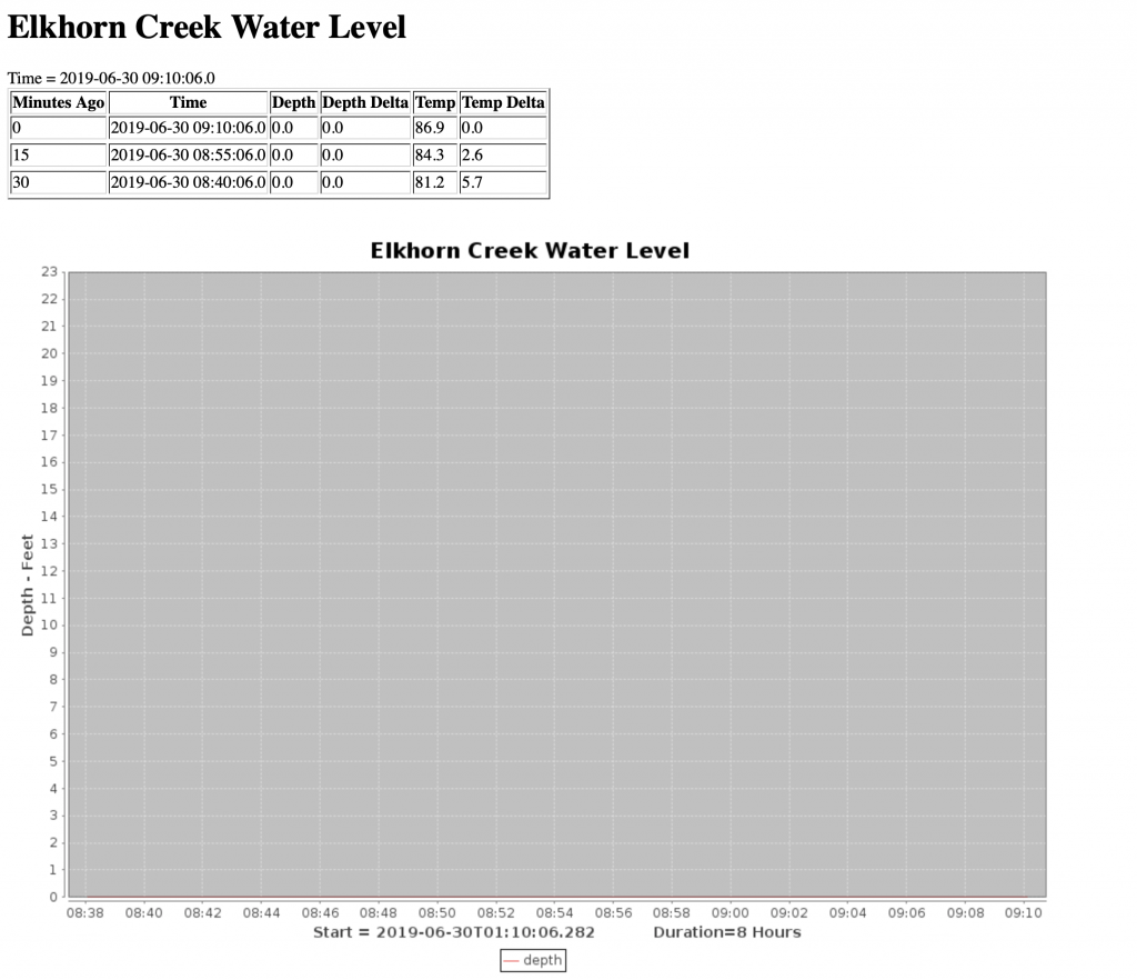
After re-installing everything in the barn, I now get .202V across the 51.1 Ohm Sensor Resistor, which means that I am getting exactly 4mA. That makes perfect sense as right now the pressure sensor is just exposed to the air. (meaning it is sticking out of the water)
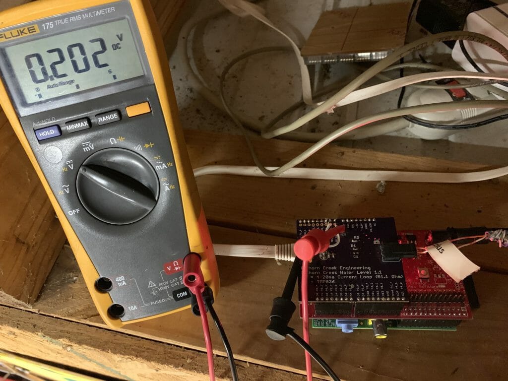
And now www.elkhorn-creek.org is working again. Good.
No comment yet, add your voice below!