The Creek 2.0: AWS IoT Actions & Rules

Summary

In this article, I will show you how to use the AWS IoT rules engine to make the last connection required in the chain of data from the Creek Sensor all the way to the AWS RDS Server.  I will also show you the AWS CloudWatch console.  At this point I have implemented

Let’s implement the final missing box (6) – The AWS IoT Rules

The AWS Rules

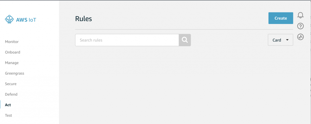
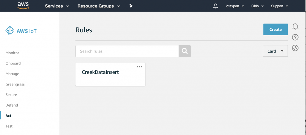
Start by going to the AWS IoT Console.  On the bottom left you can see a button named “Act”.  If you click Act…

You will land on a screen that looks like this.  Notice, that I have no rules (something that my wife complains about all of the time).  Click on “Create” to start the process of making a rule.

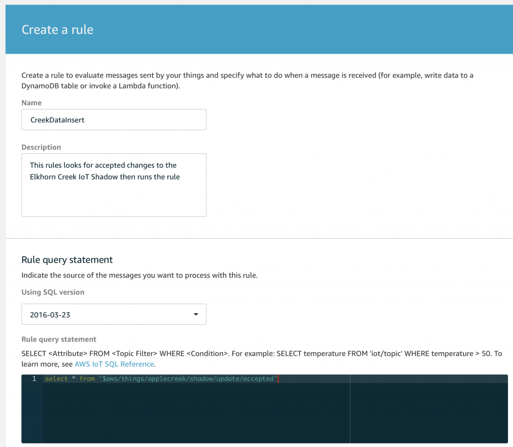
On the create rule screen I will give it a name and a description.  Then, I need to create a “Rule query statement“.  A rule query statement is an SQL like command that is used to match topics and conditions of the data on the topic.  Below, you can see that I tell it to select “*” which is all of the attributes.  And then I give it the name of the topic.  Notice that you are allowed to use the normal MQTT topic wildcards # and + to expand the list to match multiple topics.

Scroll down to the “Set one or more actions” and click on “add action”

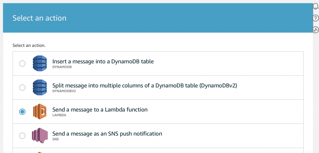
This screen is amazing as there are many many many things that you can do.  (I should try some of the others possibilities).  But, for this article just pick “Send a message to a Lambda function”

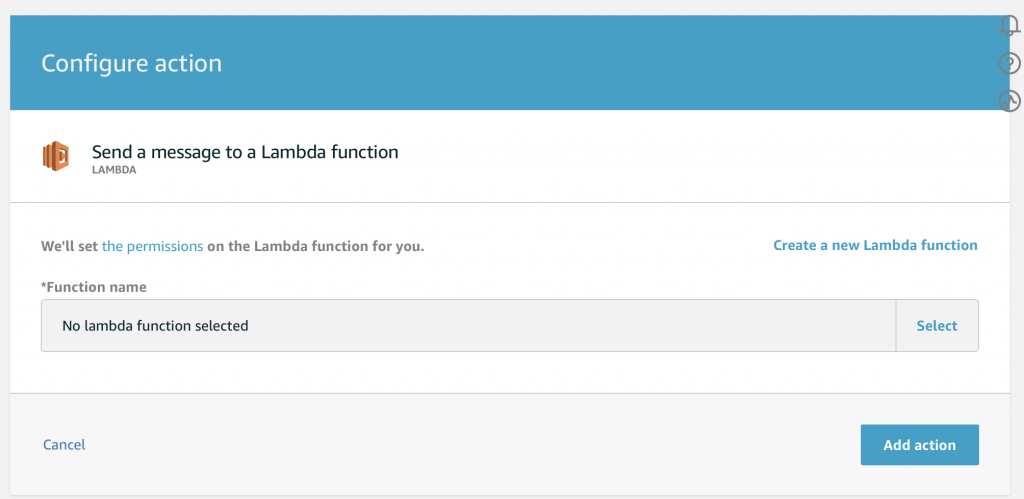
Then press “Select” to pick out the function.

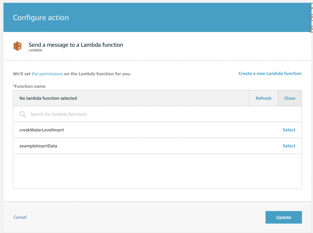
Then you will see all of your Lambda functions.  Ill pick the “creekWaterLevelInsert” which is the function I created which takes the json data and inserts it into my AWS RDS MySQL database.

Once you press “Update”, you will see that you have the newly created rule…

The Test Console

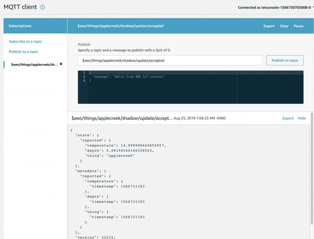
Now that the rule is setup.  Let’s go to the AWS MQTT Test Client and wait for an update to the “applecreek”  thing Shadow.  You might recall that when a shadow update message is published to $aws/things/applecreek/shadow/update if that message is accepted then a response will be published by AWS to $aws/things/applecreek/shawdow/update/accepted.

On the test console, I subscribe to that topic.  After a bit of time I see this message get published that at 7:06AM the Apple Creek is 0.08.. feet and the temperature in my barn is 14.889 degrees.

But, did it work?

 AWS Cloud Watch

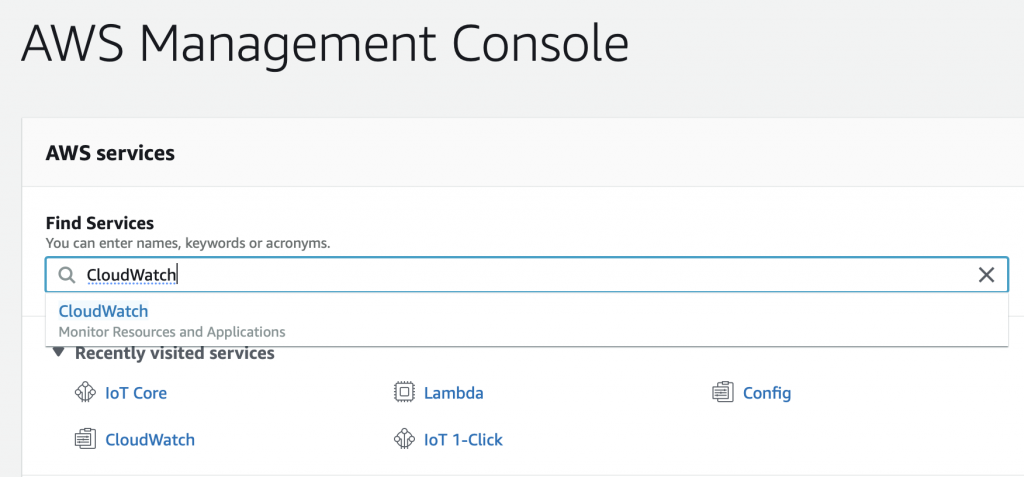
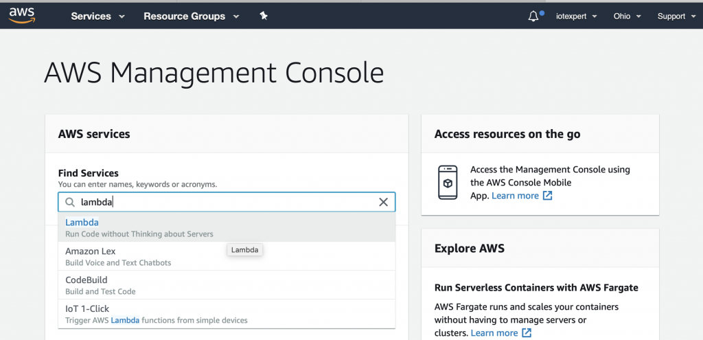
There are a couple of ways to figure this out.  But, I start by going to AWS CloudWatch which is the AWS consolidator for all of the error logs etc.  To get there search for “CloudWatch” on the AWS Management Console.

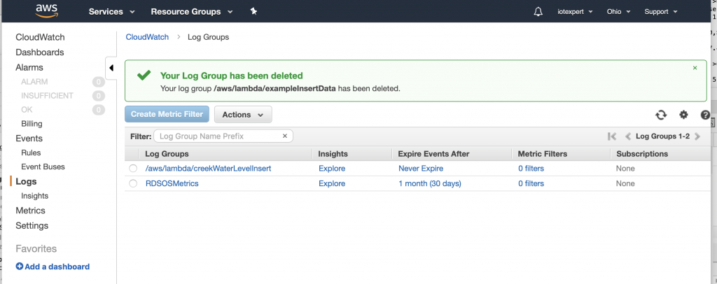
Then click on “logs”.  Notice that the log at the top is called “…/creekWaterLevelInsert”.   As best I can tell, many things in AWS generate debugging or security messages which go to these log files.

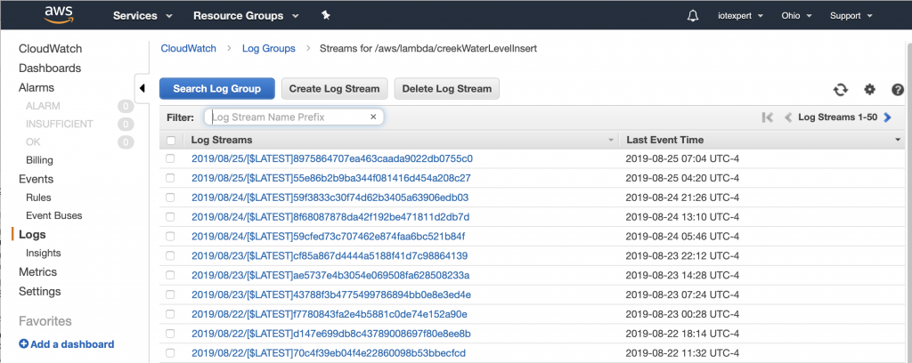
If you click on the /aws/lambda/creekWaterLevelInsert you can see that there are a bunch of different log streams for this Lambda Function.  These streams are just ranges of time where events have happened (I have actually been running this rule for  a while)

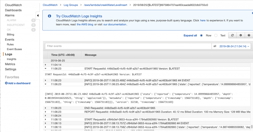
If I click on the top one, and scroll to the bottom you can see that at “11:06:23” the function was run.  And you can see the JSON message which was sent to the function.  You might ask yourself 11:06 … up above it was 7:06… why the 4 hours difference.  The answer to that question is that the AWS logs are all recorded in UTC… but I save my messages in Eastern time which is  current UTC-4.  (In hindsight I think that you should record all time in UTC)

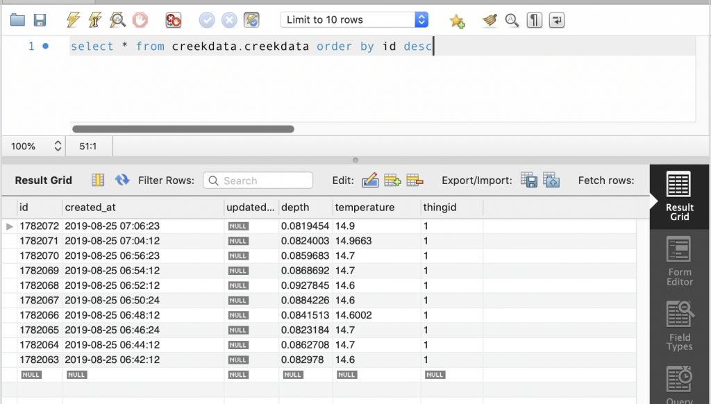
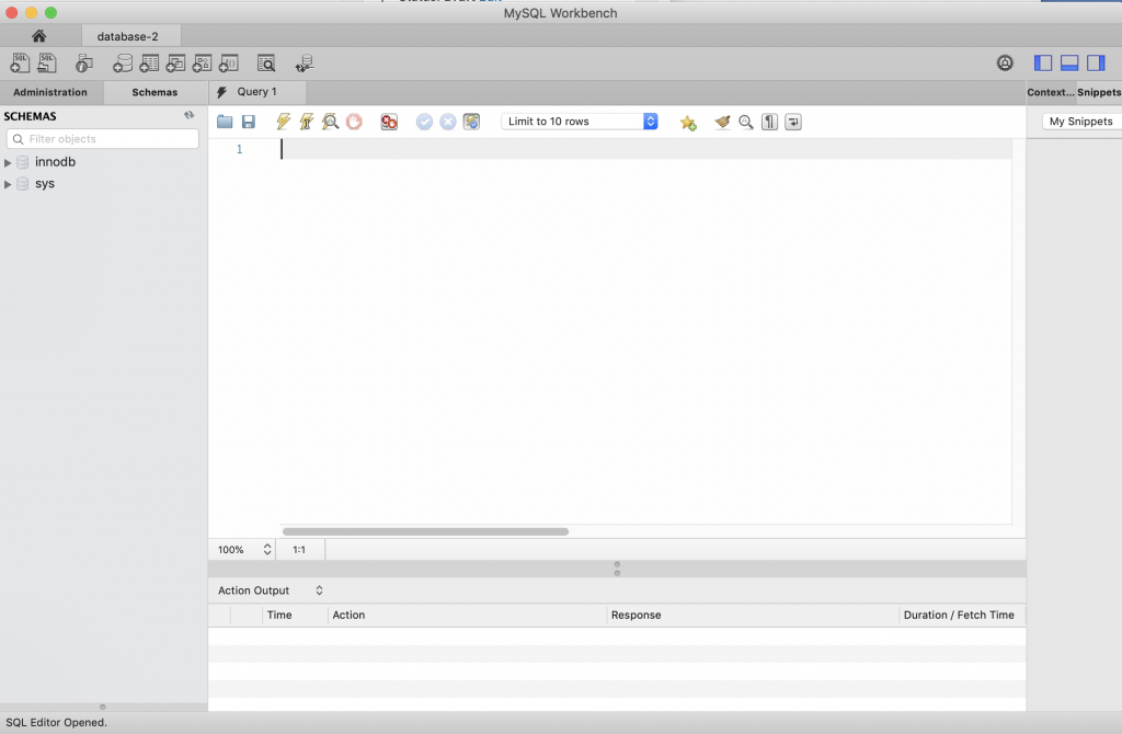
The real way to check to make sure that the lambda function worked correctly is to verify that the data was inserted into my RDS MySQL database.  To find this out I open up a connection using MySQL WorkBench (which I wrote about here).  I ask it to give me the most recent data inserted into the database and sure enough I can see that at 7:06 the temperature was 14.9 and the depth was 0.08… sweet.

For now this series is over.  However, what I really need to do next is write a web server that runs on AWS to display the data… but that will be for another day.

The Creek 2.0: AWS Lambda Function

Summary

At this point in the Creek 2.0 series I have data that is moving from my sensor into the AWS IoT core via MQTT.  I also have a VPC with an AWS RDS MySQL database running.  In order to get the data from the AWS IoT Device Shadow into the database, I am left with a two remaining steps:

  1. Create a Lambda Function which can run when asked and store data into the Database (this article)
  2. Connect the IoT MQTT Message Broker to the Lambda Function (the next article)

This article addresses the Lambda Function, which unfortunately is best written in Python.  I say ‘unfortunately’ because I’ve always had enough self-respect to avoid programing in Python – that evil witch’s brew of a hacker language.  🙂  But more seriously, I have never written a line of code in Python so it has been a bit of a journey.  As a side note, I am also interested in Machine Learning and the Google TensorFlow is Python driven, so all is not lost.

For this article, I will address:

  1. What is an AWS Lambda Function?
  2. Create a Lambda Function
  3. Run a Simple Test
  4. Install the Python Libraries (Deployment Package)
  5. Create a MySQL Connection and Test
  6. Configure the Lambda Function to Run in your VPC
  7. Create an IAM Role and Assign to the Lambda Function
  8. Update the Lambda Function to Insert Data
  9. The Whole Program

What is an AWS Lambda Function?

AWS Lambda is a place in the AWS Cloud where you can store a program, called a Lambda Function.  The name came from the “anonymous” function paradigm which is also called a lambda function in some languages (lisp was the first place I used it).  The program can then be triggered to run by a bunch of different things including the AWS IoT MQTT Broker.  The cool part is that you don’t have to manage a server because it is magically created for you on demand.   You tell AWS what kind of environment you want (Python, Go, Javascript etc), then AWS automatically creates that environment and runs your Lambda function on demand.

In this case, we will trigger the lambda function when the AWS IoT Message Broker accepts a change to the Device Shadow.  I suppose that the easiest way to understand is to actually build a Lambda Function.

Create a Lambda Function

To create a Lambda function you will need to go to the Lambda management console.  To get there, start on the AWS Management console and search for “lambda”

On the Lambda console, click “Functions” then “Create function”

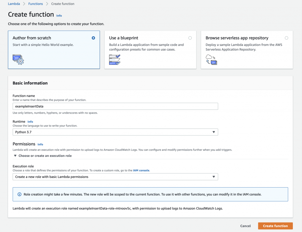
We will build this function from scratch… oh the adventure.  Give the function a name, in this case “exampleInsertData”.  Finally, select the Runtime.  You have several choices including “Python 3.7” which I suppose was the lesser of evils.

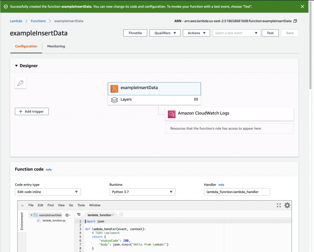
Once you click “Create function” you will magically arrive at this screen where you can get to work.  Notice that the AWS folks give you a nice starter function.

Run a Simple Test

Now the we have a simple function let us run a simple test – simple, eh?  To do this, click on the drop down arrow where it says “Select a test event” and then pick out “Configure test events”

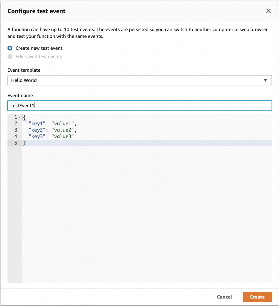
On the configure test event screen,  just give your event the name “testEvent1” and click “Create”

Now you can select “testEvent1” and then click “Test”

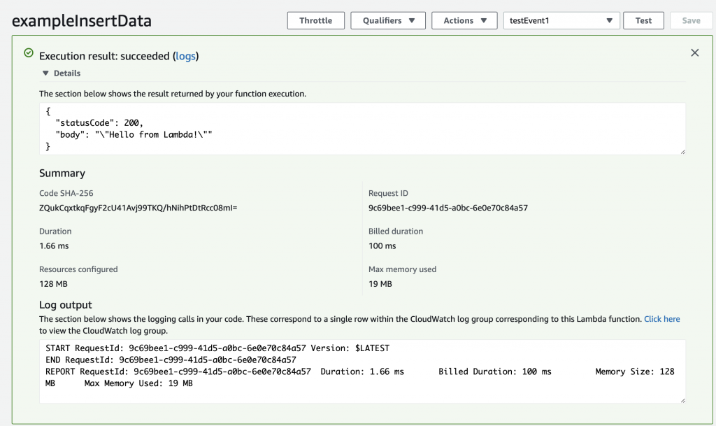
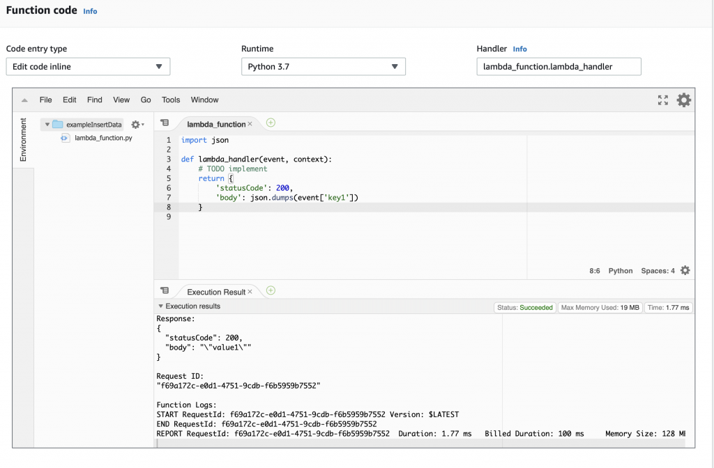
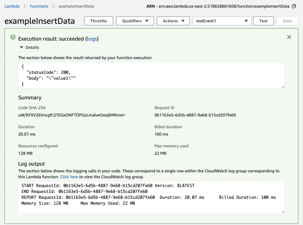
This will take the JSON message that you defined above (actually you let it be default) and send it into the Lambda program.  The console will show you the output of the whole mess in the “Execution result: …”  Press the little “Details arrow” to see everything.  Notice that the default function sends a JSON keymap with two keys.

  • statusCode
  • body

When you function runs, an object is created inside of your Python program called “event” that is the JSON object that was sent to the Lambda function.  When we created the testEvent1 it gave us the option to specify the JSON object which is used as the argument to the function.  The default was a keymap with three keys key1,key2 and key3.

{
  "key1": "value1",
  "key2": "value2",
  "key3": "value3"
}

Instead of having the function return “Hello from Lambda” lets have it return the value that goes with “key1”.  To do that, make a little modification to the function to “json.dumps(event[‘key1’])”.  Now when you run the test you can see that it returns the “body” as “value1”.

Install Python Libraries

The default installation of Python 3.7 in Lambda does not have two libraries that I want to use.  Specifically:

  • pymysql – a MySQL database interface
  • pytz – a library for manipulating time (unfortunately it can’t create more time)

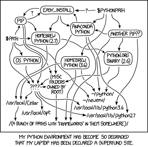
I actually don’t know what libraries are in the default Python3.7 runtime (or actually even how to figure it out?).  In order to use libraries which are not part of the Python installation by default, you need to create a “Python Deployment Package“.  If you google this problem, you will find an amazing amount of confusion on this topic.  The humorist XKCD drew a very appropriate cartoon about this topic.  (I think that I’m allowed to link it?  but if not I’m sorry and I’ll remove it)

Making a deployment package is actually pretty straightforward.  The steps are:

  1. Create a directory on your computer
  2. Use PIP3 to install the libraries you need in your LOCAL directory
  3. Zip it all up
  4. Upload the zip file to AWS Lambda

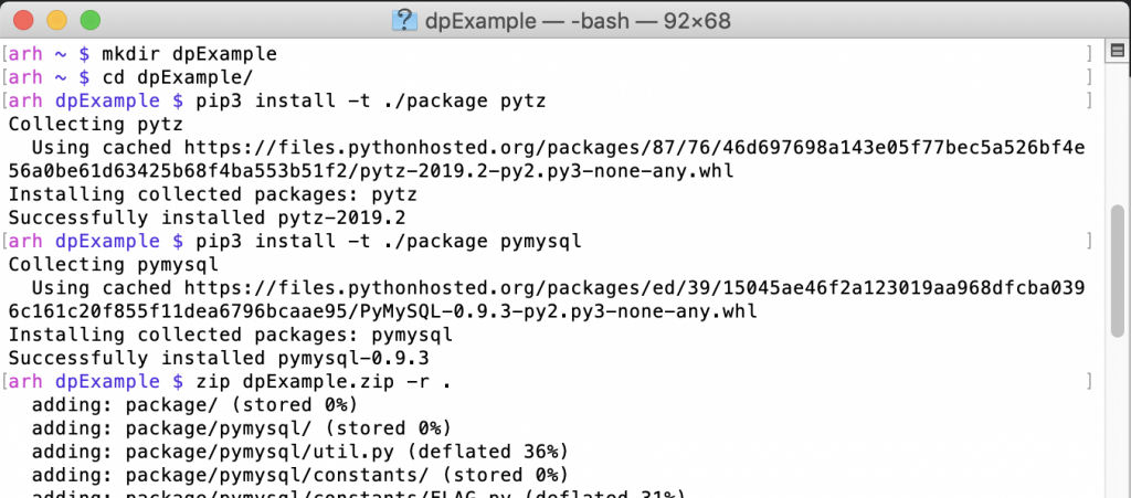
Here are the first three steps (notice that I use pip3)

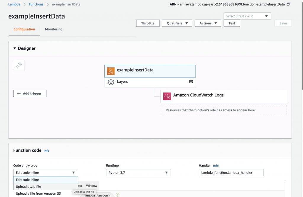
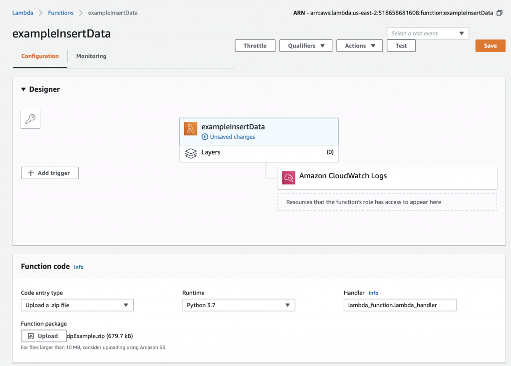
To update your AWS Lambda function, select “Upload a .zip file” on the Function code drop down.

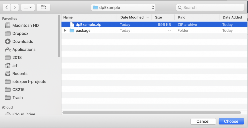
Then pick your zip file.

Now you need to press the “Save” button which will do the actual update.

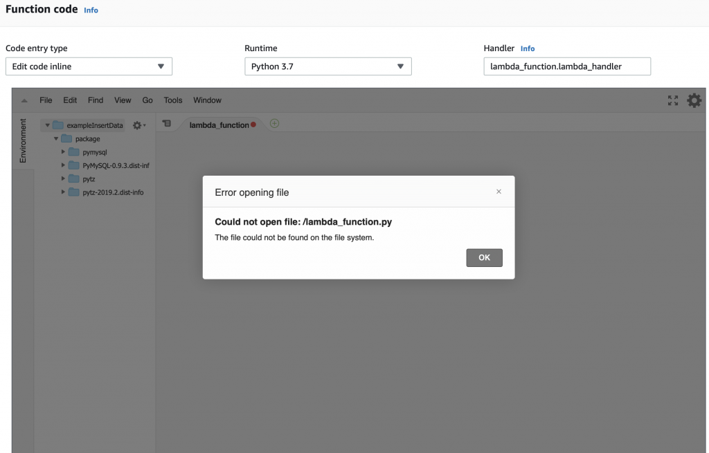
After the upload happens you will get an error message like this.  The problem is that you don’t have a file called “lambda_function.py” and/or that file doesn’t have a function called “lamda.handler”.  AWS is right, we don’t have either of them.

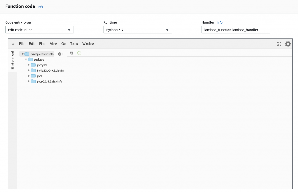
But you can see that we now have the “package” directory with the stuff we need to attach to the MySQL database and to manipulate time.

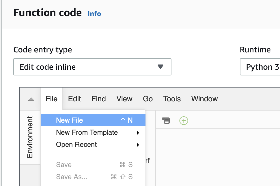
The little box that says “handler” tells you that you need to have a file called “lamda_function.py” and that Python file needs to have a function called “lambda_handler”.  So let’s create that file and function.  Start with “File->New File”

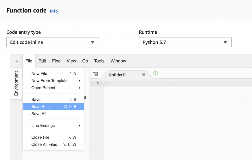
The a “File->Save As…”

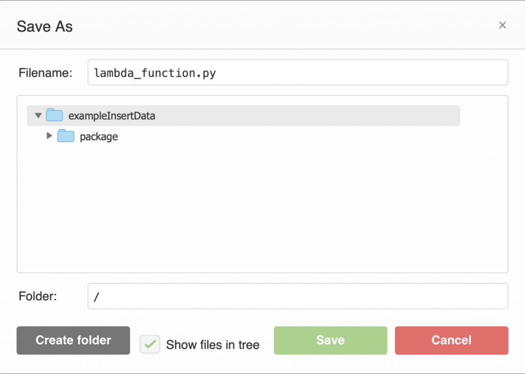
Give it the name “lambda_function.py”

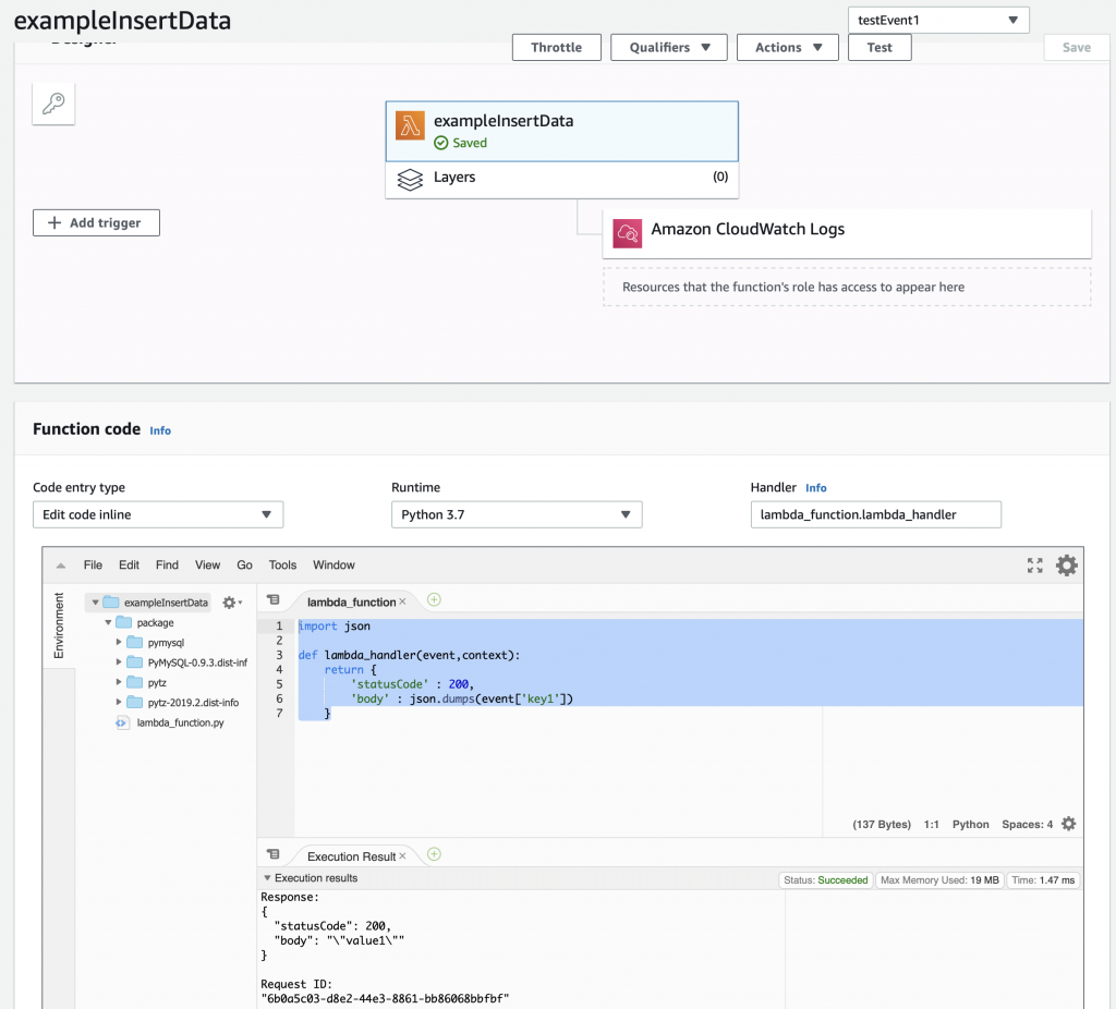
Now write the same function as before.  Then press “save”.  You could have created the function and file on your computer and then uploaded it as part of the zip file, but I didn’t.

import json

def lambda_handler(event,context):
    return {
        'statusCode' : 200,
        'body' : json.dumps(event['key1'])
    }

OK.  Let’s test and make sure that everything is still working.  So run the “testEvent1″… and you should see that it returns the same thing.

The next step is to create and test a MySQL connection.

Create a MySQL Connection and Test

This simple bit of Python uses the “pymysql” library to open up a connection to the “rds_host” with the “name” and “password”.  Assuming this works, the program goes on and runs the lambda_hander.  Otherwise it spits out an error to the log and exits.

import json
import logging
from package import pymysql


#rds settings
rds_host  = "your database endpoint goes here.us-east-2.rds.amazonaws.com"
name = "your mysql user name"
password = "your mysql password "
db_name = "your database name"

logger = logging.getLogger()
logger.setLevel(logging.INFO)

try:
    conn = pymysql.connect(rds_host, user=name, passwd=password, db=db_name, connect_timeout=5)
except:
    logger.error("ERROR: Unexpected error: Could not connect to MySQL instance.")
    sys.exit()
    

def lambda_handler(event,context):
    return {
        'statusCode' : 200,
        'body' : json.dumps(event['key1'])
    }

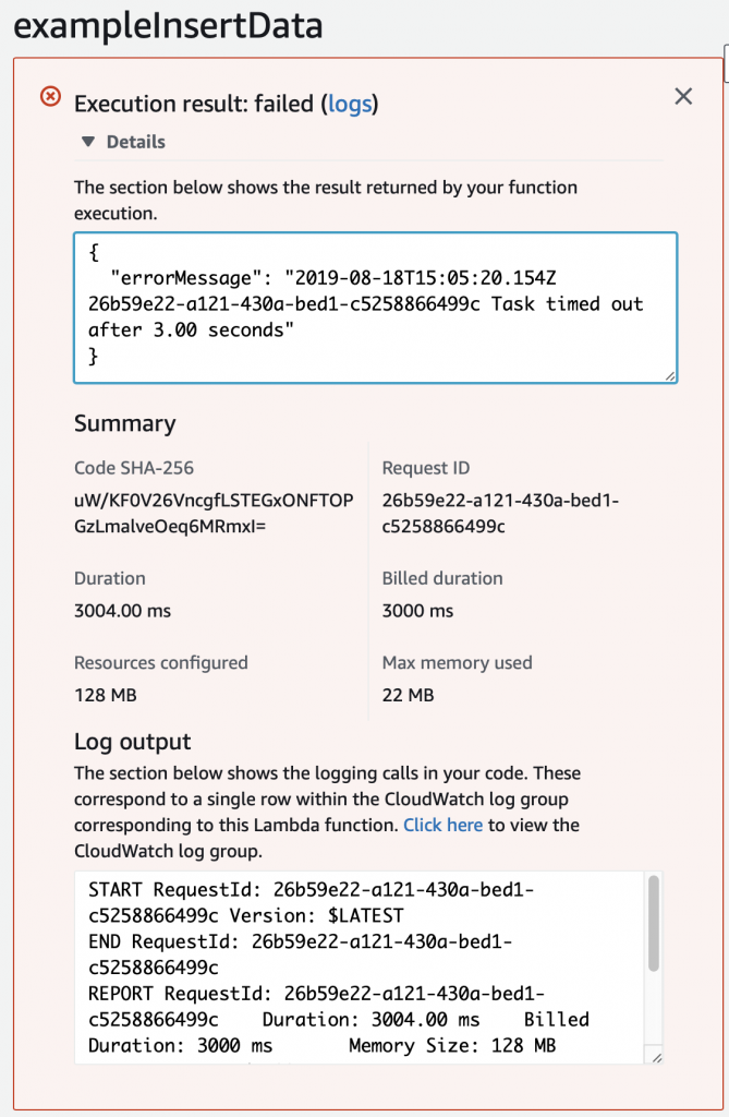
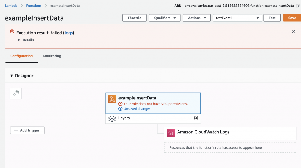
When I run the test, I get this message which took me a long time to figure out.  Like a stupidly long time.  In order to fix it, you need to configure the Lambda function to run in your VPC.

Configure the Lambda Function to Run in your VPC

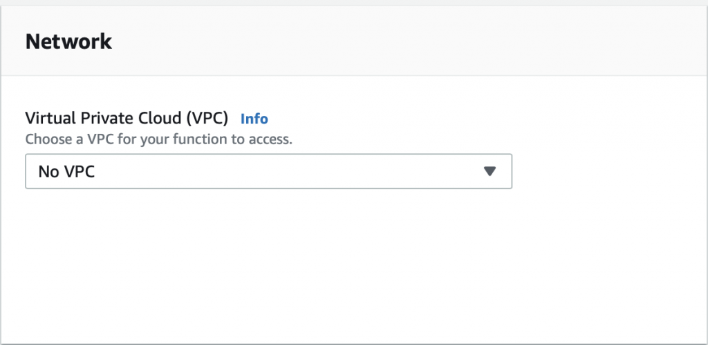
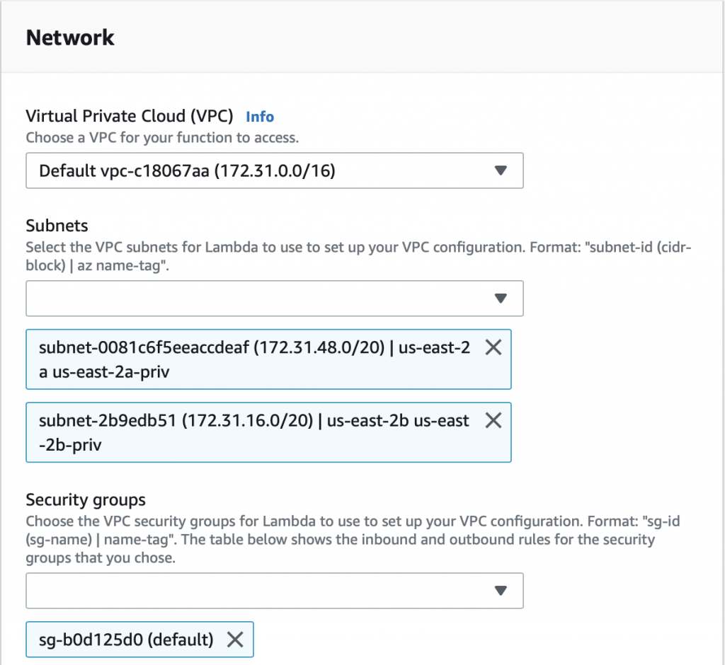
The problem is that the AWS Lambda Functions runs on the public Internet which does not have access to your AWS RDS database which you might recalls is on a private subnet in my VPC.  To fix this, you need to tell AWS to run your function INSIDE of your VPC.  Scroll down to the network section.  See where it says “No VPC”

Pick out your VPC and then pick out two subnets in your VPC.  You probably should pick two subnets from different availability zones.  But it doesn’t matter if they are public or not as they only talk to the database.

After clicking save I get this message “Your role does not have VPC permissions”.  This took forever to figure out as well.  To fix this problem, you need to create the correct IAM role….

Create an IAM Role and Assign to the Lambda Function

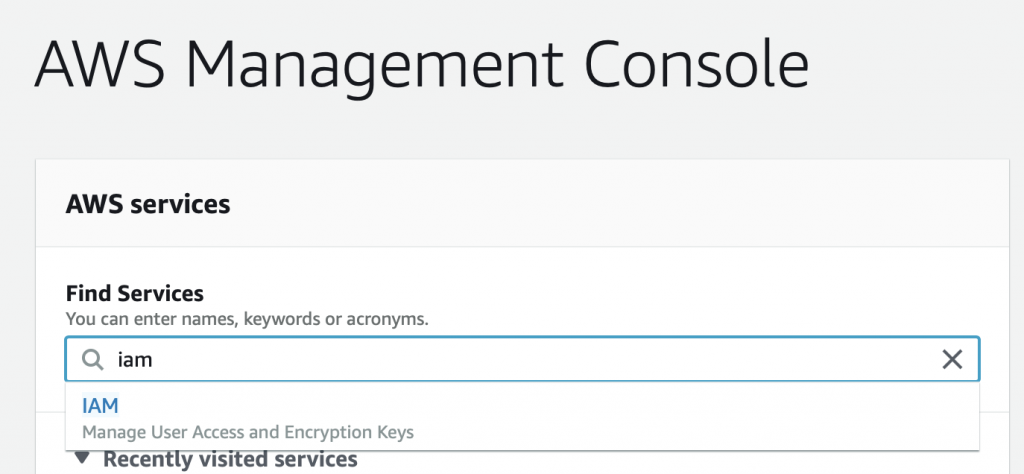
To create the role, you need to get to the IAM console and the “roles” sub console.  There are several way to get to the screen to create the role.  But I do this by going to the AWS console, searching for IAM, and clicking.

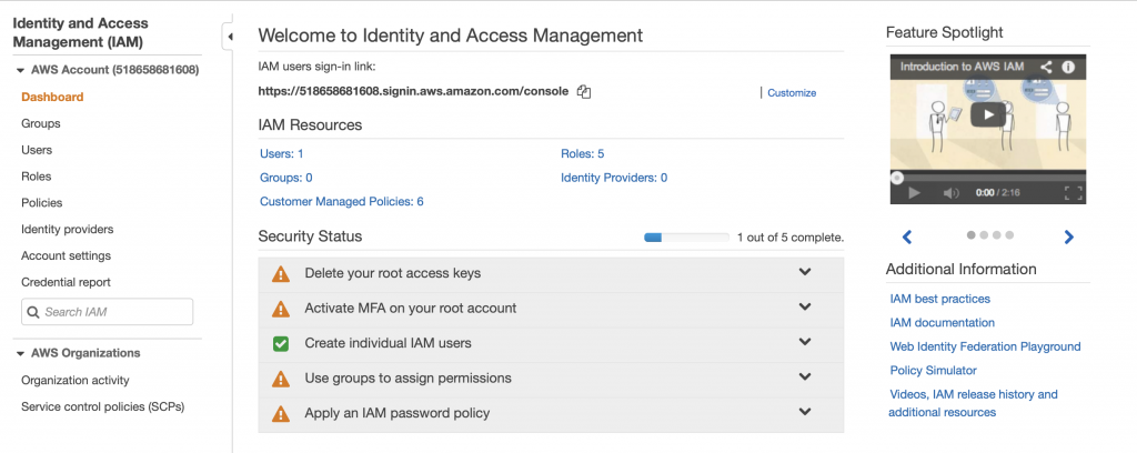
This takes me to the IAM Console.  I don’t know that much about these options.  Actually looking at this screen shot it looks like I have some “Security status” issues (which I will need to figure out).  However in order to get the Lambda function to attach to your VPC, you need to create a role.  Do this by clicking “Roles”

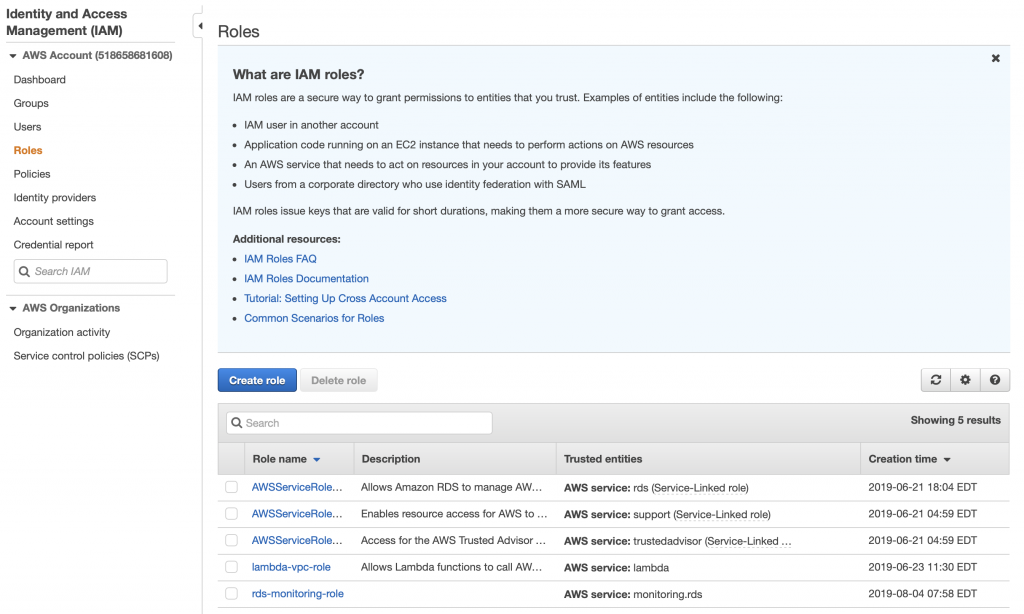
When you click on roles you can see that there are several roles, essentially rules that give your identity the ability to do things in the AWS cloud.  There are some that are created by default.  But in order for your Lambda function to attach to your VPC, you need to give it permission.  To do this click “Create role”

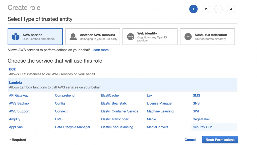
Pick “AWS service” and “Lambda” then click Next: Permissions

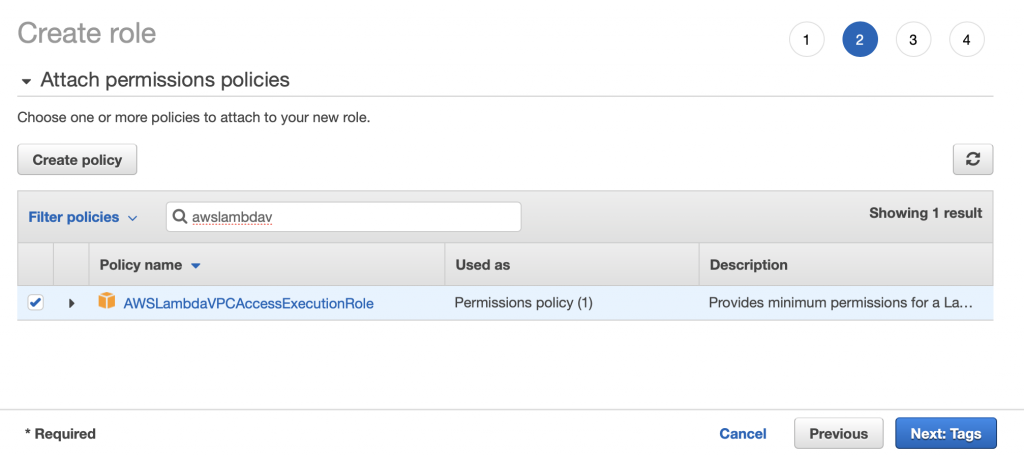
Search for the “AWSLambdaVPCAccessExecutionRole”.  Pick it and then click Next: Tags

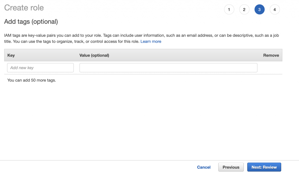
I don’t have any tags so click Next: Review

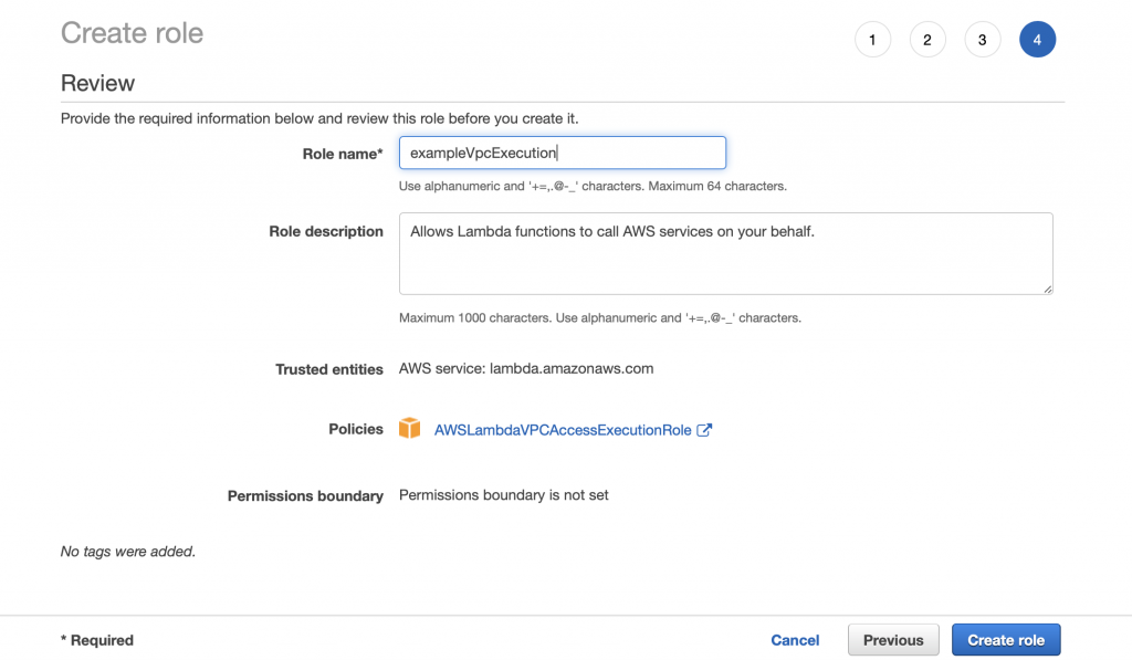
Give the role a name “exampleVpcExecution” then click Create role.

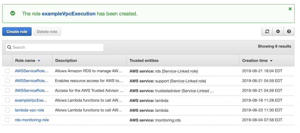
You should get a success message.

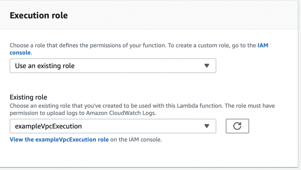
Now go back to the Lambda function configuration screen.  Move down to “Execution role” and pick out the role that you just created.

Now when I test things work…. now let’s fix up the function to actually do the work of inserting data.

Update the Lambda Function to Insert Data

You should recall from the article on AWS MQTT that when you update the IoT Device Shadow via MQTT you publish a JSON message like this to the topic “$aws/things/applecreek/shadow/update”

{
  "state": {
    "reported": {
      "temperature": 37.39998245239258,
      "depth": 0.036337487399578094,
      "thing": "applecreek"
    }
  }
}

Which will cause the AWS IoT to update you device shadow and then publish a message to “$aws/things/applecreek/shadow/update/accepted” like this:

{
  "state": {
    "reported": {
      "temperature": 37.39998245239258,
      "depth": 0.036337487399578094,
      "thing": "applecreek"
    }
  },
  "metadata": {
    "reported": {
      "temperature": {
        "timestamp": 1566144733
      },
      "depth": {
        "timestamp": 1566144733
      },
      "thing": {
        "timestamp": 1566144733
      }
    }
  },
  "version": 27323,
  "timestamp": 1566144733
}

In the next article Im going to show you how to hook up those messages to run Lambda function.  But, for now assume that the JSON that comes out of the “…/accepted” topic will be passed to your function as the “event”.

The program has the following sections:

  1. Setup the imports
  2. Define some Configuration Variables
  3. Make a logger
  4. Make a connection to the RDS database
  5. Find the name of the thing in the JSON message
  6. Search for the thingId in the table creekdata.things
  7. Find the state key/value
  8. Find the reported key/value
  9. Find the depth key/value
  10. Find the temperature key/value
  11. Find the timestamp key/value
  12. Convert the UTC timestamp to Eastern Time (I should have long ago designed this differently)
  13. Insert the new data point into the Database

Setup the Imports

The logging import is used to write data to the AWS logging console.

The pymysql is a library that knows how to attach to MySQL databases.

I made the decision years ago to store time in eastern standard time in my database.  That turns out to have been a bad decision and I should have used UTC.  Oh well.  To remedy this problem I use the “pytz” to convert between UTC (what AWS uses) and EST (what my system uses)

import sys
sys.path.append("./package")
import logging
import pymysql

from pytz import timezone, common_timezones
import pytz
from datetime import datetime

Define Some Configuration Variables

Rather than hardcode the Keys in the JSON message, I setup a number of global variables to hold their definition.

stateKey ="state"
reportedKey = "reported"
depthKey = "depth"
temperatureKey = "temperature"
timeKey = "time"
deviceKey = "thing"
timeStampKey = "timestamp"

Make a connection to the RDS Database

In order to write data to my RDS MySQL database I create a connection using “pymysql.connect”.  Notice that if this fails it will write into the cloud watch log.  If it succeeds then there will be a global variable called “conn” with the connection object.

rds_host  = "creekdata.cycvrc9tai6g.us-east-2.rds.amazonaws.com"
name = "database user"
password = "databasepassword"
db_name = "creekdata"

try:
    conn = pymysql.connect(rds_host, user=name, passwd=password, db=db_name, connect_timeout=5)
except:
    logger.error("ERROR: Unexpected error: Could not connect to MySQL instance.")
    sys.exit()
    

Make a logger

AWS gives you the ability to write to the AWS CloudWatch logging system.  In order to write there, you need to create a “logger”

logger = logging.getLogger()
logger.setLevel(logging.INFO)

Look for the stateKey and reportKey

The JSON message “should” have key called “state”.  The value of that key is another keymap with a value called “reported”

if stateKey in event:
        if reportedKey in event[stateKey]:

Find the Depth

Assuming that you have state/reported then you need to find the value of the depth

if depthKey in event[stateKey][reportedKey]:
                depthValue = event[stateKey][reportedKey][depthKey]

Find the Temperature

It was my intent to send the temperature every time I update the shadow state.  But I put in a provision for the temperature not being there and taking the value -99

if temperatureKey in event[stateKey][reportedKey]:
                temperatureValue = event[stateKey][reportedKey][temperatureKey]
            else:
                temperatureValue = -99

Look for a Timestamp

My current sensor system does not keep time, however, I may add that functionality at some point.  So, I put in the ability to have a timeStamp set by the sensor.  If there is no timestamp there, AWS happily makes one for you when you update the device shadow.  I look in

  • The reported state
  • The overall message
  • Or I barf
if timeStampKey in event[stateKey][reportedKey]:
                timeValue = datetime.fromtimestamp(event[stateKey][reportedKey][timeStampKey],tz=pytz.utc)
#                logger.info("Using state time")
            elif timeStampKey in event:
#                logger.info("using timestamp" + str(event[timeStampKey]))
                timeValue = datetime.fromtimestamp(event[timeStampKey],tz=pytz.utc)
            else:
                raise Exception("JSON Missing time date")

Find the name of the thing in the JSON message

My database has two tables.  The table called “creekdata” has columns of id, thingid, depth, temperature, created_at.  The thing id is key into another table called “things” which has the columns of thingid and name.  In other words, it has a map of a text name for things to a int value.  This lets me store multiple thing values in the same creekdata table… which turns out to be an overkill as I only have one sensor.

When I started working on this program I wanted the name of thing to be added automatically as part of the JSON message, but I couldn’t figure it out.  So, I added the thing name as a field which is put in by the sensor.

if deviceKey in event[stateKey][reportedKey]:
                deviceValue = event[stateKey][reportedKey][deviceKey]
            else:
                logger.error("JSON Event missing " + deviceKey)
                raise Exception("JSON Event missing " + deviceKey)

Search for the thingId in the table creekdata.things

I wrote a function which takes the name of a thing and returns the thingId.

def getThingId(deviceName):
    with conn.cursor() as cur:
        cur.execute("select thingid from creekdata.things where name=%s", deviceName)
    results = cur.fetchall()
#    logger.info("Row = " + str(len(results)))
    if len(results) > 0:
#        logger.info("thingid = "+ str(results[0][0]))
        return results[0][0]
    else:
        raise Exception("Device Name Not Found " + deviceName)

Convert the UTC timestamp to Eastern Time

As I pointed out earlier, I should have switched the whole system to store UTC.  But no.  So I use the pytz function to switch my UTC value to EST.

  tz1 = pytz.timezone('US/Eastern')
    xc = timeValue.astimezone(tz1)

Insert the New Data Point into the Database

Now we know everything, so insert it into the database.

with conn.cursor() as cur:
        cur.execute("INSERT into creekdata.creekdata (created_at,depth, thingid,temperature) values (%s,%s,%s,%s)",(xc.strftime("%Y-%m-%d %H:%M:%S"),depthValue,thingIdValue,temperatureValue));
    conn.commit()

The Final Program

Here is the whole program in one place.

import json
import sys
import logging
import os
sys.path.append("./package")
import pymysql
from pytz import timezone, common_timezones
import pytz
from datetime import datetime
stateKey ="state"
reportedKey = "reported"
depthKey = "depth"
temperatureKey = "temperature"
timeKey = "time"
deviceKey = "thing"
timeStampKey = "timestamp"
#rds settings
rds_host  = "put your endpoint here.us-east-2.rds.amazonaws.com"
name = "mysecretuser"
password = "mysecretpassword"
db_name = "creekdata"
logger = logging.getLogger()
logger.setLevel(logging.INFO)
try:
conn = pymysql.connect(rds_host, user=name, passwd=password, db=db_name, connect_timeout=5)
except:
logger.error("ERROR: Unexpected error: Could not connect to MySQL instance.")
sys.exit()
def lambda_handler(event,context):
logger.info('## EVENT')
logger.info(event)
insertVal = ""
if stateKey in event:
if reportedKey in event[stateKey]:
if depthKey in event[stateKey][reportedKey]:
depthValue = event[stateKey][reportedKey][depthKey]
if temperatureKey in event[stateKey][reportedKey]:
temperatureValue = event[stateKey][reportedKey][temperatureKey]
else:
temperatureValue = -99
if timeStampKey in event[stateKey][reportedKey]:
timeValue = datetime.fromtimestamp(event[stateKey][reportedKey][timeStampKey],tz=pytz.utc)
#                logger.info("Using state time")
elif timeStampKey in event:
#                logger.info("using timestamp" + str(event[timeStampKey]))
timeValue = datetime.fromtimestamp(event[timeStampKey],tz=pytz.utc)
else:
raise Exception("JSON Missing time date")
if deviceKey in event[stateKey][reportedKey]:
deviceValue = event[stateKey][reportedKey][deviceKey]
else:
logger.error("JSON Event missing " + deviceKey)
raise Exception("JSON Event missing " + deviceKey)
else:
raise Exception("JSON Event missing " + reportedKey)
else:
raise Exception("JSON Event missing " + stateKey)
thingIdValue = getThingId(deviceValue)
tz1 = pytz.timezone('US/Eastern')
xc = timeValue.astimezone(tz1)
with conn.cursor() as cur:
cur.execute("INSERT into creekdata.creekdata (created_at,depth, thingid,temperature) values (%s,%s,%s,%s)",(xc.strftime("%Y-%m-%d %H:%M:%S"),depthValue,thingIdValue,temperatureValue));
conn.commit()
return "return value"  # Echo back the first key value
def getThingId(deviceName):
with conn.cursor() as cur:
cur.execute("select thingid from creekdata.things where name=%s", deviceName)
results = cur.fetchall()
#    logger.info("Row = " + str(len(results)))
if len(results) > 0:
#        logger.info("thingid = "+ str(results[0][0]))
return results[0][0]
else:
raise Exception("Device Name Not Found " + deviceName)

The Creek 2.0: AWS Relational Database Server (RDS) – MySQL

Summary

In the previous articles I showed you the overall Creek 2.0 Architecture (1-8).  Then I explained how AWS MQTT (5) works, and I showed you how to write a Python program to update the device shadow (4).  In this article, I will create an AWS Relational Database Server (RDS) that runs MySQL which will be used to store the data.

You might ask yourself why would I explain (8) before I explained (6) & (7)?  The answer is that I need a place to send the data before the send the data functions will make any sense.

First, a definition, RDS – Relational Database Server – is Amazons name for a service that give you a database server, in your VPC, running an instance of MySQL, Aurora, DynamoDb, or Postgres.  In their words, RDS “…provides cost-efficient and resizable capacity while automating time-consuming administration tasks such as hardware provisioning, database setup, patching and backups.”   The AWS definition is largely true.  It does not however abdicate your DataBase Administrator (DBA) responsibilities.

For my application I need MySQL, so for this article I will walk you through setting up a MySQL database using AWS RDS.  The specific topics are:

  1. Create a Database Using the Amazon Defaults
  2. Create MySQL WorkBench Connection
  3. Examining the Security
  4. Rethinking the Security & Subnet Groups
  5. Configure Security Groups
  6. Create the Database I Really Want
  7. MySQL WorkBench EC2 Tunneling over SSL

Create a Database Using the Amazon Defaults

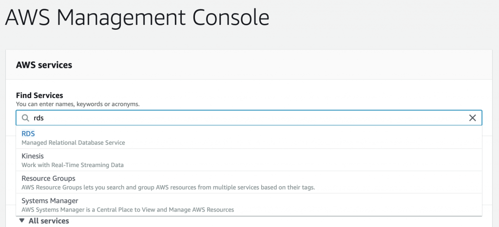
It is really easy to create a MySQL database using the default Amazon settings.  The setting will be absolutely fine, except that the Database will be attached to a Public Subnet rather than a private one.   This is probably mostly OK as the subnet settings that AWS creates by default are probably safe enough?  It is certainly easy, so let’s start there.  Go to your AWS management console.  Then search for RDS.

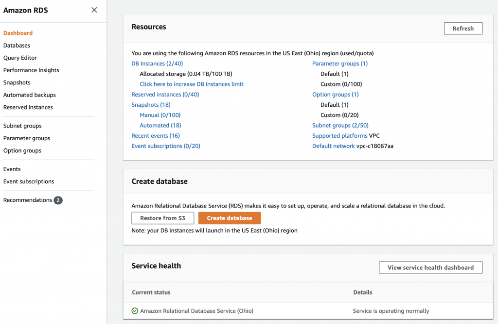
You will arrive a screen that should look something like this one.  I say should because 1) they like to change things around and 2) I already have some stuff going in my RDS setup. To create a database click  on “Create database”


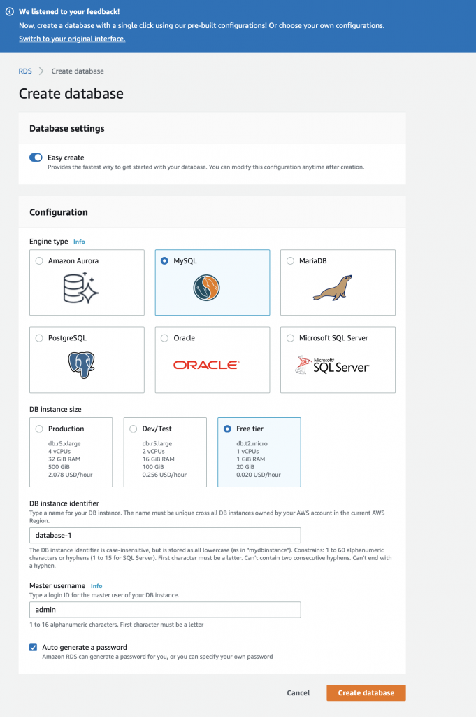
When you get to the create database screen it will give you some options.  Notice at the top of my screen shot they are already offering me a new user interface.  For the first database select:

  • Easy Create
  • MySQL
  • Free Tier
  • DB instance identifier (I leave the default database-1)
  • Master username = admin
  • Autogenerate password

Then press “Create database”

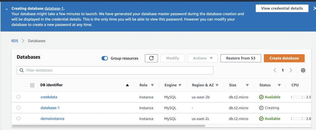
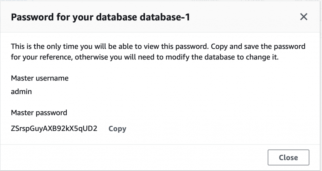
Creating a database takes about 5 minutes.  In the screen shot below you can see that it is “Creating” and that I am already running two other databases.  Also you can see at the top of the screen it says “View credential details”.  This is where you find out the password that was automatically created for you.  If you leave this screen without the password your database becomes inaccessible and you will need to delete it.

When you click the details screen you will get something like this:

Once the database is created your screen will look something like this:

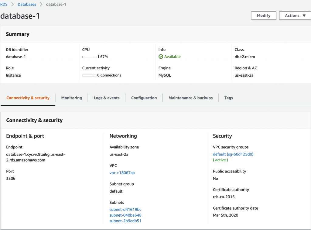
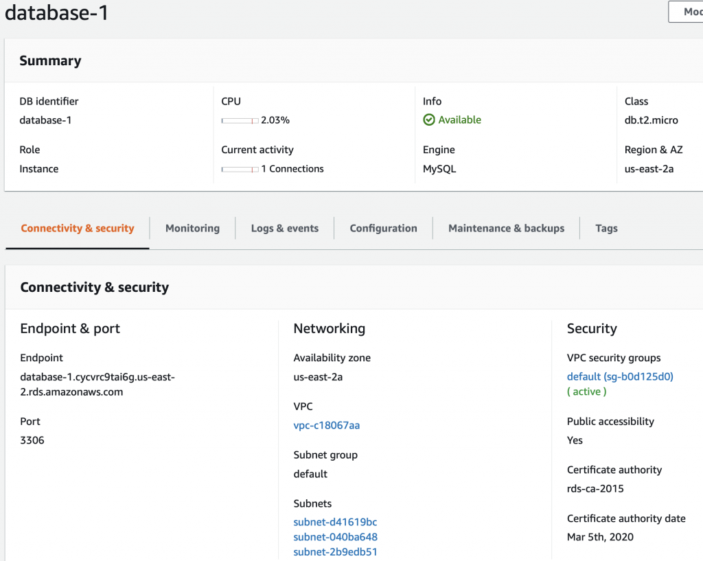
When you click on database-1 (the one we just created) it will show you details about the database.  This screen has a bunch of useful information including the endpoint a.k.a the DNS name of your database.

Create MySQL WorkBench Connection

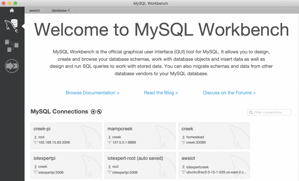
I am not a real database administrator so I like to use the MySQL Workbench GUI to access my database.  To make a new connection, press the little plus next to MySQL Connections.

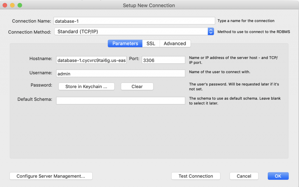
On this screen you need to provide the hostname, which in Amazon terms is the endpoint.  You also need to give the Username (which in my case was default admin) and the crazy generated password.

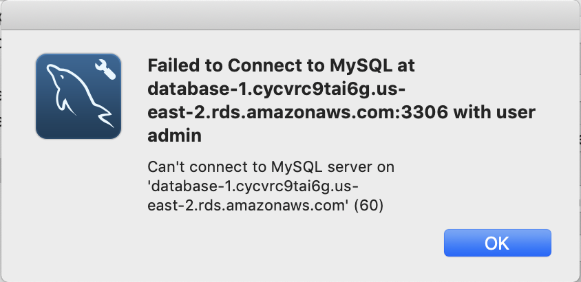
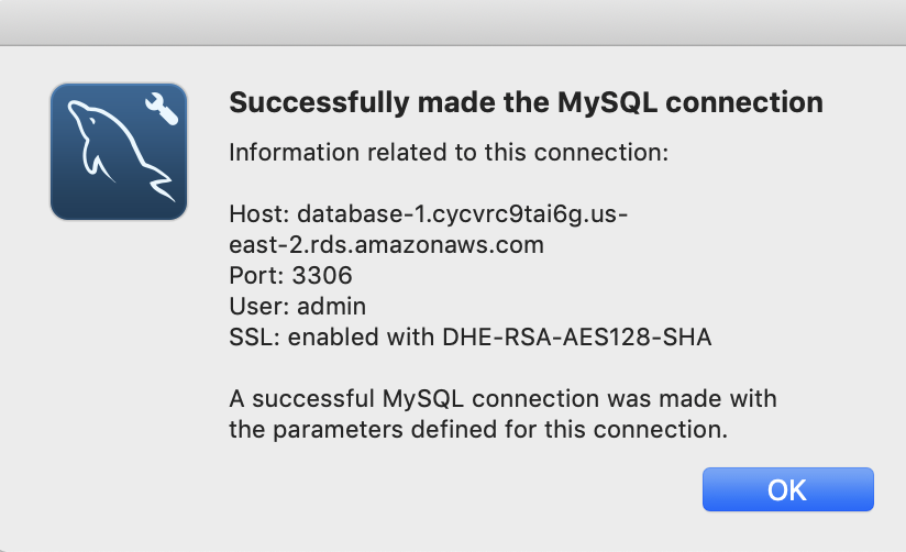
When I press the “Test Connection” I get this lovely message.

The problem is that my database is not “Publicly available”  To fix this click on “Modify”

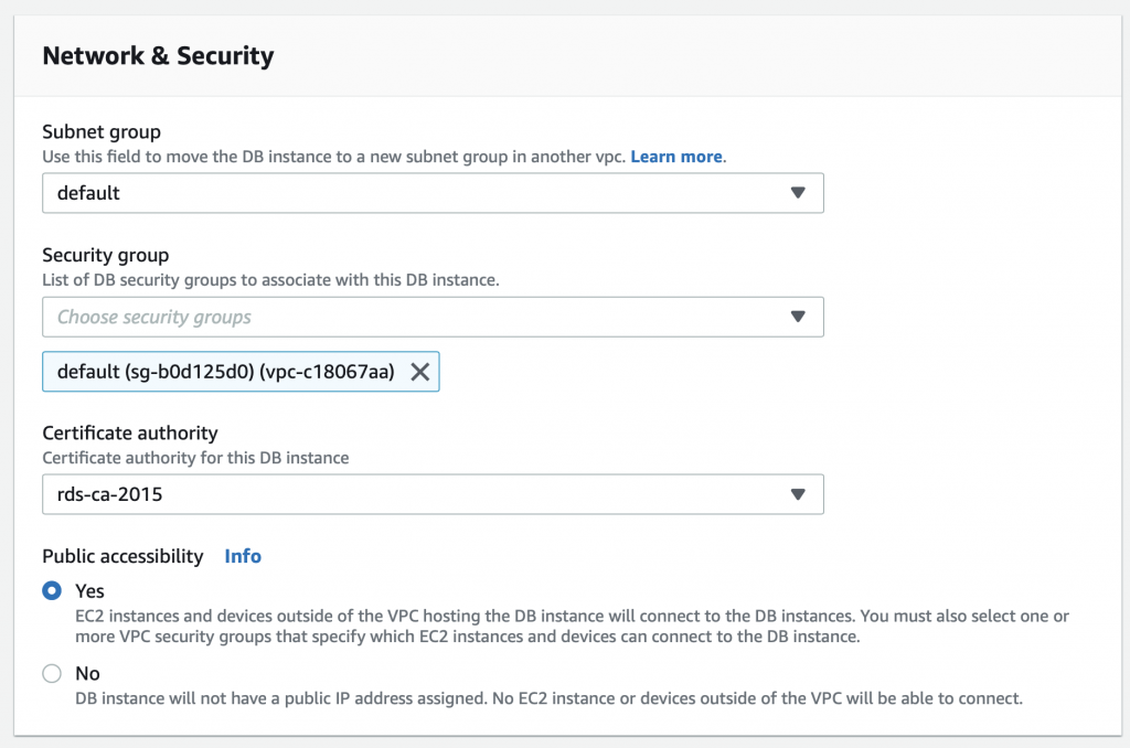
Then scroll down to “Network and Security” and select “Public accessibility” and pick yes.

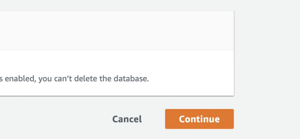
Then scroll down some more and pick “Continue”

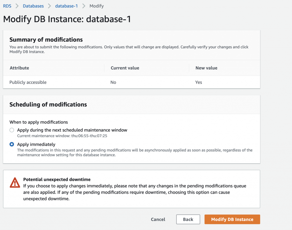
It will then ask you when?  Tell it NOW!!! right NOW!!! I can’t WAIT!!!  But seriously, it doesn’t matter because we don’t have anything in the database and no connections.

On my database this takes about a  minute… so be patient. I wasn’t and the connection didn’t work and I went looking to figure out why.  I finally realized that it was because it took a while to make the change.  Now when I test the connection it says:

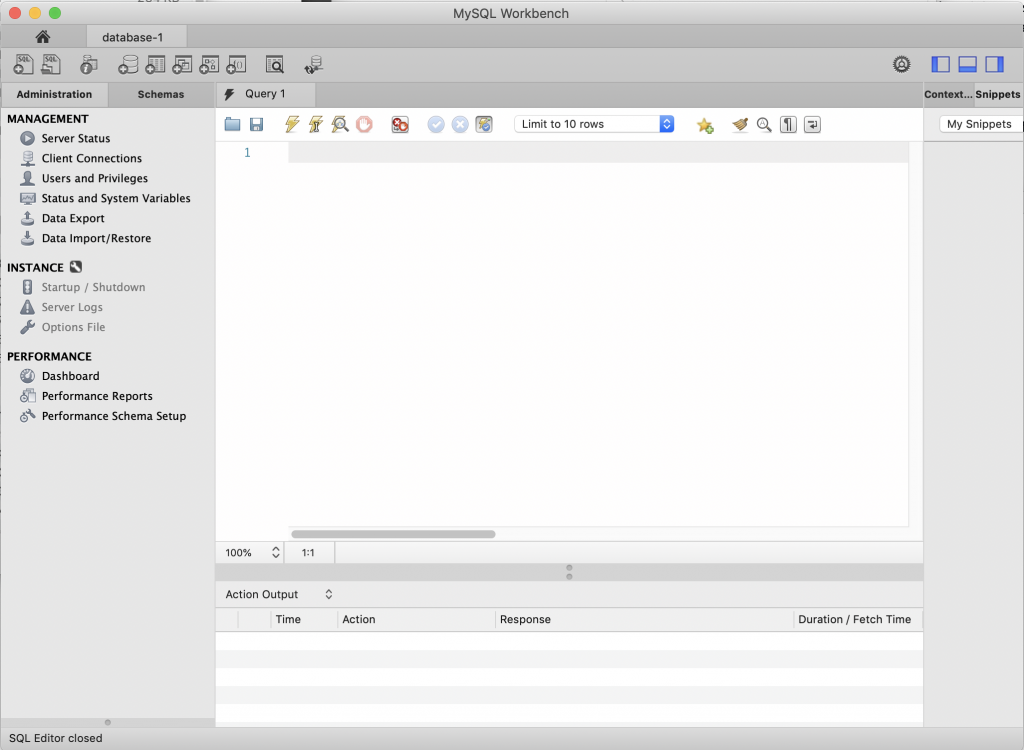
And when I open the connection it works.

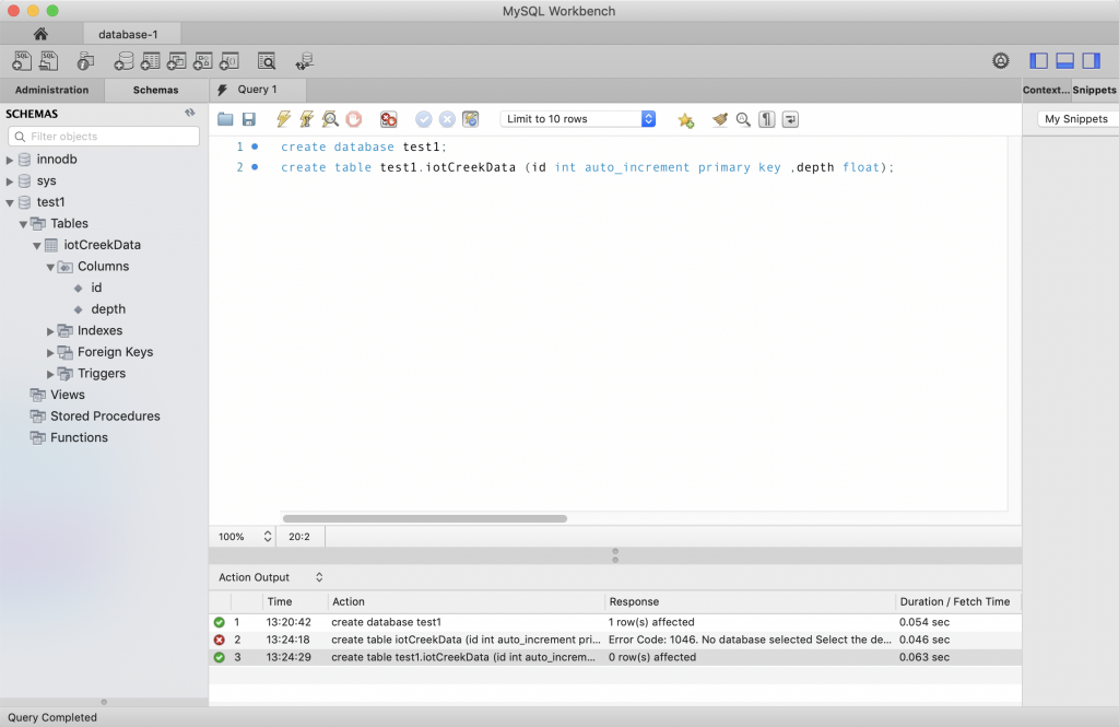
Now I can make database and a table.

Examining the Security

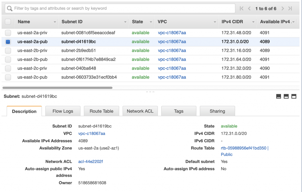
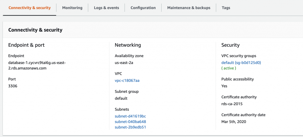
A couple of things to notice about this database.  First, this database is setup to run on us-east-2a.  And that the database is in the “Default” subnet group which is either subnet-d41619bc, subnet-040ba648 or subnet-2b9edb51 (three subnets in the three availability zones in us-east-2).  For some reason which I can’t figure, they don’t display which subnet instead they make you figure it out by combining region and you knowledge of the subnets.

But wait is that subnet public or private?  And which one is it?  If you go to the AWS console for the VPCs and then click on the subnet tab you will find this configuration (at least in my VPC).  I did this work for the article I did on VPCs where I setup one private and one public subnet for each of the availability zone in the us-east-2.  From the screen above you can see that my RDS is setup in us-east-2a which means that it is on subnet-d41619bc.

Notice that I gave that network the name us-east-2a-pub because it is a PUBLIC network.  Which you can see when you click on it.  Notice that the Route Table is Public.

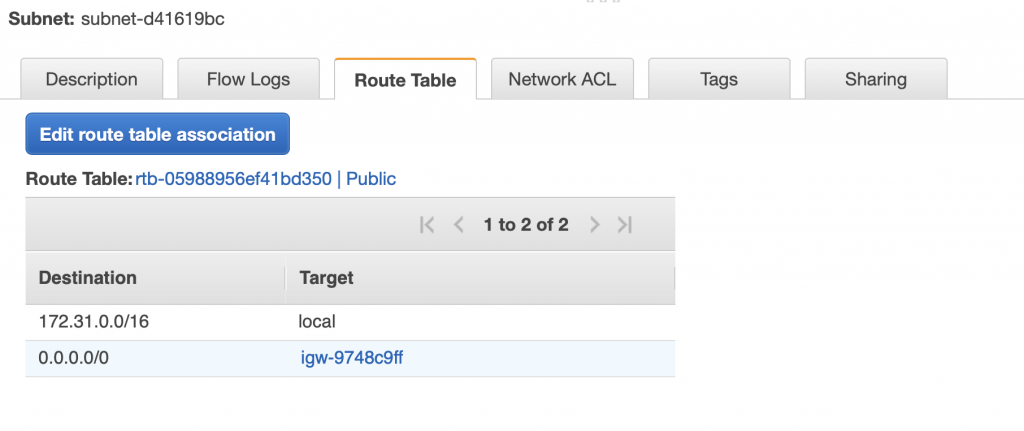
When you click on “Route Table” you see that it has 0.0.0.0/0 sent to the Internet gateway named igw-9748c9ff

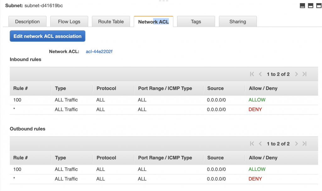
And that the Network ACL allows all traffic to and from the subnet.

Rethinking the Security & Subnet Groups

Having a MySQL database server directly connected to the public internet may not actually be such a good idea.  Whatever application you develop for sure wants to be able to connect to it, but do you really want the rest of the world hacking at it?  Probably not.  If the database server is attached to a private subnet that only servers that are inside of your VPC are allowed to attach to it.

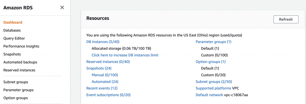
How do you move a RDS from a public to a private subnet?  Well, unfortunately, there is no good way to do that (there is a way but just not very good) and you actually needed to get it into the correct subnet when you created the database.  But you might ask yourself, there was no place on any of those screens to setup the subnet.  And that is true.  BUT you can tell it which “subnet group” to attach to.  A subnet group is literally just a list of subnets with a name.  On the RDS console on the far right there is a link to subnet groups.  In my class the link says “Subnet Groups (2/50)”.  It sure seems like this tab should be on the VPC screen and I can’t think of any reason they wouldn’t have put it there.  But there it is.  When you click on the “Subnet Groups…”

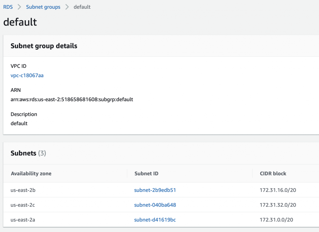
You see that there are two subnet groups.  One called “default” and one called “test1” (which I created while I was making all of these screen shots).  If you click on default …

You will see that this group contains 3 subnets.  In fact this group was created automatically for you and contains ALL of the subnets in your VPC that were automatically created for you when the VPC was created.  Since that time I made some of them private which is the source of confusion.

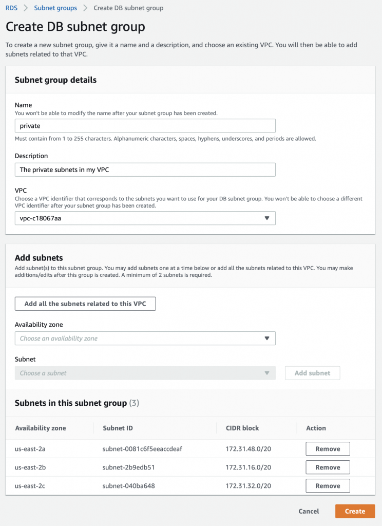
In order to create a new subnet group you click on the button “Create DB Subnet Group”

Then set things up:

  • Named the group “private”
  • Made a short description
  • Clicked “Add all of the subnets in the group”
  • Then I removed the public ones.
  • Then press create

Alternatively, you could just add the private ones by selecting the availability zone, then the private subnets.

Configure Security Groups

The next thing that is goofy in security is that when I click on the VPC security groups I can see the security configuration for that subnet.

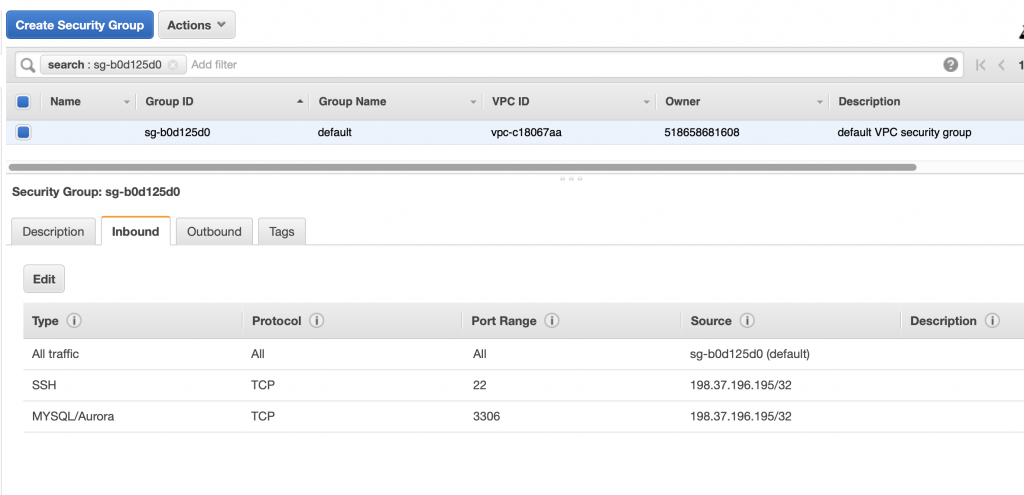
When I click on that security group you can see that the Amazon helped me by adding an Inbound rule to the security group to allow connections from 198.37.196.195 (which is the current IP address at my house) on port 3306.  In other words it poked a hole in the firewall that was limited to MySQL connections from my house… which I suppose is cool until my DHCP address changes.  Oh well.

Create the Database I Really Want

OK lets create the database that we really want.  First, I will delete the database that I don’t want because there is not really any way to move it to another subnet.  Well, that actually isn’t true.  Apparently you can create a new VPC, transfer the RDS to the new VPC, then transfer it back to the original VPC, then delete the temporary VPC.  But that isn’t what I’m doing.

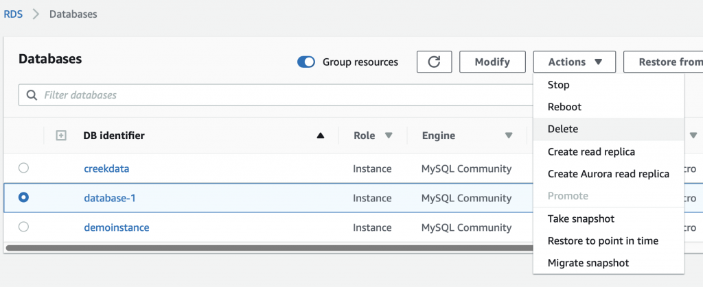
If you select the database, then select actions->delete.

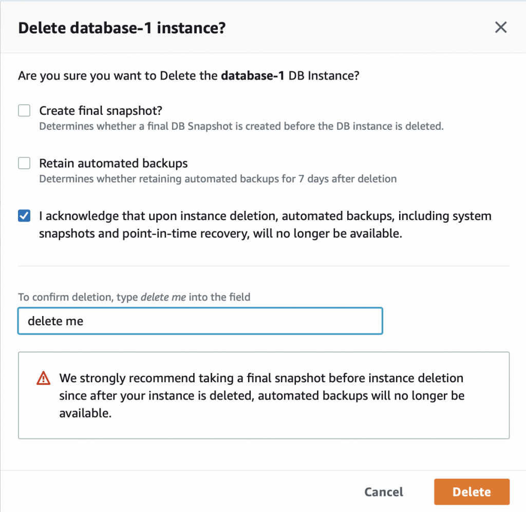
It will ask you if you are SURE!!! Because there is no data in the database I turn off the final snapshot.  I acknowledge that Im really sure… and then press “delete me”

Then it takes a bit of time to delete.

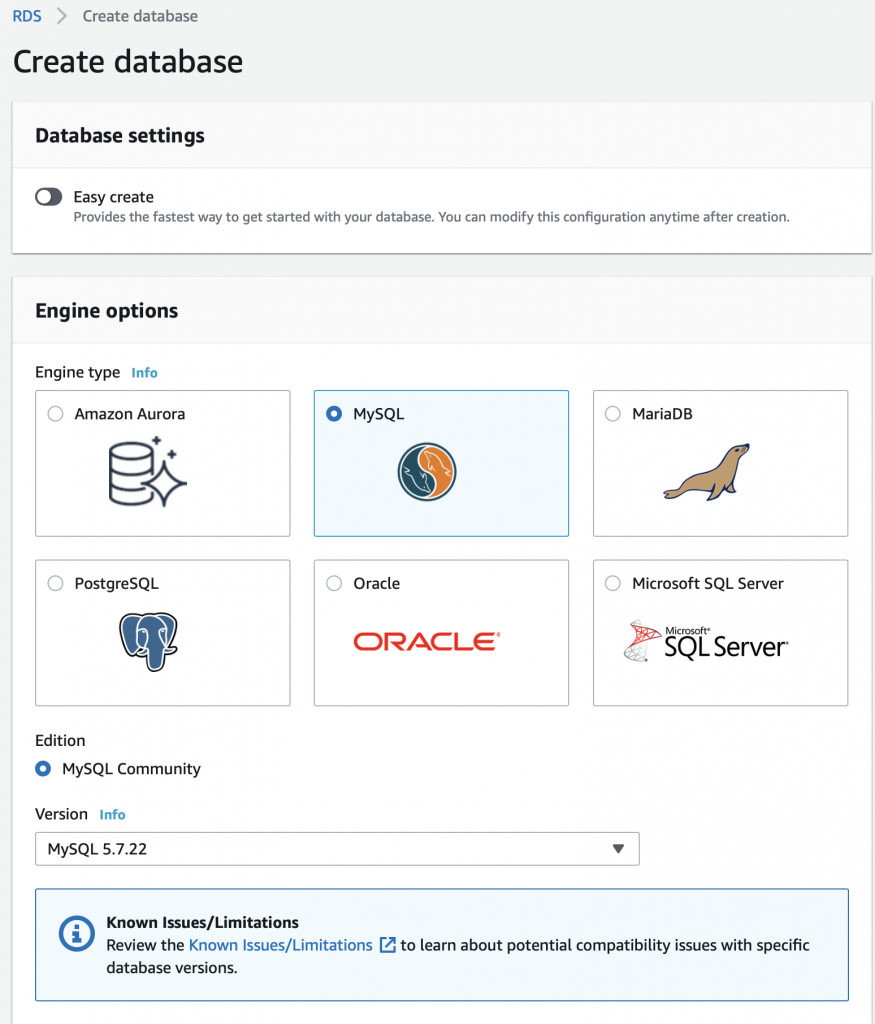
Now I press Create database. Turn off easy create (so that I get access to the option to place the the new database in the correct subnet group.

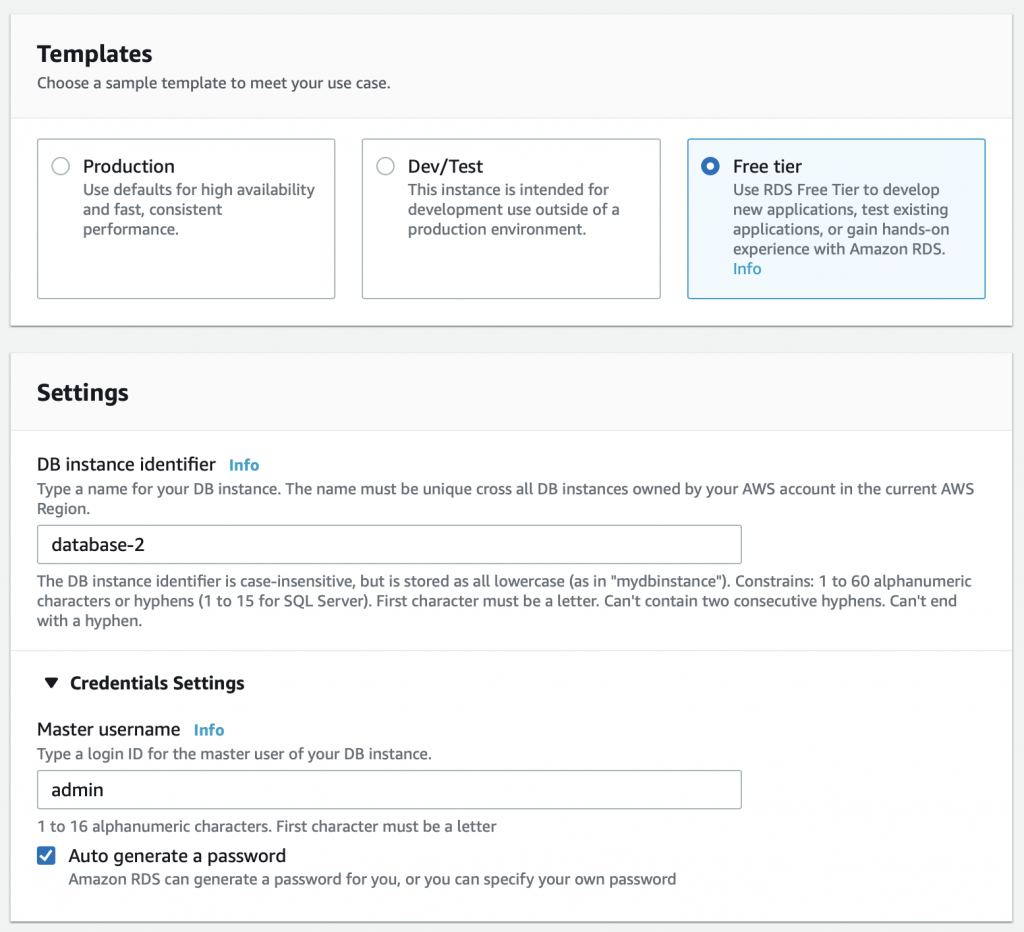
Free tier is plenty good for this setup.  And I don’t really care what the name of the database is.  As before I’ll let it generate the password.

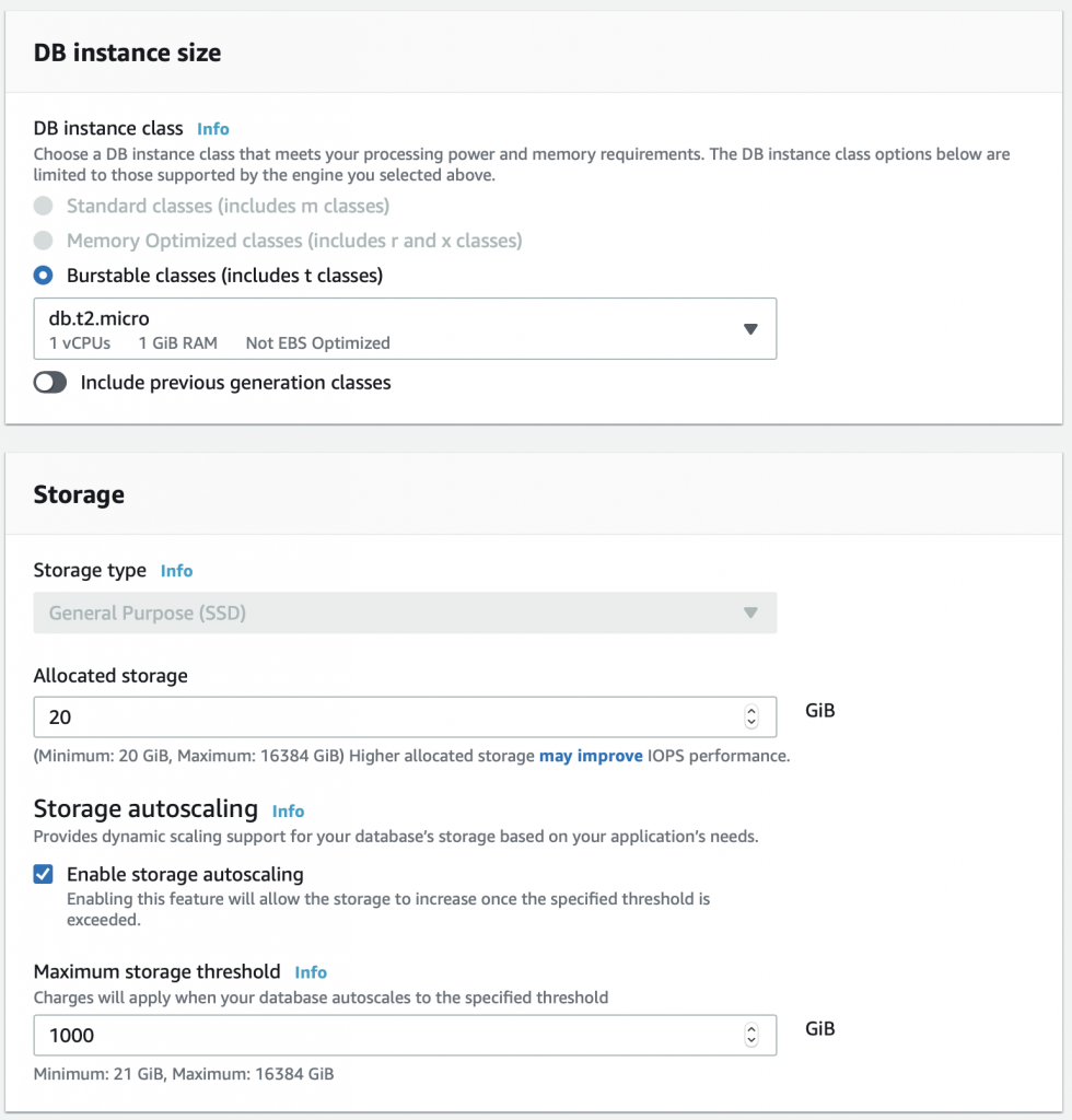
No choices on the instance size.

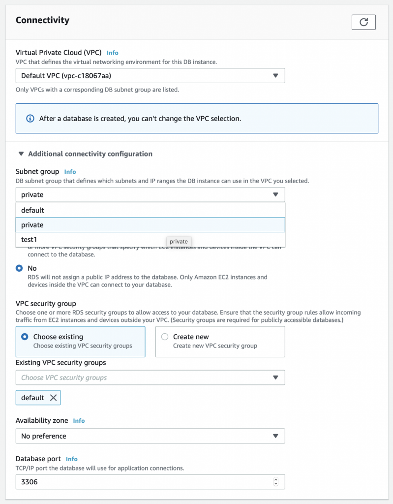
Finally in the connectivity section there is something interesting.  You need to expand the “additional connectivity configuration” to see these options.  Specifically, I can pick out the subnet group for this RDS instance.  Recall from above I created the private subnet group.  Pick it.

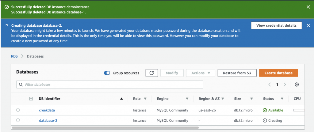
When I press create, I get this screen … sweet success.

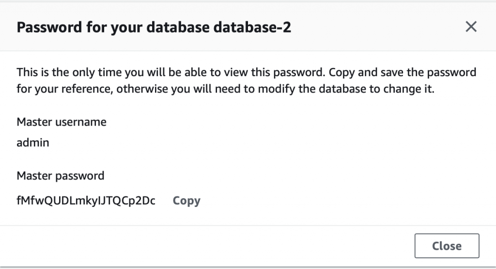
And once again it creates credentials for me.

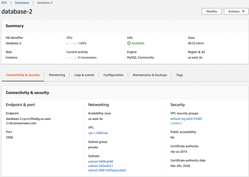
Now I have “database-2” which is running in “us-east-2a”

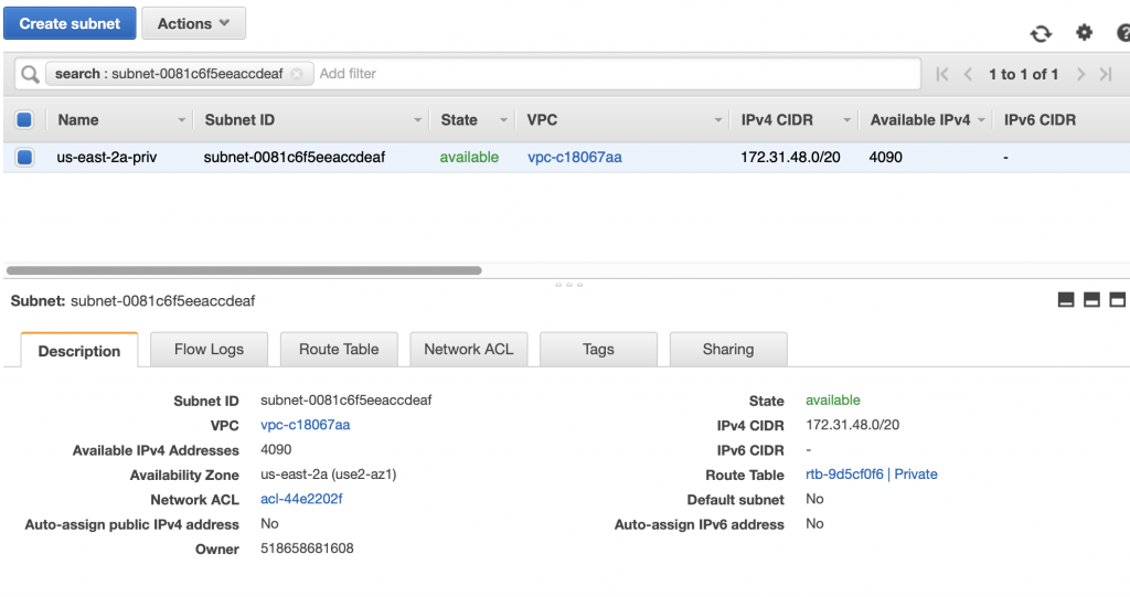
Click on database-2 and you can see that it is in the “private” subnet group.  If you look higher in this article you will find out that it MUST be running on subnet-0081c6f5eeaccdeaf.

When I click on that subnet I find that it is a private subnet in us-east-2a.  Notice that the route table is marked as “Private”

MySQL WorkBench EC2 Tunneling over SSL

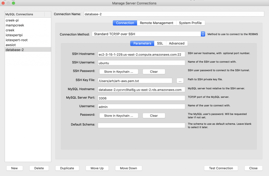
All that security is cool and everything.  But, How do I talk to the database?  Well, the answer to that question is that the RDS server is running in my VPC and any computer that is attached to that VPC can talk to the database server.   To make all of this work, I run an EC2 server in my VPC.  You can only attach to this server if you have the RSA keys.  But that still doesn’t answer the question how do I connect from my computer.   The answer is you need to do MySQL Tunneling over SSL.  To set this up in MySQL Workbench, first create a new connection.

  • Pick the connection method as “Standard TCP/IP over SSH”
  • Set the SSH Hostname to be your EC2 Instance
  • Set the User (I have the default ubuntu)
  • Make a link to your keyfile
  • Give the DNS name of your RDS Server
  • The user name (remember from above it is admin)

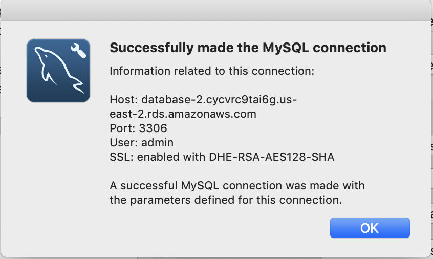
Now when I test the connection… sweet success.

And now I can talk to the MySQL server (and do whatever SQL stuff I want)

In the next article I will create a lambda function to send data onto the RDS database.

Debugging SSD1306 Display Problems

Summary

This article explains in detail how to use and debug SSD1306 displays.  In this article, I use the Segger emWin library and MBEDOS, but for all practical purposes this discussion applies to all other interfaces to the board including Arduino, Raspberry Pi, Adafruit, etc.  I will say from the outset that I spent far far too much time digging into the inner workings of an 11 year old graphics driver.  Oh well, hopefully someone will get some benefit.

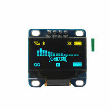
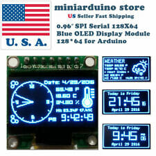
A year ago (or so) I designed a user interface board called the CY8CKIT-032 to go with my Cypress WICED WiFi book and class.  This board uses a PSoC 4 Analog co-processor which can do a bunch of cool stuff.  I have a series of articles planned about that board, but that will be for another day.  One of the things that I did was put a 0.96″ I2C OLED Display based on a SSD1306 driver on the board.  These displays are widely available from Alibaba and eBay for <$2.  I think that the displays are being used in inexpensive cells phones in China so there are tons of them and they are CHEAP!  The bad news is that if you google “ssd1306 problems” you will find an absolute rogues gallery of unpleasantness.  It seems that tons of people struggle to get these things working.
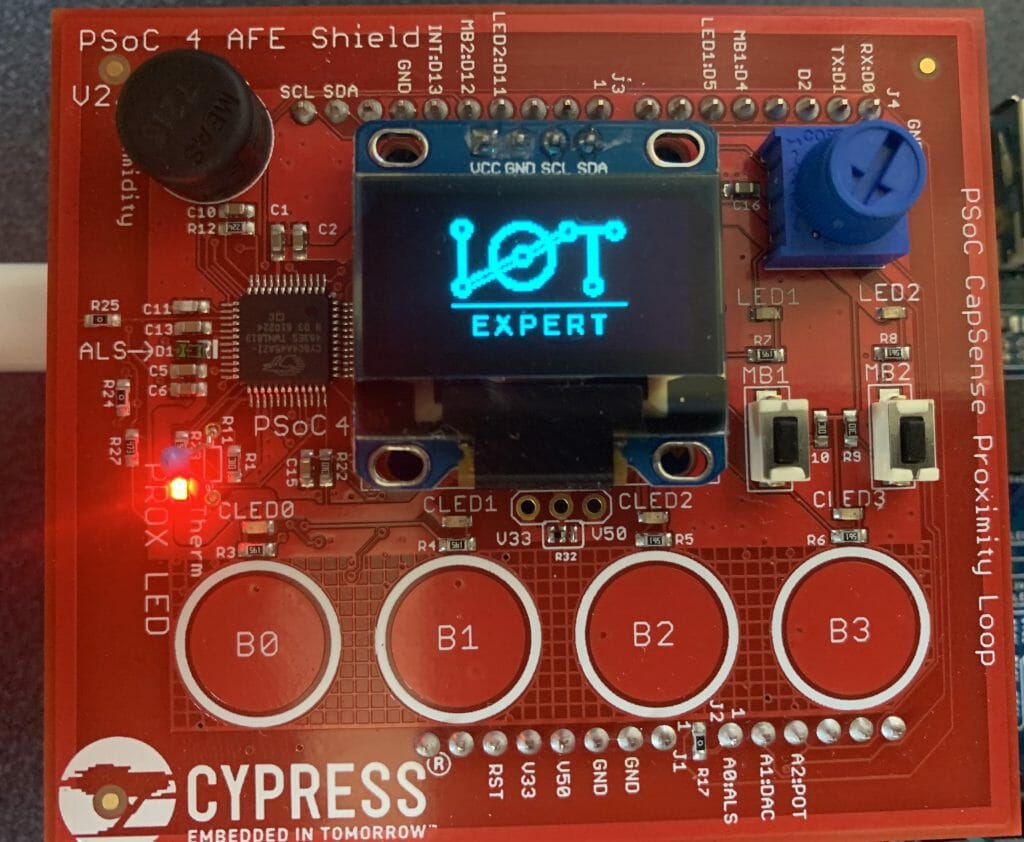
This whole thing started last week as Cypress released and update to our MBED OS implementation.  This update included releasing a complete set of the Segger emWin drivers.  I had been wanting to step up to a more robust graphics library than the Adafruit library that I used in this article.  I was pleased to see that our release included the emWin SPAGE driver which knows how to talk to a bunch of different page based displays including the SSD1306.

But, as always, I had to wrestle with the display a little bit before I got everything working.  This time I wrote down what I did/learned.  So, for this article I will describe

  • The SSD1306 Electrical Interface
  • The SSD1306 Software Interface
  • The SSD1306 Driver Registers
  • The SSD1306 Graphics Data RAM
  • Reading from the Frame Buffer
  • My Initialization Sequence
  • Some Other Initialization Sequences
  • A Bunch of Screen Problems & How To Fix

The Electrical Interface

There is not a lot to know about the electrical interface.  The data sheet specifies that the device can use I2C, SPI, 6800 and 8080.  I have not seen either the 6800 or 8080 interface put onto any of these OLED displays.  Like all driver chips, the SSD1306 has an absolute boatload of pins, in fact, 281.  The chip is long and skinny and was made to be mounted either on the display under the glass or on the flex connector.  Of the 281 pins, 128+64=196 are connected to the segments and commons in the display.  The rest of the pins are either capacitors, no-connects, power/ground or data signals.  The data signals are

  • D0-D7 either parallel data for 8080/6800 or SDA/SCL for I2C or MOSI/MISO for SPI
  • E – enable signal for 6800 or RD for 8080
  • R/W# – Read Write for 6800/8080
  • CS – Chip Select for SPI, 8080, 6800
  • D/C# – Data or Command for SPI, 6800, 8080 or Slave Address Select for I2C
  • Reset – Chip reset

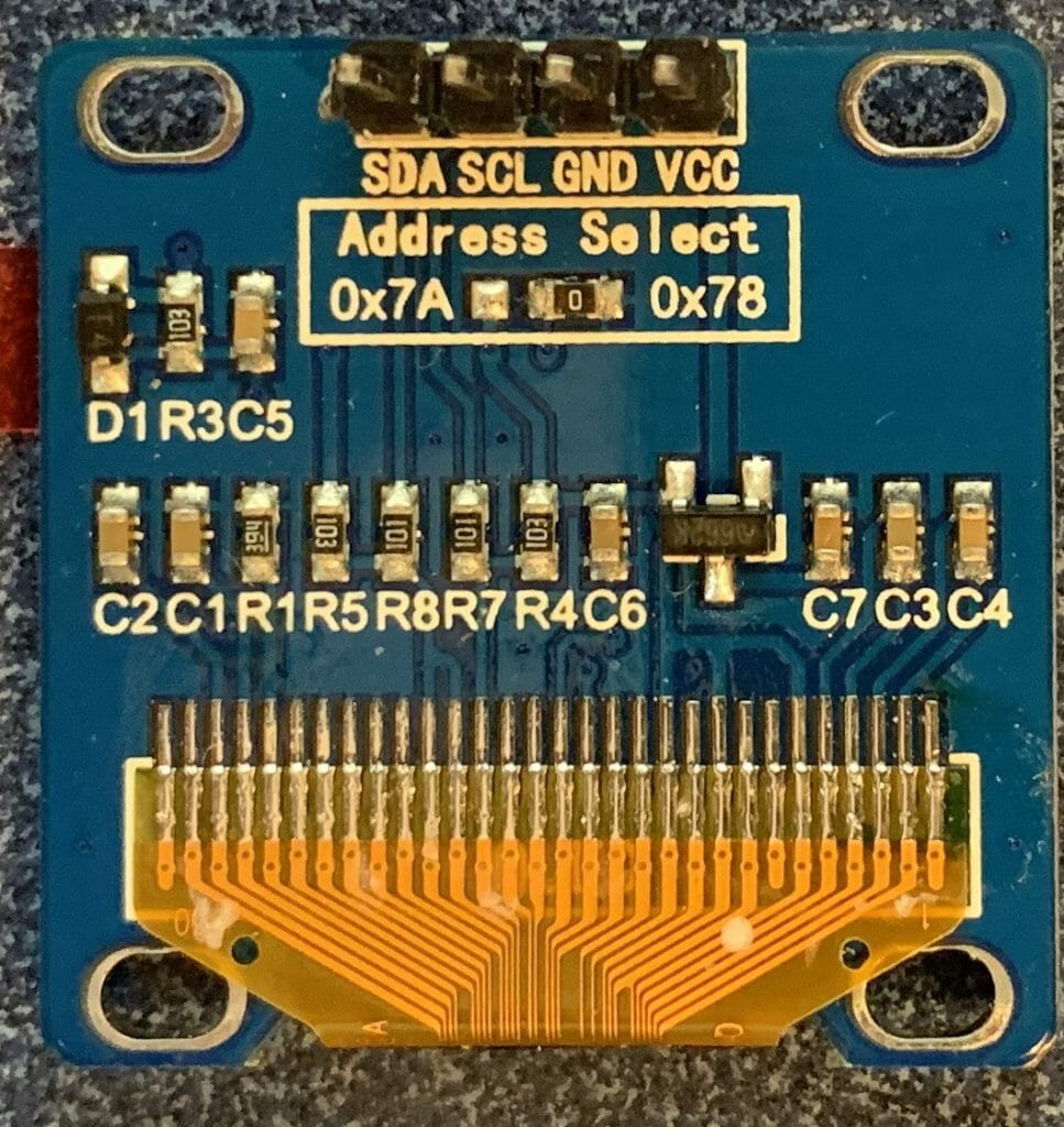
For the I2C configurations it is common to tie the reset pin High and not bring the pin to a connector.  The SA0 is also typically connected via a 0-ohm resistor to either 0 or 1 which configures the device to have the 7-bit address 0x3C or 0x3D or 8-bit 0x78 or 0x7A.  Here is a picture of the back of one of my boards where you can see the 0ohm resistor.
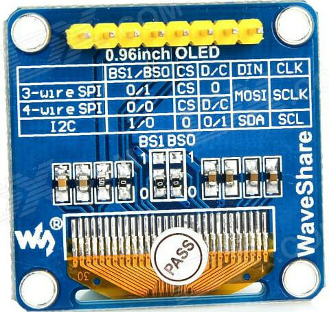
Sometimes all of the data pins are available on the back of the board.  This lets you move/add/change the 0-ohm resistors to configure the mode of the chip.
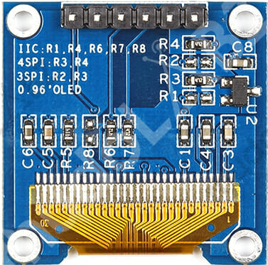
One thing you should be careful about is the I2C connections.  I looked around on eBay and Alibaba to find a few pictures of the I2C displays.  You should notice that all three of these displays are I2C, but all three of them have a different position and ORDER of VCC/GND/SCL/SDL  When we ordered displays from China to go onto the CY8CKIT-032 we found displays in the same BATCH that had different orders of the VCC/GND.
   

Here is a SPI version that has reset and data/command pin brought out.


The Software Interface

There are two parts to the software interface.

The first part is the command interface.  Inside of the chip there are a bunch of logic circuits which which configure the charge pumps, sequence COMs and SEGs, charge and discharge capacitors etc.  All of these things are configurable to allow for different configurations of screens e.g. different x-y sizes, configuration of what wires are connected to what places on the glass etc.  Before you can get the display to work correctly you must initialize all of these values by sending commands.  All the commands are 1-byte followed by 0 or more command parameters.

The second part is the data interface.  Inside of the SSD1306 chip there is a Graphics Display DRAM – GDDRAM which has 1 bit for every pixel on the screen. The state machine inside of the chip called the Display Controller will loop through the bits one by one and display them on the correct place on the screen.  This means that your MCU does not need to do anything to keep the display up to date.  When you want a pixel lit up on the screen you just need to write the correct location in the GDDRAM.
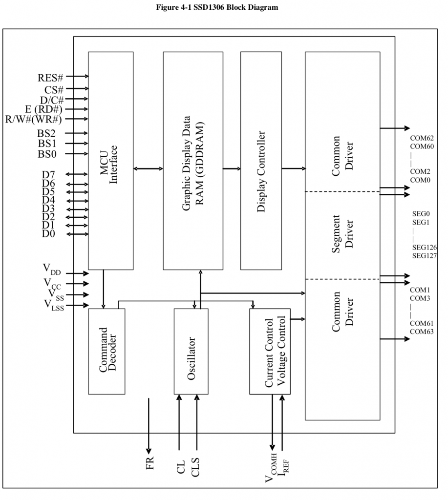
For the rest of this article I will focus on the serial interface, I2C.  How do you send commands and data?  Simple.  When you start a transaction you send a control byte which tells the controller what to expect next.  There are four legal control bytes.

  • 0b10000000 = 0x80 = multiple commands
  • 0b00000000 = 0x00 = one command
  • 0b11000000 = 0xC0 = multiple data
  • 0b01000000 = 0x40 = one data byte

Here is the picture from the datasheet (which I don’t find particularly illuminating) but it does describe the control byte.
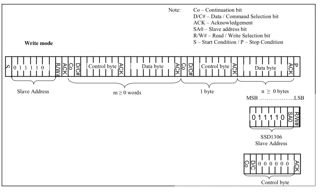
To send commands you write to the I2C bus with a control byte, then you send the command, then you send the optional parameters.  If you want to send multiple commands you send the control byte 0x80, the command + parameters as many as you need.

The SSD1306 Driver Registers

In order for the driver chip to drive the screen you need to configure:

  1. How the driver is electrically connected to the OLED Screen
  2. What are the electrical parameters of the screen
  3. What are the electrical parameters of the system
  4. How you want to address the frame buffer
  5. The automatic scroll configuration settings
  6. The pixel data for the frame buffer, though it will happily display noise.

If you bought this screen from eBay, Adafruit, Alibaba etc. then you will get no say in 1-3, the electrical parameters of the system.  Your screen will come prewired with all of the capacitors, OLED etc already attached to your driver commons and segments.  If you didn’t buy the screen prepackaged, then it is highly unlikely you are reading this article.  What this means is that you need to know the initializing sequence required to get the screen to work properly, then you just send the sequence down the wire from your MCU to the screen.  From looking around on the internet, it appears to me that there in only one parameter that is different in any of the screens that I could find.  Specifically the number of lines on the screen – either 32 or 64.  Which means that all of these initialization implementations should really on have one difference register 0xA8 should be set to either n-1 aka 31 or 63

The other difference that you will see between different implementations is the memory address mode.  In other words, how do you want to write data into the frame buffer from the MCU.  Many of the open source graphics libraries use “Horizontal” mode.  The Segger emWin library that I am using uses “Page” mode.  More on this later.

When you look in the data sheet, unfortunately they mix and match the order of the information.  However, from the data sheet, the categories are:

  1. Fundamental Commands
  2. Scrolling Commands
  3. Address Setting Commands
  4. Hardware Configuration
  5. Timing and Driving Scheme
  6. Charge Pump

I won’t put screen shots of the whole data sheet into this article, but I will show the command table and make a few clarifications on the text.  Or at least I will clarify places where I got confused.

As to the fundamental commands.  I tried a bunch of different contrast settings on my screens and could not tell the difference between them.  I tried from 0x10 to 0xFF and they all looked the same to me.  The best course of action is to use the default 0x7F.  I don’t really know why there is a command 0xA5 “Entire Display ON ignore RAM”.  The data sheet says “A5h command forces the entire display to be “ON”, regardless of the contents of the display data RAM”.  I can’t think of a single use case for this.  I suppose that if you issue 0xAE the screen will be all black… and if you issue 0xA5 the screen will be all white?  But why?
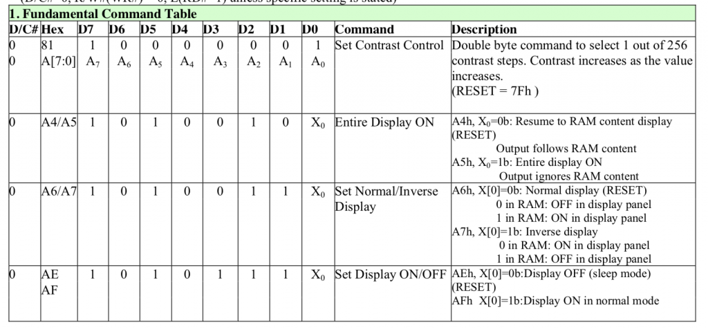
And my definitions in the C driver file:

////////////////////////////////////////////////////////////////////////
// Fundamental Command Table Page 28
////////////////////////////////////////////////////////////////////////
#define OLED_SETCONTRAST                              0x81
// 0x81 + 0-0xFF Contrast ... reset = 0x7F
// A4/A5 commands to resume displaying data
// A4 = Resume to RAM content display
// A5 = Ignore RAM content (but why?)
#define OLED_DISPLAYALLONRESUME                       0xA4
#define OLED_DISPLAYALLONIGNORE                       0xA5
// 0xA6/A7 Normal 1=white 0=black Inverse 0=white  1=black
#define OLED_DISPLAYNORMAL                            0xA6
#define OLED_DISPLAYINVERT                            0xA7
// 0xAE/AF are a pair to turn screen off/on
#define OLED_DISPLAYOFF                               0xAE
#define OLED_DISPLAYON                                0xAF

In the next section of the command table are the “Scrolling” commands.  It appears that this graphics chip was setup to display text that is 8-pixels high.  The scrolling commands will let you move the screen up/down and left/right to scroll automatically without having to update the the frame buffer.  In other words it can efficiently scroll the screen without a bunch of load on your MCU CPU or on the data bus between them.  The Adafruit graphics library provides the scrolling commands.  However, I am not using them with the Segger Library.
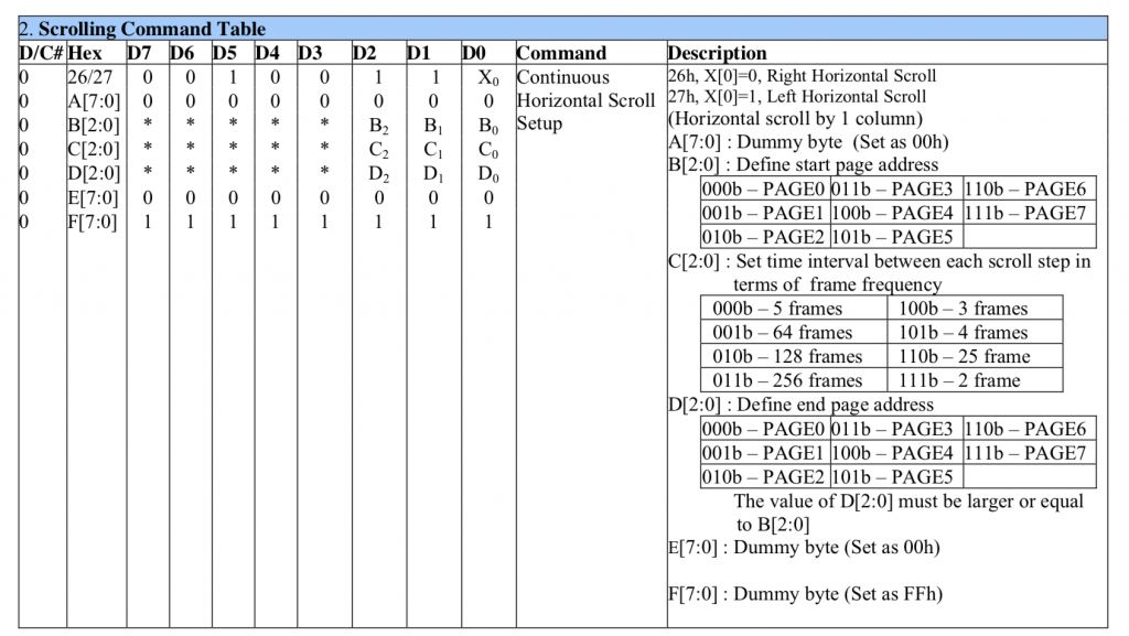
The next section has the commands to configure how your MCU writes data into the Graphics RAM aka the frame buffer. These commands fall into two categories.  First the address mode.  The address modes help you efficiently write the GDDRAM.  When you send data to the frame buffer you really don’t want to send

  • address, pixel, address, pixel, …

What you really would like to do is send

  • Address, pixel, pixel, pixel … (and have the address be automatically incremented

At first blush you might think… why do I need a mode?  Well there are some people who want the x address incremented… there are some people who want the y-address incremented and there are some people who want to have page address access.  And what do you do when you get to the end of a line? or a column or a page? and what does the end mean?

The second set of commands in this table are the commands to set the starting address before you write data.
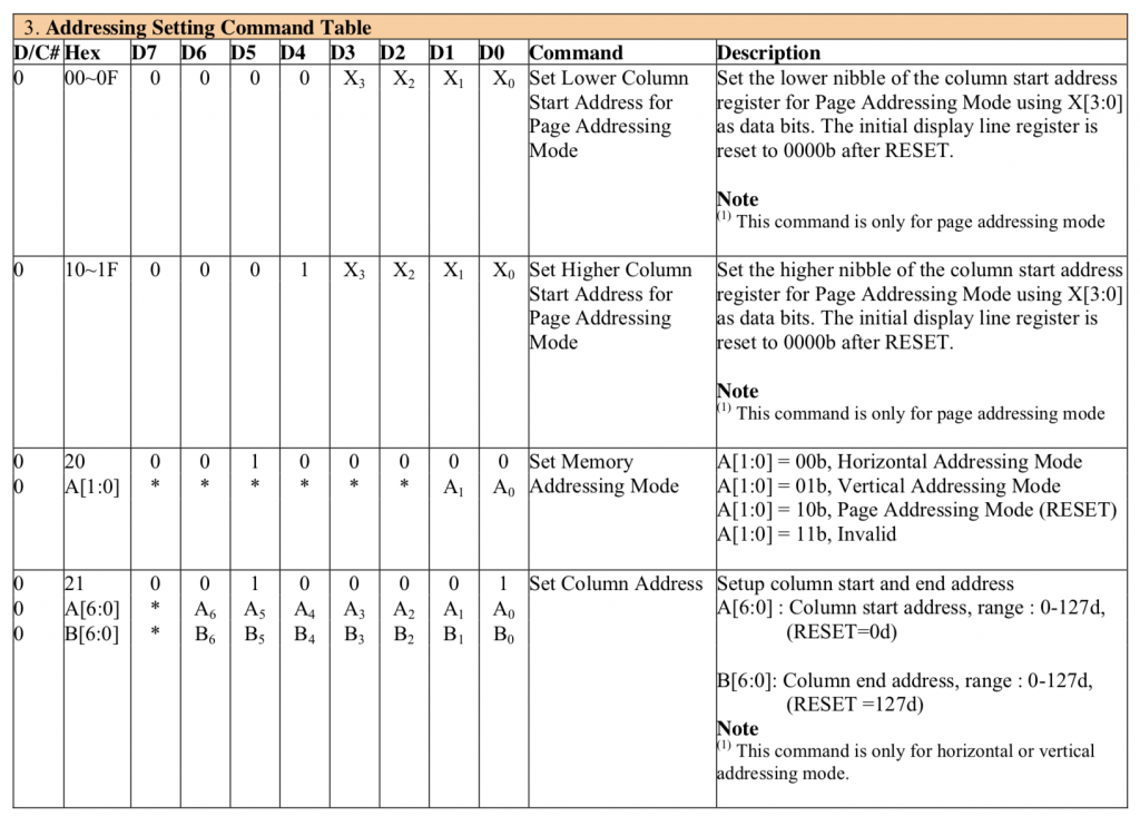
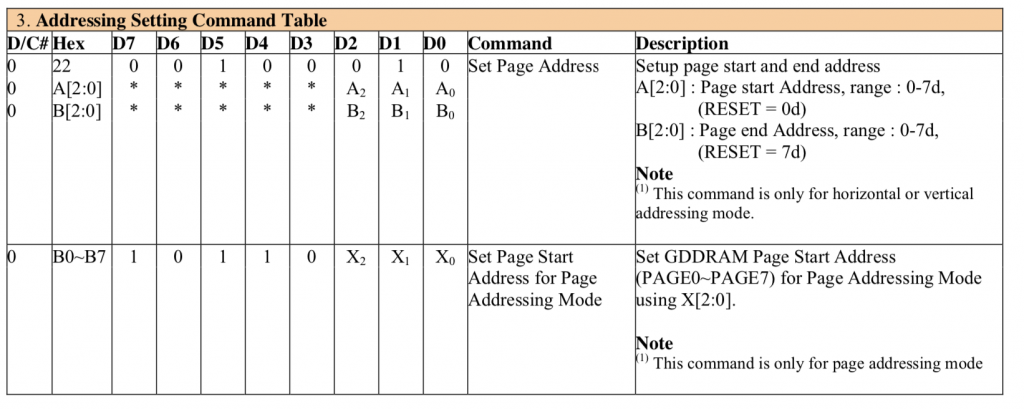
  

////////////////////////////////////////////////////////////////////////
// Address Setting Command Table
////////////////////////////////////////////////////////////////////////
// 00-0F - set lower nibble of page address
// 10-1F - set upper niddle of page address
#define OLED_SETMEMORYMODE                            0x20
#define OLED_SETMEMORYMODE_HORIZONTAL                 0x00
#define OLED_SETMEMORYMODE_VERTICAL                   0x01
#define OLED_SETMEMORYMODE_PAGE                       0x02
// 0x20 + 00 = horizontal, 01 = vertical 2= page >=3=illegal
// Only used for horizonal and vertical address modes
#define OLED_SETCOLUMNADDR                            0x21
// 2 byte Parameter
// 0-127 column start address 
// 0-127 column end address
#define OLED_SETPAGEADDR                              0x22
// 2 byte parameter
// 0-7 page start address
// 0-7 page end Address
// 0xB0 -0xB7 ..... Pick page 0-7

The hardware configuration registers allow the LED display maker to hookup the common and segment signals in an order that makes sense for the placement of the chip on the OLED glass.  For a 128×64 display there are at least 196 wires, so the routing of these wires may be a total pain in the ass depending on the location of the chip.  For instance the left and right might be swapped… or half the wires might come out on one side and the other half on the other side.  These registers allow the board designer flexibility in making these connections.  Commands 0xA0, 0xA1, 0xA8, 0xC0, 0xC8, 0xD3, 0xDa will all be fixed based on the layout.  You have no control and they need to be set correctly or something crazy will come out.
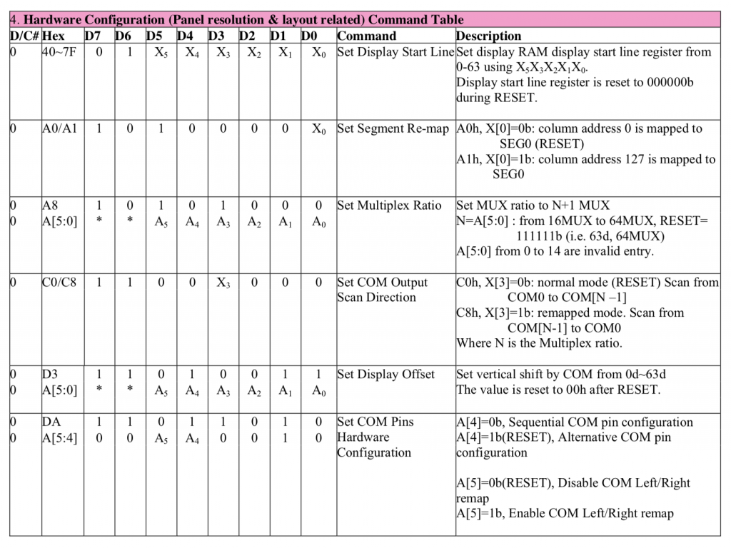
////////////////////////////////////////////////////////////////////////
// Hardware Configuration
////////////////////////////////////////////////////////////////////////
// 40-7F - set address startline from 0-127 (6-bits)
#define OLED_SETSTARTLINE_ZERO                        0x40
// Y Direction
#define OLED_SEGREMAPNORMAL                           0xA0
#define OLED_SEGREMAPINV                              0xA1
#define OLED_SETMULTIPLEX                             0xA8
// 0xA8, number of rows -1 ... e.g. 0xA8, 63
// X Direction
#define OLED_COMSCANINC                               0xC0
#define OLED_COMSCANDEC                               0xC8
// double byte with image wrap ...probably should be 0
#define OLED_SETDISPLAYOFFSET                         0xD3
// Double Byte Hardware com pins configuration
#define OLED_SETCOMPINS                               0xDA
// legal values 0x02, 0x12, 0x022, 0x032

The next sections of commands are part of the electrical configuration for the glass.

0xD5 essentially sets up the display update rate by 1) setting the display update clock frequency and 2) setting up a divider for that clock.

0xDB and 0xD9 sets up a parameter that is display dependent.  That being said I tried a bunch of different values and they all look the same to me.
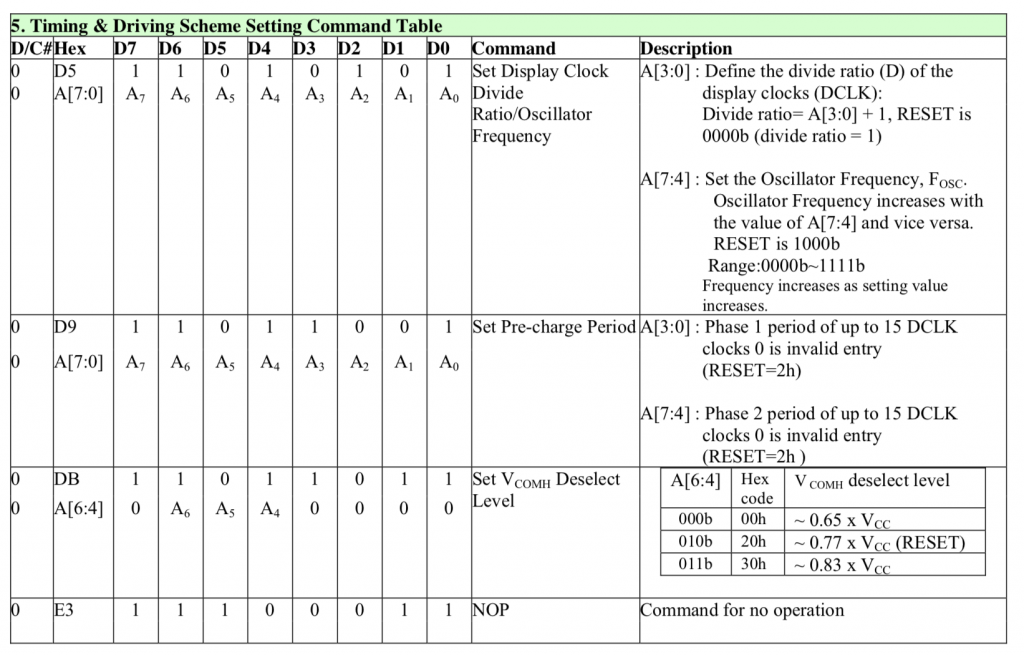
////////////////////////////////////////////////////////////////////////
// Timing and Driving Scheme Settings
////////////////////////////////////////////////////////////////////////
#define OLED_SETDISPLAYCLOCKDIV                       0xD5
#define OLED_SETPRECHARGE                             0xD9
#define OLED_SETVCOMDESELECT                          0xDB
#define OLED_NOP                                      0xE3

These displays require a high voltage to program the liquid crystal in the display.  That voltage can either be supplied by an external pin or by an internal charge pump.  All the displays that I have seen use an internal charge pump.
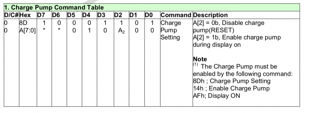
////////////////////////////////////////////////////////////////////////
// Charge Pump Regulator
////////////////////////////////////////////////////////////////////////
#define OLED_CHARGEPUMP                               0x8D
#define OLED_CHARGEPUMP_ON                            0x14
#define OLED_CHARGEPUMP_OFF                           0x10

The SSD1306 Graphics Data RAM

In order to actually get data to display on the screen you need to write 1’s and 0’s into the Graphics Data RAM that represents your image.  The memory is actually organized into 8 pages that are each 128 bits wide and 8 bits tall.  This means that if you write 0b10101010 to location (0,0) you will get the first 8 pixels in a column on the screen to be on,off,on,off,on,off,on,off.  Notice that I said vertical column and not row.  Here is a picture from the data sheet.  That shows the pages:
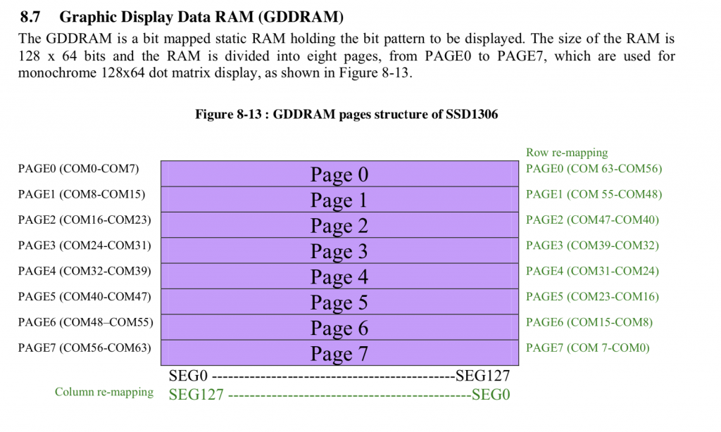
And then they show you in the data sheet that the pixels go down from the first row of the page.

In order to make the writing process easier and lower bandwidth the SSD1306 has three automatic addressing modes.

  • Horizontal – Set the page address start, end and the column start and end… bytes write 8 vertical pixels on the page. Each byte write advances the column until it wraps to the next page and resets the column to the “start”
  • Vertical – Set the page address start, end and the column start and end… bytes write 8 vertical pixels on the page.  Each byte write advances the page until it wraps vertically where it increments the column and resets the page back to the start page.
  • Page – Set the page address and column start/end.  Each byte writes vertically.  Wraps back onto the same page when it hits the end column.

In Horizontal and Vertical mode you

  • Set the range of columns that you want to write (using 0x22)
  • Set the range of pages you want to write (using 0x21)
  • Write bytes

In the page mode you

  • Set the page (remember you can only write one page at a time in page mode) using 0xB0-0xB7
  • Set the start column using 0x0? and 0x1?

Here is a picture from the data sheet of horizontal address mode:
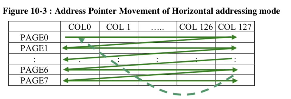
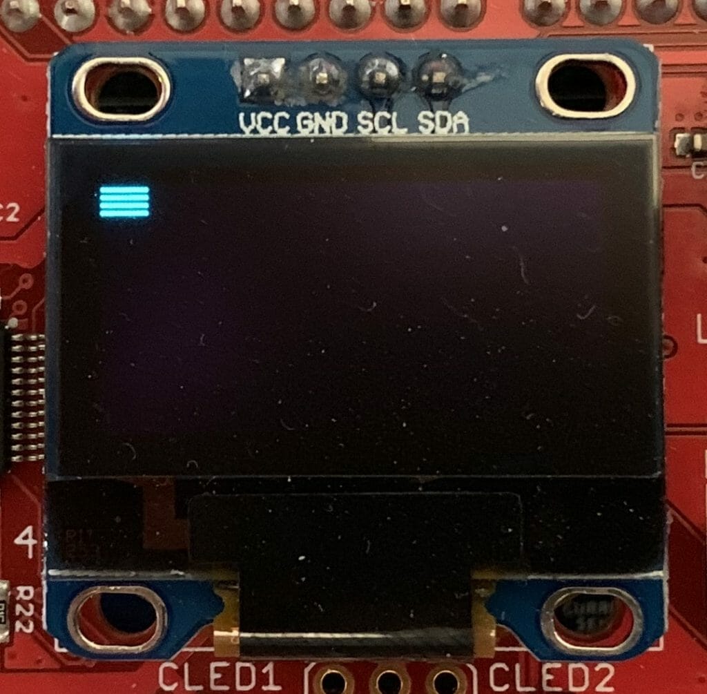
In this bit of example code I am saying to iterate through the pages 0->7… in other words all of the pages.  And to start in column 0.  This example will make 12 columns of pixels each 8 high starting a (0,0) on the screen…

    char horizontalExample[]= {
0xAE,
0x20, /// address mode
0x00, // Horizontal
0xA4,
0xAF,
0x22, //Set page address range
0,
7,
0x21, // column start and end address
0,
127,
};
I2C_WriteCmdStream(horizontalExample, sizeof(horizontalExample));
// Write twelve bytes onto screen with 0b10101010
for(int i=0;i<12;i++)
I2C_WriteData(0xAA);

Here is a picture of what it does.
Here is a picture from the data sheet of vertical address mode:
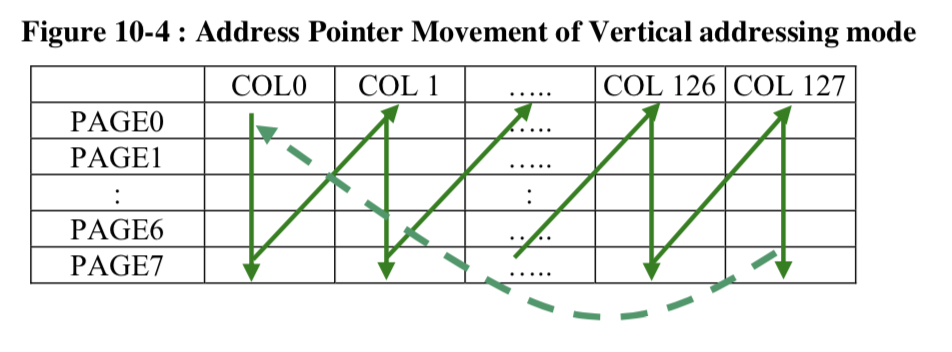
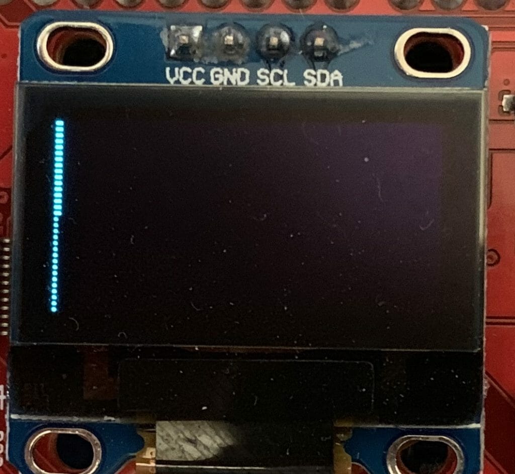
This example code sets the page range to 0–>7  (the whole screen) and the column range 0–>127 (the whole screen).  Then writes 12 bytes.  You can see it wrap at the bottom and move back to page 0 column 1.

    char verticalExample[]= {
0xAE,
0x20, /// address mode
0x01, //  vertical
0xA4,
0xAF,
0x22, //Set page address range
0,
7,
0x21, // column start and end address
0,
127,
};
I2C_WriteCmdStream(verticalExample, sizeof(verticalExample));
// Write twelve bytes onto screen with 0b10101010
for(int i=0;i<12;i++)
I2C_WriteData(0xAA); 


In page mode you just set the page and the start and end column.  0xB0 means page 0, 0xB1 means page 1… 0xB7 means page 7.

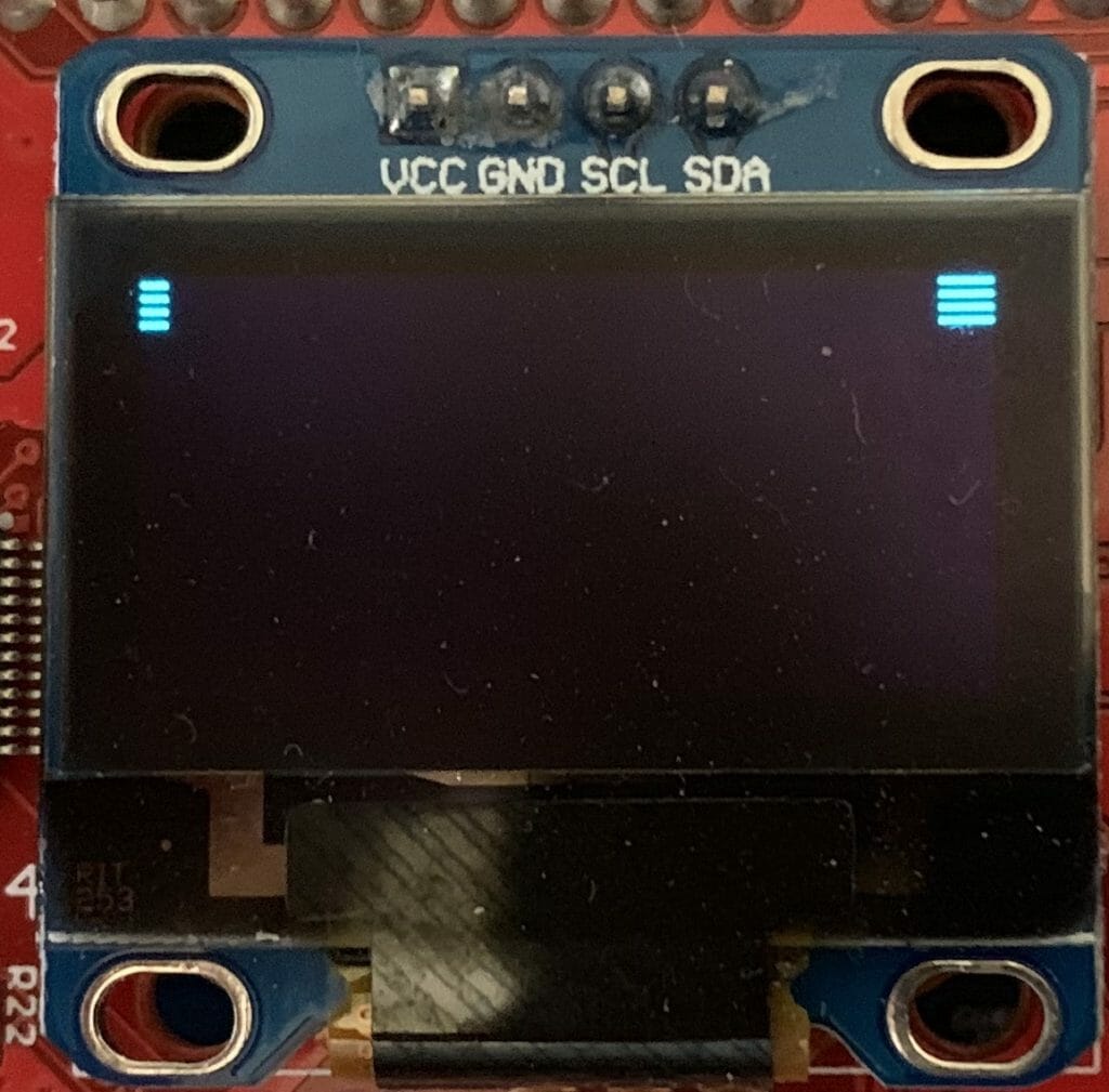
You can see that I started from column 0x78 (meaning column 120) and that it wraps back to column 0 on the SAME page.

    char pageExample[]= {
0xAE,
0x20, // address mode
0x02, // Page mode
0xA4, // Resume from ram
0xAF, // Screen on
0xB0, // Start from page 0
// Start from column 0x78 aka 120
0x08, // Column lower nibble address
0x17  // Column upper nibble address
};
I2C_WriteCmdStream(pageExample, sizeof(pageExample));
// Write twelve bytes onto screen with 0b10101010
for(int i=0;i<12;i++)
I2C_WriteData(0xAA);
Here is what it looks like.
Reading from the Frame Buffer

Now that you know how to write to the Frame Buffer, the next question is how do you read?  For instance if you want to turn on 1 pixel (of a byte) but leave the others alone can you do this? The answer is NO.  In serial mode the device only writes.  In all of the Graphics libraries that I have seen they handle this by having a Frame Buffer in the MCU as well.  Duplicated resources… oh well.

My Initialization Sequence

I have a function that writes an array of bytes to the command registers.  So for me to initialize the screen I just need to set up that array.  Here is my best known setup.

    const char initializeCmds[]={
//////// Fundamental Commands
OLED_DISPLAYOFF,          // 0xAE Screen Off
OLED_SETCONTRAST,         // 0x81 Set contrast control
0x7F,                     // 0-FF ... default half way
OLED_DISPLAYNORMAL,       // 0xA6, //Set normal display 
//////// Scrolling Commands
OLED_DEACTIVATE_SCROLL,   // Deactive scroll
//////// Addressing Commands
OLED_SETMEMORYMODE,       // 0x20, //Set memory address mode
OLED_SETMEMORYMODE_PAGE,  // Page
//////// Hardware Configuration Commands
OLED_SEGREMAPINV,         // 0xA1, //Set segment re-map 
OLED_SETMULTIPLEX,        // 0xA8 Set multiplex ratio
0x3F,                     // Vertical Size - 1
OLED_COMSCANDEC,          // 0xC0 Set COM output scan direction
OLED_SETDISPLAYOFFSET,    // 0xD3 Set Display Offset
0x00,                     //
OLED_SETCOMPINS,          // 0xDA Set COM pins hardware configuration
0x12,                     // Alternate com config & disable com left/right
//////// Timing and Driving Settings
OLED_SETDISPLAYCLOCKDIV,  // 0xD5 Set display oscillator frequency 0-0xF /clock divide ratio 0-0xF
0x80,                     // Default value
OLED_SETPRECHARGE,        // 0xD9 Set pre-changed period
0x22,                     // Default 0x22
OLED_SETVCOMDESELECT,     // 0xDB, //Set VCOMH Deselected level
0x20,                     // Default 
//////// Charge pump regulator
OLED_CHARGEPUMP,          // 0x8D Set charge pump
OLED_CHARGEPUMP_ON,       // 0x14 VCC generated by internal DC/DC circuit
// Turn the screen back on...       
OLED_DISPLAYALLONRESUME,  // 0xA4, //Set entire display on/off
OLED_DISPLAYON,           // 0xAF  //Set display on
};

Some Other Initialization Sequences

If you look around you will find many different SSD1306 libraries.  You can run this search on github.

Here is one example from https://github.com/vadzimyatskevich/SSD1306/blob/master/src/ssd1306.c  This is pretty much the same as mine except that the author put them in some other order than the data sheet.  I am not a huge fan of “ssd1306Command( SSD1306_SEGREMAP | 0x1)” but it does work.

void  ssd1306Init(uint8_t vccstate)
{
_font = (FONT_INFO*)&ubuntuMono_24ptFontInfo;
// Initialisation sequence
ssd1306TurnOff();
//  1. set mux ratio
ssd1306Command(   SSD1306_SETMULTIPLEX );
ssd1306Command(   0x3F );
//  2. set display offset
ssd1306Command(   SSD1306_SETDISPLAYOFFSET );
ssd1306Command(   0x0 );
//  3. set display start line
ssd1306Command(   SSD1306_SETSTARTLINE | 0x0 ); 
ssd1306Command( SSD1306_MEMORYMODE);                    // 0x20
ssd1306Command( 0x00);                                  // 0x0 act like ks0108
//  4. set Segment re-map A0h/A1h    
ssd1306Command(   SSD1306_SEGREMAP | 0x1);
//   5. Set COM Output Scan Direction C0h/C8h
ssd1306Command(   SSD1306_COMSCANDEC);
//  6. Set COM Pins hardware configuration DAh, 12
ssd1306Command(   SSD1306_SETCOMPINS);
ssd1306Command(   0x12);
//  7. Set Contrast Control 81h, 7Fh
ssd1306Command(   SSD1306_SETCONTRAST );
if (vccstate == SSD1306_EXTERNALVCC) { 
ssd1306Command(   0x9F );
} else { 
ssd1306Command(   0xff );
}
//  8. Disable Entire Display On A4h
ssd1306Command(   SSD1306_DISPLAYALLON_RESUME);
//  9. Set Normal Display A6h 
ssd1306Command(   SSD1306_NORMALDISPLAY);
//  10. Set Osc Frequency  D5h, 80h 
ssd1306Command(   SSD1306_SETDISPLAYCLOCKDIV);
ssd1306Command(   0x80);
//  11. Enable charge pump regulator 8Dh, 14h 
ssd1306Command(   SSD1306_CHARGEPUMP );
if (vccstate == SSD1306_EXTERNALVCC) { 
ssd1306Command(   0x10);
} else { 
ssd1306Command(   0x14);
}
//  12. Display On AFh 
ssd1306TurnOn();
}

Here is another example from git@github.com:lexus2k/ssd1306.git

https://github.com/lexus2k/ssd1306/blob/master/src/lcd/oled_ssd1306.c

Honestly if I had found this originally I would not have gone to all the trouble.

static const uint8_t PROGMEM s_oled128x64_initData[] =
{
#ifdef SDL_EMULATION
SDL_LCD_SSD1306,
0x00,
#endif
SSD1306_DISPLAYOFF, // display off
SSD1306_MEMORYMODE, HORIZONTAL_ADDRESSING_MODE, // Page Addressing mode
SSD1306_COMSCANDEC,             // Scan from 127 to 0 (Reverse scan)
SSD1306_SETSTARTLINE | 0x00,    // First line to start scanning from
SSD1306_SETCONTRAST, 0x7F,      // contast value to 0x7F according to datasheet
SSD1306_SEGREMAP | 0x01,        // Use reverse mapping. 0x00 - is normal mapping
SSD1306_NORMALDISPLAY,
SSD1306_SETMULTIPLEX, 63,       // Reset to default MUX. See datasheet
SSD1306_SETDISPLAYOFFSET, 0x00, // no offset
SSD1306_SETDISPLAYCLOCKDIV, 0x80,// set to default ratio/osc frequency
SSD1306_SETPRECHARGE, 0x22,     // switch precharge to 0x22 // 0xF1
SSD1306_SETCOMPINS, 0x12,       // set divide ratio
SSD1306_SETVCOMDETECT, 0x20,    // vcom deselect to 0x20 // 0x40
SSD1306_CHARGEPUMP, 0x14,       // Enable charge pump
SSD1306_DISPLAYALLON_RESUME,
SSD1306_DISPLAYON,
};

Debug: Test the Hardware

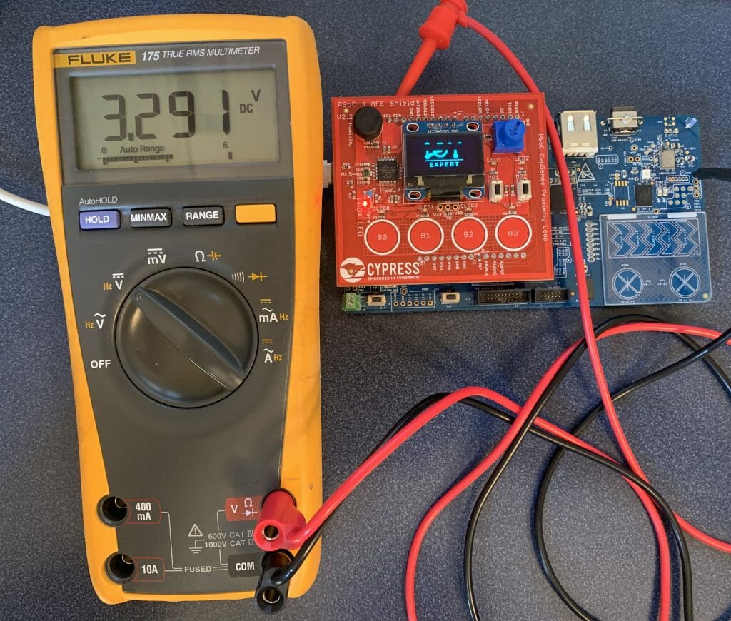
If a your screen is not working, the first thing to do is use a multimeter and make sure that VCC=SCL=SDA=3.3V.  (in the picture below my camera caught the screen refresh partially through… It looks fine at normal speed).  I have the red probe attached to the SCL.
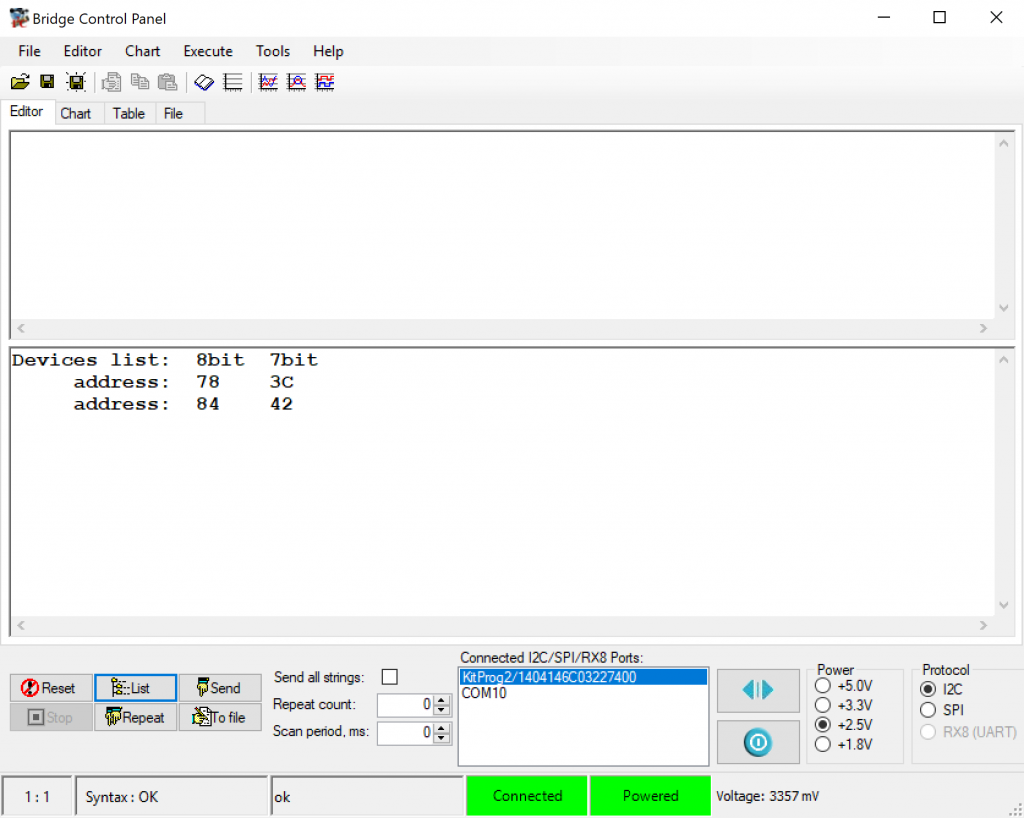
I would then run the bridge control panel and make sure that the device is responding.  You can do this by pressing “List”.  In the picture below you can see that there are two devices attached to the bus,  my screen is set to 0x78/0x3C.
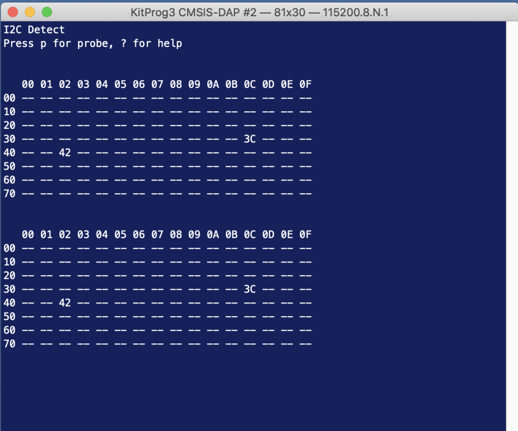
If you don’t have the bridge control panel then you can implement I2Cdetect using your development kit.   Read about it here.
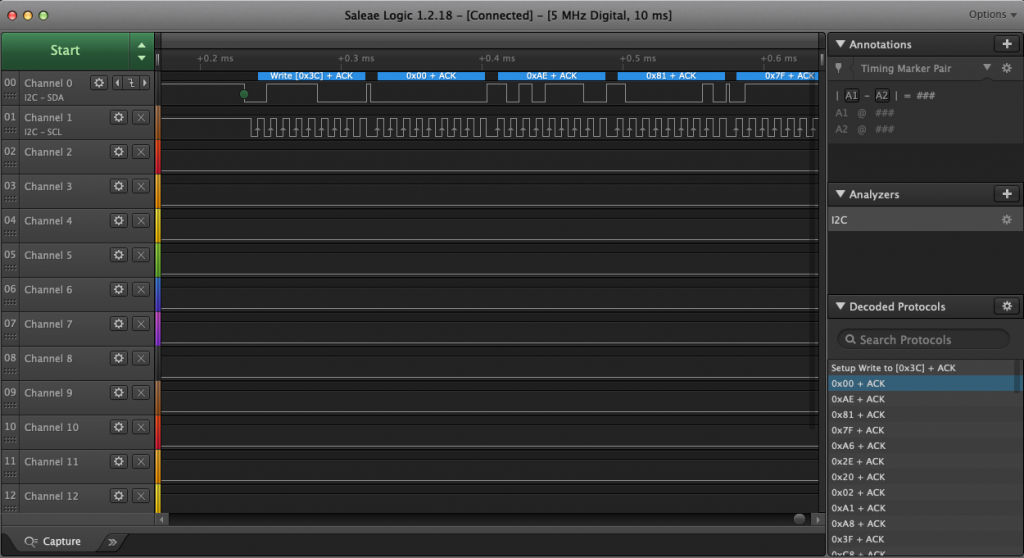
The next thing to do is attach a logic analyzer and make sure that the startup commands are coming out of your MCU correctly.  Notice that the 00, 0xAE, 0x81… are exactly the configuration sequence that I wrote in the driver code above.
Debug: Test the Firmware

If your screen is still not working here are some problems and what to do about them.

  • Speckled Screen
  • Solid Screen
  • Screen Flipped in the Y direction
  • Screen Flipped in the X Direction
  • Screen Flipped in both Directions
  • Screen is Inverted
  • Image is Partially off the Screen
  • Image is Wrapped on the Screen
  • Black Screen
  • Screen Has Gone Crazy

Speckled Screen

If you have the speckled screen this means that your screen is displaying an uninitialized frame buffer which the SSD people call the GDDRAM.  These are basically the random 0 and 1s that are the startup values in the SSD1306.  If this is happening then your graphic data is probably not being transferred between your MCU and the SSD1306.  This almost certainly means you have a problem in your porting layer.
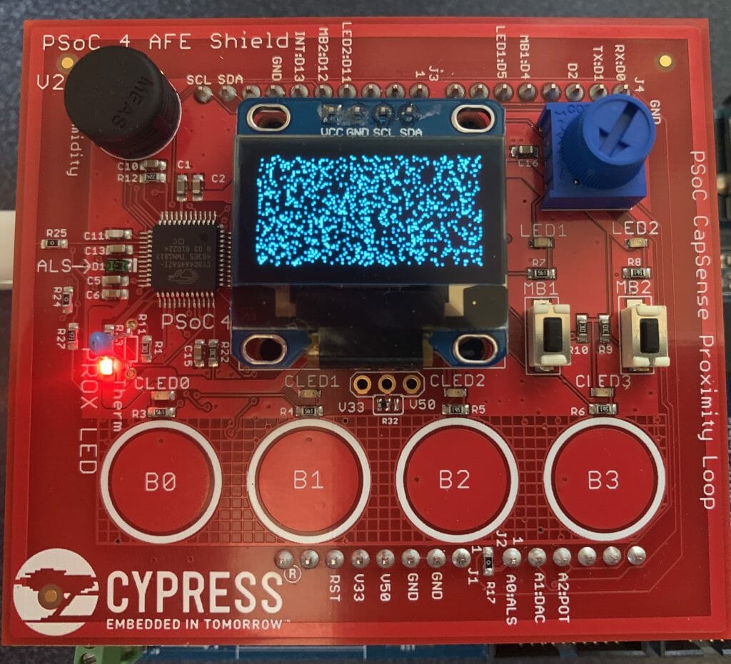
Speckled Screen

If your screen is solid white that probably means you turned the screen back on without resuming from the graphics ram.  You did this:

OLED_DISPLAYALLONIGNORE,  // 0xA5, //Set entire display on/off

instead of this:

OLED_DISPLAYALLONRESUME,  // 0xA4, //Set entire display on/off
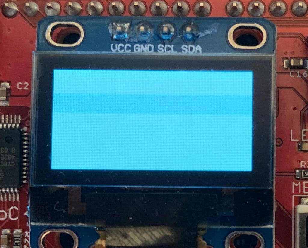
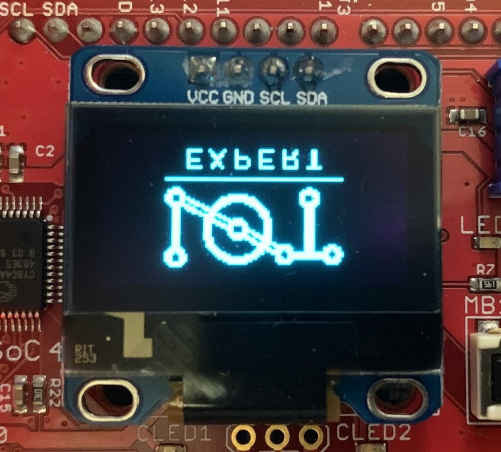
Screen Flipped in the Y direction

The commands C0/C8 set the direction in which the com lines are scanned.  Either from top to bottom or bottom to top.  Change C0–>C8 to the other way.
#define OLED_COMSCANINC                               0xC0
#define OLED_COMSCANDEC                               0xC8
Screen Flipped in the X Direction

In the X-Direction the A0/A1 set the configuration of scanning.  Try using A0–>A8 or the other way.

// X Direction Scanning 
#define OLED_SEGREMAPNORMAL                           0xA0
#define OLED_SEGREMAPINV                              0xA1
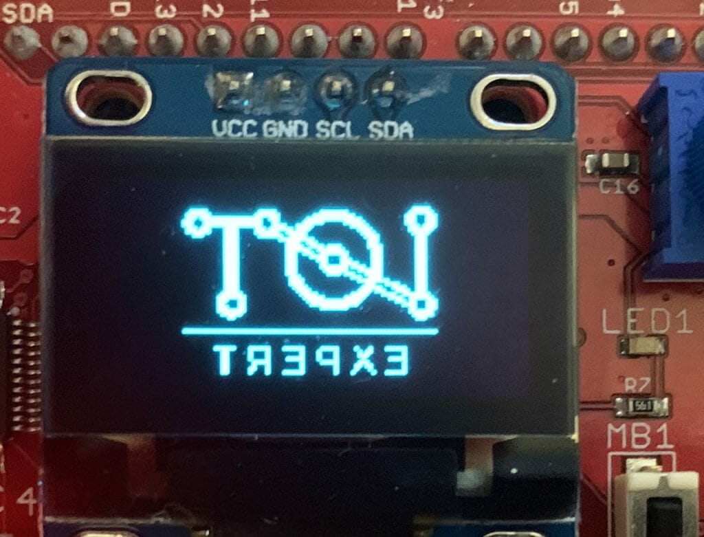
Screen Flipped in both Directions

If it is flipped in both X and Y direction then flip both of the direction registers.

// Y Direction
#define OLED_SEGREMAPNORMAL                           0xA0
#define OLED_SEGREMAPINV                              0xA1
// X Direction
#define OLED_COMSCANINC                               0xC0
#define OLED_COMSCANDEC                               0xC8
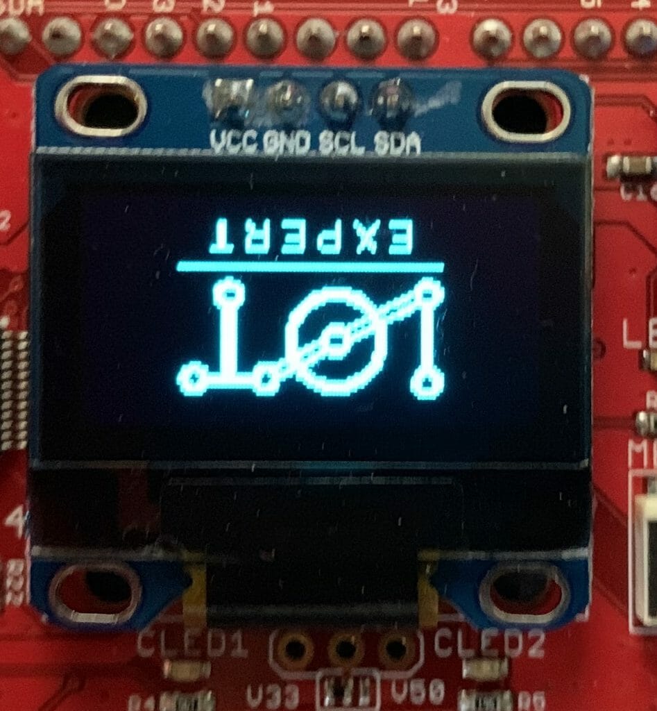
Screen is Inverted

If your screen is inverted then try A8–>A6

#define OLED_DISPLAYNORMAL                            0xA6
#define OLED_DISPLAYINVERT                            0xA7
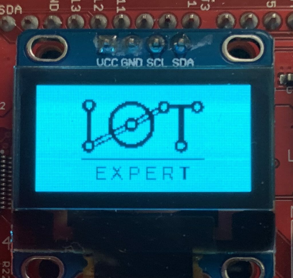
Image is Partially off the Screen

If your image is off the screen the you probably have the wrong value for MULTIPLEX.

#define OLED_SETMULTIPLEX                             0xA8

The parameter is supposed to be the number of lines on the screen -1.  In my case the screen is 128×64 so my valued should be 63 aka 0x3F

        OLED_SETMULTIPLEX,        // 0xA8 Set multiplex ratio
0x3F,                     // Vertical Size - 1
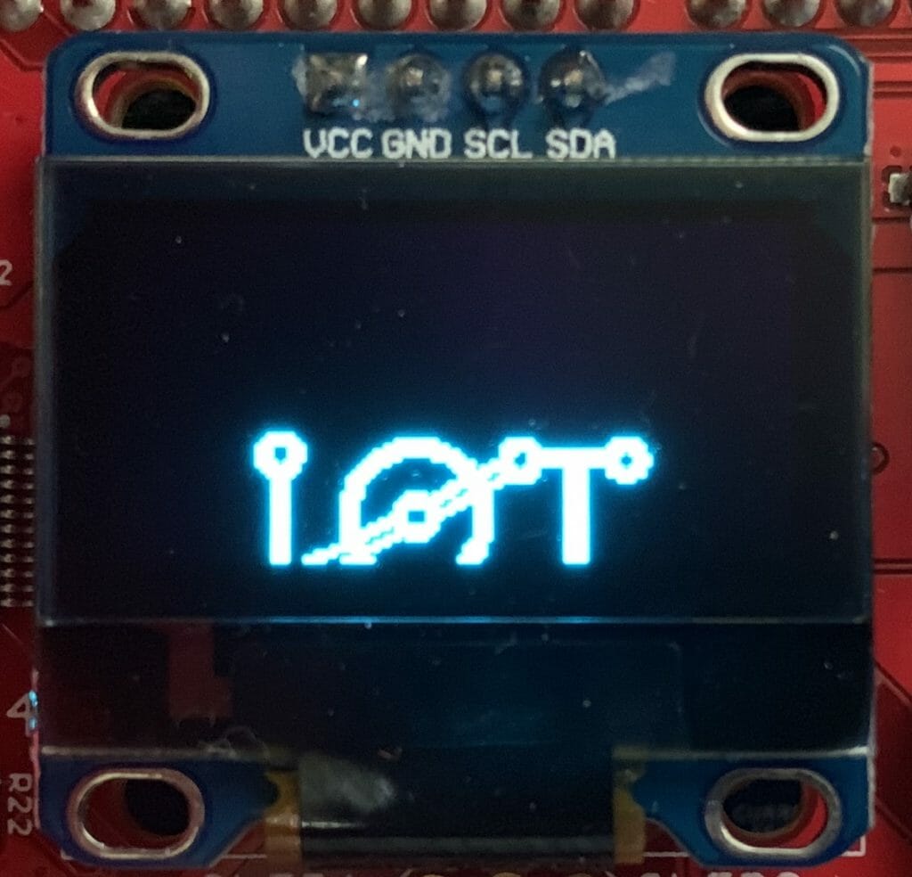
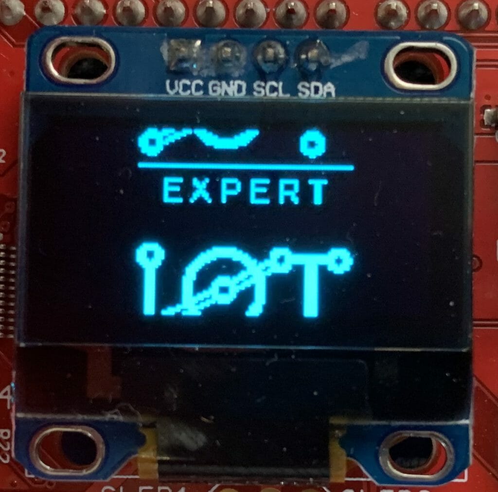
Image is Wrapped on the Screen

// Double byte CMD image wrap ...probably should be 0
#define OLED_SETDISPLAYOFFSET                         0xD3

The offset value allows the board designer to hook up the rows in a crazy fashion.   My screen has the top row to the top row number.

        OLED_SETDISPLAYOFFSET,    // 0xD3 Set Display Offset
0x00,                     //
\

Black Screen

If you screen is totally dead…
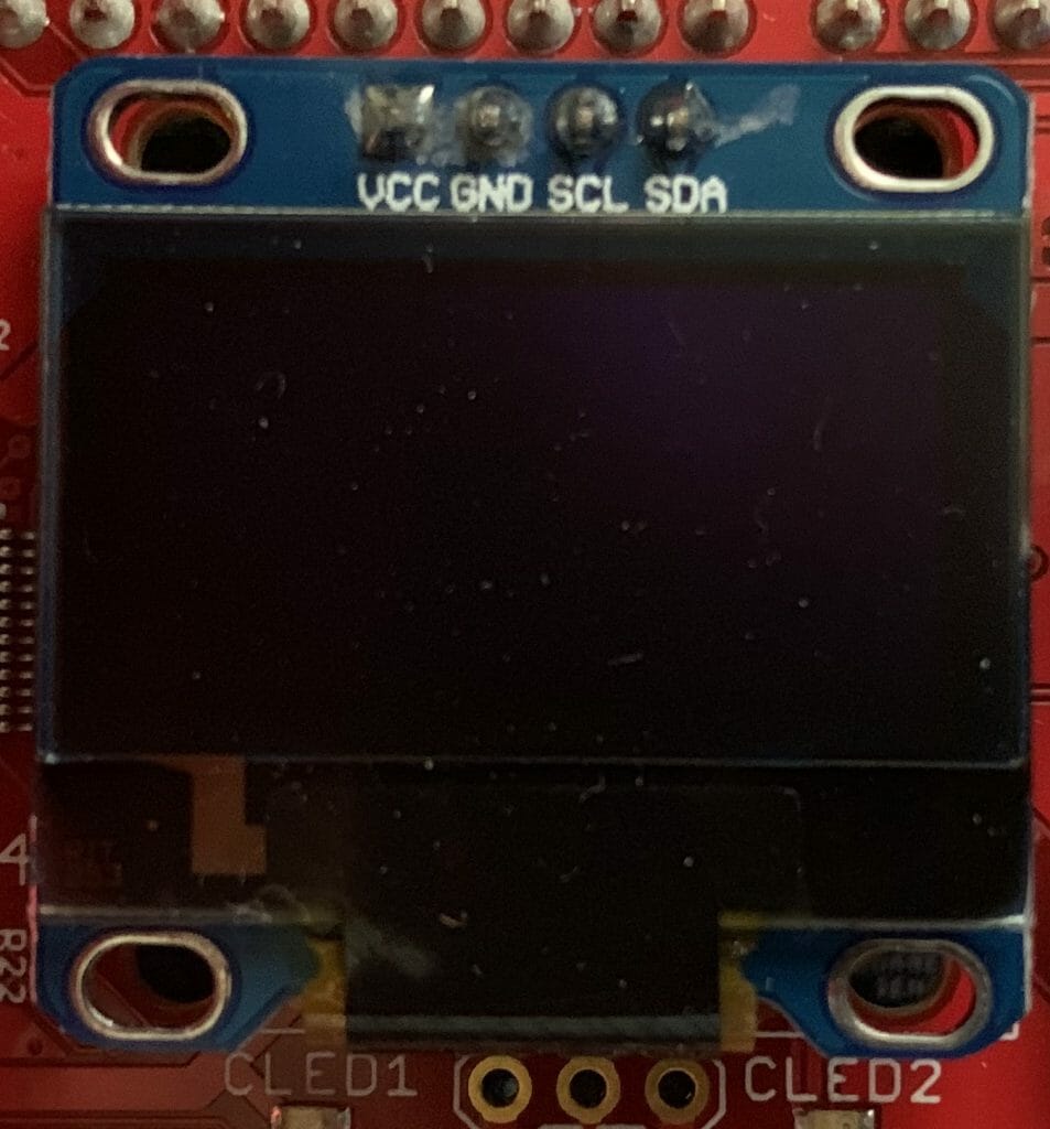
Then the charge pump may be off

        //////// Charge pump regulator
OLED_CHARGEPUMP,          // 0x8D Set charge pump
0x14,                     // VCC generated by internal DC/DC circuit

or maybe the screen is off… try turning it on.

        OLED_DISPLAYON,           // 0xAF  //Set display on

or maybe you haven’t displayed anything. The screen is off trying sending a screen invert

#define OLED_DISPLAYINVERT                            0xA7

The Screen Has Gone Crazy

The register 0xDA SetComPins register will make some crazy results of it isn’t set correctly.  For my 0.96″ inch screen it needs to be set to 0x12

// Double Byte Hardware com pins configuration
#define OLED_SETCOMPINS                               0xDA
// legal values 0x02, 0x12, 0x022, 0x032

This is what happens with 0x02 [If you see the note below from Ivan, 0x02 is apparently for 128×32 and this screen is 128×64=0x12]
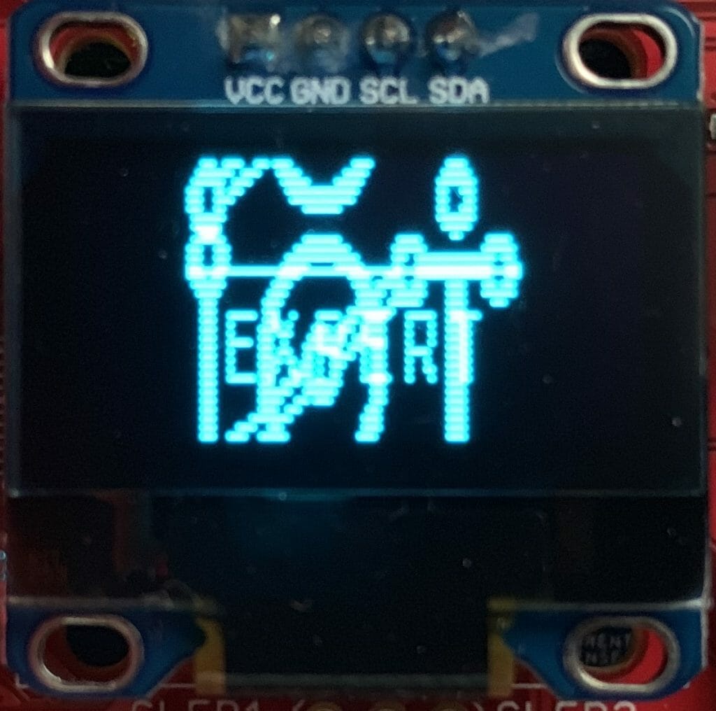
And 0x22
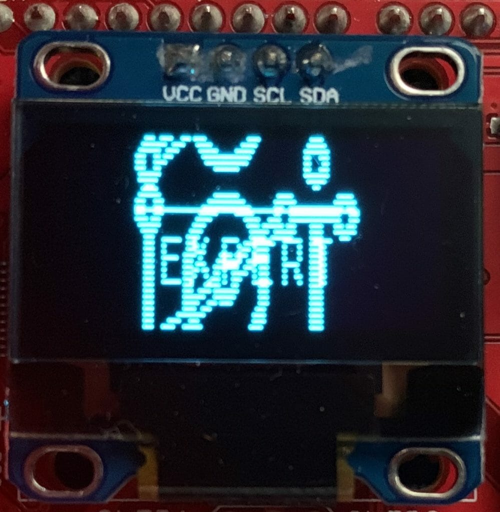
Finally 0x32
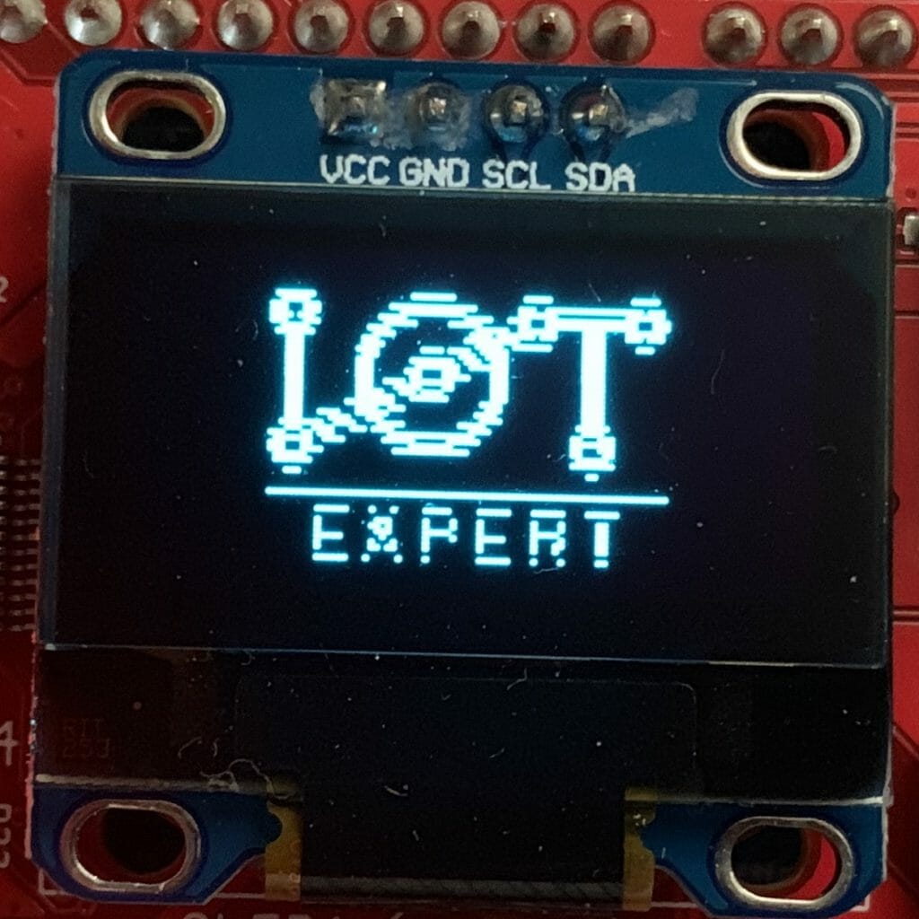
This was absolutely the craziest rabbit hole that I have ventured down. Nicholas has talked to me 10 times about doing this and he thinks I’m crazy.  Oh well.

I2C Detect with PSoC 6

Summary

In this article I explain how to use a PSoC 6 SCB to implement I2C Detect.

Recently,  I wrote about using the Raspberry PI I2C bus master to talk to a PSoC 4 I2C Slave.  In that project I used a program on the Raspberry Pi called “I2CDetect” which probes the I2C bus and prints out devices that are attached.  Here is what the output looks like:

pi@iotexpertpi:~/pyGetData $ i2cdetect -y 1
0  1  2  3  4  5  6  7  8  9  a  b  c  d  e  f
00:          -- -- -- -- -- 08 -- -- -- -- -- -- -- 
10: -- -- -- -- -- -- -- -- -- -- -- -- -- -- -- -- 
20: -- -- -- -- -- -- -- -- -- -- -- -- -- -- -- -- 
30: -- -- -- -- -- -- -- -- -- -- -- -- -- -- -- -- 
40: -- -- -- -- -- -- -- -- -- -- -- -- -- -- -- -- 
50: -- -- -- -- -- -- -- -- -- -- -- -- -- -- -- -- 
60: -- -- -- -- -- -- -- -- -- -- -- -- -- -- -- -- 
70: -- -- -- -- -- -- -- --                         
pi@iotexpertpi:~/pyGetData $ 

You can do this same thing by using the bridge control panel (which comes as part of PSoC Creator).  I have used this program a bunch of times on this blog and you can search for all of those here.

But how does it work?  Simple, it uses the I2C bus master to iterate through all of the addresses 0-0x7F and

  • Send a start
  • Send the address
  • Send a write
  • If you get ACK print out the address
  • If you get a NAK print out —
  • Send a stop

You can easily do this using the PSoC 6 (or 4) Serial Communication Block.  Here is an implementation in Modus Toolbox 1.1 where I

  1. Create the project and configure the middleware
  2. Implement probe
  3. Implement the main loop
  4. Test

Create the Project, Configure the Hardware and Middleware

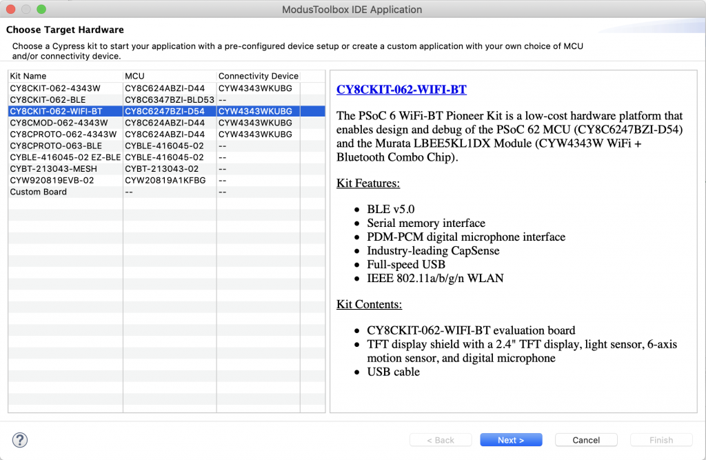
Start by creating a new project.  In this case I have a CY8CKIT_062_WIFI_BT.  But this will work on any PSoC6s.

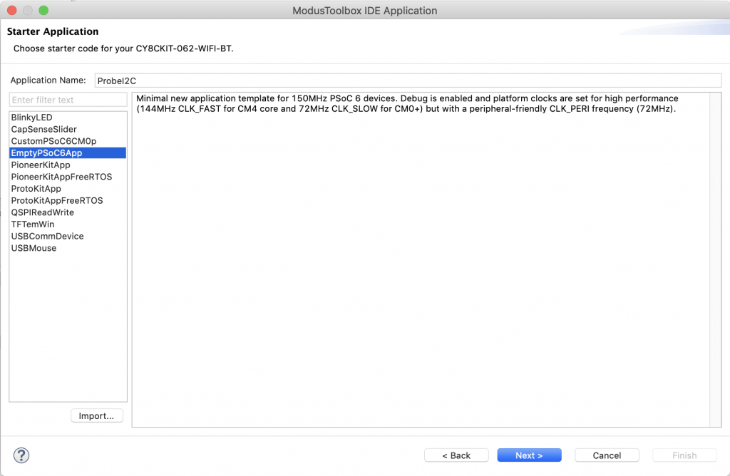
I just start with the empty project.

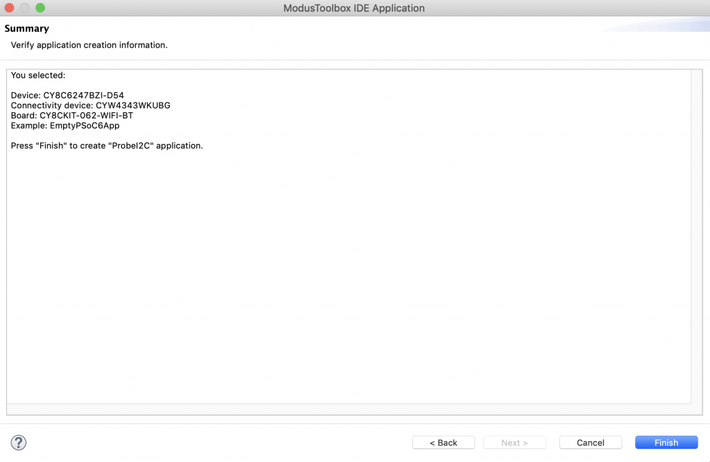
Click Finish to make the project.

Double click on the “design.modus” or click “Configure Device” from the quick panel.
Here is the design.modus

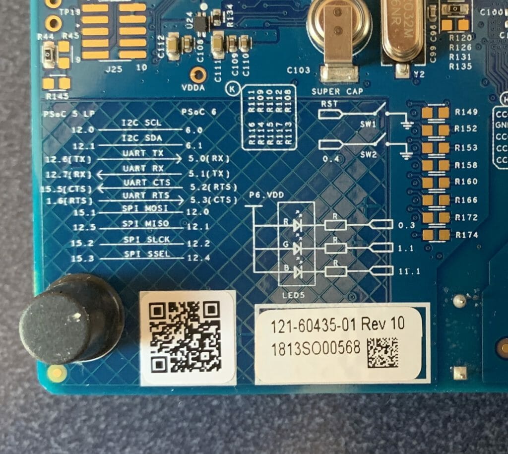
When the configurator starts you need to enable the SCB that is connected to the Kitprog bridge.  You can figure this out by looking on the back of your development kit where there is a little table.  In the picture below you can see that the UART is connected to P5.0 and P5.1
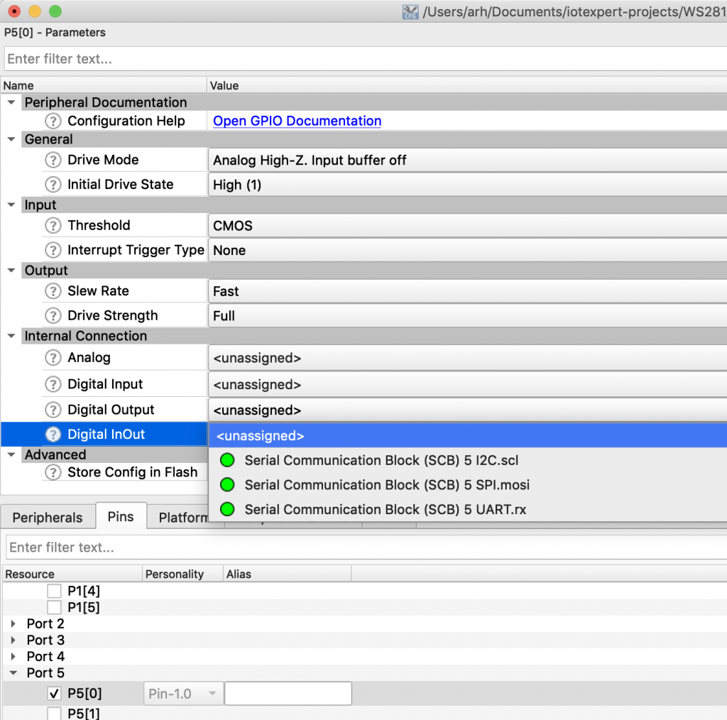
Which SCB is P5.0/P5.1 connected to?  The answer is SCB5.  But how do you figure that out?  Click on the Pins table.  Then select P5[0] and then Digital In/Out and you can see that the SCB 5 UART RX is attached to that pin.

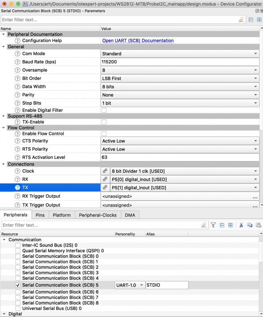
Cancel that and go to SCB 5.  Enable it.  Select the UART personality.  Give it the name “STDIO”.  Pick a clock divider (in this case I picked 1… but it doesn’t matter as the configurator will pick the right divide value).  Then pick the Rx/Tx to be P5[0] and P5[1]

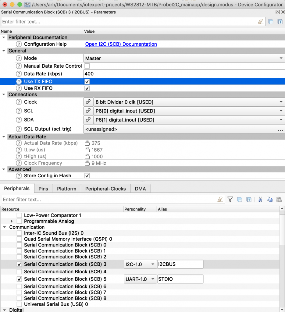
Next you need to turn on the I2C Master.  On my board the SCB bus that I want to use is connected to P6[0] P6[1].  The bus I want is the standard Arduino I2C pins.  I can see that from the back of the development kit (just like above).  These pins are connected to SCB3 (which I figured out just like I did with the UART).

Enable SCB3. Select the I2C personality.  Give it the name I2CBUS. Select Master. Make it 400kbs.  Assign a clock divider (in this case 0).  Assign the SCL and SDA pins to P6[0] and P6[1]

Hit save.

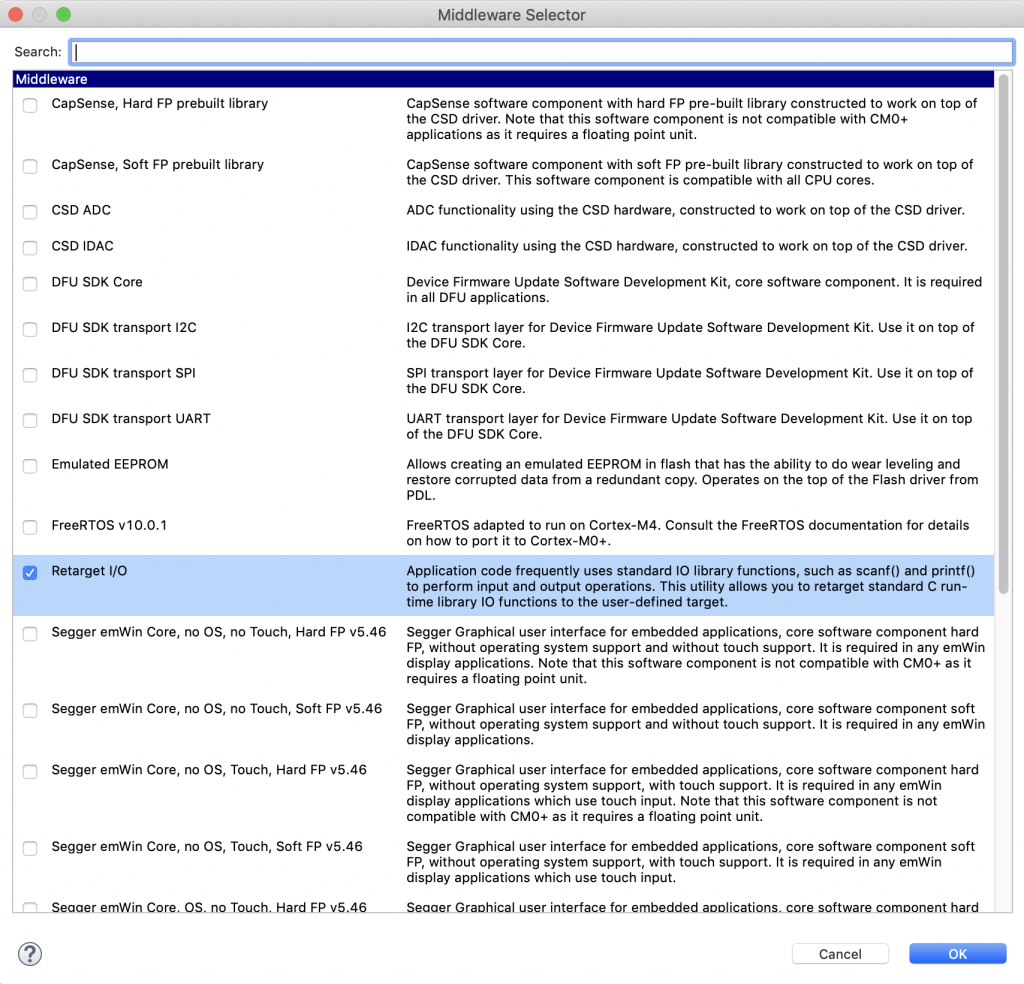
For this example I want to be able to use printf.  So I right click on the “Select Middleware” from the quick panel.
Then I add “Retarget I/O”.

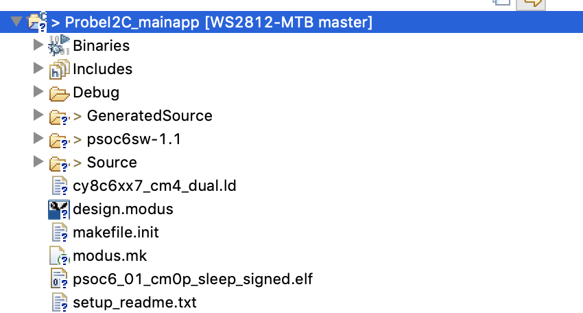
Once that is done you will have “stdio_user.h” and “stdio_user.c” in your Source directory:

In order to turn on printf you need to modify stdio_user.h so that it uses the right SCB for printing.  But what is that SCB?  Simple we called it “STDIO” in the configurator.  Here is the change you need to make:

#include "cy_device_headers.h"
#include "cycfg.h"
/* Must remain uncommented to use this utility */
#define IO_STDOUT_ENABLE
#define IO_STDIN_ENABLE
#define IO_STDOUT_UART      STDIO_HW
#define IO_STDIN_UART       STDIO_HW

Edit main.c.  Add a function called “probe” which will

  1. Print a header (line 15-19)
  2. Iterate through all of the addresses (line 22)
  3. If you have hit the end of a line setup the next line (lines 24-25)
  4. Send a start and write (line 27)
  5. If you get a CY_SCB_SUCCESS then print the address (line 30)
  6. Otherwise print a “–” (line 34)
// Print the probe table
void probe()
{
uint32_t rval;
// Setup the screen and print the header
printf("\n\n   ");
for(unsigned int i=0;i<0x10;i++)
{
printf("%02X ",i);
}
// Iterate through the address starting at 0x00
for(uint32_t i2caddress=0;i2caddress<0x80;i2caddress++)
{
if(i2caddress % 0x10 == 0 )
printf("\n%02X ",(unsigned int)i2caddress);
rval = Cy_SCB_I2C_MasterSendStart(I2CBUS_HW,i2caddress,CY_SCB_I2C_WRITE_XFER,10,&I2CBUS_context);
if(rval == CY_SCB_I2C_SUCCESS ) // If you get ACK then print the address
{
printf("%02X ",(unsigned int)i2caddress);
}
else //  Otherwise print a --
{
printf("-- ");
}
Cy_SCB_I2C_MasterSendStop(I2CBUS_HW,0,&I2CBUS_context);
}
printf("\n");
}

For all of this to work you need to have two context global variables which are used by PDL to save state.

cy_stc_scb_uart_context_t STDIO_context;
cy_stc_scb_i2c_context_t I2CBUS_context;

Create a main function to:

  • initialize the two SCBs 45-50
  • The API call setvbuf on line 47 just turns off buffering on stdin so that every character will come directly to getc
  • print the header (line 54-56)
  • the clear screen line just send the VT100 escape sequence to clear the screen and go home.  Almost all terminal programs are essentially VT100 emulators.
  • run the probe one time (line 57)
  • go into an infinite loop looking for key presses (line 59-61)
  • if they press ‘p’ then call the probe function (line 64)
  • if they press ‘?’ then printout help (line 69)
int main(void)
{
/* Set up the device based on configurator selections */
init_cycfg_all();
Cy_SCB_UART_Init(STDIO_HW,&STDIO_config,&STDIO_context);
Cy_SCB_UART_Enable(STDIO_HW);
setvbuf( stdin, NULL, _IONBF, 0 ); // Turn off stdin buffering
Cy_SCB_I2C_Init(I2CBUS_HW,&I2CBUS_config,&I2CBUS_context);
Cy_SCB_I2C_Enable(I2CBUS_HW);
__enable_irq();
printf("\033[2J\033[H"); // clear the screen
printf("I2C Detect\n");
printf("Press p for probe, ? for help\n");
probe(); // Do an initial probe
while(1)
{
char c = getchar();
switch(c)
{
case 'p':
probe();
break;
case '?':
printf("------------------\n");
printf("Command\n");
printf("p\tProbe\n");
printf("?\tHelp\n");
break;
}
}
}

Once I program this I get a nice output.  Notice that these are all 7-bit addresses.

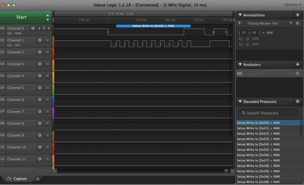
If I connect a logic analyzer you can see the bus behavior.  Start with a bunch of 0 – nak, 1-nak ….

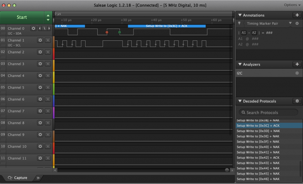
until finally it hits 3C when it get an ACK

Here is the whole program

#include "cy_device_headers.h"
#include "cycfg.h"
#include <stdio.h>
cy_stc_scb_uart_context_t STDIO_context;
cy_stc_scb_i2c_context_t I2CBUS_context;
// Print the probe table
void probe()
{
uint32_t rval;
// Setup the screen and print the header
printf("\n\n   ");
for(unsigned int i=0;i<0x10;i++)
{
printf("%02X ",i);
}
// Iterate through the address starting at 0x00
for(uint32_t i2caddress=0;i2caddress<0x80;i2caddress++)
{
if(i2caddress % 0x10 == 0 )
printf("\n%02X ",(unsigned int)i2caddress);
rval = Cy_SCB_I2C_MasterSendStart(I2CBUS_HW,i2caddress,CY_SCB_I2C_WRITE_XFER,10,&I2CBUS_context);
if(rval == CY_SCB_I2C_SUCCESS ) // If you get ACK then print the address
{
printf("%02X ",(unsigned int)i2caddress);
}
else //  Otherwise print a --
{
printf("-- ");
}
Cy_SCB_I2C_MasterSendStop(I2CBUS_HW,0,&I2CBUS_context);
}
printf("\n");
}
int main(void)
{
/* Set up the device based on configurator selections */
init_cycfg_all();
Cy_SCB_UART_Init(STDIO_HW,&STDIO_config,&STDIO_context);
Cy_SCB_UART_Enable(STDIO_HW);
setvbuf( stdin, NULL, _IONBF, 0 ); // Turn off stdin buffering
Cy_SCB_I2C_Init(I2CBUS_HW,&I2CBUS_config,&I2CBUS_context);
Cy_SCB_I2C_Enable(I2CBUS_HW);
__enable_irq();
printf("\033[2J\033[H"); // clear the screen
printf("I2C Detect\n");
printf("Press p for probe, ? for help\n");
probe(); // Do an initial probe
while(1)
{
char c = getchar();
switch(c)
{
case 'p':
probe();
break;
case '?':
printf("------------------\n");
printf("Command\n");
printf("p\tProbe\n");
printf("?\tHelp\n");
break;
}
}
}