Summary
Last year I posted an article about making a BLE Central using PSoC 4 BLE. Recently, I got a comment from a reader who was interested in the source code to the PSoC 4 BLE project which made me think of BLE Centrals again, especially because in the last several months I have spent a significant amount of time writing a book about WICED BLE. Given all that, it only made sense to create a WICED BLE Central that mimics the PSoC Central from the original article.
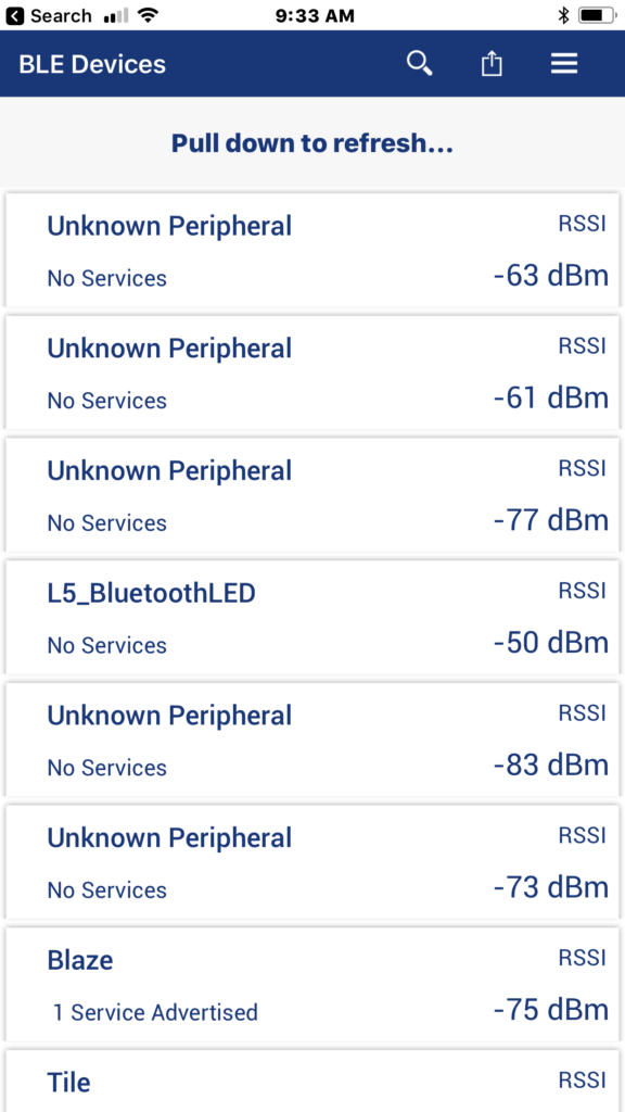
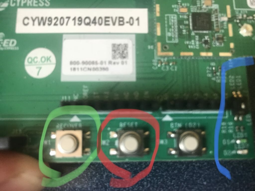
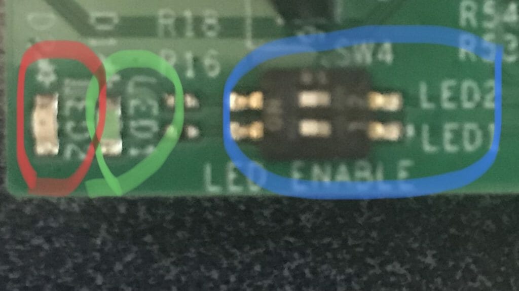
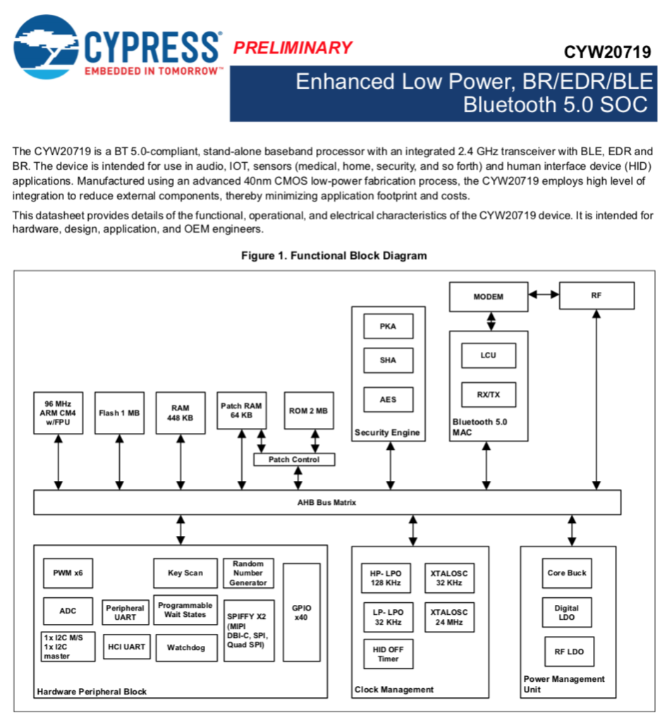
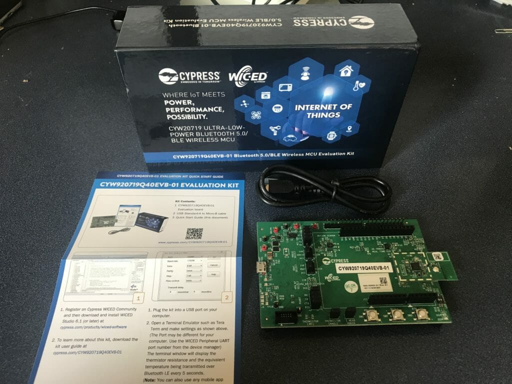
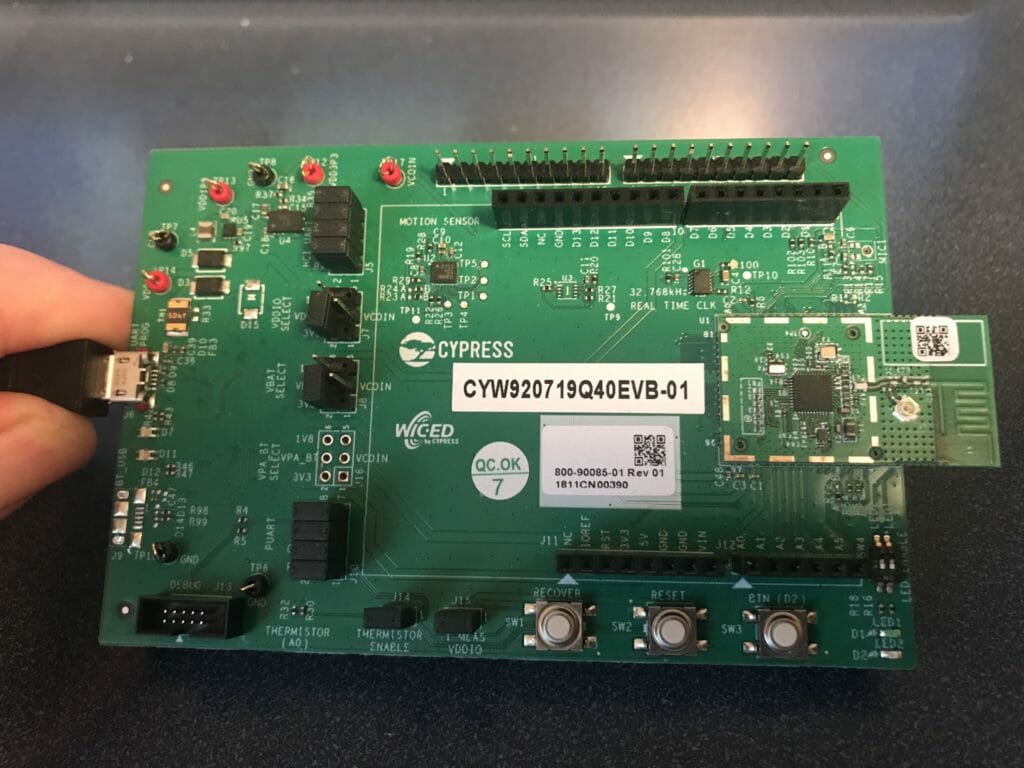
In the original article I made a connection to a PSoC4 BLE that was acting as a Peripheral with a Vendor Specific Service which I called “ledcapsense”. Then Central could then turn on/off an LED, and get notifications when the CapSense changed. In this series of articles I will make a connection to that same PSoC 4 BLE device, except that I will use a WICED CYW920719Q40EVB_01.
I will breakup this article into three parts
- Find the Peripheral, make a connection, write the GATT database to set the LED to 0 & 1
- Add the ability set the the CCCD for the CapSense Characteristic
- Perform Service Discovery
This first article will be broken up into the following steps
- Make a New Project Using Bluetooth Designer
- Remove all of the unused Advertising Code
- Add a PUART Command Line Handler
- Make the Central Scan for Peripheral Devices
- Make the Connection & Disconnect
- Write the LED Characteristic
Make a New Project Using Bluetooth Designer
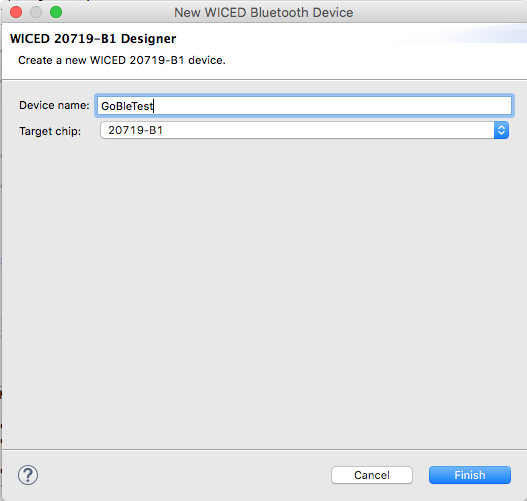
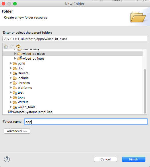
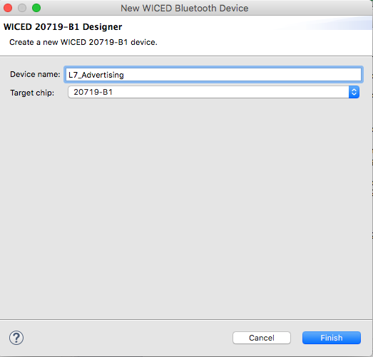
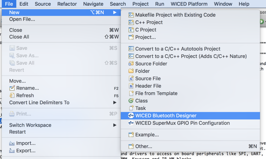
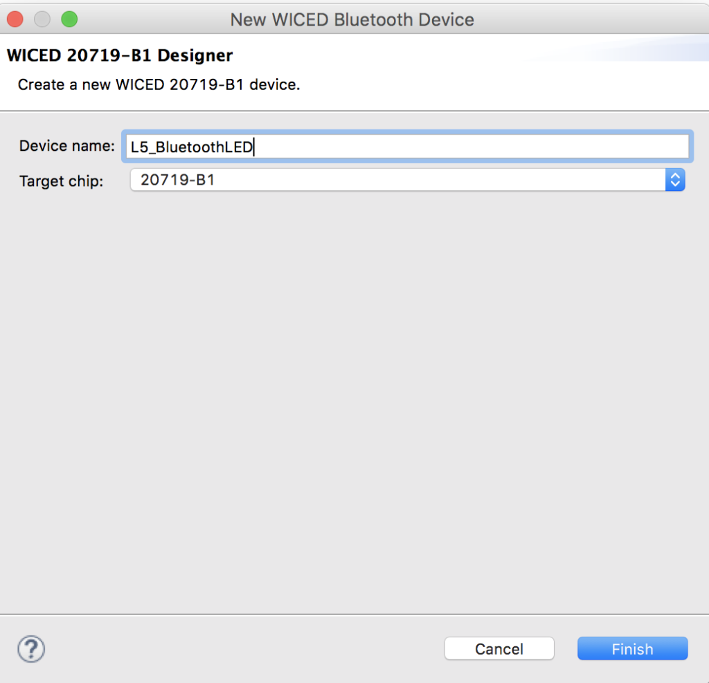
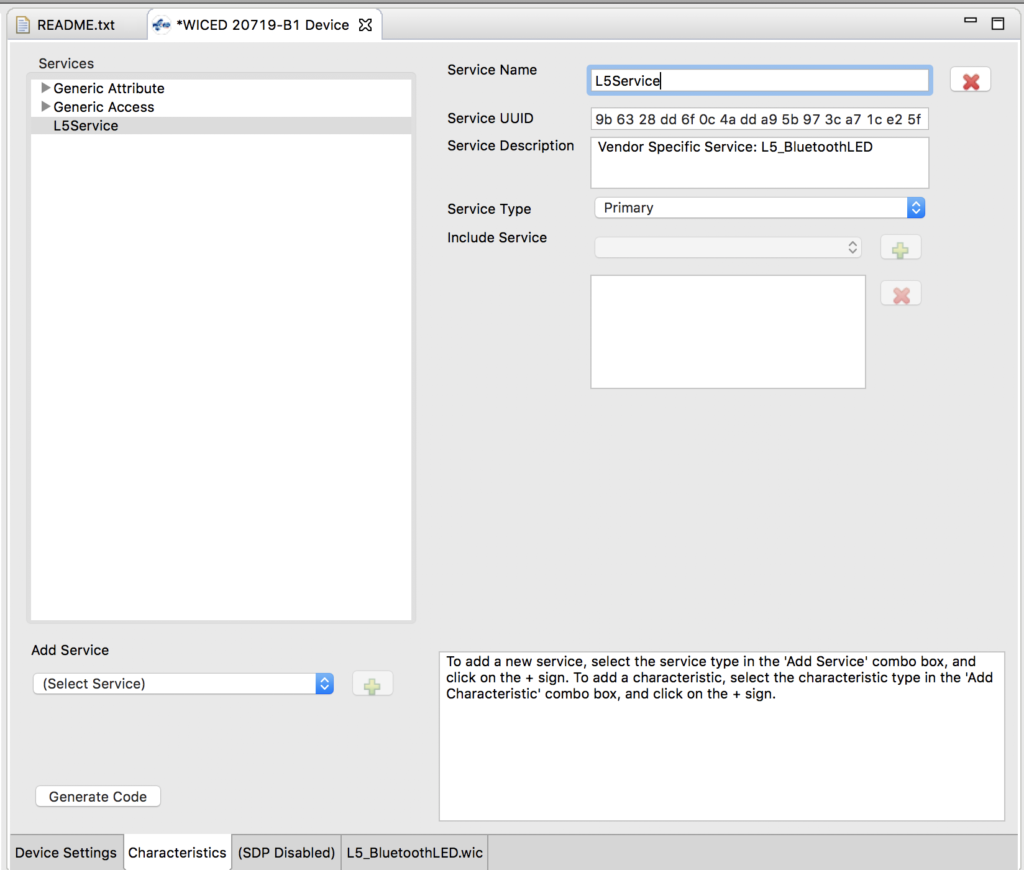
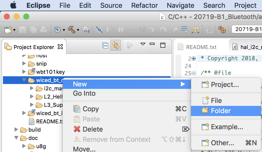
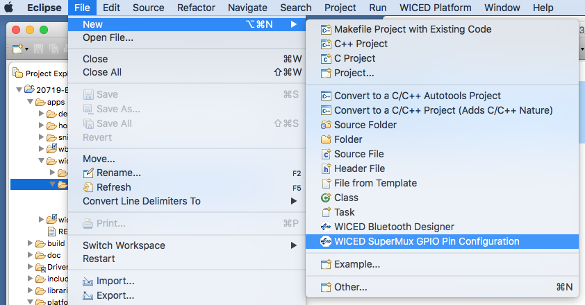
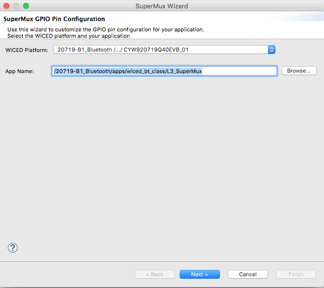
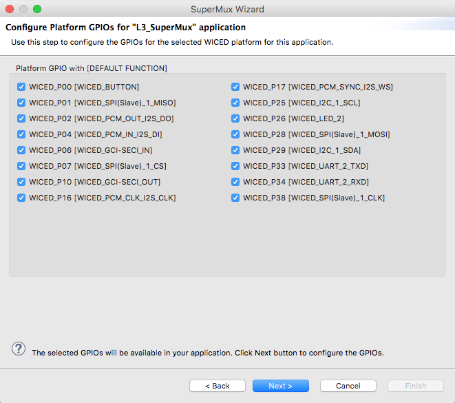
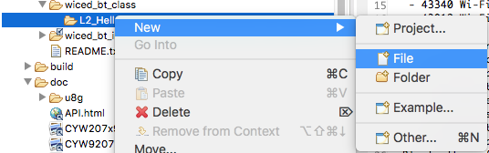
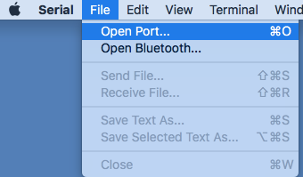
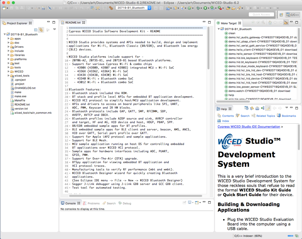
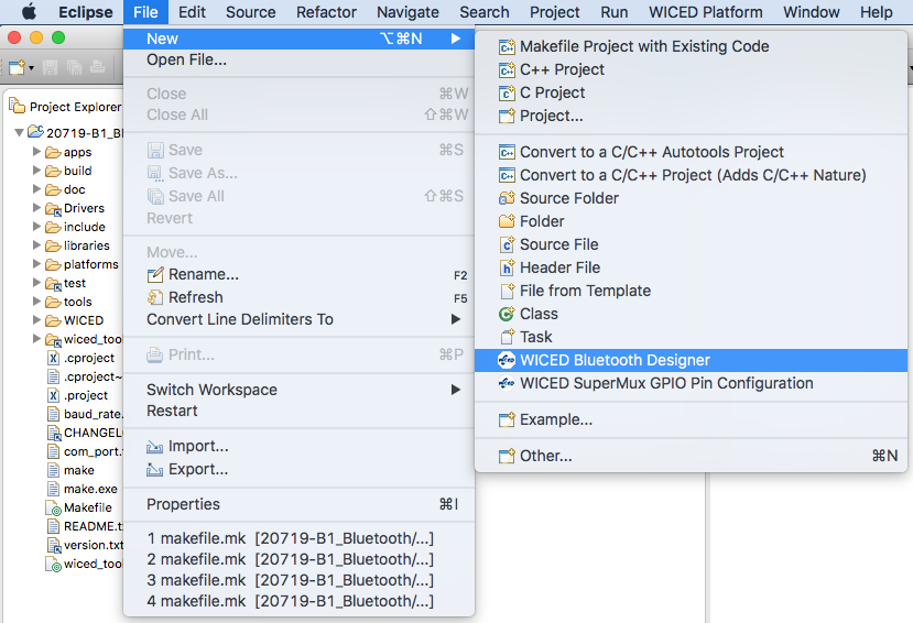
It is easiest to let the Bluetooth Designer create a template project for me. To do this, pick WICED Bluetooth Designer from the File->New menu.
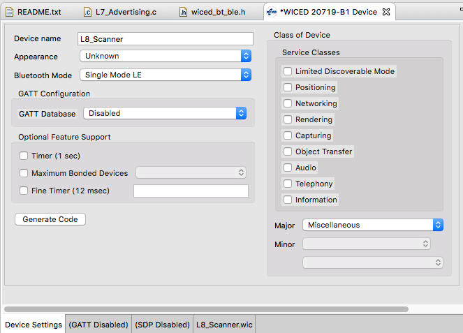
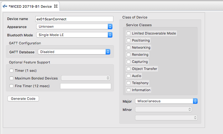
Give a project name of ex01ScanConnect and choose the 20719-B1
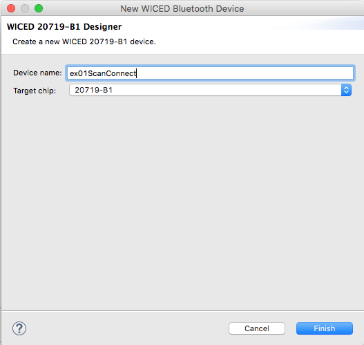
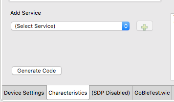
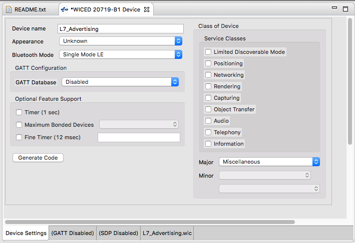
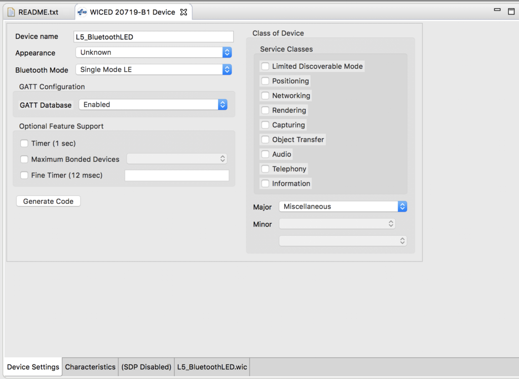
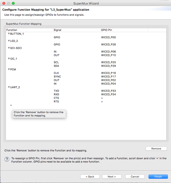
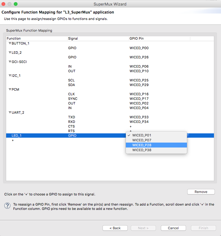
Turn off the GATT database and then press Generate Code
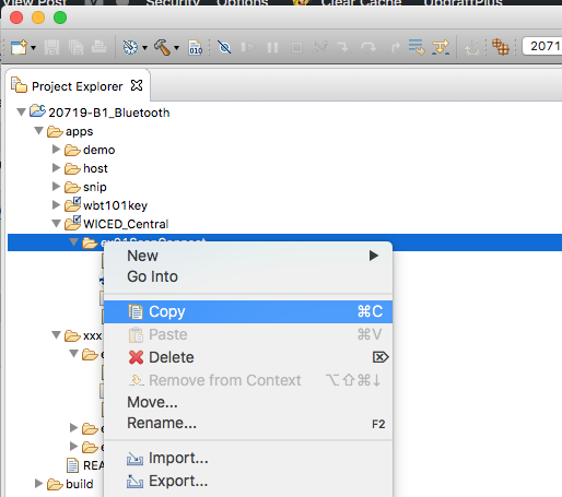
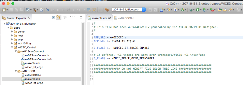
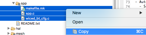
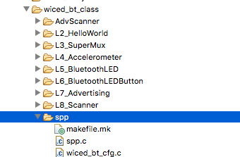
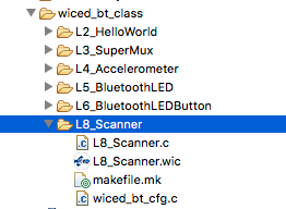
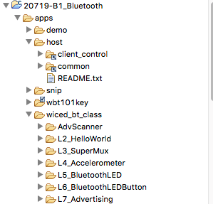
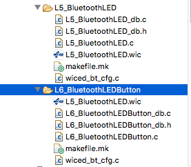
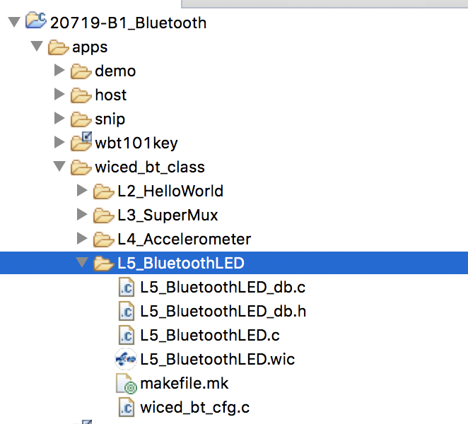
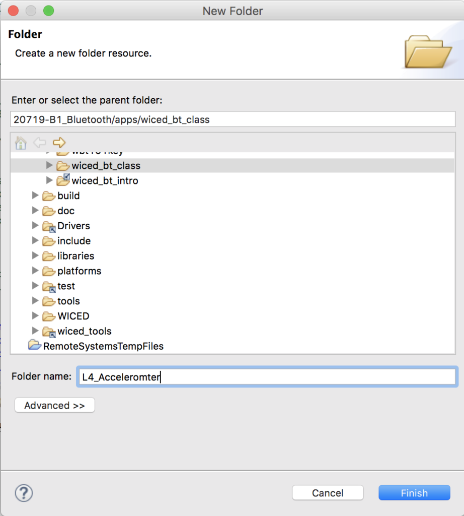
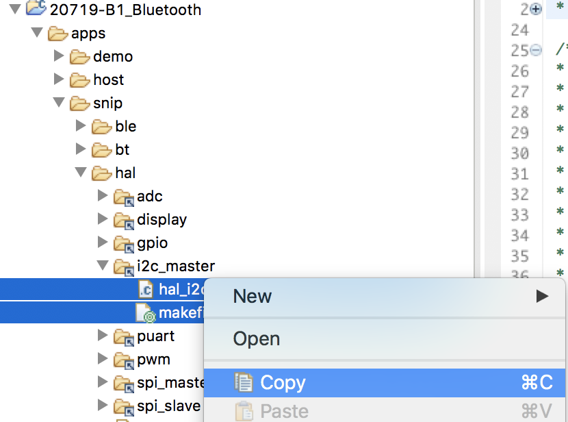
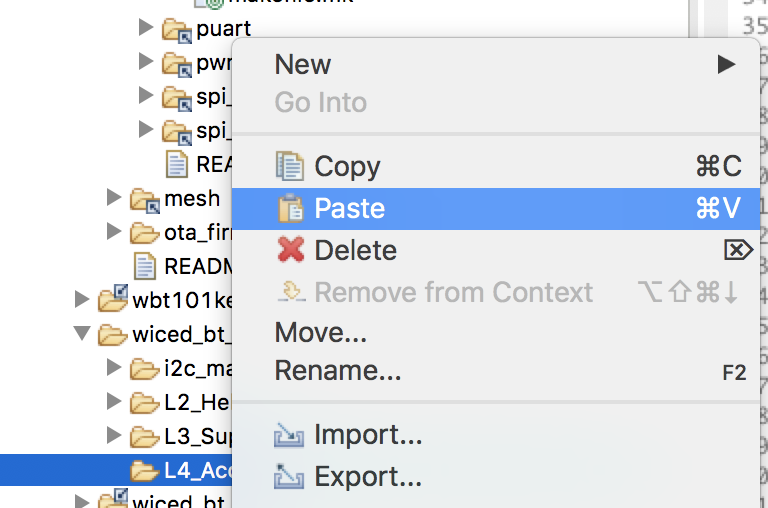
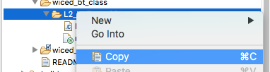
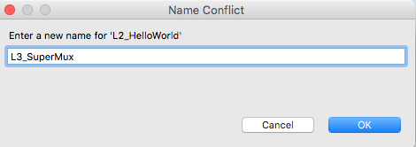
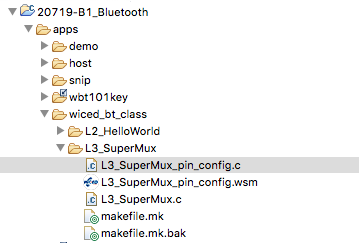
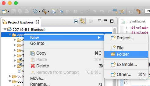
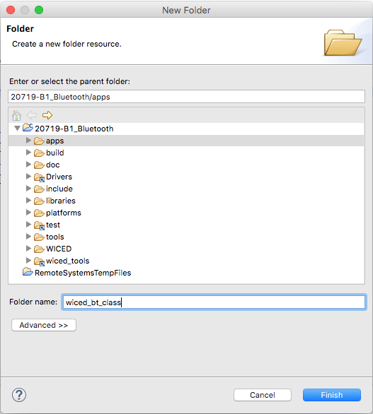
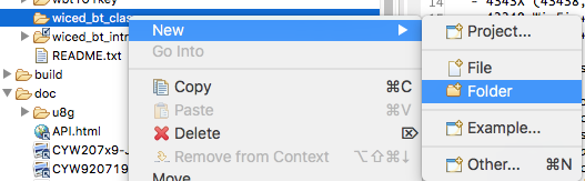
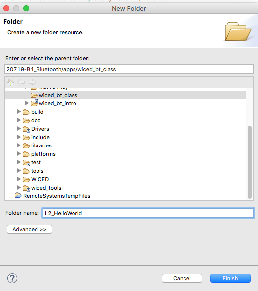
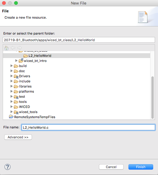
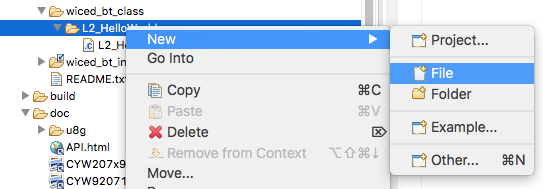
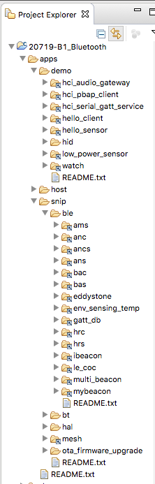
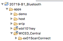
This will make a project in the top level Apps folder, but I want i to be in the WICED_Central directory, so cut and paste it.
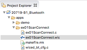
Now it looks like this:
I want to make sure the project will build, so Ill set the debug traces to go to the the PUART
#if ((defined WICED_BT_TRACE_ENABLE) || (defined HCI_TRACE_OVER_TRANSPORT))
    /* Set the Debug UART as WICED_ROUTE_DEBUG_NONE to get rid of prints */
    //  wiced_set_debug_uart( WICED_ROUTE_DEBUG_NONE );

    /* Set Debug UART as WICED_ROUTE_DEBUG_TO_PUART to see debug traces on Peripheral UART (PUART) */
      wiced_set_debug_uart( WICED_ROUTE_DEBUG_TO_PUART );

    /* Set the Debug UART as WICED_ROUTE_DEBUG_TO_WICED_UART to send debug strings over the WICED debug interface */
    //wiced_set_debug_uart( WICED_ROUTE_DEBUG_TO_WICED_UART );
#endif
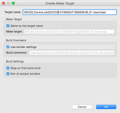
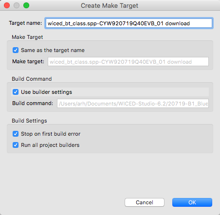
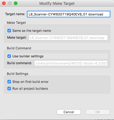
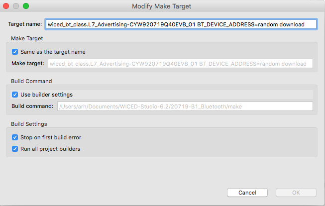
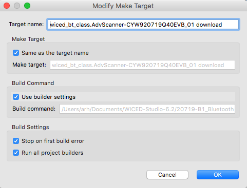
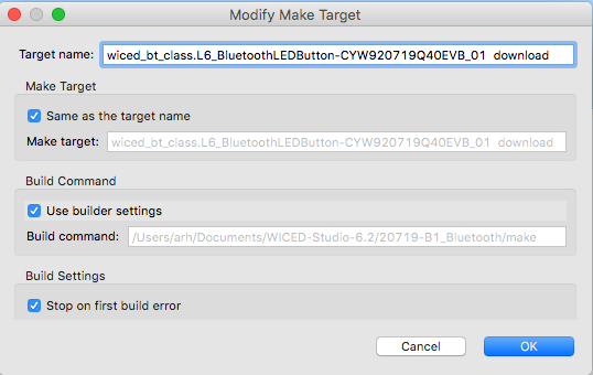
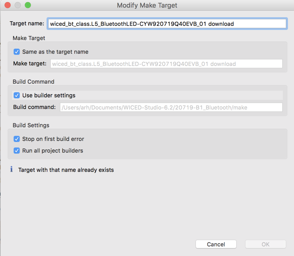
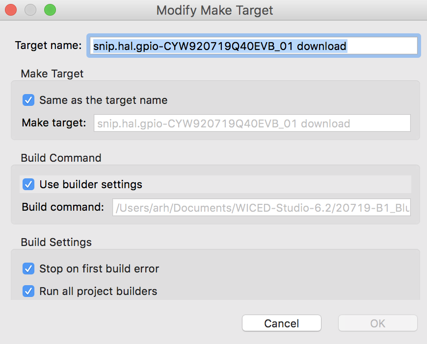
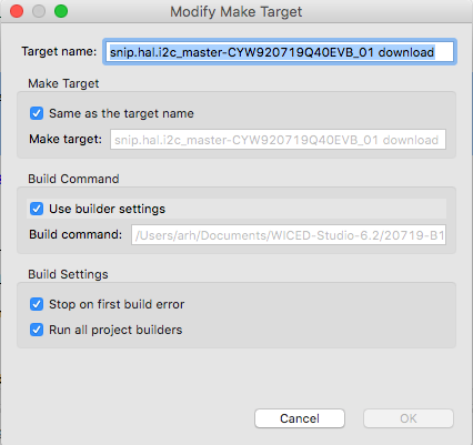
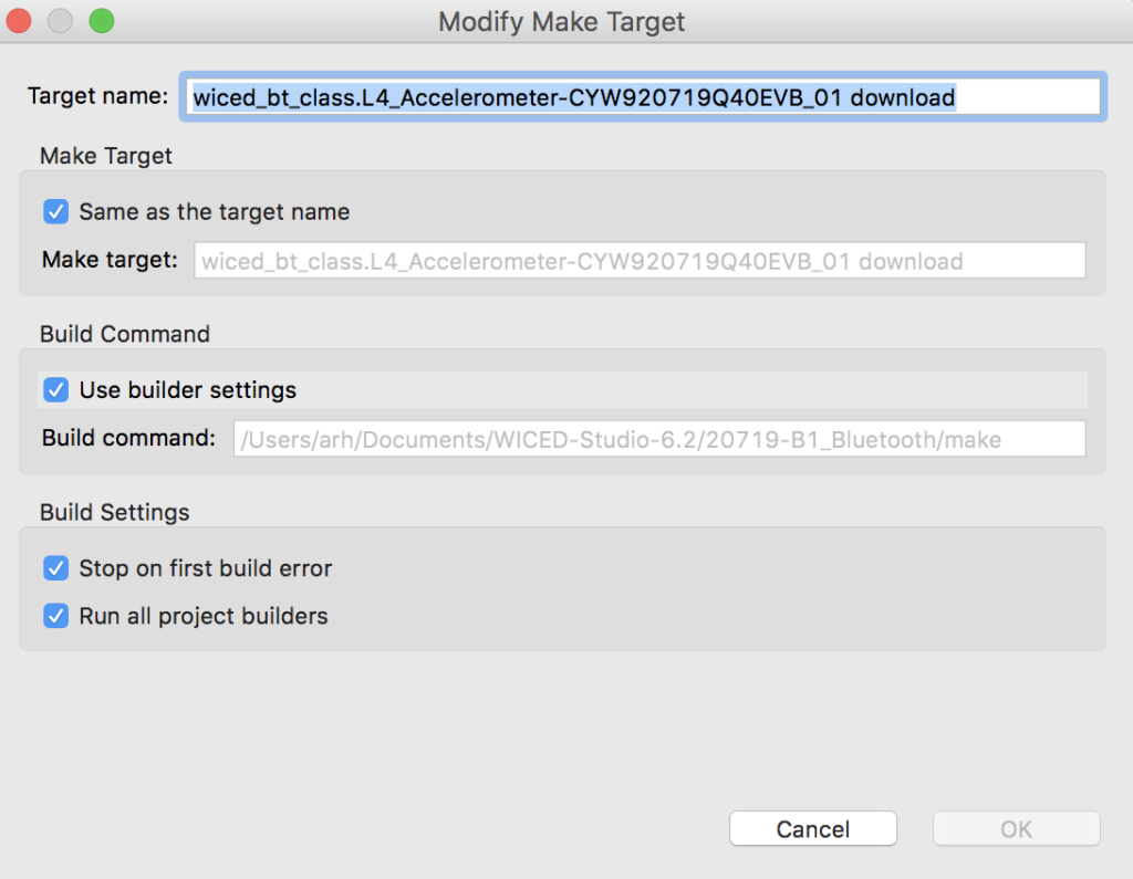
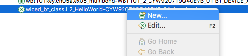
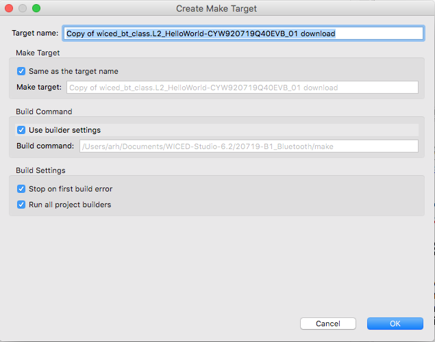
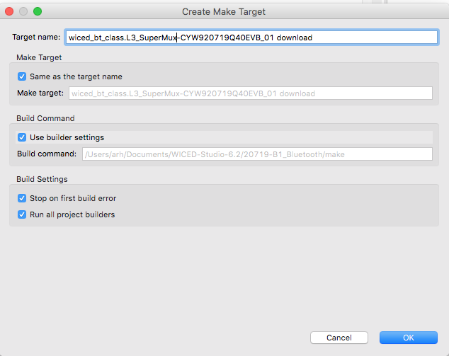
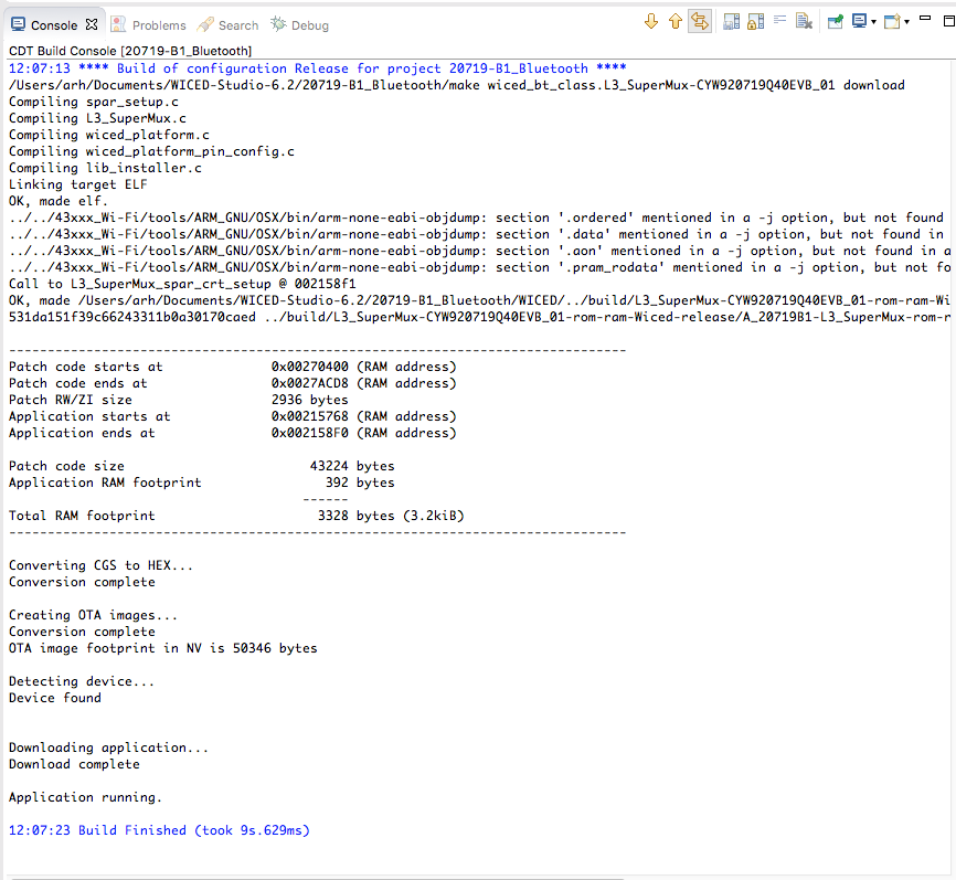
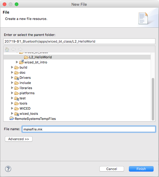
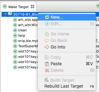
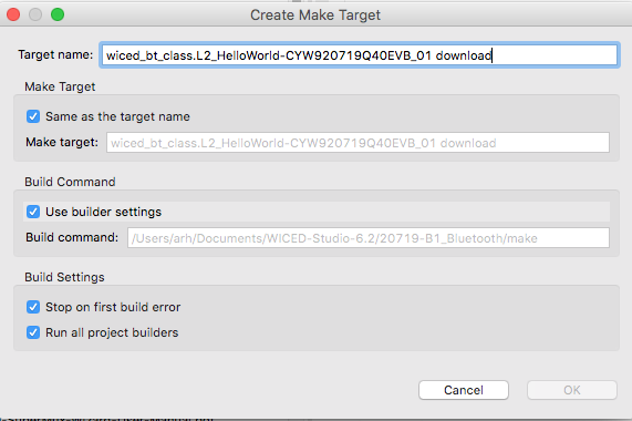
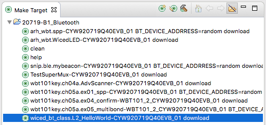
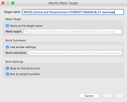
Then I create a make target for the project
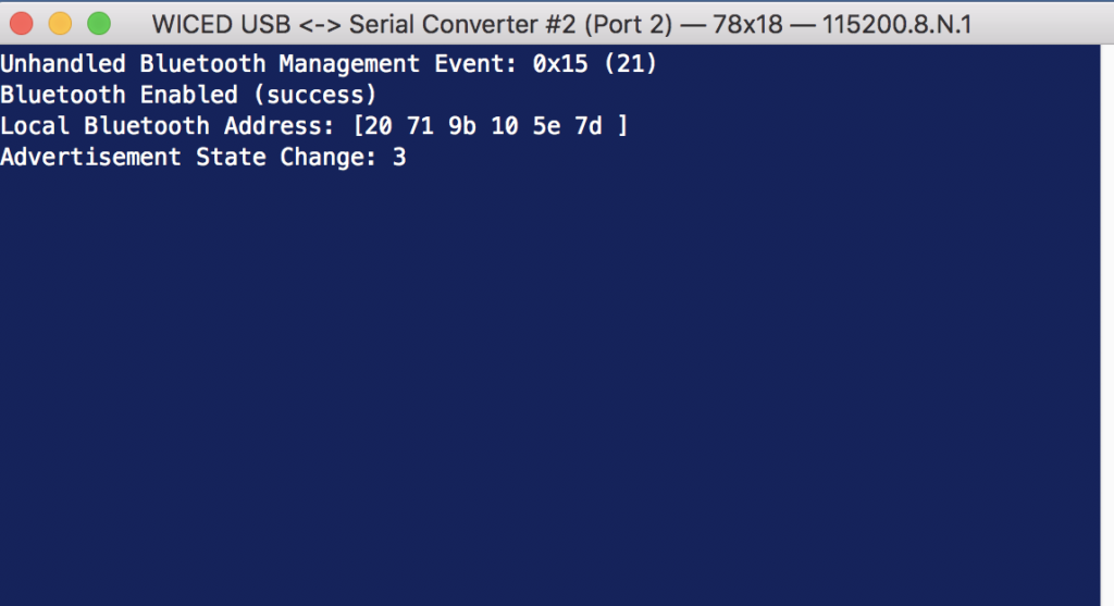
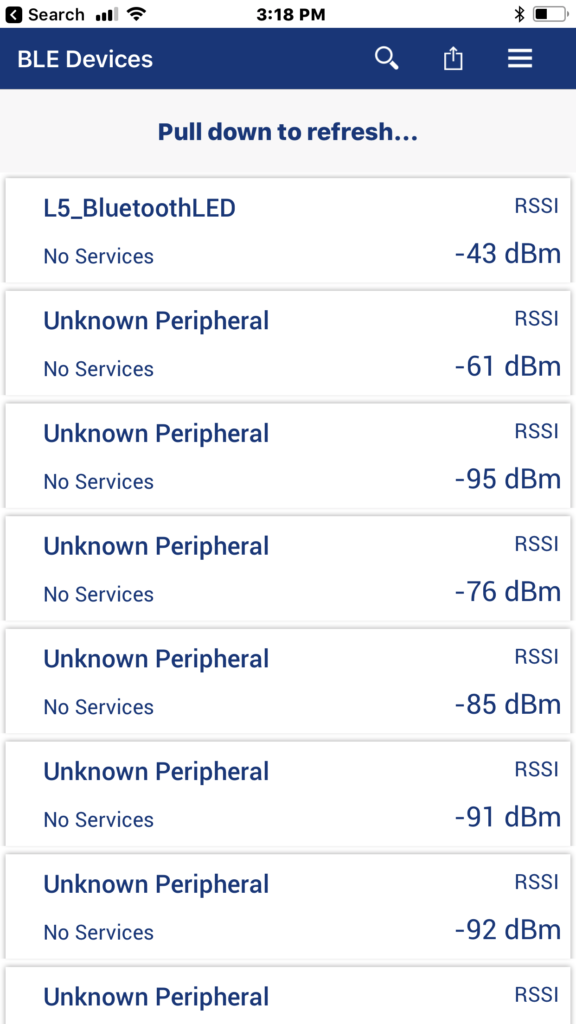
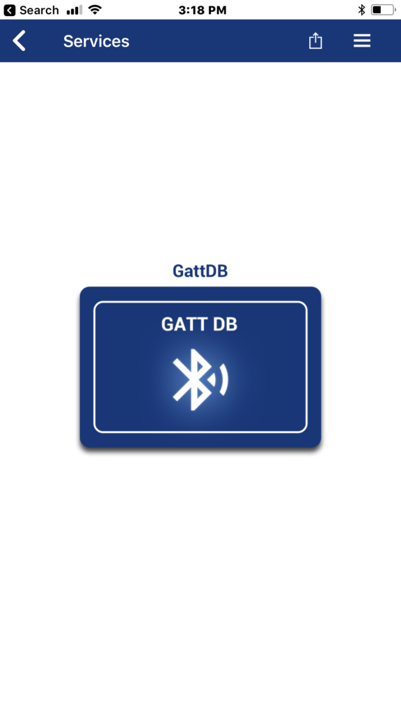
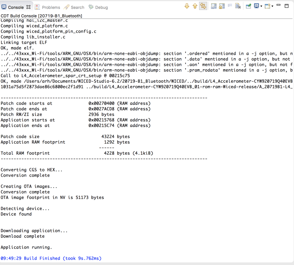
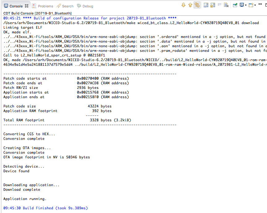
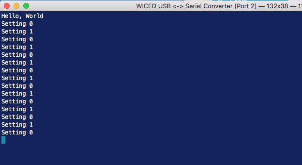
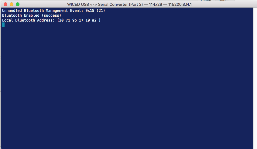
Next, lets make sure that it works.
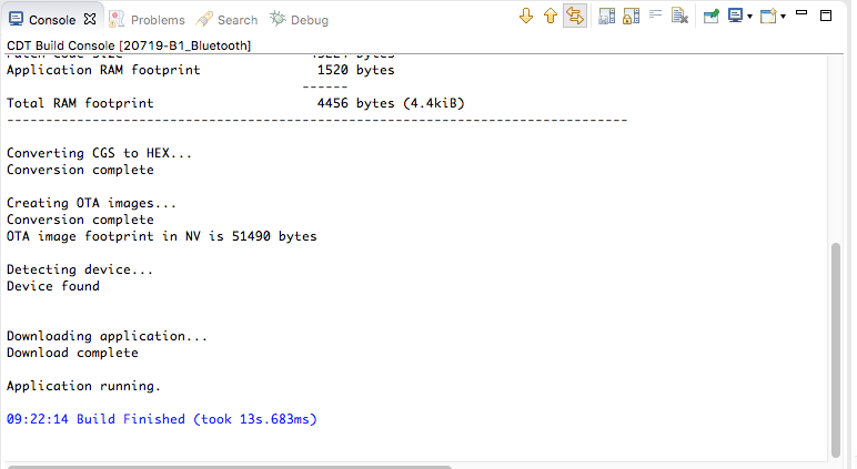
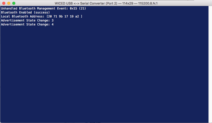
Everything seems OK… although it is advertising, which I don’t want to do. But that is easy enough to fix.
Remove all of the Advertising code
Lets get rid of all of the advertising code. First Ill remove the function prototypes for “…_set_advertisement_data” and “…_advertisement_stopped”
/*******************************************************************
 * Function Prototypes
 ******************************************************************/
static void                  ex01scanconnect_app_init               ( void );
static wiced_bt_dev_status_t ex01scanconnect_management_callback    ( wiced_bt_management_evt_t event, wiced_bt_management_evt_data_t *p_event_data );
static void                  ex01scanconnect_set_advertisement_data ( void );
static void                  ex01scanconnect_advertisement_stopped  ( void );
static void                  ex01scanconnect_reset_device           ( void );
static uint32_t              hci_control_process_rx_cmd             ( uint8_t* p_data, uint32_t len );
#ifdef HCI_TRACE_OVER_TRANSPORT
static void                  ex01scanconnect_trace_callback         ( wiced_bt_hci_trace_type_t type, uint16_t length, uint8_t* p_data );
#endif
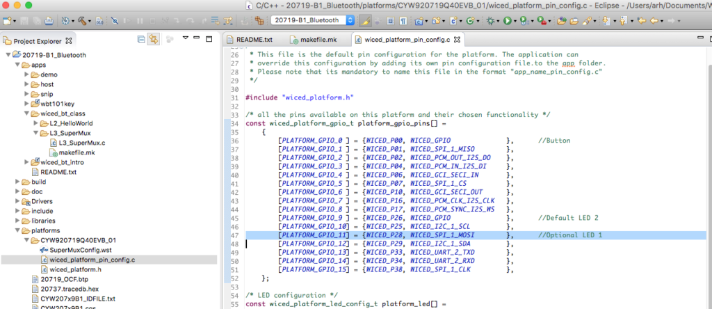
Then Ill delete everything from “…set_pairable_mode” on line 128 down through the two functions ending on line 169
    /* Allow peer to pair */
    wiced_bt_set_pairable_mode(WICED_TRUE, 0);

    /* Set Advertisement Data */
    ex01scanconnect_set_advertisement_data();

    /* Start Undirected LE Advertisements on device startup.
     * The corresponding parameters are contained in 'wiced_bt_cfg.c' */
    /* TODO: Make sure that this is the desired behavior. */
    wiced_bt_start_advertisements(BTM_BLE_ADVERT_UNDIRECTED_HIGH, 0, NULL);
}

/* Set Advertisement Data */
void ex01scanconnect_set_advertisement_data( void )
{
    wiced_bt_ble_advert_elem_t adv_elem[2] = { 0 };
    uint8_t adv_flag = BTM_BLE_GENERAL_DISCOVERABLE_FLAG | BTM_BLE_BREDR_NOT_SUPPORTED;
    uint8_t num_elem = 0;

    /* Advertisement Element for Flags */
    adv_elem[num_elem].advert_type = BTM_BLE_ADVERT_TYPE_FLAG;
    adv_elem[num_elem].len = sizeof(uint8_t);
    adv_elem[num_elem].p_data = &adv_flag;
    num_elem++;

    /* Advertisement Element for Name */
    adv_elem[num_elem].advert_type = BTM_BLE_ADVERT_TYPE_NAME_COMPLETE;
    adv_elem[num_elem].len = strlen((const char*)BT_LOCAL_NAME);
    adv_elem[num_elem].p_data = BT_LOCAL_NAME;
    num_elem++;

    /* Set Raw Advertisement Data */
    wiced_bt_ble_set_raw_advertisement_data(num_elem, adv_elem);
}

/* This function is invoked when advertisements stop */
void ex01scanconnect_advertisement_stopped( void )
{
    WICED_BT_TRACE("Advertisement stopped\n");

    /* TODO: Handle when advertisements stop */
}
In the Bluetooth Management Callback function you dont need the local variable p_adv_mode (line 145) so delete it.
/* Bluetooth Management Event Handler */
wiced_bt_dev_status_t ex01scanconnect_management_callback( wiced_bt_management_evt_t event, wiced_bt_management_evt_data_t *p_event_data )
{
    wiced_bt_dev_status_t status = WICED_BT_SUCCESS;
    wiced_bt_device_address_t bda = { 0 };
    wiced_bt_dev_ble_pairing_info_t *p_ble_info = NULL;
    wiced_bt_ble_advert_mode_t *p_adv_mode = NULL;
And, because you are not advertising, you don’t need to handle that callback so delete this block of code.
    case BTM_BLE_ADVERT_STATE_CHANGED_EVT:
        /* Advertisement State Changed */
        p_adv_mode = &p_event_data->ble_advert_state_changed;
        WICED_BT_TRACE("Advertisement State Change: %d\n", *p_adv_mode);
        if ( BTM_BLE_ADVERT_OFF == *p_adv_mode )
        {
            ex01scanconnect_advertisement_stopped();
        }
        break;
Now run the make target again to make sure you didn’t break anything.
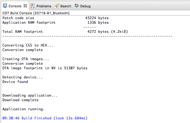
After programming, things still seem to work.
Add PUART Command Line Handler
In this project I am going to make keyboard commands to do the different things. In order to make all of that work, Ill include the HAL for the PUART.
#include "wiced_hal_puart.h"
Then Ill add a function prototype for the callback for the receive data handler (line 59)
/*******************************************************************
 * Function Prototypes
 ******************************************************************/
static void                  ex01scanconnect_app_init               ( void );
static wiced_bt_dev_status_t ex01scanconnect_management_callback    ( wiced_bt_management_evt_t event, wiced_bt_management_evt_data_t *p_event_data );
static uint32_t              hci_control_process_rx_cmd             ( uint8_t* p_data, uint32_t len );
#ifdef HCI_TRACE_OVER_TRANSPORT
static void                  ex01scanconnect_trace_callback         ( wiced_bt_hci_trace_type_t type, uint16_t length, uint8_t* p_data );
#endif

static void rx_cback( void *data )
In the application init function Ill initialize the PUART and setup a callback for keys from the serial port.
void ex01scanconnect_app_init(void)
{
/* Initialize Application */
wiced_bt_app_init();
/* Initialize the UART for input */
wiced_hal_puart_init( );
wiced_hal_puart_flow_off( );
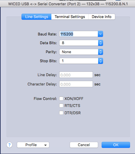
wiced_hal_puart_set_baudrate( 115200 );
/* Enable receive and the interrupt */
wiced_hal_puart_register_interrupt( rx_cback );
/* Set watermark level to 1 to receive interrupt up on receiving each byte */
wiced_hal_puart_set_watermark_level( 1 );
wiced_hal_puart_enable_rx();
}
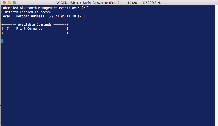
And create a new function called “rx_cback” which will be called when a key is pressed. In this case the only key to process is ‘?’ which will print out the help.
void rx_cback( void *data )
{
    uint8_t  readbyte;
    uint32_t focus;

    /* Read one byte from the buffer and (unlike GPIO) reset the interrupt */
    wiced_hal_puart_read( &readbyte );
    wiced_hal_puart_reset_puart_interrupt();

    switch (readbyte)
    {


    case '?':
        /* Print help */
        WICED_BT_TRACE( "\n" );
        WICED_BT_TRACE( "+------- Available Commands -------+\n" );
        WICED_BT_TRACE( "|  ?    Print Commands             |\n" );
        WICED_BT_TRACE( "+----------------------------------+\n" );
        WICED_BT_TRACE( "\n" );
        break;
    }
}
Program it again and make sure that the ‘?’ works
Make the Central Scan for Peripheral Devices
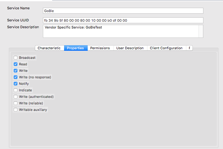
You might recall that the PSoC 4 CapSense BLE Peripheral is advertising a “Service UUID” that is my custom service. Here is a picture of the advertising packet customizer from PSoC Creator.
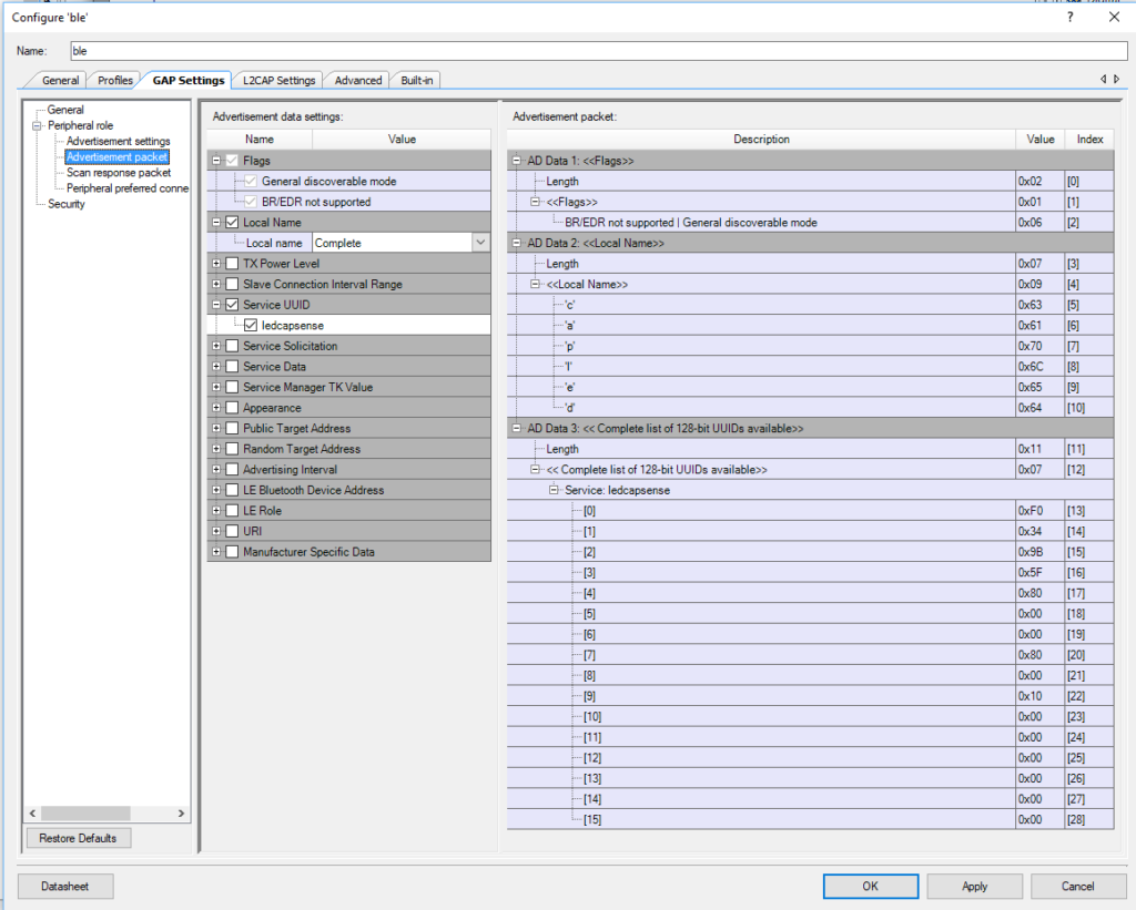
If you look in the PSoC Creator project in the Generated Source file ble_gatt.c you will find C-Declarations of the UUIDs for the ledcapsense service, the led characteristic and the capsense characteristic.
const uint8 cyBle_attUuid128[][16u] = {
    /* ledcapsense */
    { 0xF0u, 0x34u, 0x9Bu, 0x5Fu, 0x80u, 0x00u, 0x00u, 0x80u, 0x00u, 0x10u, 0x00u, 0x00u, 0x00u, 0x00u, 0x00u, 0x00u },
    /* led */
    { 0xF1u, 0x34u, 0x9Bu, 0x5Fu, 0x80u, 0x00u, 0x00u, 0x80u, 0x00u, 0x10u, 0x00u, 0x00u, 0x00u, 0x00u, 0x00u, 0x00u },
    /* capsense */
    { 0xF2u, 0x34u, 0x9Bu, 0x5Fu, 0x80u, 0x00u, 0x00u, 0x80u, 0x00u, 0x10u, 0x00u, 0x00u, 0x00u, 0x00u, 0x00u, 0x00u },
};
I copy that byte array for ledcapsense into my project so that I can match against it.
static const uint8_t matchServiceUUID[] = {0xF0 ,0x34 ,0x9B ,0x5F ,0x80 ,0x00 ,0x00 ,0x80 ,0x00 ,0x10 ,0x00 ,0x00 ,0x00 ,0x00 ,0x00 ,0x00 };
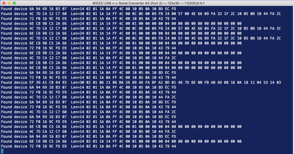
The way that the WICED scanner works is that it will give you a callback every time it hears a Peripheral advertisement packet. It passes you the pointer to some information about what device it heard (p_scan_result), as well as the raw bytes of the advertising packet (p_adv_data). WICED has a function called “wiced_bt_ble_check_advertising_data” which will search through the raw advertising data looking for a field of the type you specify. If found, the function will return a pointer to the raw data. In this case I’m looking for a field of type “BTM_BLE_ADVERT_TYPE_128SRV_COMPLETE”, in other words, a device that is advertising that it has a 128-uuid service as available on that device.
All this function does is, if I find that field in the advertising packet and the service UUID matches the capsenseled UUID, then I print out that I found it.
// This function is called when an advertising packet is received.
void newAdvCallback(wiced_bt_ble_scan_results_t *p_scan_result, uint8_t *p_adv_data)
{

    uint8_t length;

    uint8_t *serviceUUID = wiced_bt_ble_check_advertising_data(p_adv_data,BTM_BLE_ADVERT_TYPE_128SRV_COMPLETE,&length);
    if(serviceUUID && memcmp(serviceUUID,matchServiceUUID,16) == 0)
    {
        WICED_BT_TRACE("Host = %B Found Service UUID\r\n ",p_scan_result->remote_bd_addr);

    }

}
At the bottom of the project, Ill add ‘s’ to start scanning and ‘S’ to stop scanning.
    switch (readbyte)
    {

    case 's':
        WICED_BT_TRACE( "Scan On\r\n" );
        wiced_bt_ble_scan(BTM_BLE_SCAN_TYPE_HIGH_DUTY,FALSE,newAdvCallback);
        break;
    case 'S':
        WICED_BT_TRACE( "Scan Off\r\n" );
        wiced_bt_ble_scan(BTM_BLE_SCAN_TYPE_NONE,FALSE,newAdvCallback);
        break;
And don’t forget to update the help.
        WICED_BT_TRACE( "|  s    Turn on Scanning           |\n" );
        WICED_BT_TRACE( "|  S    Turn off Scanning          |\n" );
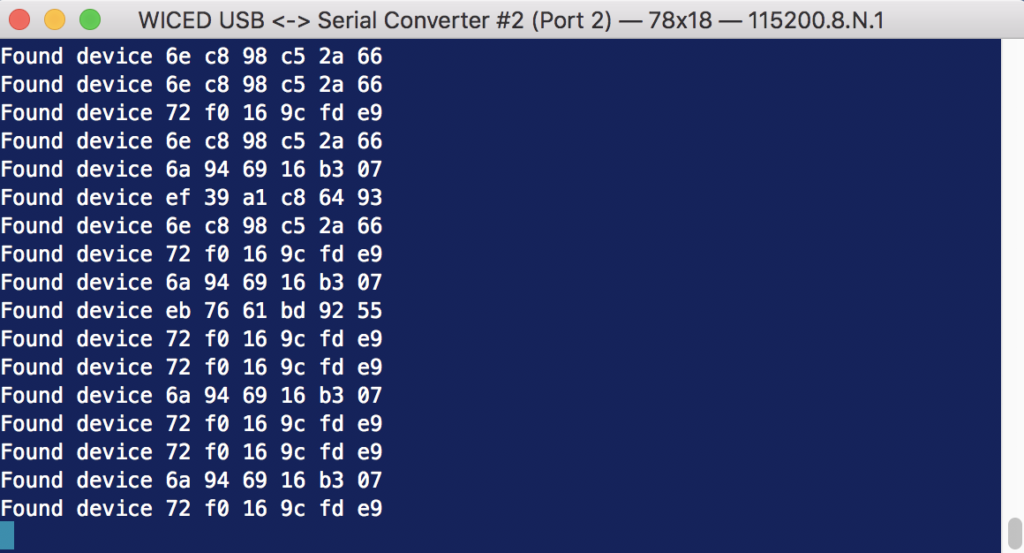
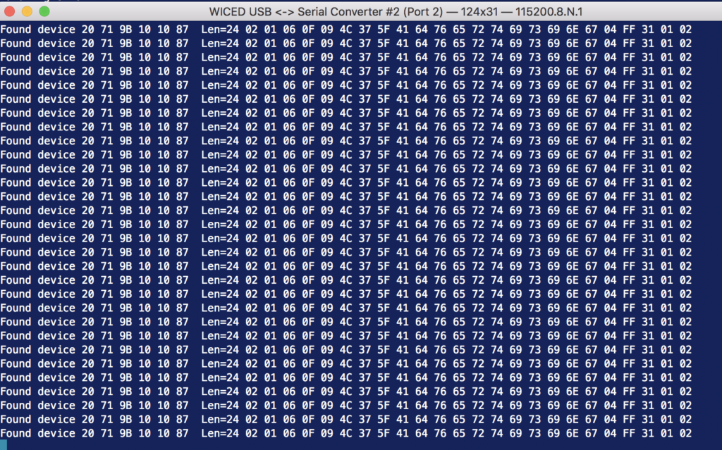
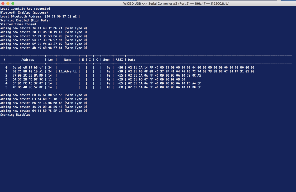
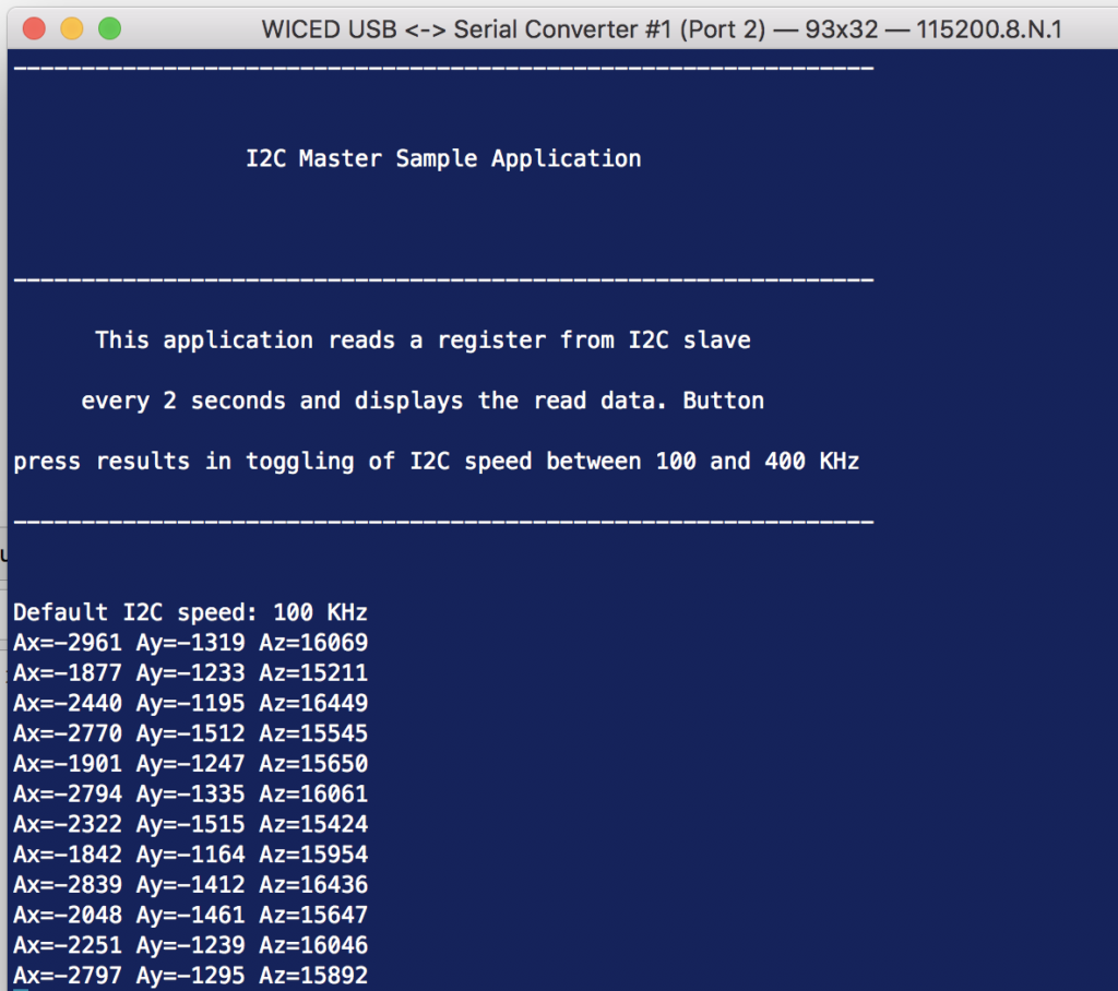
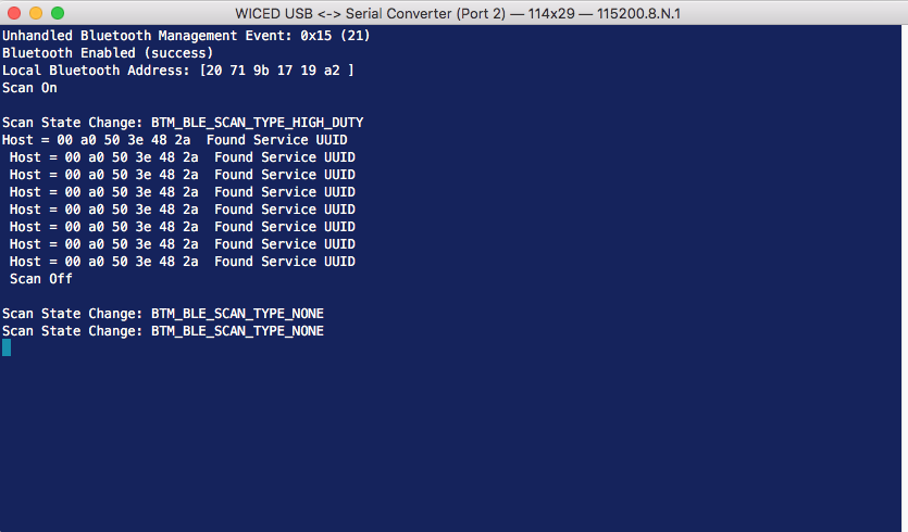
When I run the make target everything appears to be working. First I press ‘?’ and the help is correct. Then I press ‘s’ to start scanning. It immediately (and repeatedly) finds my device.
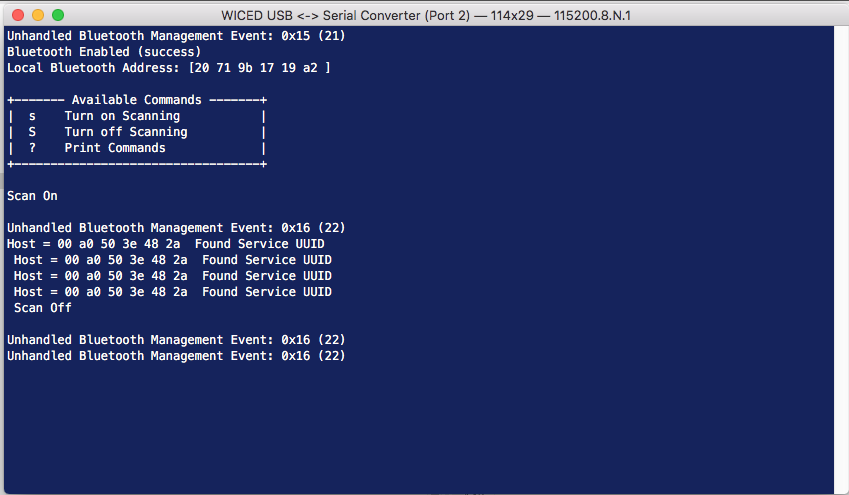
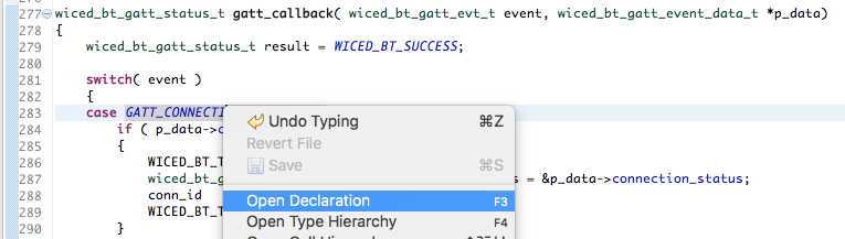
What is the unhandled Bluetooth Management Event: 0x16 (22)? You can find the answer to that question by right clicking on the wiced_bt_management_event_t and “Open Declaration”
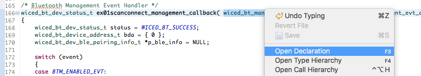
That will take you to the “wiced_bt_dev.h” file in this enumeration. On line 683 you will see the “BTM_BLE_SCAN_STATE_CHANGED_EVT” which you are getting a callback every time the scan state changes.
enum wiced_bt_management_evt_e {
    /* Bluetooth status events */
    BTM_ENABLED_EVT,                                /**< Bluetooth controller and host stack enabled. Event data: wiced_bt_dev_enabled_t */
    BTM_DISABLED_EVT,                               /**< Bluetooth controller and host stack disabled. Event data: NULL */
    BTM_POWER_MANAGEMENT_STATUS_EVT,                /**< Power management status change. Event data: wiced_bt_power_mgmt_notification_t */
#ifdef WICED_X
    BTM_RE_START_EVT,                             /**< Bluetooth controller and host stack re-enabled. Event data: tBTM_ENABLED_EVT */
#endif
    /* Security events */
    BTM_PIN_REQUEST_EVT,                            /**< PIN request (used only with legacy devices). Event data: #wiced_bt_dev_name_and_class_t */
    BTM_USER_CONFIRMATION_REQUEST_EVT,              /**< received USER_CONFIRMATION_REQUEST event (respond using #wiced_bt_dev_confirm_req_reply). Event data: #wiced_bt_dev_user_cfm_req_t */
    BTM_PASSKEY_NOTIFICATION_EVT,                   /**< received USER_PASSKEY_NOTIFY event. Event data: #wiced_bt_dev_user_key_notif_t */
    BTM_PASSKEY_REQUEST_EVT,                        /**< received USER_PASSKEY_REQUEST event (respond using #wiced_bt_dev_pass_key_req_reply). Event data: #wiced_bt_dev_user_key_req_t */
    BTM_KEYPRESS_NOTIFICATION_EVT,                  /**< received KEYPRESS_NOTIFY event. Event data: #wiced_bt_dev_user_keypress_t */
    BTM_PAIRING_IO_CAPABILITIES_BR_EDR_REQUEST_EVT, /**< Requesting IO capabilities for BR/EDR pairing. Event data: #wiced_bt_dev_bredr_io_caps_req_t */
    BTM_PAIRING_IO_CAPABILITIES_BR_EDR_RESPONSE_EVT,/**< Received IO capabilities response for BR/EDR pairing. Event data: #wiced_bt_dev_bredr_io_caps_rsp_t */
    BTM_PAIRING_IO_CAPABILITIES_BLE_REQUEST_EVT,    /**< Requesting IO capabilities for BLE pairing. Slave can check peer io capabilities in event data before updating with local io capabilities. Event data: #wiced_bt_dev_ble_io_caps_req_t */
    BTM_PAIRING_COMPLETE_EVT,                       /**< received SIMPLE_PAIRING_COMPLETE event. Event data: #wiced_bt_dev_pairing_cplt_t */
    BTM_ENCRYPTION_STATUS_EVT,                      /**< Encryption status change. Event data: #wiced_bt_dev_encryption_status_t */
    BTM_SECURITY_REQUEST_EVT,                       /**< Security request (respond using #wiced_bt_ble_security_grant). Event data: #wiced_bt_dev_security_request_t */
    BTM_SECURITY_FAILED_EVT,                        /**< Security procedure/authentication failed. Event data: #wiced_bt_dev_security_failed_t */
    BTM_SECURITY_ABORTED_EVT,                       /**< Security procedure aborted locally, or unexpected link drop. Event data: #wiced_bt_dev_name_and_class_t */

    BTM_READ_LOCAL_OOB_DATA_COMPLETE_EVT,           /**< Result of reading local OOB data (wiced_bt_dev_read_local_oob_data). Event data: #wiced_bt_dev_local_oob_t */
    BTM_REMOTE_OOB_DATA_REQUEST_EVT,                /**< OOB data from remote device (respond using #wiced_bt_dev_remote_oob_data_reply). Event data: #wiced_bt_dev_remote_oob_t */

    BTM_PAIRED_DEVICE_LINK_KEYS_UPDATE_EVT,         /**< Updated remote device link keys (store device_link_keys to  NV memory). This is the place to
verify that the correct link key has been generated. Event data: #wiced_bt_device_link_keys_t */
    BTM_PAIRED_DEVICE_LINK_KEYS_REQUEST_EVT,        /**< Request for stored remote device link keys (restore device_link_keys from NV memory). If successful, return WICED_BT_SUCCESS. Event data: #wiced_bt_device_link_keys_t */

    BTM_LOCAL_IDENTITY_KEYS_UPDATE_EVT,             /**< Update local identity key (stored local_identity_keys NV memory). Event data: #wiced_bt_local_identity_keys_t */
    BTM_LOCAL_IDENTITY_KEYS_REQUEST_EVT,            /**< Request local identity key (get local_identity_keys from NV memory). If successful, return WICED_BT_SUCCESS. Event data: #wiced_bt_local_identity_keys_t */

    BTM_BLE_SCAN_STATE_CHANGED_EVT,                 /**< BLE scan state change. Event data: #wiced_bt_ble_scan_type_t */
    BTM_BLE_ADVERT_STATE_CHANGED_EVT,               /**< BLE advertisement state change. Event data: #wiced_bt_ble_advert_mode_t */

    /* BLE Secure Connection events */
    BTM_SMP_REMOTE_OOB_DATA_REQUEST_EVT,            /**< SMP remote oob data request. Reply using wiced_bt_smp_oob_data_reply. Event data: wiced_bt_smp_remote_oob_req_t  */
    BTM_SMP_SC_REMOTE_OOB_DATA_REQUEST_EVT,         /**< LE secure connection remote oob data request. Reply using wiced_bt_smp_sc_oob_reply. Event data: #wiced_bt_smp_sc_remote_oob_req_t */
    BTM_SMP_SC_LOCAL_OOB_DATA_NOTIFICATION_EVT,     /**< LE secure connection local OOB data (wiced_bt_smp_create_local_sc_oob_data). Event data: #wiced_bt_smp_sc_local_oob_t*/

    BTM_SCO_CONNECTED_EVT,                          /**< SCO connected event. Event data: #wiced_bt_sco_connected_t */
    BTM_SCO_DISCONNECTED_EVT,                       /**< SCO disconnected event. Event data: #wiced_bt_sco_disconnected_t */
    BTM_SCO_CONNECTION_REQUEST_EVT,                 /**< SCO connection request event. Event data: #wiced_bt_sco_connection_request_t */
    BTM_SCO_CONNECTION_CHANGE_EVT,					/**< SCO connection change event. Event data: #wiced_bt_sco_connection_change_t */
    BTM_BLE_CONNECTION_PARAM_UPDATE                 /**< BLE connection parameter update. Event data: #wiced_bt_ble_connection_param_update_t */

};
#endif
typedef uint8_t wiced_bt_management_evt_t;          /**< Bluetooth management events (see #wiced_bt_management_evt_e) */
You notice that the event parameter is of type “wiced_bt_ble_scan_type_t”. When I right click, I find its definition is this:
enum wiced_bt_ble_scan_type_e
{
    BTM_BLE_SCAN_TYPE_NONE,         /**< Stop scanning */
    BTM_BLE_SCAN_TYPE_HIGH_DUTY,    /**< High duty cycle scan */
    BTM_BLE_SCAN_TYPE_LOW_DUTY      /**< Low duty cycle scan */
};
Now I can add a case to the Bluetooth Management callback to handle the case “BTM_BLE_SCAN_STATE_CHANGED_EVT”. All it does it look at the parameter and print it out.
    case BTM_BLE_SCAN_STATE_CHANGED_EVT:
        WICED_BT_TRACE("Scan State Change: ");
        if(p_event_data->ble_scan_state_changed == BTM_BLE_SCAN_TYPE_NONE)
            WICED_BT_TRACE("BTM_BLE_SCAN_TYPE_NONE\n");
        else if (p_event_data->ble_scan_state_changed == BTM_BLE_SCAN_TYPE_HIGH_DUTY)
            WICED_BT_TRACE("BTM_BLE_SCAN_TYPE_HIGH_DUTY\n");
        else if(p_event_data->ble_scan_state_changed == BTM_BLE_SCAN_TYPE_LOW_DUTY)
            WICED_BT_TRACE("BTM_BLE_SCAN_TYPE_LOW_DUTY\n");
        else
            WICED_BT_TRACE("Unknkown\n");
        break;
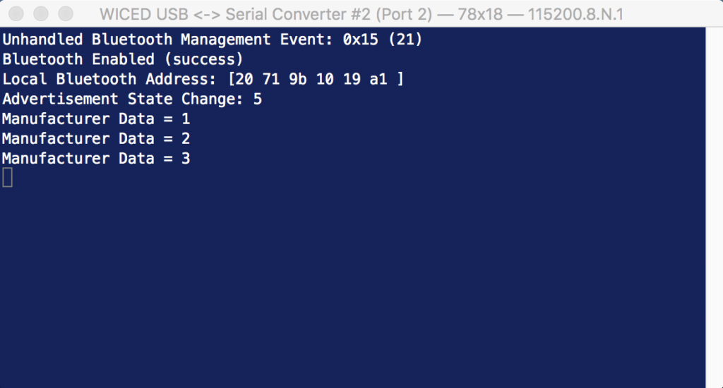
OK now when I run the program and start scanning I get this. Which makes good sense.
But if I run the scanning for a while, I get this. Why does it do this transition to “BTM_BLE_SCAN_TYPE_LOW_DUTY”?
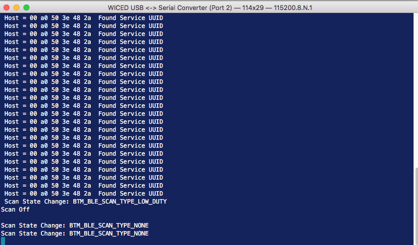
The answer to that question can be found on line 53 of “wiced_bt_cfg.c”. That “5” means scan at high duty cycle for 5 seconds, then go to low duty cycle scanning for 5 more seconds then stops scanning. This is done to save power as scanning is very current consuming. If you want to keep scanning forever, change those values to 0 (which means stay in that mode forever)
    /* BLE Scan Settings */
    .ble_scan_cfg = {
        .scan_mode =                        BTM_BLE_SCAN_MODE_PASSIVE,                                  /**< BLE Scan Mode (BTM_BLE_SCAN_MODE_PASSIVE or BTM_BLE_SCAN_MODE_ACTIVE) */

        /* Advertisement Scan Configuration */
        .high_duty_scan_interval =          WICED_BT_CFG_DEFAULT_HIGH_DUTY_SCAN_INTERVAL,               /**< High Duty Scan Interval */
        .high_duty_scan_window =            WICED_BT_CFG_DEFAULT_HIGH_DUTY_SCAN_WINDOW,                 /**< High Duty Scan Window */
        .high_duty_scan_duration =          5,                                                          /**< High Duty Scan Duration in seconds (0 for infinite) */

        .low_duty_scan_interval =           WICED_BT_CFG_DEFAULT_LOW_DUTY_SCAN_INTERVAL,                /**< Low Duty Scan Interval */
        .low_duty_scan_window =             WICED_BT_CFG_DEFAULT_LOW_DUTY_SCAN_WINDOW,                  /**< Low Duty Scan Window */
        .low_duty_scan_duration =           5,                                                          /**< Low Duty Scan Duration in seconds (0 for infinite) */
Make the Connection
Now that I have found a device, how do I make a connection? Simple, call wiced_bt_gatt_connect. The other thing that you want to do is turn off the scanning by calling wiced_bt_ble_scan with “BTM_BLE_SCAN_TYPE_NONE”.
// This function is called when an advertising packet is received.
void newAdvCallback(wiced_bt_ble_scan_results_t *p_scan_result, uint8_t *p_adv_data)
{

    uint8_t length;

    uint8_t *serviceUUID = wiced_bt_ble_check_advertising_data(p_adv_data,BTM_BLE_ADVERT_TYPE_128SRV_COMPLETE,&length);
    if(serviceUUID && memcmp(serviceUUID,matchServiceUUID,16) == 0)
    {
        WICED_BT_TRACE("Host = %B Found Service UUID\n ",p_scan_result->remote_bd_addr);
        wiced_bt_gatt_le_connect(p_scan_result->remote_bd_addr,p_scan_result->ble_addr_type,BLE_CONN_MODE_HIGH_DUTY,WICED_TRUE);
        wiced_bt_ble_scan(BTM_BLE_SCAN_TYPE_NONE,FALSE,newAdvCallback);


    }

}
All of the functions that let you exchange data require a connection id. The 20719 lets you handle multiple BLE (and Bluetooth Classic) connections and each connection will have a different connection id. At the top of your project the easiest thing to do is create a global variable to keep track of the connection id. Initialize it to 0 meaning no connection.
static uint16_t conn_id=0;
You might have noticed that the connection api was “…gatt_le_connect”. This means that while you are connected, almost all of the interaction will happen with a gatt callback which looks like this. Add it to the function declarations at the top of your project.
static wiced_bt_gatt_status_t gatt_callback( wiced_bt_gatt_evt_t event, wiced_bt_gatt_event_data_t *p_data);
And in the application_init register your callback.
wiced_bt_gatt_register( gatt_callback );
Now we need to actually create the callback function. This function will just be a switch to look at what type of gatt event just happened. We will start with the only case being the connection event. If this event is a connection, save the connection id and print out the bd address of the peripheral. If this is a disconnect, then set the connection id back to 0.
wiced_bt_gatt_status_t gatt_callback( wiced_bt_gatt_evt_t event, wiced_bt_gatt_event_data_t *p_data)
{
    wiced_bt_gatt_status_t result = WICED_BT_SUCCESS;

    switch( event )
    {
    case GATT_CONNECTION_STATUS_EVT:
        if ( p_data->connection_status.connected )
        {
            WICED_BT_TRACE("Connected\r\n");
            wiced_bt_gatt_connection_status_t *p_conn_status = &p_data->connection_status;
            conn_id         =  p_conn_status->conn_id;
            WICED_BT_TRACE("Connection ID=%d\r\n",conn_id);
        }
        else
        {
            WICED_BT_TRACE(("Disconnected\r\n"));
            conn_id = 0;
        }
        break;


    default:
        WICED_BT_TRACE("Unknown GATT Event %d\n",event);
        break;
    }

    return result;
}
The last thing you need to do to get the connection to work is modify wiced_bt_cfg.c and increase the .client_max_links to at least 1.
    /* GATT Configuration */
    .gatt_cfg = {
        .appearance =                       0x0000,                                                     /**< GATT Appearance */
        .client_max_links =                 1,                                                          /**< Client Config: Maximum number of servers that local client can connect to */
        .server_max_links =                 0,                                                          /**< Server Config: Maximum number of remote client connections allowed by local server */
        .max_attr_len =                     512,                                                        /**< Maximum attribute length; wiced_bt_cfg must have a corresponding buffer pool that can hold this length */
        .max_mtu_size =                     515,                                                        /**< Maximum MTU size for GATT connections, should be between 23 and (max_attr_len + 5) */
    },
We setup all of the code to make a connection. How about the disconnect? That is also easy. Il add a new case the user interface ‘d’ to call wiced_bt_gatt_disconnect.
    case 'd':
        wiced_bt_gatt_disconnect(conn_id);
        break;
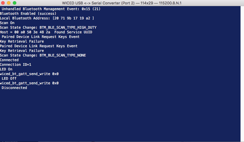
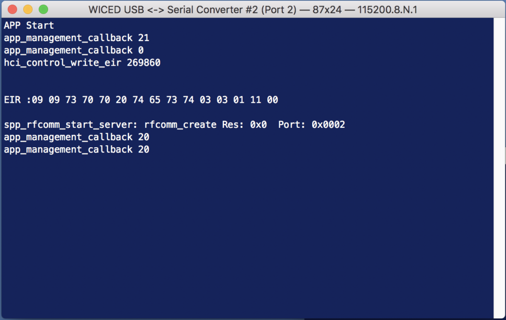
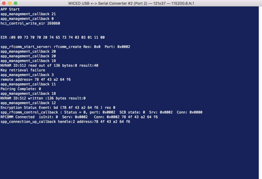
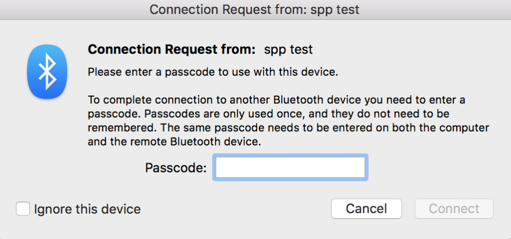
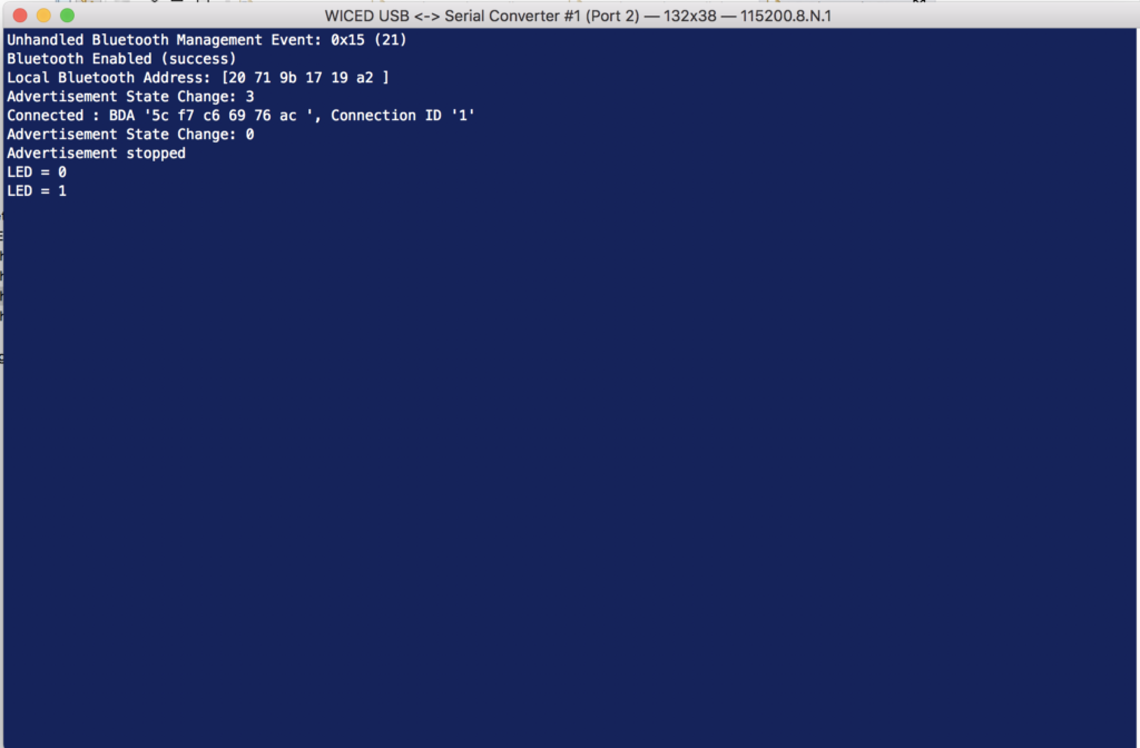
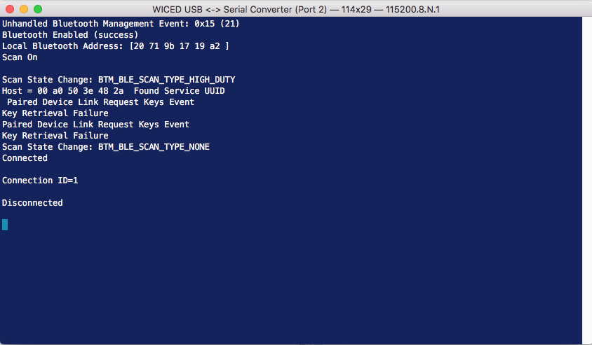
Now when I program and test you can see that I can make a connection (which barfs out a bunch of messages about pairing not working) and then I can disconnect.
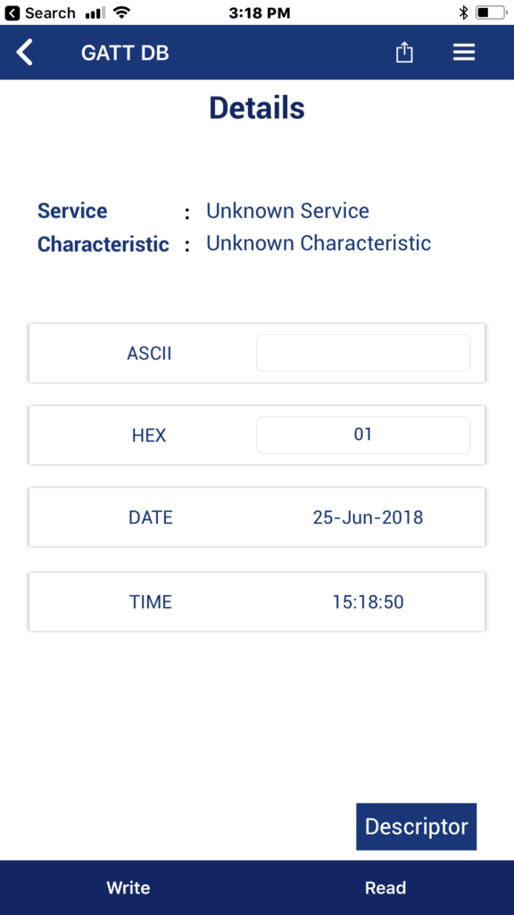
Write the LED Characteristic
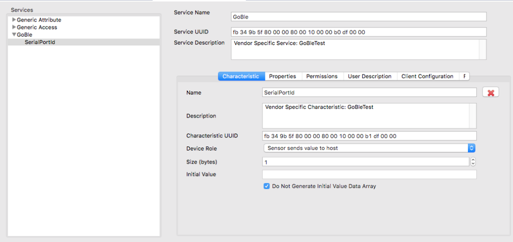
Finally we are ready to write the LED. You might recall from the original peripheral project that it has a Service with two characteristics, one for an LED and one for a CapSense value. Here is the customizer screen.
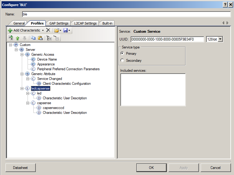
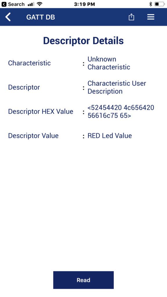
You might recall that all BLE transactions take place in reference to a handle (just a 16 bit number in the Attribute Database). But what is the handle of the LED characteristic? You can see from the PSoC Creator project in file ble_custom.c that the handle of the LED characteristic is 0x0E. Note: this is a seriously bad way to find out the handle for a characteristic. The correct way is to use service discovery which Ill show you in the third article.
const CYBLE_CUSTOMS_T cyBle_customs[0x01u] = {

    /* ledcapsense service */
    {
        0x000Cu, /* Handle of the ledcapsense service */
        {

            /* led characteristic */
            {
                0x000Eu, /* Handle of the led characteristic */

                /* Array of Descriptors handles */
                {
                    0x000Fu, /* Handle of the Characteristic User Description descriptor */
                    CYBLE_GATT_INVALID_ATTR_HANDLE_VALUE,
                },
            },

            /* capsense characteristic */
            {
                0x0011u, /* Handle of the capsense characteristic */

                /* Array of Descriptors handles */
                {
                    0x0012u, /* Handle of the capsensecccd descriptor */
                    0x0013u, /* Handle of the Characteristic User Description descriptor */
                },
            },
        },
    },
};
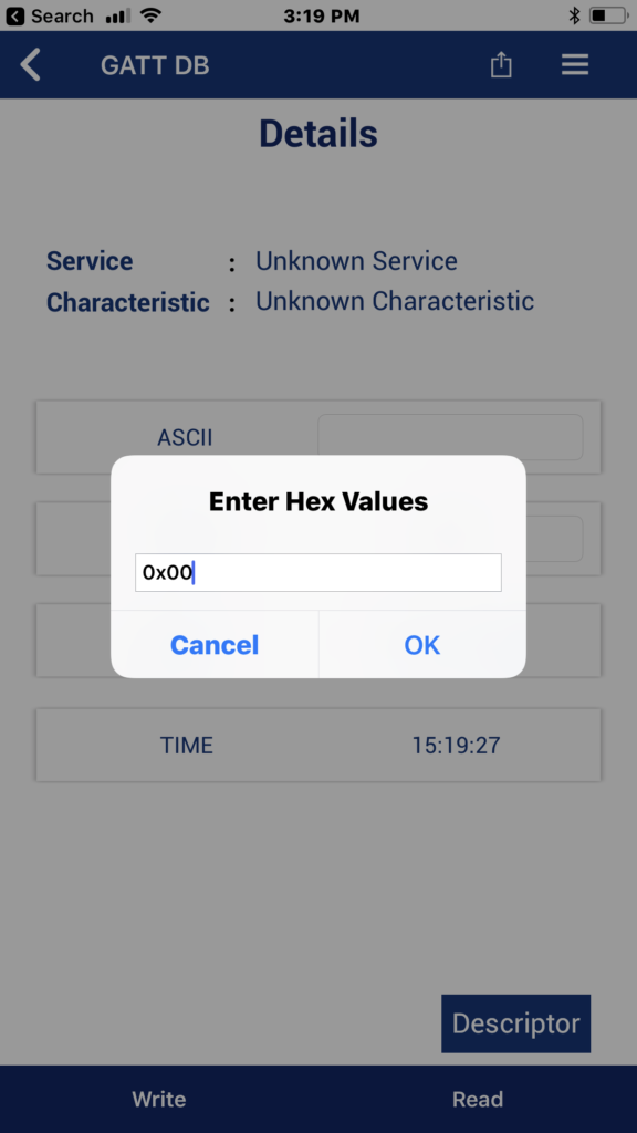
In order to write the characteristic I will create a new function that will let me write a 0 or 1. This function simply
- Checks to make sure that there is a connection
- Allocates a block of memory to hold the structure required to send the write
- Sets up the structure with the handle, offset, length and value
- Send the write
- Frees the buffer
// writeLED is a function to send either a 1 or a 0 to the LED Characteristic
// This function will check and see if there is a connection and we know the handle of the LED
// It will then setup a write... and then write
void writeLed(uint8_t val)
{
    if(conn_id == 0)
        return;


    wiced_bt_gatt_value_t *p_write = ( wiced_bt_gatt_value_t* )wiced_bt_get_buffer( sizeof( wiced_bt_gatt_value_t ));
    if ( p_write )
        {
            p_write->handle   = 0x0E; // Hardcoded handle
            p_write->offset   = 0;
            p_write->len      = 1;
            p_write->auth_req = GATT_AUTH_REQ_NONE;
            p_write->value[0] = val;

            wiced_bt_gatt_status_t status = wiced_bt_gatt_send_write ( conn_id, GATT_WRITE, p_write );

            WICED_BT_TRACE("wiced_bt_gatt_send_write 0x%X\r\n", status);

            wiced_bt_free_buffer( p_write );
        }

}
I want to use the buffer allocation functions, so at the top of my program Ill include the wiced_memory.h header file.
#include "wiced_memory.h"
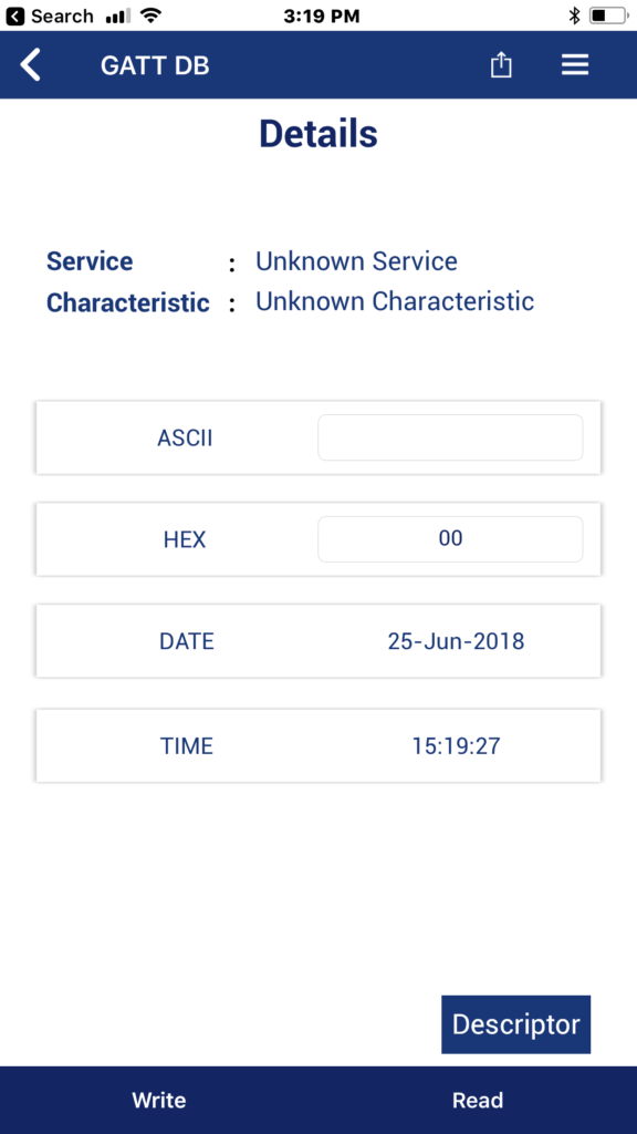
To make the writes work I just call the “writeLed” function in the keyboard handler.
    case '0':
        WICED_BT_TRACE("LED Off\r\n");
        writeLed(0);
        break;

    case '1':
        WICED_BT_TRACE("LED On\r\n");
        writeLed(1);
        break;
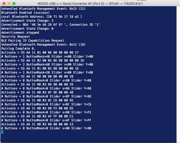
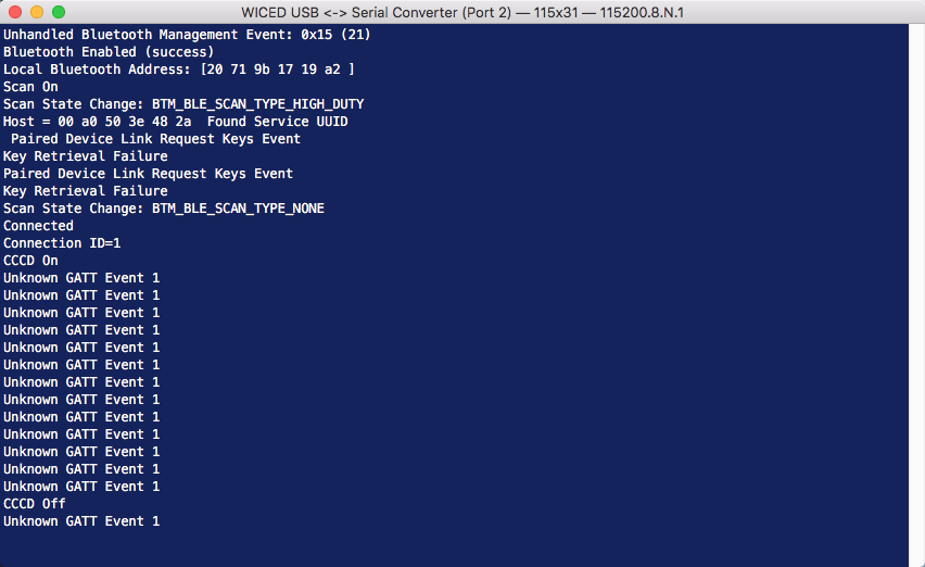
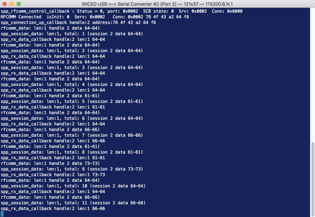
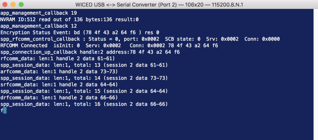
Now when I test, everything is working.
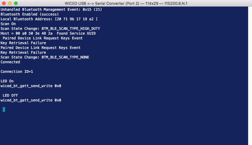
And here are the two development kits talking nice to each other (at least it works from 2 inches away 🙂 )
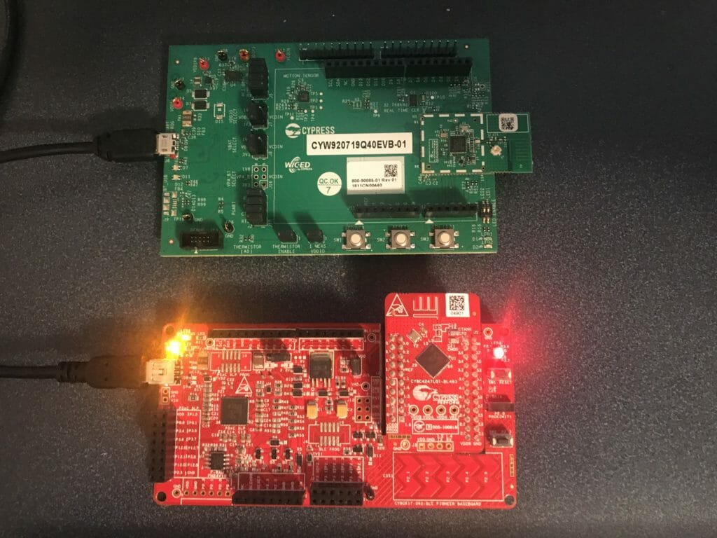
You can find all of the source code for these projects at github.com/iotexpert/PSoc4BLE-Central