PSoC FreeRTOS – Sharing the I2C Bus

Summary

I have gotten quite a few questions about my PSoC FreeRTOS series of Articles.  One question was: “I have a bunch of different I2C sensors, what is a good PSoC FreeRTOS scheme to share the I2C bus?”  When I thought about this question there were a number of possible firmware architectures that could be used:

  1. Each sensor has a thread, and there is a global Mutex to lock/unlock the I2C bus
  2. There is single thread that reads and writes to all of the sensors (oh…wait… that looks like the old bare metal while(1); )
  3. There is a single I2C thread that can take requests execute them, and then feed data back to the calling thread

After thinking about it a bit, I decided to use the 3rd scheme as it allows me to

  • Reuse the I2C interface code (all the sensors have a register map that you read/write)
  • Handle all of the timing issues in one place (instead of duplicated)
  • Isolate the I2C interface from all of the threads (could be replaced with SPI or something else later)

In this article I will show you:

  • The register based I2C interface that is in common use with sensors
  • The design of the PSoC FreeRTOS firmware with a single I2C interface thread
  • The PSoC FreeRTOS firmware implementation
  • A test case using the CY8CKIT-044

Interfacing with I2C Sensor Registers using PSoC FreeRTOS

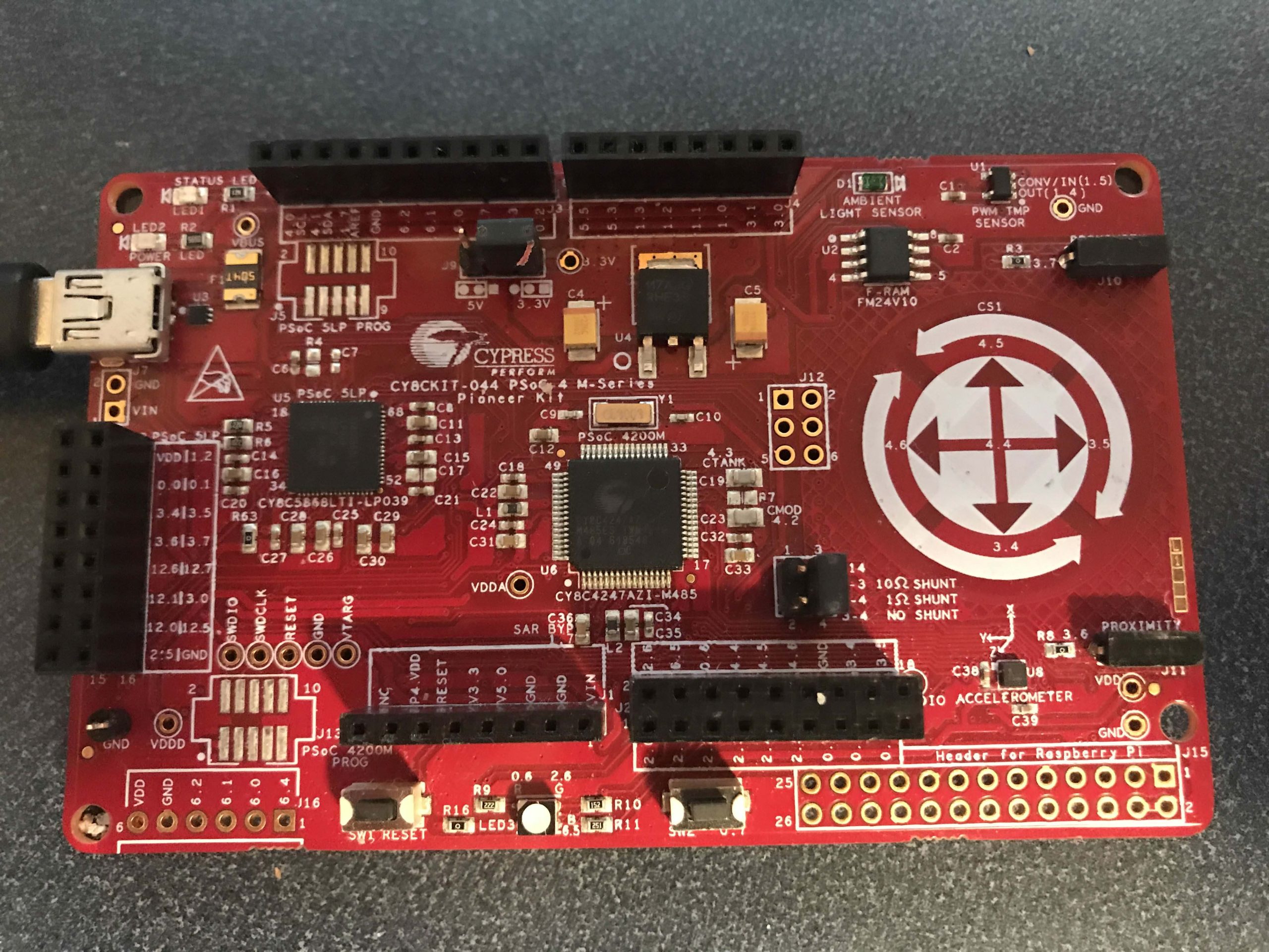
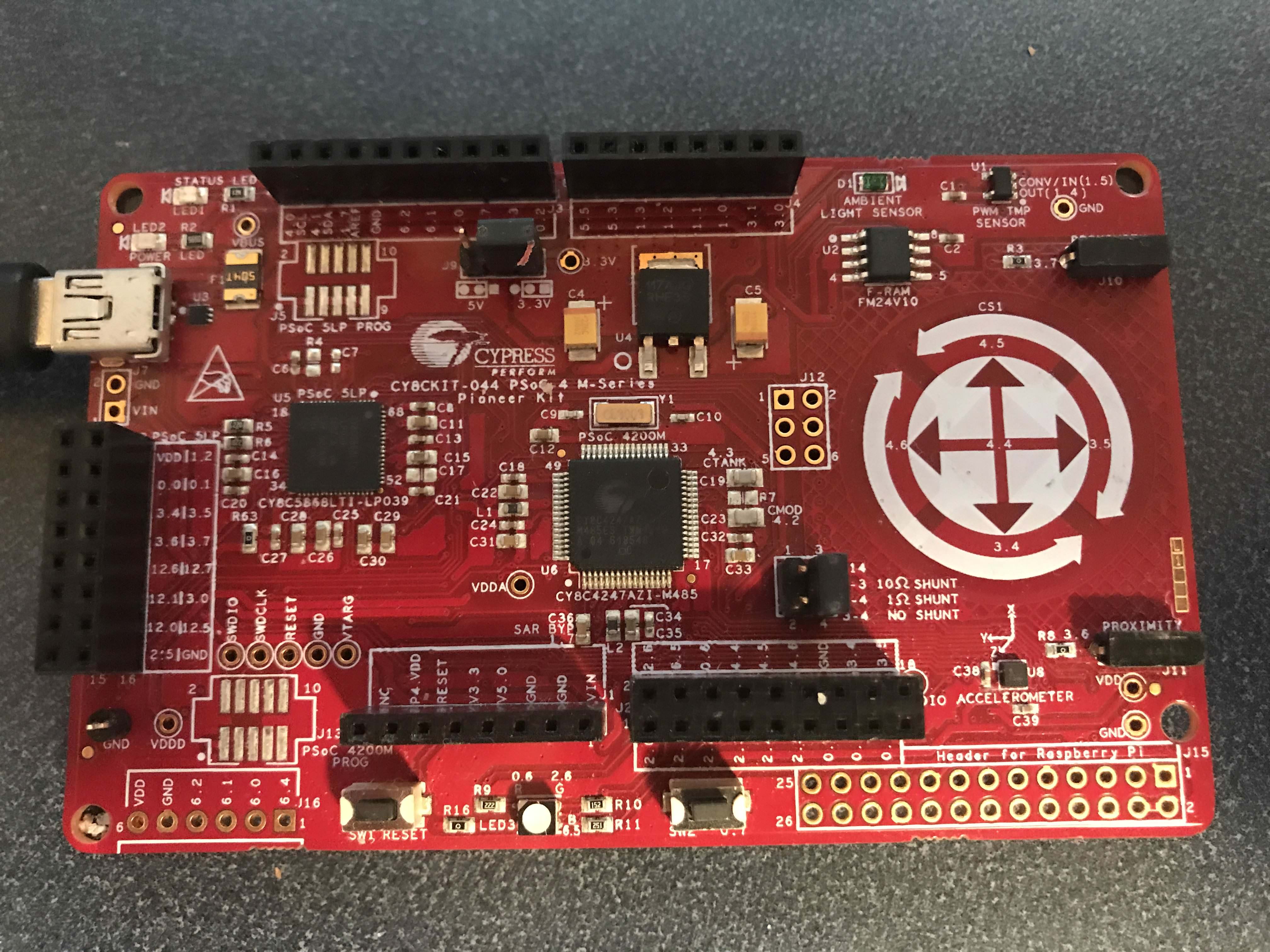
The CY8CKIT-044 (on of my favorite Cypress kits) has two devices attached to the I2C bus, so it made a perfect test platform.  On the front there is a Cypress FM24V10 FRAM and a Kionix KXTJ2-1009 I2C Accelerometer.

CY8CKIT-044 Development Kit Front

And on the back there is a nice little picture on the silkscreen that gives the FRAM I2C Address as 0x50, the I2C Address of the Accelerometer as 0X0F and the I2C pins as P4.0/P4.1 CY8CKIT-044 Development Kit Back
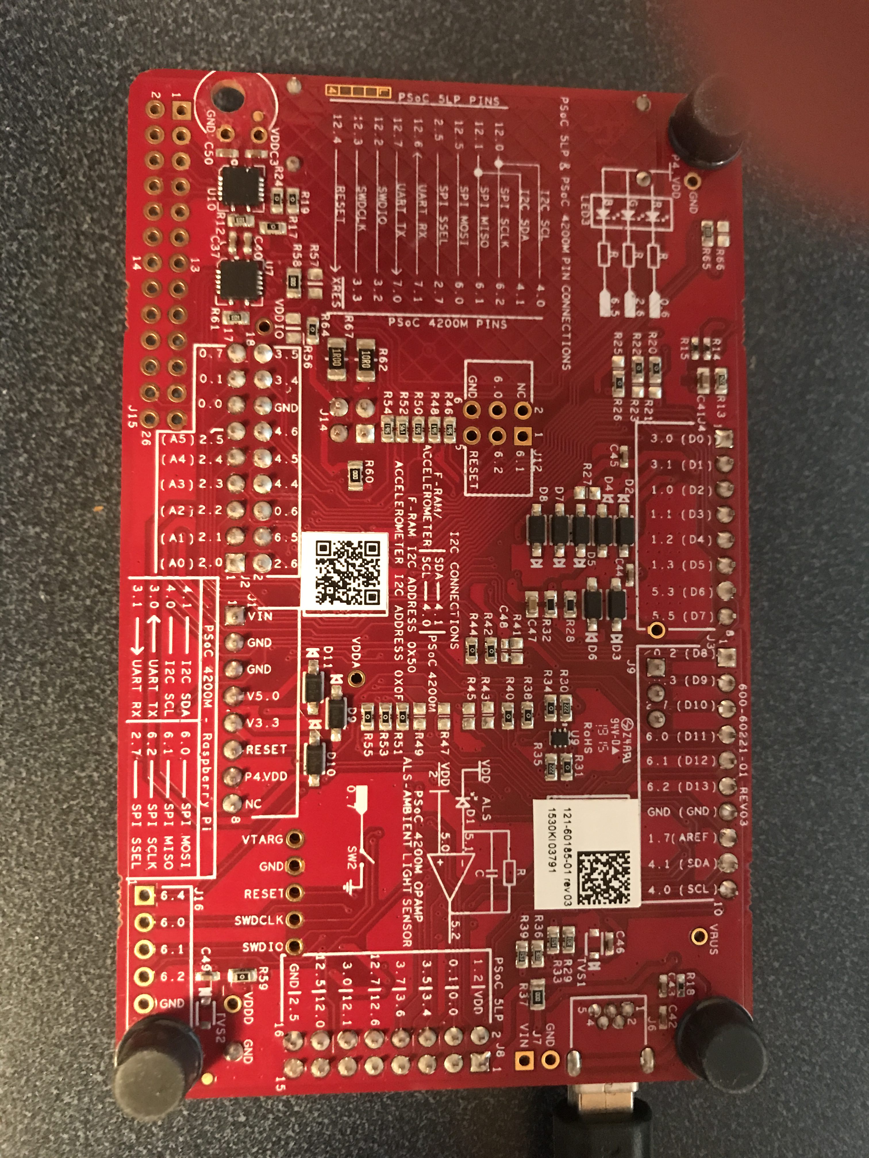
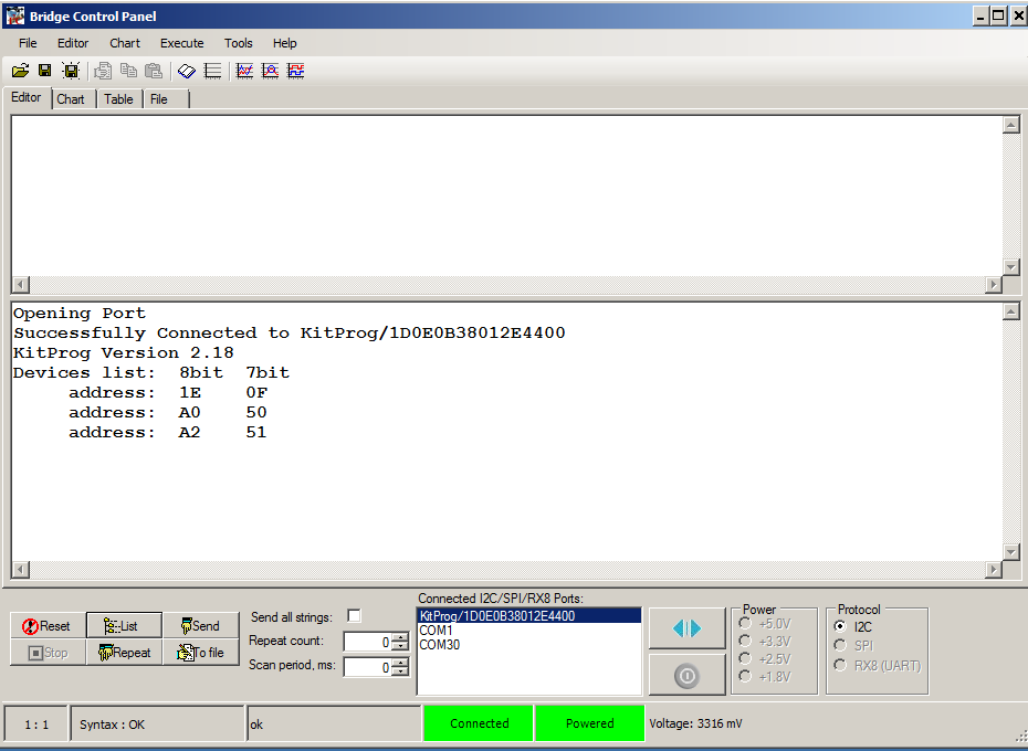
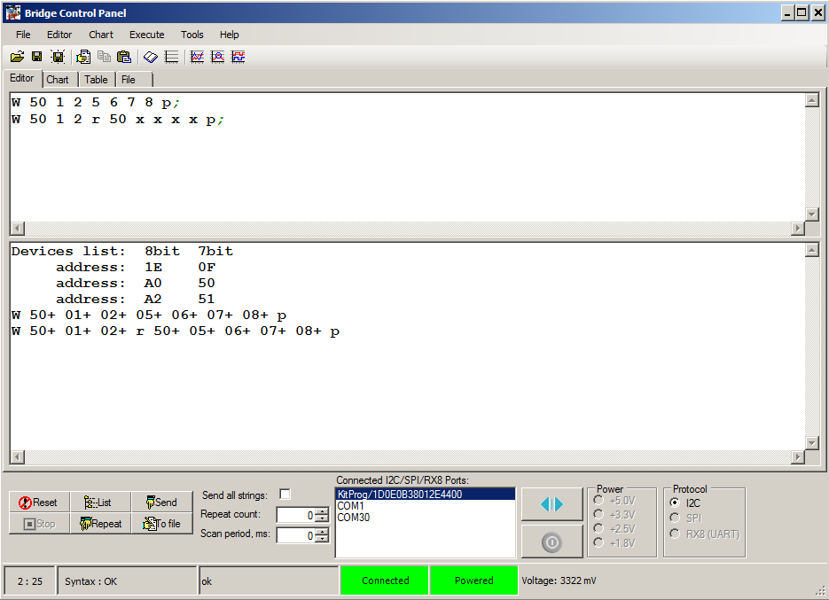
When I probe the I2C Bus using the bridge control panel I see that three I2C devices respond, 0x0F (the KXTJ2-1009), 0x50/0x51 (the FRAM.)

Bridge control panel probing I2C bus on CY8CKIT-044

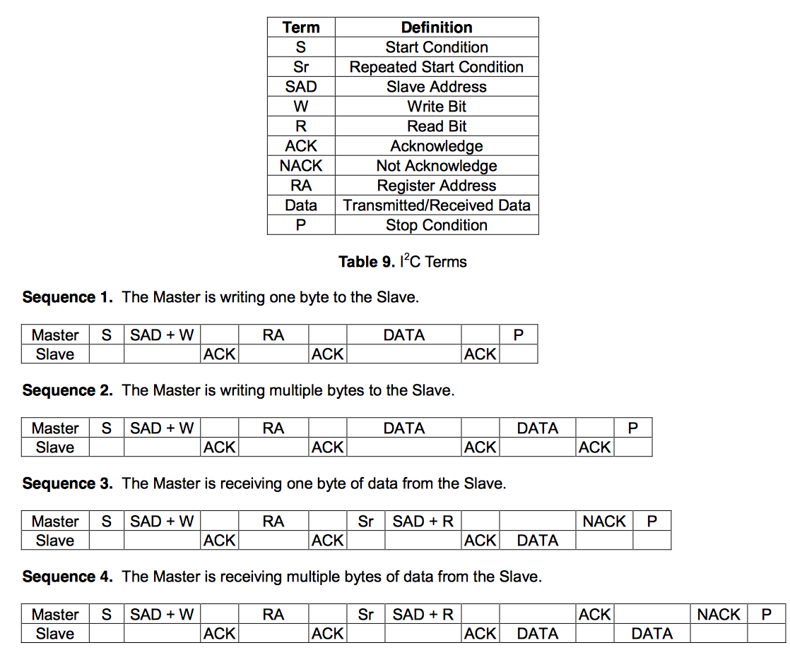
So, how do you talk to the devices?  It turns out that both of these devices respond to the very common I2C device scheme which is called “EZI2C” inside of Cypress.  The scheme goes like this:

  • The chip is organized into registers
  • Each register has an address
  • Addresses are either 8-bits or 16-bits
  • To write an address you can send a string of bytes like:  I2C Start, I2C Address + W, Register Address,  Value to write, Stop
  • To read an address you can send a string of bytes like:  I2C Start, I2C Address + W, Register Address, Restart, Read, Stop

A simplification is that you can keep writing (or reading) and it will automatically goes to the next address without you having to send the next address. The easiest thing to do is show an example with the FRAM.

The FRAM has 128K addresses so it uses 16-bit addresses.  For example to save the values 5,6,7,8 into the register 0x0123 you would send:

  • 0x50, W, 0x01, 0x02, 0x05, 0x06, 0x07, 0x08, Stop  (in the bridge control panel the command is W 50 1 2 5 6 7 8 p)

To read back those addresses you would send

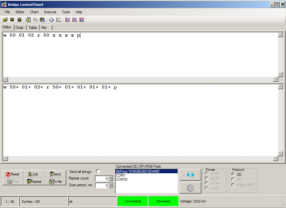
  • 0x50, W, 0x01, 0x02, restart, read read read read Stop  (in the bridge control panel the command is W 50 1 2 R 50 x x x x p)

Writing to Cypress FRAM using Bridge Control Panel

The interface is similar for the Kionix KXTJ2-1009.  When you look at the datasheet you will see on page 17 their description of the EZI2C protocol:

Kionix KXTJ2-1009 Datasheet

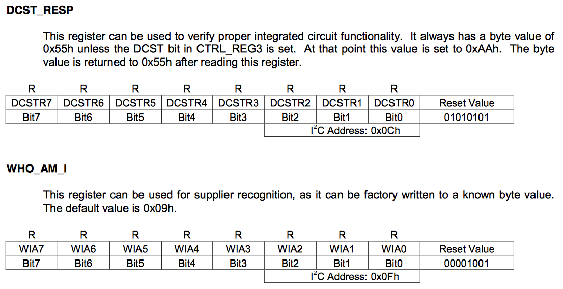
Then on page 20 they start describing the registers, and on page 21 they describe two registers (called DCST_RESP and WHO_AM_I) that will always respond with known values.

Kionix KXTJ2-1009 Datasheet

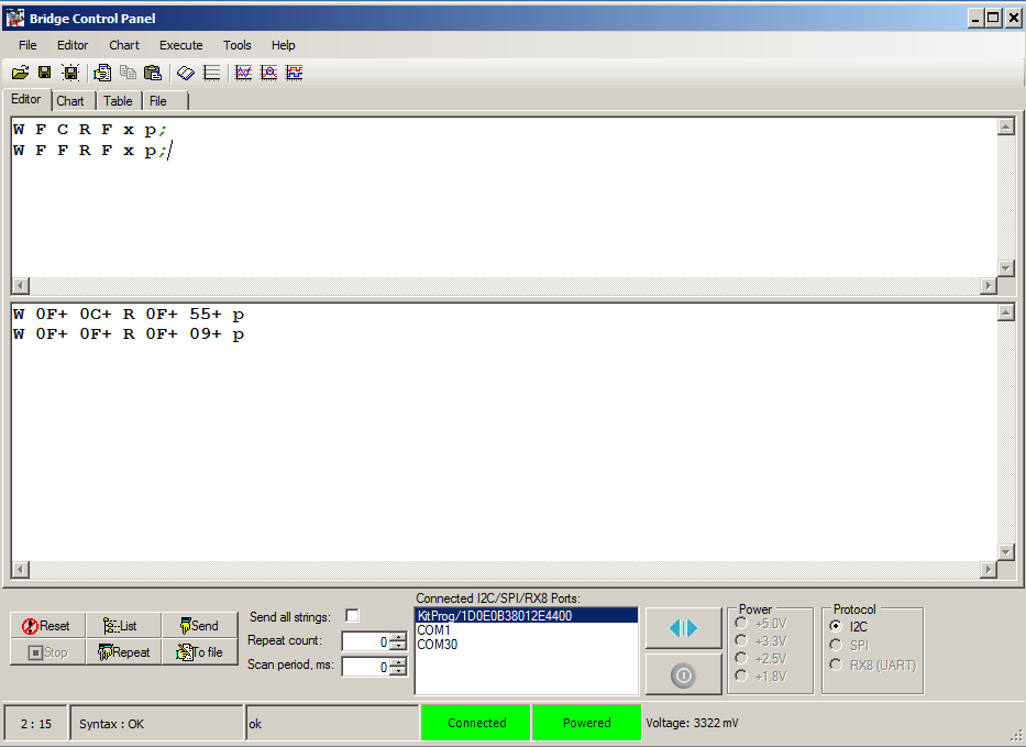
To verify the operation I send read commands using the Bridge Control panel to those registers, which respond with 55 and 9 just like the datasheet says that they should.

Reading from Kionix KXTJ2-1009 Using Bridge Control Panel

Designing PSoC FreeRTOS FW for I2C Register Based Sensors

From the previous section(s) we know that

  1. Two totally different devices, a memory and an accelerometer, can be accessed using exactly the same protocol
  2. It may take a while to complete I2C transactions (4 bytes @ 400kb/s = 87.5uS).
  3. The I2C master is a “shared” interface on the board, but multiple threads may want to perform transactions

These facts lead up to the conclusion that it would be nice to:

  • Have a standard software interface to I2C devices that use the EZI2C protocol
  • Have a non-blocking thread to run the interface
  • Share the I2C
  • Use PSoC FreeRTOS (the whole point)

With all of that in mind I created “i2cmaster.h”, the public interface to a PSoC FreeRTOS thread that will run the EZI2C protocol.  It defines two public functions

  • i2cm_Task – The thread that will need to be started to run all of the transactions
  • i2cm_runTransaction – The thread safe public interface which will send the transaction to the i2cm_Task

To run a transaction you need to have a transaction.  I defined a new type called “i2cm_transaction”.  This type is a structure that contains all of the information that is required to perform a transaction.  The input is split into three sections:

  • The I2C Address, the Register Address (and type 8-bit or 16-bit), and if the transaction is a Read or a Write
  • The number of bytes you want to read/write and a pointer to the data
  • The number of bytes that were processed (an output of the task)… plus an optional semaphore that will be given if you want a blocking transaction
#include <project.h>
#include "FreeRTOS.h"
#include "semphr.h"

#ifndef I2C_MASTER_H
#define I2C_MASTER_H

    
typedef enum i2cm_transactionMethod {
    I2CM_READ,
    I2CM_WRITE
} i2cm_transactionMethod_t;

typedef enum i2cm_registerAddresType {
    I2CM_BIT8,
    I2CM_BIT16
 
} i2cm_registerAddressType_t;


typedef struct i2cm_transaction {
    i2cm_transactionMethod_t i2cm_method;        // I2CM_READ or I2CM_WRITE
    uint8_t i2cm_address;                        // The I2C Address of the slave
    i2cm_registerAddressType_t i2cm_regType;     // I2CM_8BIT or I2CM_16BIT
    uint16_t i2cm_register;                      // The register in the slave
    
    uint8_t *i2cm_bytes;                         // A pointer to the data to be written (or a place to save the data)
    int i2cm_byteNum;                            // How many bytes are in the request

    int *i2cm_bytesProcessed;                    // A return value with the number of bytes written 
    SemaphoreHandle_t i2cm_doneSemaphore;        // If you want a semaphore flaging that the transaction is done
 
} i2cm_transaction_t;

void i2m_Task(void *arg);                  // The main thread function... you should start it in the RTOS

void i2cm_runTransaction(i2cm_transaction_t *i2cm_Transaction); // The public interface

#endif

With the public interface setup you will be able to run code that does exactly the same thing as you did in the bridge control panel.  For instance you can query the accelerometer “WHO_AM_I” register:

                    mytransaction.i2cm_method = I2CM_READ;
                    mytransaction.i2cm_address = 0x0F;            // Acelleromter I2C Address
                    mytransaction.i2cm_regType = I2CM_BIT8;       // 8-bit addressing
                    mytransaction.i2cm_register = 0x0F;           // WHO_AM_I Register
               
                    mytransaction.i2cm_byteNum = 1;               // One byte
                    mytransaction.i2cm_bytes = data;
               
                    mytransaction.i2cm_bytesProcessed = &byteCount;
                    mytransaction.i2cm_doneSemaphore = mySemaphore;
                    i2cm_runTransaction(&mytransaction);
                    
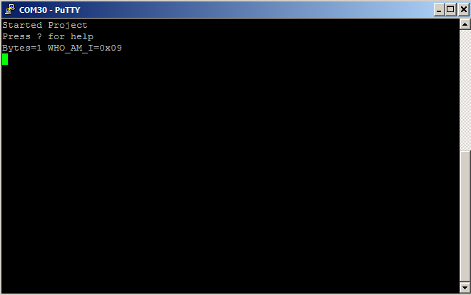
                    sprintf(buff,"Bytes=%d WHO_AM_I=0x%02X\n",byteCount,data[0]);
                    UART_UartPutString(buff);          

Which will yield exactly the same result as the bridge control panel did:

PSoC FreeRTOS: I2C Thread output from Kionix KXTJ2-1009

Implementing a PSoC FreeRTOS I2C Master Library

From the previous section we know the public interface.  But how does it work?  When the PSoC FreeRTOS i2cm_Task starts it:

  • Starts up the hardware I2C block
  • It makes a queue.  The queue will hold transactions which are waiting to be processed.  This is how multiple processes will put requested transactions into the queue, and the I2C master will deal with them one at a time in the order they were placed in the queue.
  • It starts up the infinite loop and waits for a transaction to be placed in the queue.
void i2cm_Task(void *arg)
{
    
    // The argument is the size of the queue
    uint32_t queueSize = (uint32_t)arg; // cast the arg
    
    I2C_Start(); // turn on the I2C Master
     
    i2cm_transaction_t i2cm_transaction; // A scratch transaction
    i2cm_transactionQueue = xQueueCreate(queueSize, sizeof(i2cm_transaction_t));
    
    uint32_t rval; // all of the I2C functions return a uint32_t
    
    while(1)
    {
        int i;
 
        // Wait until something gets put in the queue
        if(xQueueReceive(i2cm_transactionQueue,&i2cm_transaction,portMAX_DELAY) == pdTRUE)

The public interface to the whole system is i2cm_runTransaction.  It takes the transaction structure and pushes it onto the queue for the main thread to process.  If the user has asked to wait for completion then it also holds until the semaphore is given by the main loop.

// the i2cm_runTransaction function is the public interace to the system
// This function is thread safe (it can be called from any thread)
// It will queue up an I2C tranaction and then wait (if there is a semaphore handle)
void i2cm_runTransaction(i2cm_transaction_t *i2cm_transaction)
{
    if(xQueueSend(i2cm_transactionQueue,i2cm_transaction,portMAX_DELAY) != pdTRUE)
    {
        // Highly bad
        CYASSERT(0); // 
    }
    if(i2cm_transaction->i2cm_doneSemaphore)
        xSemaphoreTake(i2cm_transaction->i2cm_doneSemaphore,portMAX_DELAY);
}

The last part of the system is the main transaction processing loop which:

  • Waits for a transaction
  • Sends a start, then write the I2C address and register address (lines 65-75)
  • If it is a write, then write the bytes (lines 80-85)
  • If it is a read, then read then read bytes (lines 89-102)
  • Send a stop (lines 105-106)
  • If the user asked for a semaphore, give it. (lines 112-113)
        // Wait until something gets put in the queue
        if(xQueueReceive(i2cm_transactionQueue,&i2cm_transaction,portMAX_DELAY) == pdTRUE)
        {
            // Begining of an I2C transaction
            *i2cm_transaction.i2cm_bytesProcessed = 0;
            // First write the register address
            rval = I2C_I2CMasterSendStart(i2cm_transaction.i2cm_address,I2C_I2C_WRITE_XFER_MODE);
            if(rval != I2C_I2C_MSTR_NO_ERROR) goto cleanup;
            
            if(i2cm_transaction.i2cm_regType == I2CM_BIT16) // if a 16 bit register then send the high
            {
                rval = I2C_I2CMasterWriteByte((i2cm_transaction.i2cm_register >> 8) & 0xFF);
                if(rval != I2C_I2C_MSTR_NO_ERROR) goto cleanup;
            }
            rval = I2C_I2CMasterWriteByte((i2cm_transaction.i2cm_register ) & 0xFF); // send the low byte
            if(rval != I2C_I2C_MSTR_NO_ERROR) goto cleanup;
            
            // if w send ...
            switch(i2cm_transaction.i2cm_method) // Look at the type of transaction they want to do...
            {
                case I2CM_WRITE:  // If it is a write... then just send out the bytes
                for(i=0; i < i2cm_transaction.i2cm_byteNum;i++)
                {
                    rval = I2C_I2CMasterWriteByte(i2cm_transaction.i2cm_bytes[i]);
                    if(rval != I2C_I2C_MSTR_NO_ERROR) goto cleanup;
                    *i2cm_transaction.i2cm_bytesProcessed += 1;
                }
                break;
            
                case I2CM_READ: // If it is a read.. then do a restart with READ... then read n-1 bytes
                rval = I2C_I2CMasterSendRestart(i2cm_transaction.i2cm_address,I2C_I2C_READ_XFER_MODE);
                if(rval != I2C_I2C_MSTR_NO_ERROR) goto cleanup;
                for(i=0; i < i2cm_transaction.i2cm_byteNum-1;i++)
                {
                    i2cm_transaction.i2cm_bytes[i] = I2C_I2CMasterReadByte(I2C_I2C_ACK_DATA);
                    if(i2cm_transaction.i2cm_bytes[i] & 0x10000000) goto cleanup;
                    *i2cm_transaction.i2cm_bytesProcessed += 1;
                }
                // Then read the last byte and NAK (saying you are done)
                i2cm_transaction.i2cm_bytes[i2cm_transaction.i2cm_byteNum-1] = I2C_I2CMasterReadByte(I2C_I2C_NAK_DATA);
                if(i2cm_transaction.i2cm_bytes[i2cm_transaction.i2cm_byteNum-1] & 0x10000000) goto cleanup;
                *i2cm_transaction.i2cm_bytesProcessed += 1;
                break;
            }

            rval = I2C_I2CMasterSendStop();
            if(rval != I2C_I2C_MSTR_NO_ERROR) goto cleanup;

            cleanup:
            CYASSERT(rval == 0); // something really bad happend
          
           // If they ask for a semphore when done... then give it
            if(i2cm_transaction.i2cm_doneSemaphore)
                xSemaphoreGive(i2cm_transaction.i2cm_doneSemaphore);     
        }

I2C Sensor Library on the CY8CKIT-044 (FRAM)

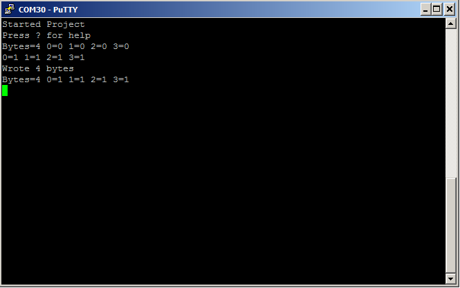
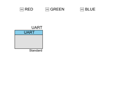
In order to test the FRAM  I define a buffer in the RAM of the PSoC called “data”.  Then I setup three commands that can be executed from the UART Thread which will:

  • q – read 4 bytes from register 0x0102 into the data[] array
  • w -write 4 bytes from the data[] array into the FRAM register 0x0102
  • i – increment the values in the data[] array.

The code is simple:

           case 'q':
                    mytransaction.i2cm_address = 0x50;
                    mytransaction.i2cm_regType = I2CM_BIT16;
                    mytransaction.i2cm_byteNum = 4;
                    mytransaction.i2cm_register = 0x0102;
                    mytransaction.i2cm_method = I2CM_READ;
                    mytransaction.i2cm_bytesProcessed = &byteCount;
                    mytransaction.i2cm_bytes = data;
                    mytransaction.i2cm_doneSemaphore = mySemaphore;
                    i2cm_runTransaction(&mytransaction);
                    sprintf(buff,"Bytes=%d 0=%d 1=%d 2=%d 3=%d\n",byteCount,data[0],data[1],data[2],data[3]);
                    UART_UartPutString(buff);                  
            break;
            case 'i': // This will increment the values (that you read presumably from the FRAM
                    data[0] += 1;
                    data[1] += 1;
                    data[2] += 1;
                    data[3] += 1;
                    sprintf(buff,"0=%d 1=%d 2=%d 3=%d\n",data[0],data[1],data[2],data[3]);
                    UART_UartPutString(buff);
            break;
           
            case 'w': //This will write 4 values to register 0 in the FRAM
                    mytransaction.i2cm_address = 0x50;
                    mytransaction.i2cm_regType = I2CM_BIT16;
                    mytransaction.i2cm_byteNum = 4;
                    mytransaction.i2cm_register = 0x0102;
                    mytransaction.i2cm_method = I2CM_WRITE;
                    mytransaction.i2cm_bytesProcessed = &byteCount;
                    mytransaction.i2cm_bytes = data;
                    mytransaction.i2cm_doneSemaphore = mySemaphore;
                    i2cm_runTransaction(&mytransaction);
                    sprintf(buff,"Wrote %d bytes\n",byteCount);
                    UART_UartPutString(buff);
            break;

To test:

  • Press ‘q’ to read from the FRAM into data[]
  • Press ‘i’ to increment the values in data[]
  • Press ‘w’ to write the data[] back into the FRAM
  • Press ‘q’ to make sure that the values were written
  • Use the bridge control panel to read the data to make sure that it is right.

PSoC FreeRTOS: I2C Thread output from Cypress FRAM

Read/Write from Bridge Control Panel to Cypress FRAM

I2C Sensor Library on the CY8CKIT-044 (Accelerometer)

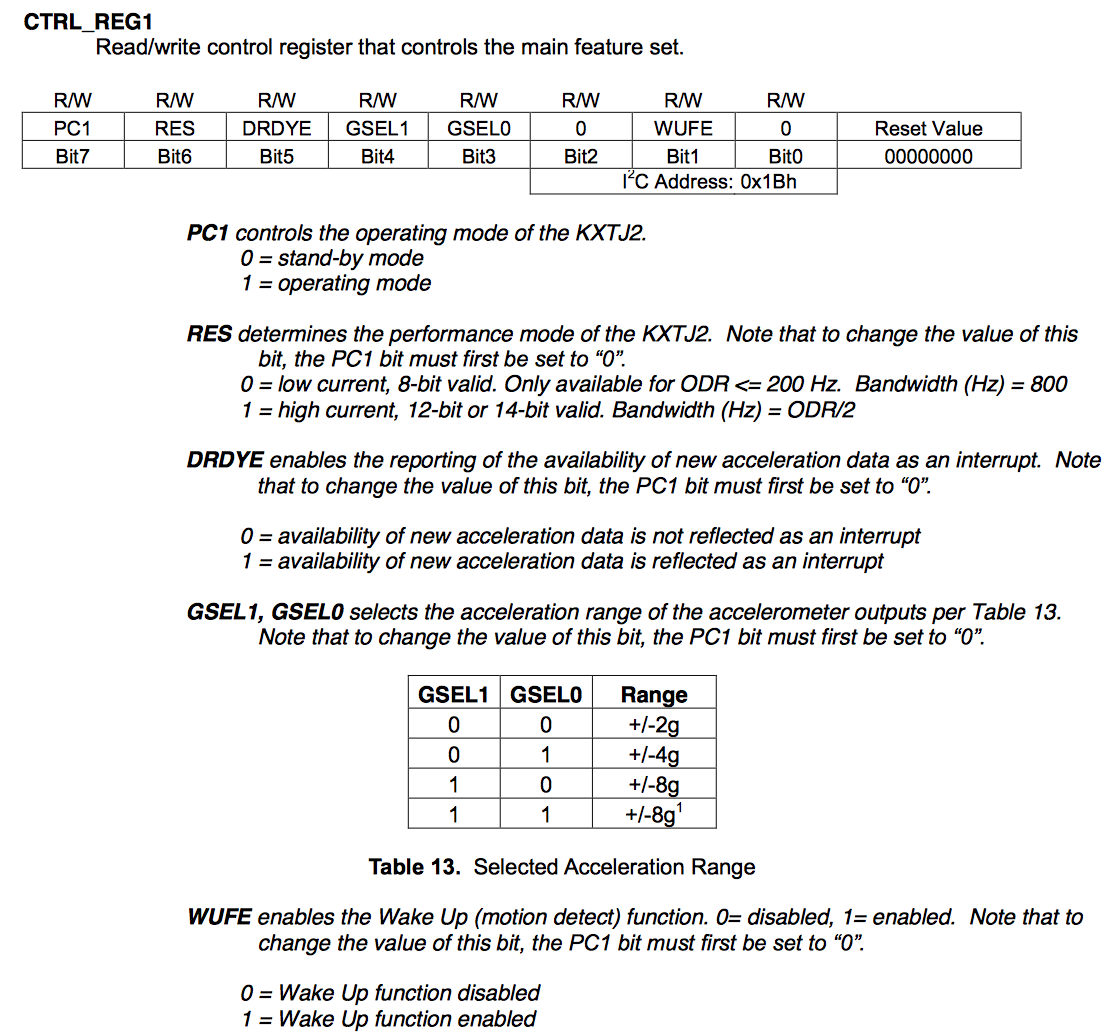
Finally, to test the Accelerometer I create a PSoC FreeRTOS thread which starts up and turns on the Accelerometer.  To turn on the accelerometer you need to write a 0b1000000 to register 0x1b (called the CTRL_REG_1)

// This task manages the accelerometer
// 
void accel_Task(void *arg)
{
    (void)arg;
    SemaphoreHandle_t mySemaphore;
    i2cm_transaction_t mytransaction;
    char buff[128];
    int x,y,z;
    int xs,ys,zs;
    
    int byteCount;
    accel_t myData;
    
    mySemaphore = xSemaphoreCreateBinary();
     
    // True of all read/writes
    mytransaction.i2cm_address = 0x0F;
    mytransaction.i2cm_regType = I2CM_BIT8;
    mytransaction.i2cm_bytesProcessed = &byteCount;
    
    // Initalize the acceleromter
    uint8_t setupData[] = {0b10000000};
    mytransaction.i2cm_method = I2CM_WRITE;
    mytransaction.i2cm_register = 0x1b; // CTRL_REG_1
    mytransaction.i2cm_byteNum = sizeof(setupData);
    mytransaction.i2cm_doneSemaphore = mySemaphore;
    mytransaction.i2cm_bytes = setupData;
    i2cm_runTransaction(&mytransaction);

Once the accelerometer is turned on, it will update 6 registers called XOUT_L/XOUT_H, YOUT_L/YOUT_Z, XOUT_L/ZOUT_H with the current X,Y and Z acceleration.  The data will be in the form of a 12-bit signed integer, left aligned (in other words the 4 least significant bits will be nothing).  I create a structure that I will use to hold the acceleration data.  Notice that I used “CY_PACKED” so that it will be not padded by the compiler.

CY_PACKED typedef struct accel {
    int16_t x;
    int16_t y;
    int16_t z;
} CY_PACKED_ATTR accel_t;

Then I set up a read transaction of those registers, which are conveniently all right next to each other so you can read 6 consecutive bytes.

   // Setup for repeated reads
    mytransaction.i2cm_method = I2CM_READ;
    mytransaction.i2cm_register = 0x06;
    mytransaction.i2cm_byteNum = sizeof(myData);
    mytransaction.i2cm_doneSemaphore = mySemaphore;
    mytransaction.i2cm_bytes = (uint8_t *)&myData;

Finally I repeatedly read the registers and print out the results.  The only trick is that I didn’t enable the floating point output libraries (they are huge), so I manually convert the floats to ints to be printed out.

    while(1)  // Run the same transaction over and over
    {
        i2cm_runTransaction(&mytransaction);
        myData.x /= 16;  // The KXTJ2 Datasheet say lower 4 bits are X
        myData.y /= 16;  // The KXTJ2 Datasheet say lower 4 bits are X
        myData.z /= 16;  // The KXTJ2 Datasheet say lower 4 bits are X
        xs = (myData.x < 0? -1:1);  // Find the XSign
        ys = (myData.y < 0? -1:1);  // Find the YSign
        zs = (myData.z < 0? -1:1);  // Find the ZSign
            
        // The 1024 is a hardcode based on the range of the acceleromter
        x = (int)((float)myData.x / 1024.0 * 10.0) * xs; // Turn it into integer G * 10
        y = (int)((float)myData.y / 1024.0 * 10.0) * ys; // Turn it into integer G * 10
        z = (int)((float)myData.z / 1024.0 * 10.0) * zs; // Turn it into integer G * 10
       
        // Format data in x.x  
        sprintf(buff,"x=%s%d.%dg\ty=%s%d.%dg\tz=%s%d.%dg\n",(xs<0?"-":""),x/10,x%10,(ys<0?"-":""),y/10,y%10,(zs<0?"-":""),z/10,z%10);
        UART_UartPutString(buff);
        vTaskDelay(1000); // delay for 1 second
    }

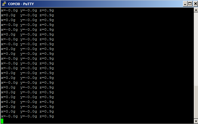
And here is the screen shot of the output of the PSoC FreeRTOS with the kit sitting on my desk…. the output is about 1G down (which make sense)

PSoC FreeRTOS: Output of Kionix KXTJ2-1009 Accelerometer

As always you can git this PSoC FreeRTOS project at the IoT Expert GitHub site or git@github.com:iotexpert/PSoC-FreeRTOS-Examples.git

Topic Description
FreeRTOS: A PSoC4 FreeRTOS Port An introduction to making FreeRTOS work on PSoC 4
FreeRTOS PSoC Examples Using multiple tasks in FreeRTOS
FreeRTOS Queue Example Using a queue to communicate between tasks
PSoC 6 FreeRTOS - The First Example Booting FreeRTOS on PSoC 6
FreeRTOS Binary Semaphore An first example of a binary semaphore
FreeRTOS Binary Semaphore (Part 2) Removing polling in the UART Task
FreeRTOS Counting Semaphore An example using a counting semaphore
PSoC FreeRTOS Reading I2C Sensors with a shared I2C Bus
PSoC FreeRTOS Task Notify A light weight scheme to replace Semaphores
PSoC FreeRTOS Task Notification Values A very light weight method to transfer one word of information into a task
PSoC FreeRTOS Counting Semaphore

Summary

The FreeRTOS Counting Semaphore is a simple extension of the binary semaphore that I talked about in the last two articles (PSoC Binary Semaphore, PSOC Binary Semaphore Part Two).  Simply put, the semaphore counts up when “set” and counts down when “get”.  When it is 0, the task that tried to “get” it is paused until some other task “set”s it.  There are a number of uses of the the counting semaphore including:

  • One or more producers tasks create events and one or more consumers tasks consume those events.  The semaphore counts the events
  • The semaphore represents one or more identical resources.  When you need that resource you take the flag, use the resource, then give the flag back. (e.g. identical blocks of scratch memory)

As I worked on this article I was looking around the internet for good examples, that would visibly demonstrate the counting semaphore.  There are a number of examples out there including, the dining philosophers, the line of bathrooms, the librarian but they all feel somewhat contrived.  The other thing that I realized as I looked around is that there are a bunch of different names for exactly the same thing, that is getting and setting the semaphore.  Those names include at least:

  • Signal/Wait
  • P/V
  • Give/Take
  • Set/Get

FreeRTOS Counting Semaphore Danger

There are a number of scenarios that can cause you much pain with threaded RTOS programming and semaphores.  Two of those cases are circular deadlocks and priority inversion.

The circular deadlock occurs when A depends on B who depends on C who depends on A.  If your program finds itself in this state, you will have a deadlock, which is almost certainly a highly-not-good thing.  A variation of the circular deadlock occurs when you have multiple threads that are dependent on a pool of shared resources and you end up with the scenario where each threads only has one of the resource that its needs (e.g. it requires 2 of the resources to get a job done).  Each thread is then stopped, and waiting for one of the other threads to release the resource.

The other problem that can occur (and be difficult to debug) is called priority inversion.  This can occur when a lower priority thread gets access to a scarce shared resource.  And, a higher priority thread ends up waiting for that shared resource.  This scenario effectively gives the lower priority task a higher priority.

PSoC FreeRTOS Counting Semaphore Example

My example is simply to have one task (called countingSemaphore)  which is consuming events and multiple places that are creating events.  When there are events available, the countingSemaphore task will just printout the number of events, decrement a.k.a. take the semaphore, then loop back.  I start by copying the project “4-Binary-Semaphore” and creating a new project called “5-Counting-Semaphore”.

To make this work, I first declare a global variable to hold the counting semaphore.

SemaphoreHandle_t countingSemaphore;

Then I initialize it in main

countingSemaphore = xSemaphoreCreateCounting(5,0); // Max=5 - Initial=0

Create the counting semaphore task

    /* To print when the counting semaphore is taken */
    xTaskCreate(
        countingSemaphore_Task,       /* Task function */
        "countsema",          /* Task name (string) */
        0x100,           /* Task stack, allocated from heap */
        0,               /* No param passed to task function */
        1,               /* Low priority */
        0 );

I make the task that will take the semaphore, then print the semaphore count, then start again.

void countingSemaphore_Task(void *arg)
{
   (void)arg;
    char buff[16];
    while(1)
    {
        xSemaphoreTake(countingSemaphore,portMAX_DELAY);
        sprintf(buff,"Count = %d\n",(int)uxSemaphoreGetCount( countingSemaphore ));
        UART_UartPutString(buff);
    }
}

Lastly I add the ability to “create events” by making the 1,2,3 keyboard keys create 1,2,3 events (a.k.a. set the semaphore 1,2,3 times)

         case '1':
                    xSemaphoreGive(countingSemaphore);
            break;
            
            case '2':
                    xSemaphoreGive(countingSemaphore);
                     xSemaphoreGive(countingSemaphore);
            break;

            case '3':
                xSemaphoreGive(countingSemaphore);
                xSemaphoreGive(countingSemaphore);
                xSemaphoreGive(countingSemaphore);
            break;

To test the program, I start up a terminal and:

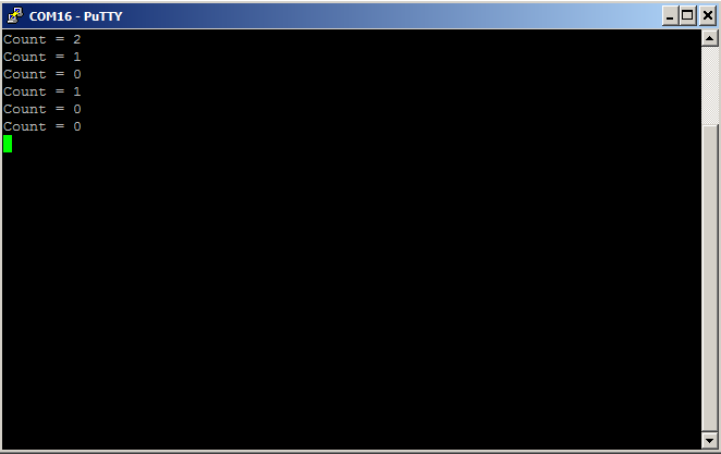
  • press ‘3’, which gives the semaphore 3 times in a row.  Then the countingSemaphore task consumes the “gives” with “takes” and prints out “2,1,0”
  • press ‘2+’, which gives the semaphore 2 times in a row.  Then the countingSemaphore task consumes the “gives” with “takes” and prints out “1,0”
  • press ‘1’, which gives the semaphore 1 time.  Then the countingSemaphore task consumes the “give” with “take” and prints out “0”

FreeRTOS Counting Semaphore Example

You can find this example on the IoT Expert GitHub website or git@github.com:iotexpert/PSoC-FreeRTOS-Examples.git

Topic Description
FreeRTOS: A PSoC4 FreeRTOS Port An introduction to making FreeRTOS work on PSoC 4
FreeRTOS PSoC Examples Using multiple tasks in FreeRTOS
FreeRTOS Queue Example Using a queue to communicate between tasks
PSoC 6 FreeRTOS - The First Example Booting FreeRTOS on PSoC 6
FreeRTOS Binary Semaphore An first example of a binary semaphore
FreeRTOS Binary Semaphore (Part 2) Removing polling in the UART Task
FreeRTOS Counting Semaphore An example using a counting semaphore
PSoC FreeRTOS Reading I2C Sensors with a shared I2C Bus
PSoC FreeRTOS Task Notify A light weight scheme to replace Semaphores
PSoC FreeRTOS Task Notification Values A very light weight method to transfer one word of information into a task
PSoC FreeRTOS Binary Semaphore (Part 2)

FreeRTOS Binary Semaphore – Update

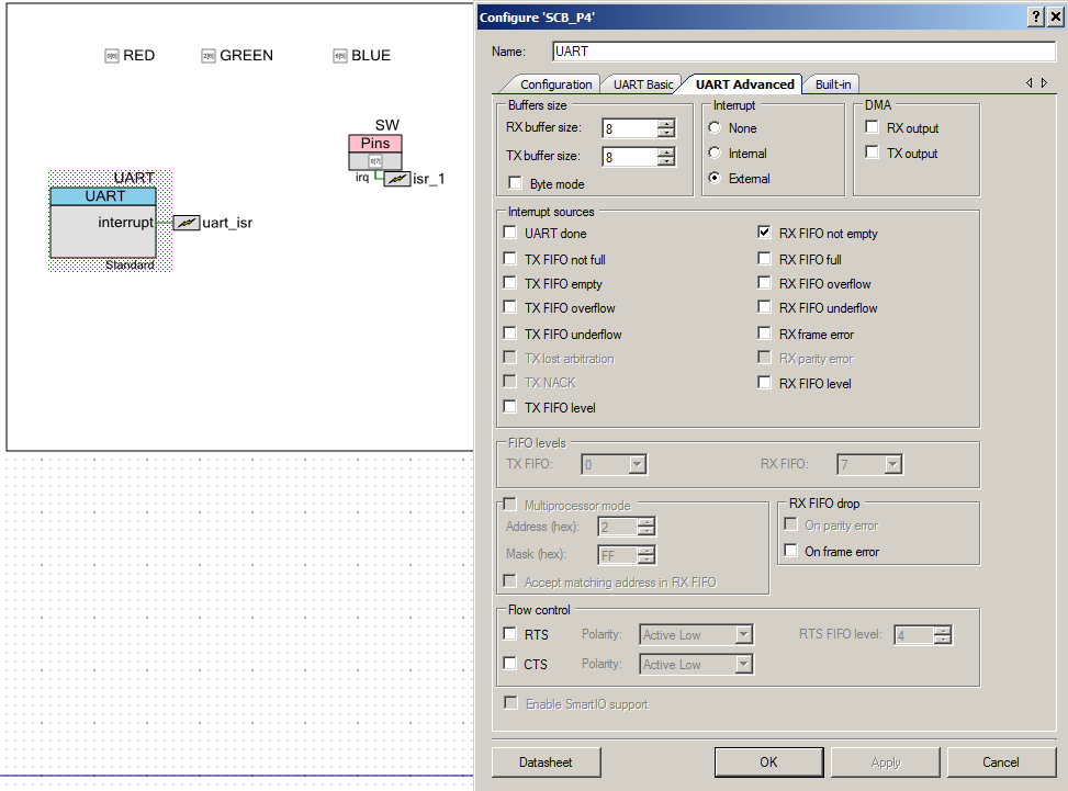
Last week I taught a class on WICED WiFi programming, which also uses and RTOS.  During that class I yelled at a number of people for not using the RTOS mechanisms that I was showing them.  Which got me thinking, that in all of the versions of the FreeRTOS example program that I have shown you, I have used a polling loop for handling the UART.  This was kind of bugging me (at very least it was inconsistent).  In order to fix this I decided use the FreeRTOS Binary Semaphore to fix the problems by:

  • Modifying the FreeRTOS Binary Semaphore schematic and adding the UART ISR
  • Add a FreeRTOS Binary Semaphore called “uartSemaphore” that I will set in the UART ISR
  • Turn on interrupt handling for the UART when there is one or more characters in the buffer
  • In the ISR turn off interrupts and set the “uartSemaphore”
  • In the UART task, wait for the “uartSemaphore”, then handle all of the characters, then turn the UART interrupt back on

First I copied the “4-BinarySemaphore” project and called it “4a-BinarySemaphore”.  Then I modified the schematic to support the UART ISR.

FreeRTOS Binary Semaphore UART Schematic

Then I create a new global variable called uartSemaphore.

SemaphoreHandle_t uartSemaphore;

In main I initialize the semaphore and install the ISR Handler.

    uartSemaphore = xSemaphoreCreateBinary();
    uart_isr_StartEx(uart_isr_Handler); 

In the ISR Handler, I clear the interrupt from the UART.  Originally I thought that I could just clear the pending interrupt, set the semaphore and return.  However, when I returned from the ISR, there were still characters in the receive FIFO, which made the UART immediately pend the interrupt.  This kept me from ever leaving the ISR.  To fix this I turn off all interrupt sources.  In the UART Task I will turn the interrupts back on when the FIFO is empty again.

CY_ISR(uart_isr_Handler)
{
    uint32_t cause;
    cause = UART_GetRxInterruptSource();
    UART_ClearRxInterruptSource(cause);
    UART_SetRxInterruptMode(0);
    xSemaphoreGiveFromISR(uartSemaphore,NULL);
    
}

Finally I modify the UART Task to

  • Line 77 Wait for  the semaphore (which is set in the ISR)
  • Line 78 Loop until there is nothing left in the FIFO (UARTGetChar() will return 0 when there is nothing left)
  • Line 124: Turn the UART Interrupts back on
void UART_Task(void *arg)
{
    (void)arg;
    static char buff[500];
    UART_Start();
    clearScreen();
    UART_UartPutString("Started UART\n\r");
    char c;
    Color_t tempColor;
    
	while(1) {
        
        xSemaphoreTake(uartSemaphore,portMAX_DELAY);
        while( (c = UART_UartGetChar()) )
        {
            switch(c)
            {
                case 'a':
                UART_UartPutString("Working\n\r");
                break;
                
                case 't':
                    UART_UartPutString("********************************************\n\r");
                    UART_UartPutString("Task          State   Prio    Stack    Num\n\r"); 
                    UART_UartPutString("********************************************\n\r");
                    vTaskList(buff);
                    UART_UartPutString(buff);
                    UART_UartPutString("*********************************************\n\r");
       
                break;
                    
                case 'r':
                    tempColor = RED;
                    if(xQueueSend(colorQueue,&tempColor,0) != pdTRUE)
                        UART_UartPutString("queue error\n\r");
                break;
                    
                case 'b':
                    tempColor = BLUE;
                    if(xQueueSend(colorQueue,&tempColor,0) != pdTRUE)
                        UART_UartPutString("queue error\n\r");
                break;

                case 'g':
                    tempColor = GREEN;
                    if(xQueueSend(colorQueue,&tempColor,0) != pdTRUE)
                        UART_UartPutString("queue error\n\r");
                break;
                        
                case 's':
                        xSemaphoreGive(switchSemaphore);
                break;
                        
                case 'c':
                        clearScreen();
                break;

            }
        }
        UART_SetRxInterruptMode(UART_INTR_RX_NOT_EMPTY);
    }
}

This is a fairly simple modification to my program which will save power (potentially), will save CPU cycles (for sure) and is generally much better inline with the RTOS philosophy.

Topic Description
FreeRTOS: A PSoC4 FreeRTOS Port An introduction to making FreeRTOS work on PSoC 4
FreeRTOS PSoC Examples Using multiple tasks in FreeRTOS
FreeRTOS Queue Example Using a queue to communicate between tasks
PSoC 6 FreeRTOS - The First Example Booting FreeRTOS on PSoC 6
FreeRTOS Binary Semaphore An first example of a binary semaphore
FreeRTOS Binary Semaphore (Part 2) Removing polling in the UART Task
FreeRTOS Counting Semaphore An example using a counting semaphore
PSoC FreeRTOS Reading I2C Sensors with a shared I2C Bus
PSoC FreeRTOS Task Notify A light weight scheme to replace Semaphores
PSoC FreeRTOS Task Notification Values A very light weight method to transfer one word of information into a task
PSoC FreeRTOS Binary Semaphore

Summary

In the previous FreeRTOS articles I have shown you how FreeRTOS threads work, and how to use a Queue to communicate data between threads.  In this article I will introduce you to another important RTOS concept, the Semaphore.  The Semaphore or in this case the FreeRTOS Binary Semaphore is a multi-threaded safe mechanism for signaling between threads.  I use the word “signal” because the word “semaphore” is an old-time word for a system of flags that were used to communicate between boats.  Here is a modern example of a flag semaphore, the Cypress Indycar winning finish line checkered flag earlier this year:

In RTOS, a binary semaphore is exactly the same thing as a checkered flag.  It is one thread waving another thread to indicate some specific message.  Specifically, what does the message flag mean?  It means whatever you define it to mean.  In this example, it will mean that a message can be printed on the screen.

In this article I will modify the queue example program from the previous article to add a semaphore that will:

  • Print a message when a specific key on the keyboard is pressed
  • Print a message when a mechanical button on the development kit is pressed

FreeRTOS Binary Semaphore Task

I will start by copying the “3-Queue” example and creating a new project called “4-Binary Semaphore”.  At the top of the program I will add a global variable of type “SemaphoreHandle_t” to hold my semaphore.  I use a global variable so that all of the threads will have access to the handle.

SemaphoreHandle_t switchSemaphore;

Before you can use the semaphore you must set it up.  At the start of main I initialize the semaphore:

switchSemaphore = xSemaphoreCreateBinary();

Now, I will create a new thread that will just sit and wait for the Semaphore flag.  On line 122, the xSemaphoreTake function will put that thread to sleep util one of the other threads has “given” the signal using the xSemaphoreGive function.  When that occurs, I print out the message and then loop back around and wait again.

void semaphore_Task(void *arg)
{
    (void)arg;
    while(1)
    {
        
        xSemaphoreTake(switchSemaphore,portMAX_DELAY);
        UART_UartPutString("Taken Switch Semaphore\n");
    }
}

Giving the FreeRTOS Binary Semaphore

Inside of the “UART_Task” on line 107, when the ‘s’ key is pressed, wave the FreeRTOS Binary Semaphore Flag… actually “give” the semaphore.  When this happens the “semaphore_Task” wakes up and prints out the message.

            case 's':
                    xSemaphoreGive(switchSemaphore);
            break;

With Semaphores there is an annoying level of inconsistency in the language.  Sometimes (as in FreeRTOS) it is “give/take” in WICED it is “set/get”, but they mean the same thing.

Using a Semaphore: Interrupt Service Routine

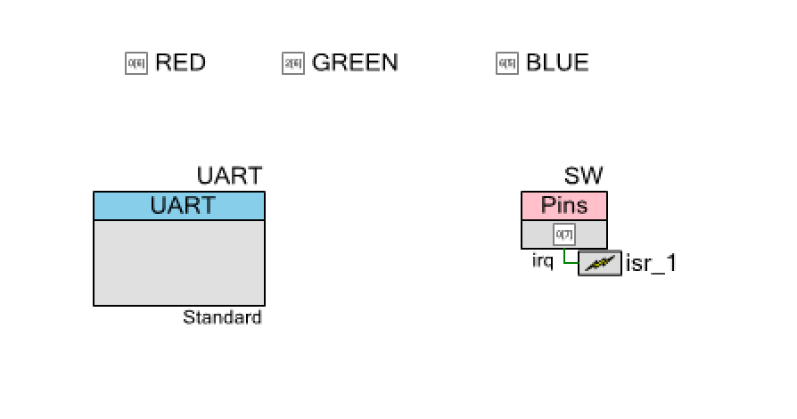
It is a very good practice to minimize the amount of work done inside of an interrupt service routine.  The FreeRTOS binary Semaphore is the perfect tool for achieving that objective.  When an interrupt occurs, set the semaphore flag then let the RTOS take care of the rest.  To show this example I add a digital input pin to the schematic and attach it to an interrupt.

FreeRTOS Binary Semaphore Schematic

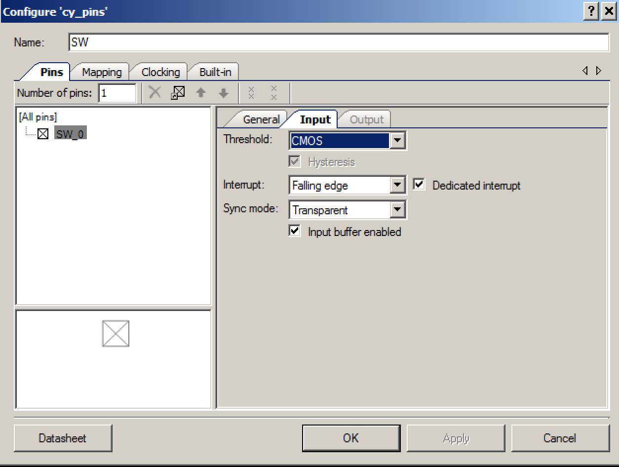
The pin is configured to trigger the interrupt on a falling edge (the switch on the board is active low).

Digital Input Pin Configuration

Now I create an ISR called “isr_1_Handler”.  All it does is clear the pin interrupt and then give the semaphore.  The only trick is that the FreeRTOS Binary Semaphore has a different give function for use inside of ISR.  In general, the FreeRTOS API adds “FromISR” onto the API to indicate that it is safe to use inside of an ISR.

CY_ISR(isr_1_Handler)
{
    SW_ClearInterrupt();
    xSemaphoreGiveFromISR(switchSemaphore,NULL);
}

The last thing to add is at the start of main I install the interrupt handler.

   isr_1_StartEx(isr_1_Handler);

Now when you press the mechanical switch on the devkit, you will get the message that the FreeRTOS Binary Semaphore has been set.

In the next article I will show you another type of semaphore, the counting semaphore.

Topic Description
FreeRTOS: A PSoC4 FreeRTOS Port An introduction to making FreeRTOS work on PSoC 4
FreeRTOS PSoC Examples Using multiple tasks in FreeRTOS
FreeRTOS Queue Example Using a queue to communicate between tasks
PSoC 6 FreeRTOS - The First Example Booting FreeRTOS on PSoC 6
FreeRTOS Binary Semaphore An first example of a binary semaphore
FreeRTOS Binary Semaphore (Part 2) Removing polling in the UART Task
FreeRTOS Counting Semaphore An example using a counting semaphore
PSoC FreeRTOS Reading I2C Sensors with a shared I2C Bus
PSoC FreeRTOS Task Notify A light weight scheme to replace Semaphores
PSoC FreeRTOS Task Notification Values A very light weight method to transfer one word of information into a task
PSoC 6 FreeRTOS – The First Example

Summary

In the previous article(s) I have been writing about using FreeRTOS on PSoC 4 development kits.  The other day a friend of mine in Kentucky sent me a note asking about PSoC6, so here it is.  PSoC 6.  In this article I will write about the first PSoC 6 FreeRTOS example, obviously, the blinking LED.  In this article I will also get to show off the Type-C connector on the new CY8CKIT-062-BLE Devkit.

Create PSoC 6 FreeRTOS Project

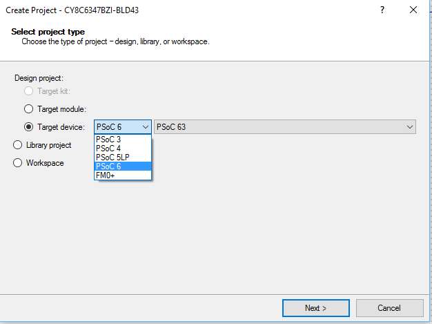
To get this whole thing going, create a new PSoC 6 project in PSoC Creator.  Because the PSoC 6 is still in early release, you will need the secret key to get it going in PSoC6 Creator (which you can find out from the Early Access Program).  But, when you know the key, you will get something that we have all been waiting for, the ability to create a PSoC 6 project.

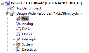
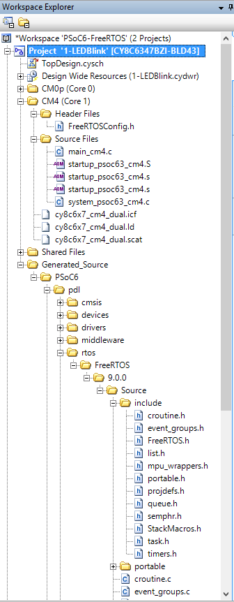
Once you have a new project (which I already renamed 1-LEDBlink) you can look at it in the Workspace Explorer where you will see the normal PSoC things, Schematic, Pins, Analog, etc.  So far, so good.

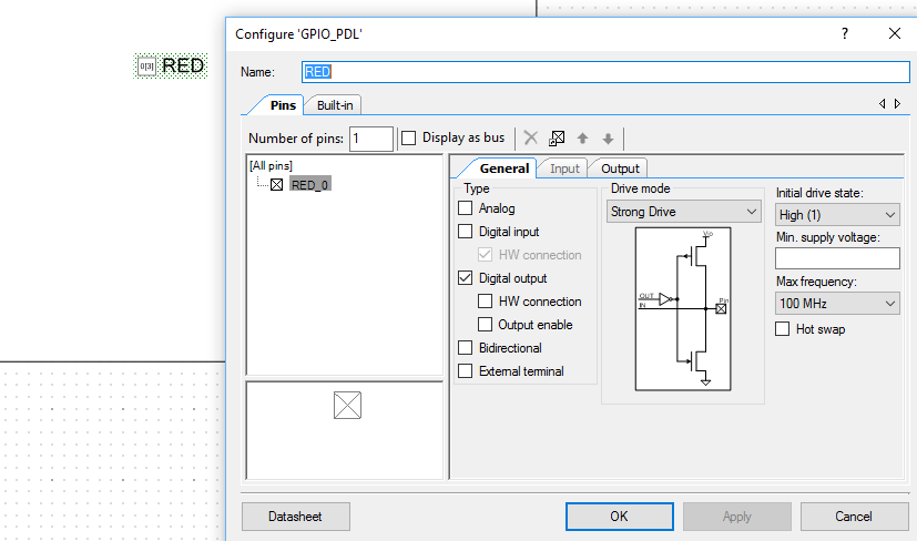
Next I click on then TopDesign.sch, then add a digital output pin.  That looks and feels familiar to all of you PSoC people out there.

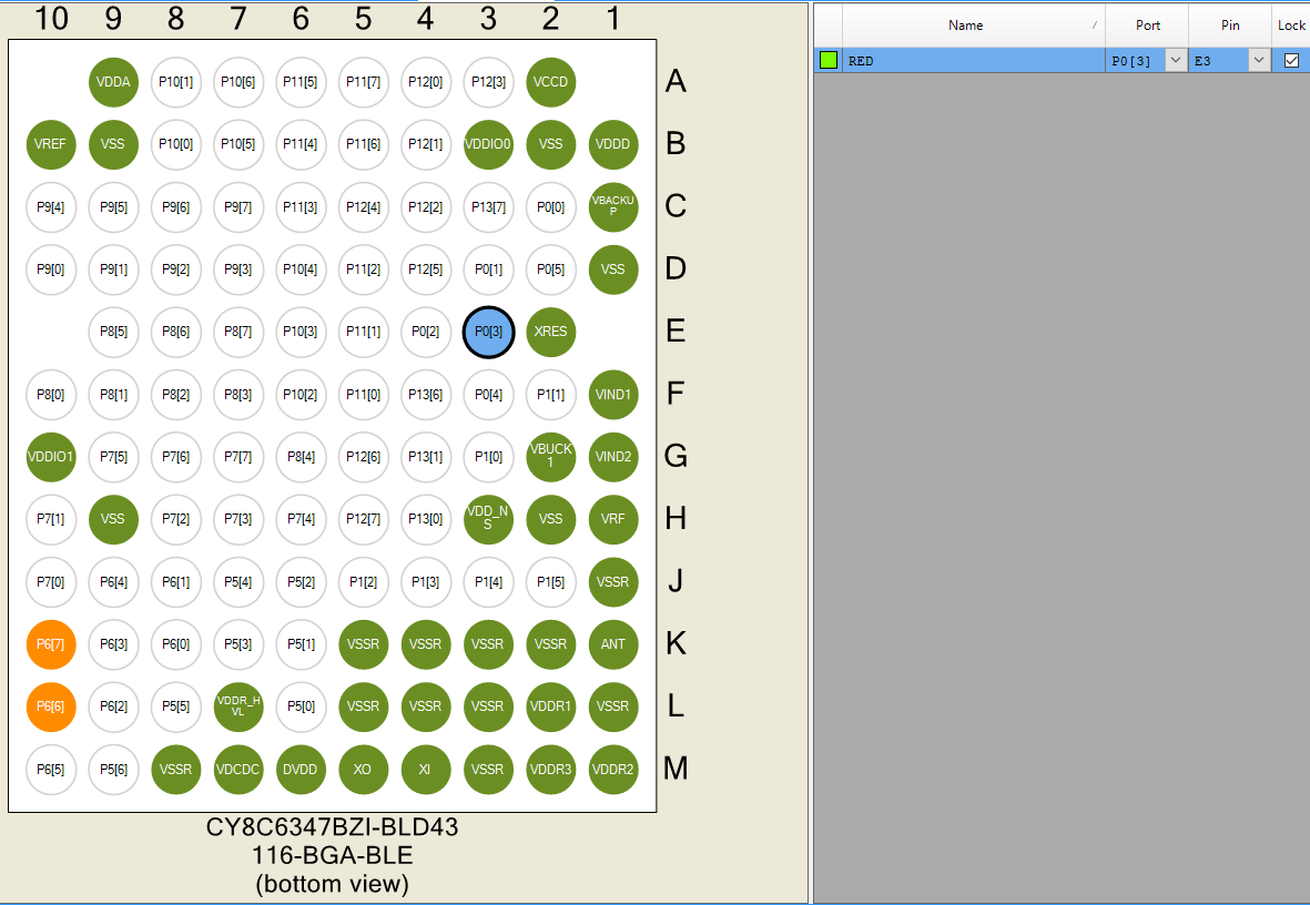
Next I assign the pin to “P0[3]” on the Pins tab.  Wow, that tiny little CSP has a boatload of pins, and yes this chip can do a bunch of things.

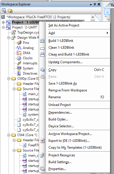
Now for some new stuff.  I want to have FreeRTOS included in my project.  In the PSoC 4 family you need to download it, add paths to your project etc. Read about it here.  Instead of doing that, you can edit the “Build Settings” by right clicking on the project.

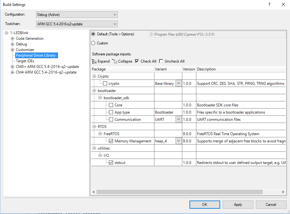
Then on the build settings menu, pick Peripheral Driver Library (more on this later).  On the PDL screen you can click to add “FreeRTOS” and you can pick out the memory management scheme (in this case I picked heap_4).

When you generate application, PSoC Creator will copy FreeRTOS into your project generated source, and give you a default FreeRTOSConfig.h (see it in the Header Files for the CM4)

PSoC Creator gives you a pretty generic FreeRTOSConfig.h file, with some of stuff hooked up (like the clock frequency).  This file is copied into your project.  Once that is done, you own it, and all of the changes to it.

#include "cy_device_headers.h"


#define configUSE_PREEMPTION                    1
#define configUSE_PORT_OPTIMISED_TASK_SELECTION 0
#define configUSE_TICKLESS_IDLE                 0
#define configCPU_CLOCK_HZ                      cy_delayFreqHz
#define configTICK_RATE_HZ                      1000u
#define configMAX_PRIORITIES                    7
#define configMINIMAL_STACK_SIZE                128
#define configMAX_TASK_NAME_LEN                 16
#define configUSE_16_BIT_TICKS                  0
#define configIDLE_SHOULD_YIELD                 1
#define configUSE_TASK_NOTIFICATIONS            1
#define configUSE_MUTEXES                       0
#define configUSE_RECURSIVE_MUTEXES             0
#define configUSE_COUNTING_SEMAPHORES           0
#define configQUEUE_REGISTRY_SIZE               10
#define configUSE_QUEUE_SETS                    0
#define configUSE_TIME_SLICING                  0
#define configUSE_NEWLIB_REENTRANT              0
#define configENABLE_BACKWARD_COMPATIBILITY     0
#define configNUM_THREAD_LOCAL_STORAGE_POINTERS 5

/* Memory allocation related definitions. */
#define configSUPPORT_STATIC_ALLOCATION         0
#define configSUPPORT_DYNAMIC_ALLOCATION        1
#define configTOTAL_HEAP_SIZE                   10240

The other thing that Creator does is hookup the necessary interrupt vectors (so that FreeRTOS will run)

/* Definitions that map the FreeRTOS port interrupt handlers to their CMSIS
standard names - or at least those used in the unmodified vector table. */
#define vPortSVCHandler     SVC_Handler
#define xPortPendSVHandler  PendSV_Handler
#define xPortSysTickHandler SysTick_Handler

Now you have a project setup, and template files for everything… including the CM0p.  After the chip turns on and the boot sequence is complete, it jumps to the main in the file main_cm0p.c.  That default version of that file just turns on the CM4.

/* ========================================
 *
 * Copyright YOUR COMPANY, THE YEAR
 * All Rights Reserved
 * UNPUBLISHED, LICENSED SOFTWARE.
 *
 * CONFIDENTIAL AND PROPRIETARY INFORMATION
 * WHICH IS THE PROPERTY OF your company.
 *
 * ========================================
*/
#include "project.h"

int main(void)
{
    __enable_irq(); /* Enable global interrupts. */
    /* Enable CM4.  CY_CORTEX_M4_APPL_ADDR must be updated if CM4 memory layout is changed. */
    Cy_SysEnableCM4(CY_CORTEX_M4_APPL_ADDR); 

    /* Place your initialization/startup code here (e.g. MyInst_Start()) */

    for(;;)
    {
        /* Place your application code here. */
    }
}

/* [] END OF FILE */

Finally, the file main_cm4.c contains your program.

On lines 3-6 I just create a function which locks the MCU if there is a memory allocation failure inside of the FreeRTOS.

Lines 8-17 is a FreeRTOS task to blink the LED.  Notice that the old PSoC 4 functions pin_Write() and pin_Read() are now replaced with PDL versions of those functions.

Lastly, lines 23-24 create the LED task and launch the RTOS.

#include <project.h>

void vApplicationStackOverflowHook(TaskHandle_t *pxTask, signed char *pcTaskName )
{
    while(1);
}

void ledTask(void *arg)
{
    (void)arg;
    
    while(1)
    {
        Cy_GPIO_Write(RED_PORT,RED_NUM,!Cy_GPIO_ReadOut(RED_PORT,RED_NUM));
        vTaskDelay(500);
    }
}

int main(void)
{
    __enable_irq(); /* Enable global interrupts. */

    xTaskCreate( ledTask, "LED Task",400,0,1,0);
    vTaskStartScheduler();

    while(1);
}

Program PSoC 6 FreeRTOS Project

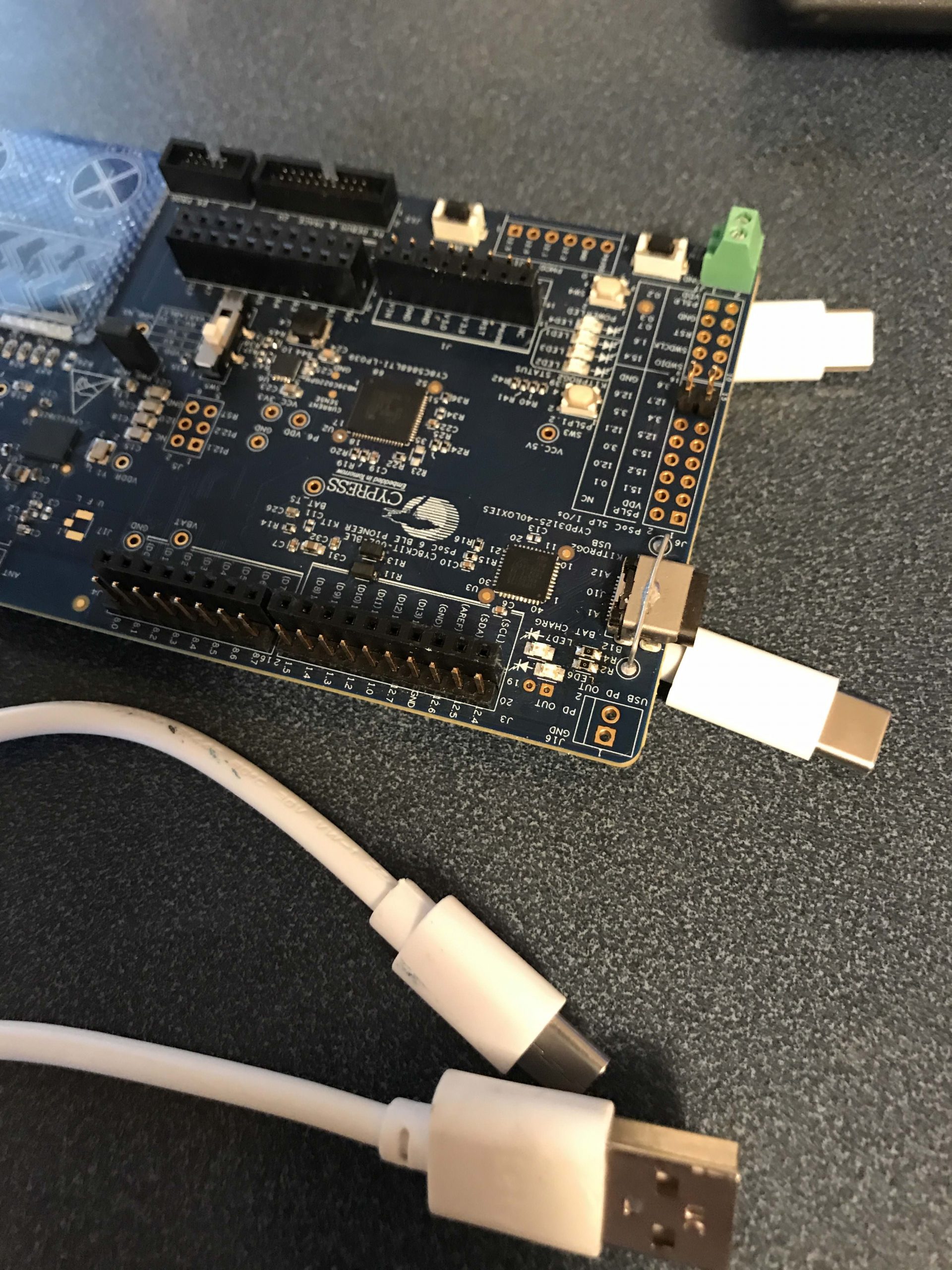
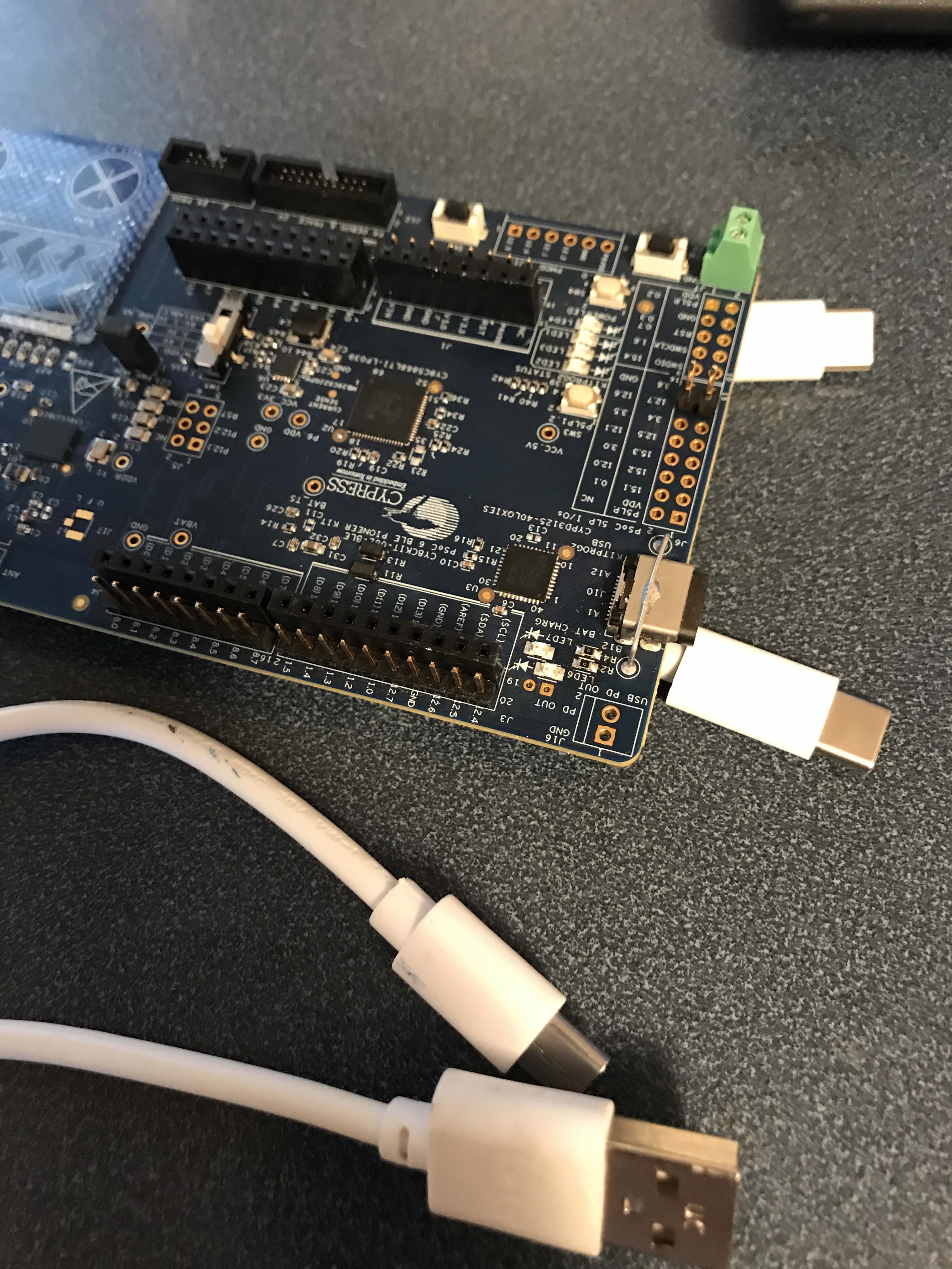
Now that we have firmware.  It is time to program the devkit.  One thing that I think is cool is that the devkit is the first (of ours) to have Type-C on the devkit (I wonder if it is the first in the Industry?).  We provide a Type-A to Type-C cable so you can keep rolling if you haven’t switched over to Type-C, but as I have a new Mac with only Type-C ,I use a Type-C to Type-C cable.PSoC 6 Type-C

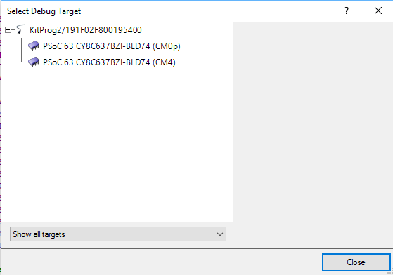
When you click program, PSoC Creator brings up the window asking you which core is the debug target.  In this case it doesn’t matter as you are programming a hex file with both the CM0+ and the CM4 code in it (remember they are shared memory).  So, I pick CM4 and let it rip.

Program PSoC 6 FreeRTOS Project

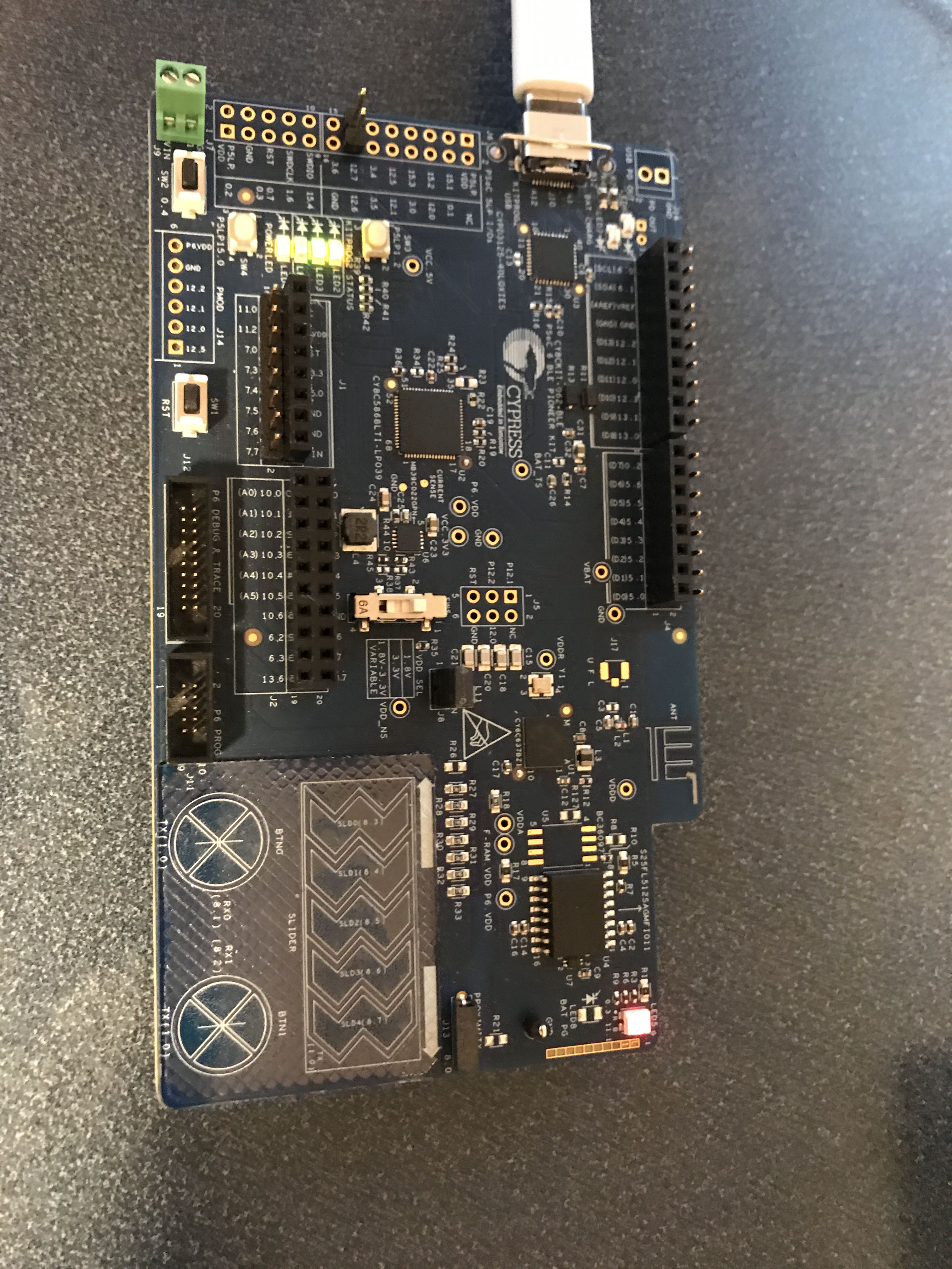
It is alive!  Amazing a dual core CM4/CM0 PSoC 6 FreeRTOS can blink the LED… how cool is that? PSoC6 FreeRTOS Blinking LED

In the next several articles I will be switching back and forth between the PSoC 4 & PSoC 6 FreeRTOS projects.

If you have something you are interested in please leave a comment and maybe I’ll build it for you.

Topic Description
FreeRTOS: A PSoC4 FreeRTOS Port An introduction to making FreeRTOS work on PSoC 4
FreeRTOS PSoC Examples Using multiple tasks in FreeRTOS
FreeRTOS Queue Example Using a queue to communicate between tasks
PSoC 6 FreeRTOS - The First Example Booting FreeRTOS on PSoC 6
FreeRTOS Binary Semaphore An first example of a binary semaphore
FreeRTOS Binary Semaphore (Part 2) Removing polling in the UART Task
FreeRTOS Counting Semaphore An example using a counting semaphore
PSoC FreeRTOS Reading I2C Sensors with a shared I2C Bus
PSoC FreeRTOS Task Notify A light weight scheme to replace Semaphores
PSoC FreeRTOS Task Notification Values A very light weight method to transfer one word of information into a task
PSoC FreeRTOS Queue Example

Summary

In the previous article I talked about getting FreeRTOS running on the PSoC, then creating two threads (one for a blinking LED and one for a UART command processor).  In this article I will add the ability to change which LED is blinking (the board has a tricolor RGB LED) by pressing a key on the keyboard.  Specifically ‘r’ for Red, ‘b’ for Blue and ‘g’ for Green.  In order for this to happen you will need to make the UART thread talk to the LED thread.  I will implement this with the FreeRTOS Queue mechanism.

FreeRTOS Queue

Using an RTOS like FreeRTOS is a great tool for reducing the complexity of your programs.  This is very useful when your MCU supports bigger more complicated programs.  However, using multiple threads of execution also creates problems. One of the poster children for threading problems is shared memory.

FreeRTOS uses a shared memory model.  Meaning, all of the threads in your program share the same address space and have access to all of the memory.  This means that one possible technique for communicating between threads would be to declare a global variable, which both threads have access to.

For example, you could declare a variable called “uint32_t ledColor” and have the the LED Thread read the variable to determine which LED to blink.  Then the UART thread could write the variable to set which LED is blinking.  Well maybe this isn’t such a good idea.  There are at least (and maybe more) things that can go wrong.

  • The compiler doesn’t know that there are multiple threads.  As a result, the variable may or may not always be in the RAM, it could be allocated for significant amounts of time into a register.  This means that one thread might write the RAM, and the other thread might not realize that it has changed because it is living in a register (this could be solved with the volatile keyword)
  • If instead of an “uint32_t” it was a “struct”, you could easily end up with a context switch while you had only partially written, or partially read the memory.
  • By using a variable, you will find yourself in the position of constantly polling the variable to find out if it had changed.

A better way to solve this problem is to use a FreeRTOS queue.  You can think of the queue as an array in the memory with a head and a tail.  You can insert new items into the tail of the queue, and you can remove them from the head of the queue.  The FreeRTOS queue makes sure that you do this “safely”, meaning you have complete transferred in or out before another thread can take over.  The FreeRTOS queue also makes sure that you don’t try to insert into a queue that is full, or remove from a queue that is empty by providing a mechanism to “block” your thread until it is either full/empty.

To use a queue you first

  1. Create a new queue with the FreeRTOS queue function xQueueCreate().  You need to tell it how many items are in the queue and how big the items are so that it can reserve space in the FreeRTOS heap to hold the items that you put in the queue.
  2. Next, Task1 can insert into the queue with the FreeRTOS queue function xQueueSend.  If there is room in the queue, FreeRTOS will memcpy your item into the head of the queue and then move down the tail pointer.  If there is no room it will either block your thread and wait until there is room in the queue, or it will return an error.
  3. Task2 can then receive from the queue with the FreeRTOS queue function xQueueReceive().  If there is something in the queue, it will memcpy from the queue into memory inside of your task, then move the tail pointer.  If there is nothing in the queue you can set it to either block your thread and wait, or return an error.


FreeRTOS Queue Example

Modify the project

I start the implementation process by copying the UART-Thread project to a new project called “Queue” and then adding the GREEN and BLUE LEDs to my schematic.

PSoC FreeRTOS Queue Example Project

Then I create a new type called “Color_t” which will represent the list of possible colors.  This is the “item” that I will add/remove from the queue.  Next I declare a global variable “QueueHandle_t” which is a data structure which FreeRTOS uses to keep track of the queue.  FreeRTOS can safely read and write this variable from multiple threads even though it is global.

typedef enum Color_t {
    RED,
    GREEN,
    BLUE
} Color_t;

QueueHandle_t colorQueue;

Before you can use a queue you must initialize it.  To do this call “xQueueCreate”.  This function takes two arguments

  • The number of elements that can be stored in the queue
  • How big the elements are in the queue.  You can store any “type” in the queue from a minimum of 1 word (32-bits) to something bigger, say a struct.  You are only limited by the memory on your MCU.
int main(void)
{
    CyGlobalIntEnable; /* Enable global interrupts. */
    
    setupFreeRTOS();
  
    colorQueue = xQueueCreate(1, sizeof(Color_t)); // 1 item queue that can hold colors

Next I will update the UART thread so that it can send a message to the queue.  If the queue is full I just printout that there is an error.  You could imagine that there are a number of ways that you might handle this error, but I opted for simple.  You can make this error happen if you press keys faster than 1x per 500ms.

            case 'r':
                tempColor = RED;
                if(xQueueSend(colorQueue,&tempColor,0) != pdTRUE)
                    UART_UartPutString("queue error\n\r");
            break;
                
            case 'b':
                tempColor = BLUE;
                if(xQueueSend(colorQueue,&tempColor,0) != pdTRUE)
                    UART_UartPutString("queue error\n\r");
            break;

            case 'g':
                tempColor = GREEN;
                if(xQueueSend(colorQueue,&tempColor,0) != pdTRUE)
                    UART_UartPutString("queue error\n\r");
            break;

The last thing to do is fixed the LED_Task to check for items in the queue.  If there is one, then turn off all of the LEDs and start blinking the new color.

void LED_Task(void *arg)
{
    (void)arg;
    
    Color_t currentColor = GREEN;
    
	while(1) {
        
        if(xQueueReceive(colorQueue,&currentColor,0) == pdTRUE)
            { RED_Write(1); BLUE_Write(1); GREEN_Write(1); }
        
        if(currentColor == RED)
            RED_Write(~RED_Read());
        else if (currentColor == BLUE)
            BLUE_Write(~BLUE_Read());
        else
            GREEN_Write(~GREEN_Read());
        
        vTaskDelay(500);
	}
}

If you have more FreeRTOS PSoC Examples that you are interested in please make a comment and maybe Ill create them.

As always, you can find the FreeRTOS PSoC Examples on the IoT Expert GitHub site or git@github.com:iotexpert/PSoC-FreeRTOS-Examples.git

Topic Description
FreeRTOS: A PSoC4 FreeRTOS Port An introduction to making FreeRTOS work on PSoC 4
FreeRTOS PSoC Examples Using multiple tasks in FreeRTOS
FreeRTOS Queue Example Using a queue to communicate between tasks
PSoC 6 FreeRTOS - The First Example Booting FreeRTOS on PSoC 6
FreeRTOS Binary Semaphore An first example of a binary semaphore
FreeRTOS Binary Semaphore (Part 2) Removing polling in the UART Task
FreeRTOS Counting Semaphore An example using a counting semaphore
PSoC FreeRTOS Reading I2C Sensors with a shared I2C Bus
PSoC FreeRTOS Task Notify A light weight scheme to replace Semaphores
PSoC FreeRTOS Task Notification Values A very light weight method to transfer one word of information into a task
FreeRTOS PSoC Examples (Part 1)

Summary: FreeRTOS PSoC Examples

Although in my last Article I said that I would get back to BLE Centrals this week, that turns out to not be the case because I have found myself down the FreeRTOS rabbit hole.  This week I will publish several FreeRTOS PSoC examples using PSoC 4 and PSoC 6.  I found myself here because I was working on BLE centrals on PSoC4, and I thought that I should try it on PSoC 6 to see how well it worked.  But, given the expansive capabilities of the chip, the reality is that PSoC 6 will almost certainly be programmed using an RTOS.  So, I decided to use FreeRTOS to try out the different features of PSoC 6.  But given that I don’t really know PSoC 6 yet … and I don’t really know FreeRTOS … I decided to experiment first on PSoC 4 examples first then once I understood what to with FreeRTOS, try the same things on PSoC 6.

Here is a video I took on Saturday in my office with three different PSoCs (PSoC 4 BLE, PSoC 4M, and PSoC 6) running FreeRTOS.  (yes my office looks like a tornado hit it).  The moral of the story is never underestimate the power of the blinking LED (to figure out what is going on).

In this article I will show FreeRTOS PSoC Examples:

  • Start with a single blinking LED Task
  • Add 2nd UART based command processor thread

In the upcoming articles I will add more FreeRTOS PSoC Examples:

  • Issue commands via a queue between the two threads
  • Interrupt processing & a Semaphore
  • Im not sure what else yet 🙂

Single Blinking LED

I start this process by following the instruction in my previous post to create a FreeRTOS example.  The project is straight forward, it does:

  • Installs the FreeRTOS vectors (lines 9-22)
  • Creates the LED Task (lines 41-48)
  • Starts the scheduler (line 50)
  • Runs the LED_Task until the end of time, blinking the LED (lines 25-33)
#include "project.h"
#include "FreeRTOS.h"
#include "timers.h"

extern void xPortPendSVHandler(void);
extern void xPortSysTickHandler(void);
extern void vPortSVCHandler(void);
#define CORTEX_INTERRUPT_BASE          (16)
void setupFreeRTOS()
{
    /* Handler for Cortex Supervisor Call (SVC, formerly SWI) - address 11 */
    CyIntSetSysVector( CORTEX_INTERRUPT_BASE + SVCall_IRQn,
        (cyisraddress)vPortSVCHandler );
    
    /* Handler for Cortex PendSV Call - address 14 */
	CyIntSetSysVector( CORTEX_INTERRUPT_BASE + PendSV_IRQn,
        (cyisraddress)xPortPendSVHandler );    
    
    /* Handler for Cortex SYSTICK - address 15 */
	CyIntSetSysVector( CORTEX_INTERRUPT_BASE + SysTick_IRQn,
        (cyisraddress)xPortSysTickHandler );
}


void LED_Task(void *arg)
{
    (void)arg;
    
	while(1) {
        RED_Write(~RED_Read());
        vTaskDelay(500);
	}
}

int main(void)
{
    CyGlobalIntEnable; /* Enable global interrupts. */
    
    setupFreeRTOS();
  
    /* Create LED task, which will blink the LED */
    xTaskCreate(
        LED_Task,       /* Task function */
        "LED Blink",    /* Task name (string) */
        200,            /* Task stack, allocated from heap */
        0,              /* No param passed to task function */
        1,              /* Low priority */
        0 );            /* Not using the task handle */
      
    vTaskStartScheduler();
    while(1); // get rid of the stupid warning
}

You can see the blinking LED in the video from above.

UART Thread

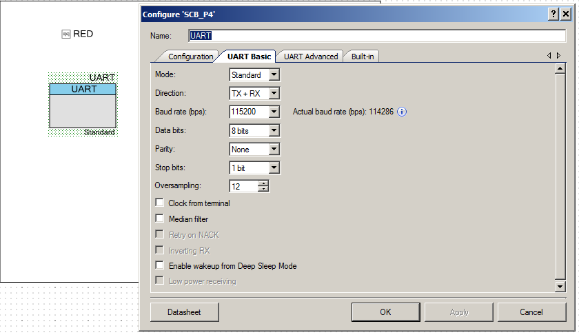
Once you have the blinking LED working, that means you have all of the environment setup etc… for some reason this always feels like a big step.  I then copy the BlinkingLED project and give it the name “UART-Thread”.  Then add a debugging UART to the schematic:

FreeRTOS PSoC Examples - PSoC Schematic

Now you can add the UART Thread to your project.  It is pretty simple:

  • Starts the UART
  • Gets a key from the keyboard (line 47)
  • If it is an ‘a’ it prints out “Working” (line 51)
  • If it is a ‘t’ it calls the function vTaskList which makes a dump of the process currently running (more on this later) (lines 54-60)
#include "project.h"
#include "FreeRTOS.h"
#include "task.h"
#include "queue.h"
#include "event_groups.h"
#include "timers.h"

extern void xPortPendSVHandler(void);
extern void xPortSysTickHandler(void);
extern void vPortSVCHandler(void);
#define CORTEX_INTERRUPT_BASE          (16)
void setupFreeRTOS()
{
    /* Handler for Cortex Supervisor Call (SVC, formerly SWI) - address 11 */
    CyIntSetSysVector( CORTEX_INTERRUPT_BASE + SVCall_IRQn,
        (cyisraddress)vPortSVCHandler );
    
    /* Handler for Cortex PendSV Call - address 14 */
	CyIntSetSysVector( CORTEX_INTERRUPT_BASE + PendSV_IRQn,
        (cyisraddress)xPortPendSVHandler );    
    
    /* Handler for Cortex SYSTICK - address 15 */
	CyIntSetSysVector( CORTEX_INTERRUPT_BASE + SysTick_IRQn,
        (cyisraddress)xPortSysTickHandler );
}


void LED_Task(void *arg)
{
    (void)arg;
    
	while(1) {
        RED_Write(~RED_Read());
        vTaskDelay(500);
	}
}

void UART_Task(void *arg)
{
    (void)arg;
    static char buff[500];
    UART_Start();
    UART_UartPutString("Started UART\n\r");
    char c;
    
	while(1) {
        c = UART_UartGetChar();
        switch(c)
        {
            case 'a':
            UART_UartPutString("Working\n\r");
            break;
            
            case 't':
                UART_UartPutString("********************************************\n\r");
                UART_UartPutString("Task          State   Prio    Stack    Num\n\r"); 
                UART_UartPutString("********************************************\n\r");
                vTaskList(buff);
                UART_UartPutString(buff);
                UART_UartPutString("*********************************************\n\r");
   
            break;
        }
        taskYIELD();
    }
}

int main(void)
{
    CyGlobalIntEnable; /* Enable global interrupts. */
    
    setupFreeRTOS();
  
    /* Create LED task, which will blink the LED */
    xTaskCreate(
        LED_Task,       /* Task function */
        "LED Blink",    /* Task name (string) */
        200,            /* Task stack, allocated from heap */
        0,              /* No param passed to task function */
        1,              /* Low priority */
        0 );            /* Not using the task handle */
   
    
    /* Create UART Task which will control the serial port */
    xTaskCreate(
        UART_Task,       /* Task function */
        "UART",          /* Task name (string) */
        0x400,           /* Task stack, allocated from heap */
        0,               /* No param passed to task function */
        1,               /* Low priority */
        0 );             /* Not using the task handle */
   
    vTaskStartScheduler();
    while(1);
}


Testing the project

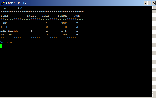
When I program the development kit, the LED starts blinking.  That is good.  Then I press ‘t’ which dumps out a table of the processes running.  The columns are

  • The name of the task
  • The state of the task (R-Running, B-Blocked, S-Suspended)
  • The priority (0-configMAX_PRIORITIES from FreeRTOSConfig.h)
  • The highwater mark of the stack usage of that thread.  In the UART thread I declared 0x400 (1024) so it appears I have used most of the RAM.
  • The task number

FreeRTOS PSoC Examples UART Serial Port

It is interesting that there are two tasks that I didnt create.  The FreeRTOS requires that there alway be some task, so it automatically creates an IDLE tasks which it runs when there is nothing else available to run.  It is possible to put the chip to sleep by adding to the IDLE task.  The other task is the Timer Service task which is what enables me to use the software delay (vTaskDelay).

If you have more FreeRTOS PSoC Examples that you are interested in please make a comment and maybe Ill create them.

As always, you can find the FreeRTOS PSoC Examples on the IoT Expert GitHub site or git@github.com:iotexpert/PSoC-FreeRTOS-Examples.git

Topic Description
FreeRTOS: A PSoC4 FreeRTOS Port An introduction to making FreeRTOS work on PSoC 4
FreeRTOS PSoC Examples Using multiple tasks in FreeRTOS
FreeRTOS Queue Example Using a queue to communicate between tasks
PSoC 6 FreeRTOS - The First Example Booting FreeRTOS on PSoC 6
FreeRTOS Binary Semaphore An first example of a binary semaphore
FreeRTOS Binary Semaphore (Part 2) Removing polling in the UART Task
FreeRTOS Counting Semaphore An example using a counting semaphore
PSoC FreeRTOS Reading I2C Sensors with a shared I2C Bus
PSoC FreeRTOS Task Notify A light weight scheme to replace Semaphores
PSoC FreeRTOS Task Notification Values A very light weight method to transfer one word of information into a task
FreeRTOS: A PSoC4 FreeRTOS Port

Summary

In my work life, I am working on some systems that will require more complicated firmware architectures built using real time operating systems.  As I need to get more familiar with RTOSs, I thought that I would go ahead and start using them in my PSoC 4 projects.  The logical one to start with is FreeRTOS.  In this article I will take you through the steps to create a PSoC4 FreeRTOS port.

  1. Introduce FreeRTOS
  2. Execute a PSoC4 FreeRTOS Port
  3. Create a PSoC4 FreeRTOS Test Project (the blinking LED)

FreeRTOS Background

FreeRTOS is a light weight, open-source, real time operating systems for embedded systems that was developed by RealTime Engineers.  Their basic business plan is to sell consulting and support services to semiconductor companies their customers.  All of the source code is available (mostly in plain C) and easy to use.  In addition there are ports to 35 MCUs (including all of the Cypress ARM chips).  FreeRTOS is frequently cited as the most popular embedded RTOS which is easy to understand as I have found it easy to use and very stable.

Execute a PSoC4 FreeRTOS Port

The port of FreeRTOS to PSoC4 is actually pretty trivial, once you figure it out.  But I suppose that is how things often go.  FreeRTOS comes preconfigured with a GCC version of an ARM Cortex-M0 port.  All that needs to be done is to hook the basic port to the correct PSoC4 systems.  There are generic porting instruction on the FreeRTOS site but these are my PSoC specific steps:

    1. Download FreeRTOS V9.0.0
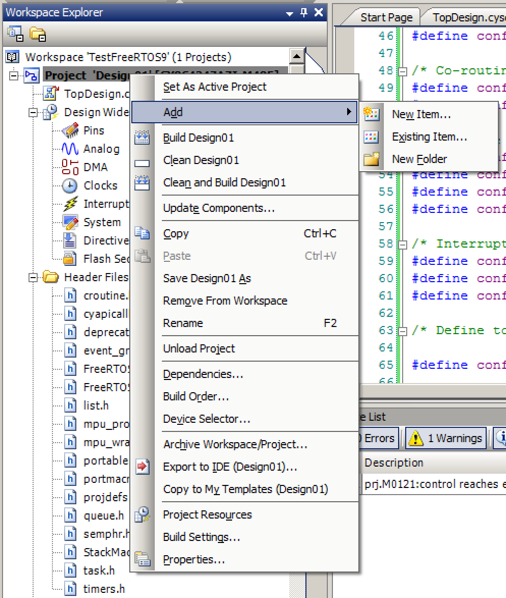
    2. Add the include directories “FreeRTOS/Source/include” and “FreeRTOS/Source/portable/GCC/ARM_CM0” to your project by right clicking on the project and editing “Build Settings…”  You should add those directories to the “Additional Include Directories”Configuring the PSoC 4 FreeRTOS build settings
    3. Right click on the project and “Add Existing Item” so that you can add the .c & .h files from FreeRTOS/Source/portable/GCC/ARM_CM0  to your projectAdd the PSoC4 FreeRTOS Files to Project
    4. Add the .c files from FreeRTOS/Source/ to your project
    5. Add the .h files from FreeRTOS/Source/include to your project
    6. Add “heap_1.c” (or which ever memory manager you want) from FreeRTOS/Source/portable/MemMang
    7. Create the “setupFreeRTOS” function to install the Interrupt Service vectors required by FreeRTOS.
extern void xPortPendSVHandler(void);
extern void xPortSysTickHandler(void);
extern void vPortSVCHandler(void);
#define CORTEX_INTERRUPT_BASE          (16)
void setupFreeRTOS()
{
    /* Handler for Cortex Supervisor Call (SVC, formerly SWI) - address 11 */
    CyIntSetSysVector( CORTEX_INTERRUPT_BASE + SVCall_IRQn,
        (cyisraddress)vPortSVCHandler );
 
    /* Handler for Cortex PendSV Call - address 14 */
	CyIntSetSysVector( CORTEX_INTERRUPT_BASE + PendSV_IRQn,
        (cyisraddress)xPortPendSVHandler );    
 
    /* Handler for Cortex SYSTICK - address 15 */
	CyIntSetSysVector( CORTEX_INTERRUPT_BASE + SysTick_IRQn,
        (cyisraddress)xPortSysTickHandler );
}

8. Create the FreeRTOSConfig.h First, add a new file called FreeRTOSConfig.h file to the project (right click on the project and “add new item”.  This file contains a bunch of CPP macros to setup FreeRTOS.  You can get this file by copy/pasting from the the linked website into your blank FreeRTOSConfig.h file.
9. Modify FreeRTOSConfig.h I made the following changes to the default configuration file:

// Add the PSOC Creator Macros for the PSoC4 Registers 
#include "project.h"
// PSoC Creator creates a #define macro for the clock settings from the DWR
#define configCPU_CLOCK_HZ ( ( unsigned long ) CYDEV_BCLK__SYSCLK__HZ )
// SysTick Defaults to 1ms
#define configTICK_RATE_HZ                      1000
#define configSUPPORT_STATIC_ALLOCATION   0
#define configSUPPORT_DYNAMIC_ALLOCATION  1
#define configTOTAL_HEAP_SIZE               10240
#define configAPPLICATION_ALLOCATED_HEAP 0
// During an assert just put into a busy wait
#define configASSERT ( x ) if( ( x ) == 0 ) { taskDISABLE_INTERRUPTS(); for( ;; ); }

Create a PSoC4 FreeRTOS Test Project

The example project is a simple blinked LED.  It starts with a “Task” function which I call LED_Task.  This just reads the current value of the RED Led pin, inverts it, and writes it back.  Then it does and RTOS delay of 500 ms.  The main look just turns on the interrupt system, initializes the RTOS, Creates the LED Task, then starts the scheduler.  The Scheduler will never return.

void LED_Task(void *arg)
{
    (void)arg;
 
        while(1) {
        RED_Write(~RED_Read());
        vTaskDelay(500);
        }
}
 
int main(void)
{
    CyGlobalIntEnable; /* Enable global interrupts. */
 
    setupFreeRTOS();
 
    /* Create LED task, which will control the intensity of the LEDs */
    xTaskCreate(
        LED_Task,       /* Task function */
        "LED Blink",    /* Task name (string) */
        200,            /* Task stack, allocated from heap */
        0,              /* No param passed to task function */
        1,              /* Low priority */
        0 );            /* Not using the task handle */
 
    vTaskStartScheduler();
}