Summary
Earlier this year I wrote an article about using the PSoC 4200M WDT Watch Dog Timers. In it I described a bunch of things that you could do with the PSoC 4200M WDT to help you time events, reset the part etc. Recently a user named JAGIR asked if I could generate interrupts slower than 2 seconds and have the PSoC 4200M in deep sleep. The answer to both of those questions is yes.
In order to make this work you need to “cascade” two WDTs together, something you can only do with firmware. I have updated my previous workspace with a new project called “LongDeepSleep” which you can “Git” on my GitHub website or you can “git@github.com:iotexpert/PSoC4-WDTExamples.git”
Configure the PSoC 4200M WDT Design
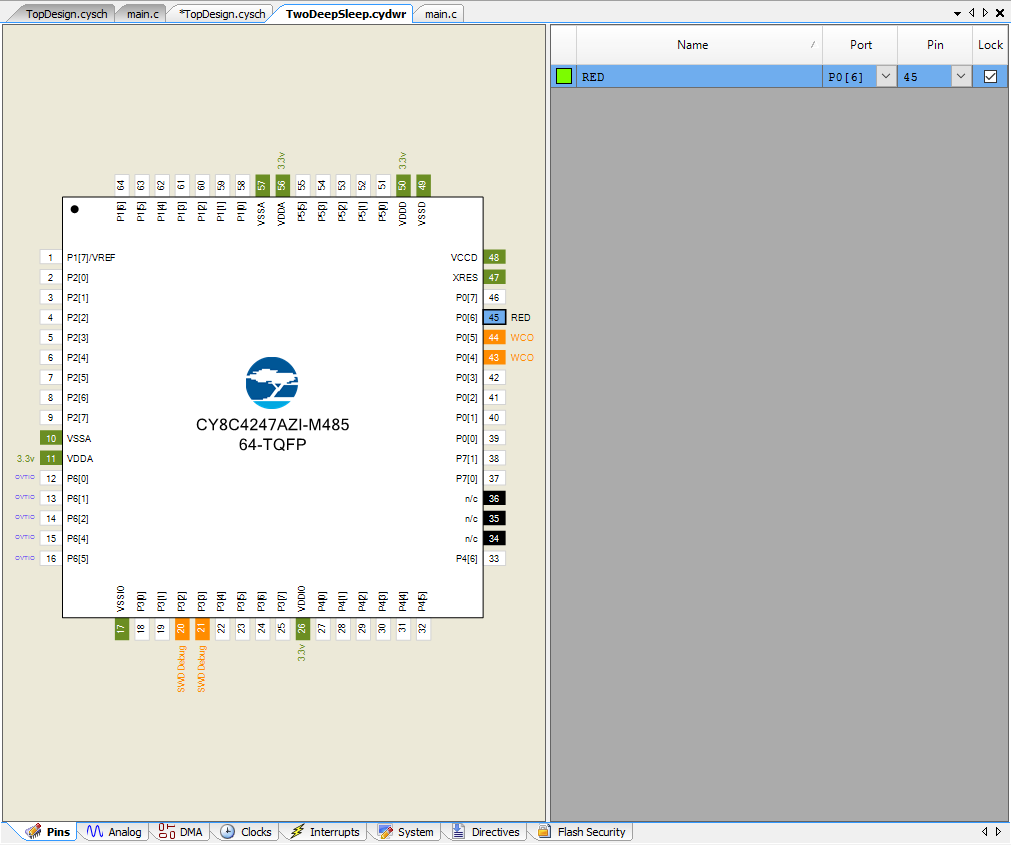
First add a digital output pin called “RED” to the schematic

Then assign it to P0[6]
Go to the clocks tab of the design wide resources. Then click on “Edit Clock”.
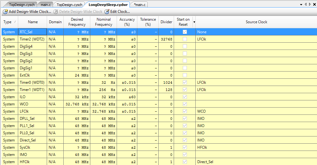
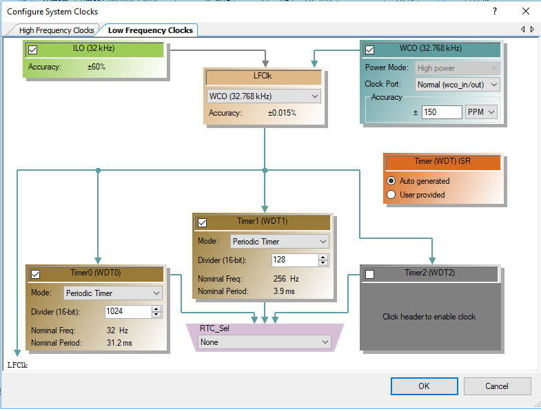
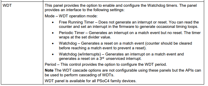
On the Low Frequency Clocks configuration page of the design wide resources turn on the two WDTs and setup the dividers.
System Reference Guide – PSoC 4200M WDT
All of the documentation for the PSoC 4200M WDT is in the “Low Frequency Clock aka cy_lfclk” of the system resources documentations.
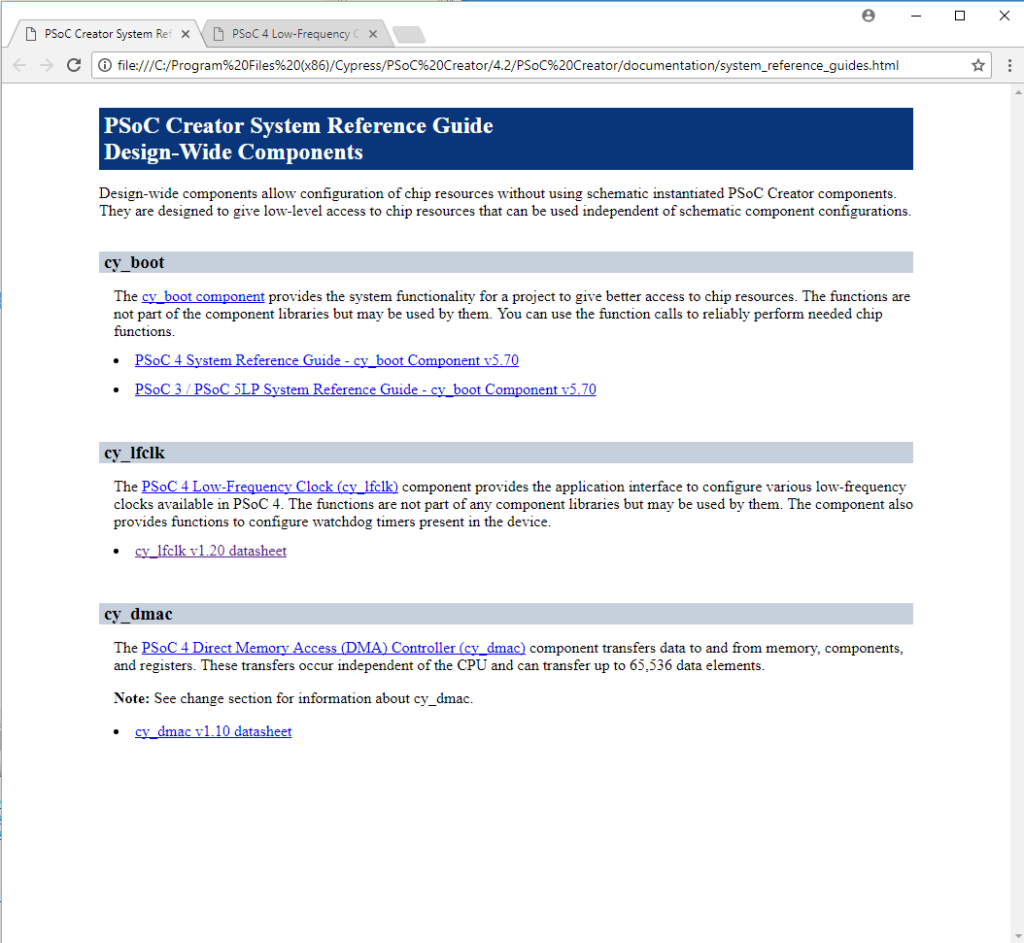
When you read a little bit down in the PSoC 4 Low Frequency clock documentation you will find “Note The EDT cascade options are not configurable using these panels but the APIs can be used to perform cascading of WDTs”
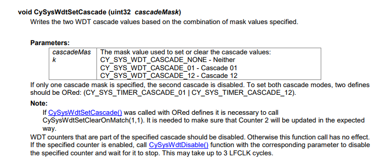
Then you search a little bit further down in the document and you will find the API CySysWDTSetCascade which will allow you to hook multiple 16-bit counters together to get 32 or more bits.
Write the PSoC 4200M WDT Firmware
The first example will blink the LED every 4 seconds. Remember from the configuration above it has a 32KHz input clock with a divider of 1024 on WDT0 and a divider of 128 on WDT1. That means you will get 32KHz / (1024 *128) = 0.25 Hz aka every 4 seconds.
#include "project.h"

void wdtCallback()
{
    RED_Write(~RED_Read());

}

int main(void)
{
    CyGlobalIntEnable; /* Enable global interrupts. */
    CySysWdtSetInterruptCallback(CY_SYS_WDT_COUNTER1,wdtCallback);
    CySysWdtSetCascade(CY_SYS_WDT_CASCADE_01);

    for(;;)
    {
        CySysPmDeepSleep();
    }
}
You can also get different delays by changing the dividers using firmware. In the example below it is 1Hz output.
#include "project.h"

void wdtCallback()
{
    RED_Write(~RED_Read());
}

int main(void)
{
    CyGlobalIntEnable; /* Enable global interrupts. */
    CySysWdtSetInterruptCallback(CY_SYS_WDT_COUNTER1,wdtCallback);
    CySysWdtSetCascade(CY_SYS_WDT_CASCADE_01);

    CySysWdtSetMatch(0,512);
    CySysWdtSetMatch(1,64);
    // Total divide = 512*64 = 32768

    for(;;)
    {
        CySysPmDeepSleep();
    }
}
2 Comments
Thank you, Alan, for writing this article. It will be very much helpful for other engineers like me.
As per my point of view writing match value for each timer would be much easier than setting divider in .cydwr file to calculate deep sleep interval.
And one more question, To implement deep sleep mode with the current consumption of uA I followed code but I did not get it, Will you please explain me about the use case of all 4 clock source(IMO, ECO, WCO. ILO). & why we are controling them before & after of deep sleep ?
The code snippet I used is:
/* Reduce ECO frequency to 3 MHz */
CySysClkWriteEcoDiv(CY_SYS_CLK_ECO_DIV8);
CySysClkEcoStop(); /* Shutdown ECO to save power */
CySysClkWcoStart(); /* Start the WCO clock */
CySysPmDeepSleep();
CySysClkSetLfclkSource(CY_SYS_CLK_LFCLK_SRC_WCO); /* LFCLK is now driven by WCO */
CySysClkWcoSetPowerMode(CY_SYS_CLK_WCO_LPM); /* Switch WCO to the low power mode after
CySysClkIloStop(); /* To stop ILo clock source */
CySysClkEcoStart(1); /* Start ECO clock to start BLE stack */
I am not totally sure where you found that block of code…. but… before I answered this comment I read which is a good Application Note on Power.
http://www.cypress.com/file/121271/download
There are two clock domains… the high speed clocks which are generated by 1) the ECO 2) the IMO 3) a pin. The CPU and high speed peripherals will use less power when they are clocked slower.
The low speed domain is driven by 1) the ILO or 2) the WCO …
I dont know if the chip uses less power with the WCO or the ILO. For sure if you are using the WCO your should turn off ILO.
Obviously you should turn off the IMO if you are running on an ECO.
I THINK that the chip comes out of deep sleep with the IMO running… and you need to turn the ECO back on to make the BLE work right… so when it comes out of deep sleep it turns on the IMO … then runs there until the ECO stabilizes.. then you switch to it.
In a BLE design you need the WCO to get the timing good enough to wakeup the chip in time for a connection interval.
The WCO low power mode just takes longer for the WCO to stabilize when the chip boots… after it boots you can go to the WCO low power.
I suppose I could try them…
Alan