Cypress Type-C Barrel Connector Replacement + Infineon Buck DC/DC (part 1)

Summary

In this article I will walk you through the first steps of building a complete Type-C power supply that will look like this:

The Project

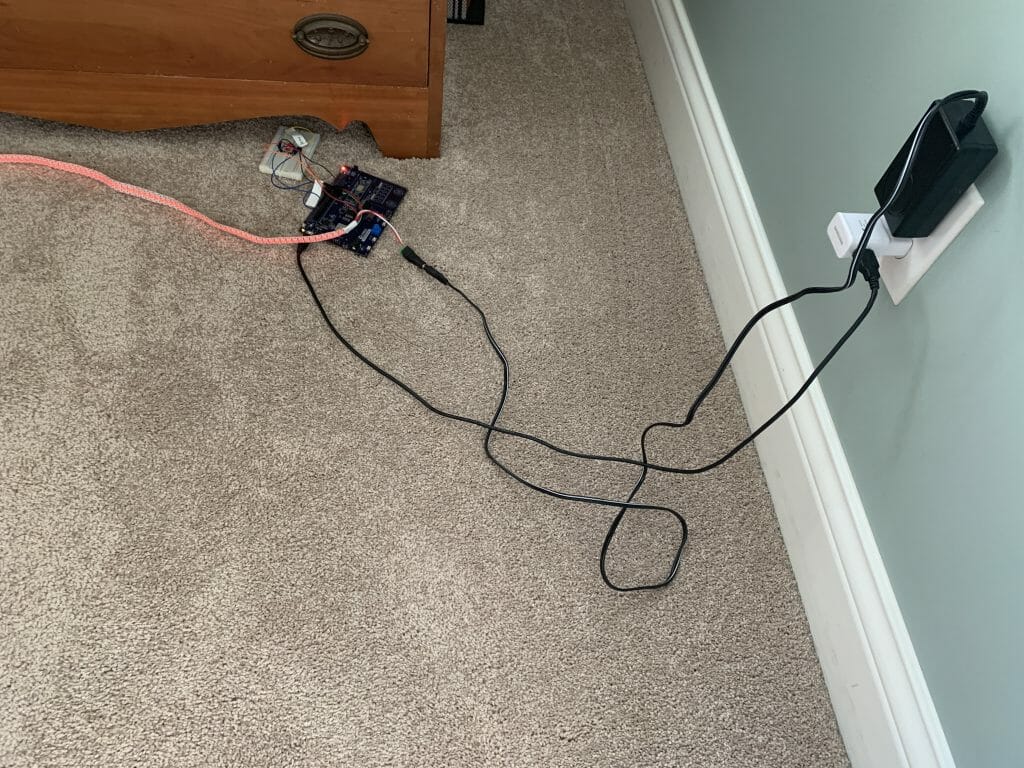
I have been working on a project that will drive several strings of WS2812 LEDs.  Specifically, a CapSense dimmable “IoT-ified” nightlight using a PSoC 6 attached to a CYW43012 attached to a string of WS2812 LEDs.   Right now, I have this thing built up with a development kit + a breadboard + 2 wall warts and it is sitting on the floor beside my bed.

When you see this picture, I’m sure that you are thinking.  “You are probably going to be sleeping on the floor beside your bed if you don’t do something better than that.”  And you would be right.  I know that I want a single PCB in a nice 3-d printed box that does all of this.  I also know that I want to use Type-C instead of a normal 12v wall wart.  When I started this I had only the vaguest ideas about how to turn Type-C into something that could drive a bunch of LEDs and a PSoC.  How much power do I need?  And at what voltages?  That seemed like the first question that needed answering.

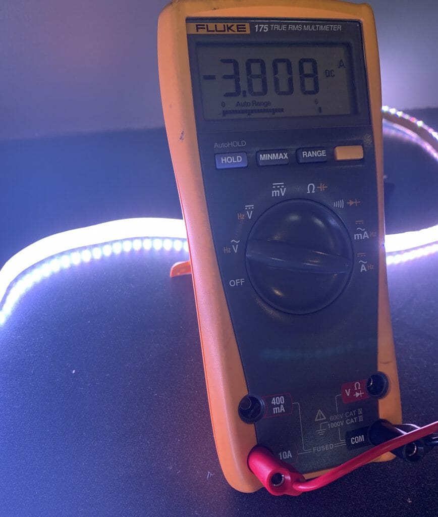
First, I put a meter on a string of 144 WS2812 LEDs.  Wow, 5V at ~4A when the LEDs are full on.  That is 20W per string… basically 30mA per WS2812.

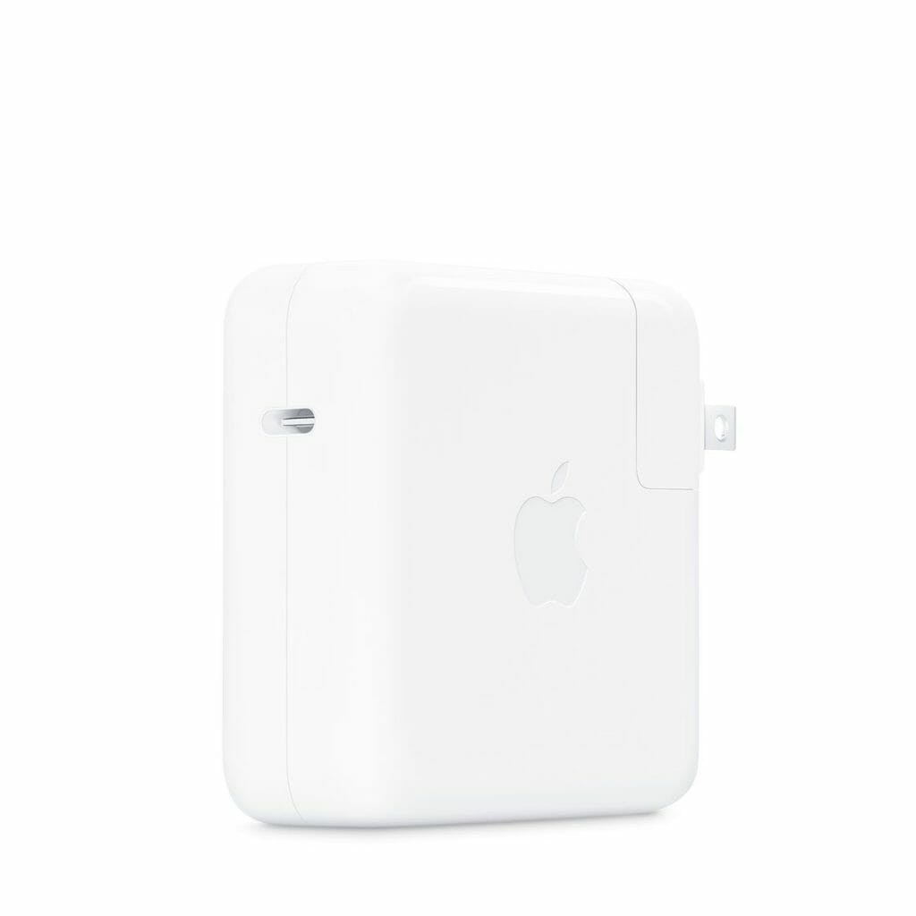
To make a board that can drive three strings of these LEDs I am going to require 3x20w + whatever the PSoC takes.  A bunch.  But where should I get this much power?  The answer is I am going to start with a laptop Type-C charger like this one from Apple (which I have several of)

The first/next question is, how do I tell the Apple adaptor what voltage/current I want?  It turns out that Cypress is the leader in Type-C chips and we make the perfect chip for this application.  It is called the CYPD3177-24LQXQ and is known colloquially as the EZ-PD™ Barrel Connector Replacement (BCR).  This is good because that is exactly what I want to do, replace a wall wart barrel with a Type-C.

Cypress CY4533 Development Kit

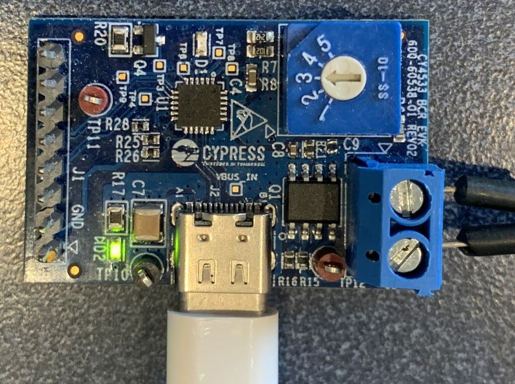
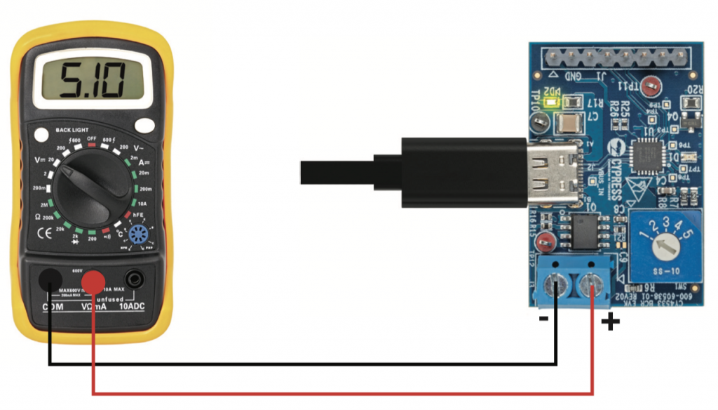
To get this going I start with the Cypress CY4533 development kit which you can see in the picture below.

This board has

  1. A place to plug in Type-C
  2. A 5 position switch to tell the EZ-PD chip to select (5, 9,12,15 or 20V)
  3. Screw terminals for the output voltage
  4. A header with an I2C connection to the EZ-PD chip
  5. A load switch to isolate the load

Here is a block diagram

The kit quick start guide has a picture of exactly what I did next

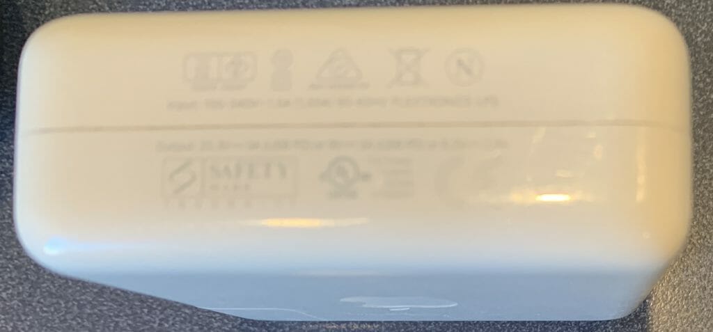
When I turned the selector, I noticed that the output from my Apple charger was (5, 9, 9, 9, 20) and wondered why.  Yet, when I measured another Type-C power supply I got (5, 9, 12, 15, and 20).  It turns out that when you read the fine print on the side of the charger it tells you the answer.  Here is a picture of the side where unfortunately you can’t read (but I used a magnifying glass)

  • 20V @ 3A = 60W
  • 9V @ 3A = 27W
  • 5V @ 2.4A = 12W

The kit guide gives you the answer as to why 5,9,9,9,20:

Infineon

OK.  All that is great, but how do I power my board where I need 5V@12A + 3.6V + 3.3V + 1.8V, this is where Infineon comes into the picture.  Actually, to be completely clear, Infineon came into the picture starting mid-last year when they offered to pay $10B-ish for Cypress.

Infineon makes a line of Buck regulators which are perfect for solving the first part of my problem because

  1. They take high-ish voltage inputs (up to 21V)
  2. They can supply high-ish currents at the right voltage (up to 35A)

These regulators are called the “SupIRBuck” and are part of the “Integrated POL Analog Voltage Regulators (Industrial)

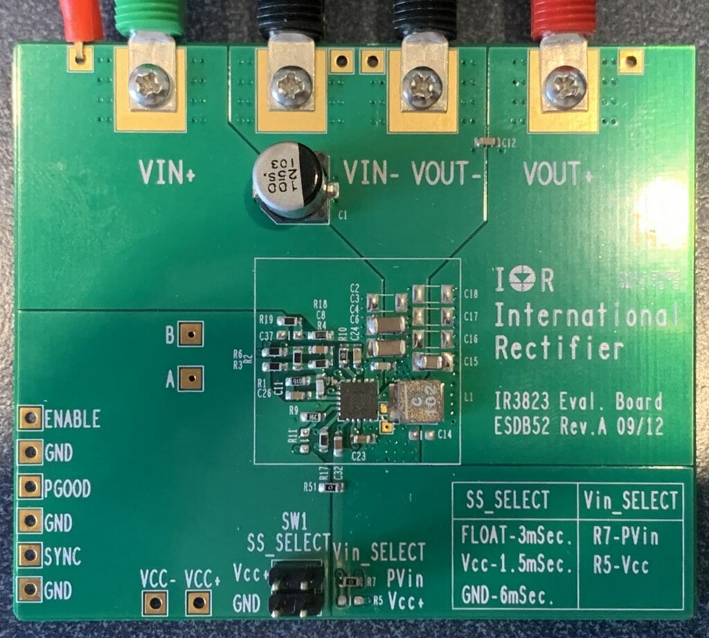
So, I ordered a development kit… unfortunately I  choose the wrong one, IRDC3823 which is 12V @ 3A.  However, it was close enough for me to try out.

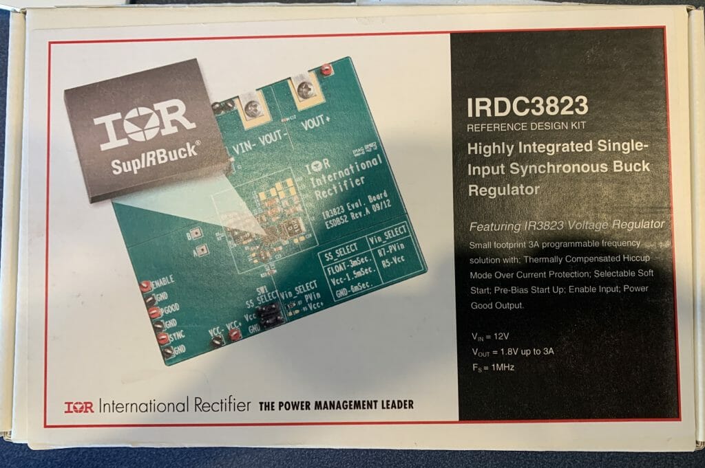
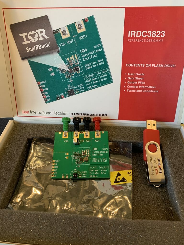
The board came in a box with the kit and a USB stick.

The USB Stick had the Kit Guide, Datasheet, and Gerber Files. That was nice of them.

The kit it actually very simple.  It has a place to plug in your input supply (the two terminals on the left).  And it has a place to plug in the output.

The board also has a place to configure the startup time of the Buck (the little four position jumper).  When I connected the EZ-PD BCR kit to the IR3823 Eval Board, look what I got.  1.2V.  Great.

This is cool and all of that… but I have a bunch of questions that need answering

  1. How do I get 5V out (instead of 1.2V)
  2. Why does the the kit guide say a maximum of 13V on the input?
  3. How do I configure the PGOOD signal to be compatible with the PSoC
  4. How do I measure the efficiency?
  5. What is all this stuff about switching frequency and what is the right number?
  6. What should I choose for SS_Select and why?
  7. What is an “external VCC about?
  8. How do I get 5A (instead of 900mA)?
  9. How do I talk to the EZ-PD chip via I2C?

All of these questions and more are deferred to future articles.


Mouser PSoC 6 WiFi/BT MBED: L1 Developer Resources

IoT Design with Cypress PSoC® 6 MCUs and Wi-Fi/Bluetooth using Arm® Mbed™

# Lesson GitHub Project
0 Introduction
1 Developer Resources
2 Your First Project & The Blinking Thread https://github.com/iotexpert/mouser-mbed-02.git
3 Display Thread https://github.com/iotexpert/mouser-mbed-03.git
4 Temperature Thread https://github.com/iotexpert/mouser-mbed-04.git
5 CapSense Thread https://github.com/iotexpert/mouser-mbed-05.git
6 WiFi & NTP Thread https://github.com/iotexpert/mouser-mbed-06.git
7 The CY8CKIT-062-WiFi-BT https://github.com/iotexpert/mouser-mbed-07.git 
8 Amazon AWS MQTT Thread - Part1 https://github.com/iotexpert/mouser-mbed-08.git
9 Amazon AWS MQTT Thread - Part2 https://github.com/iotexpert/mouser-mbed-09.git

You can “mbed import https://github.com/iotexpert/mouser-mbed-09.git“ to make a copy of the project in your workspace.

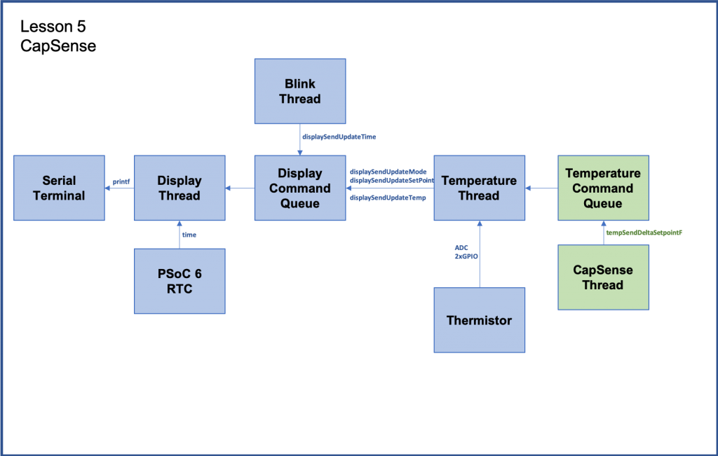
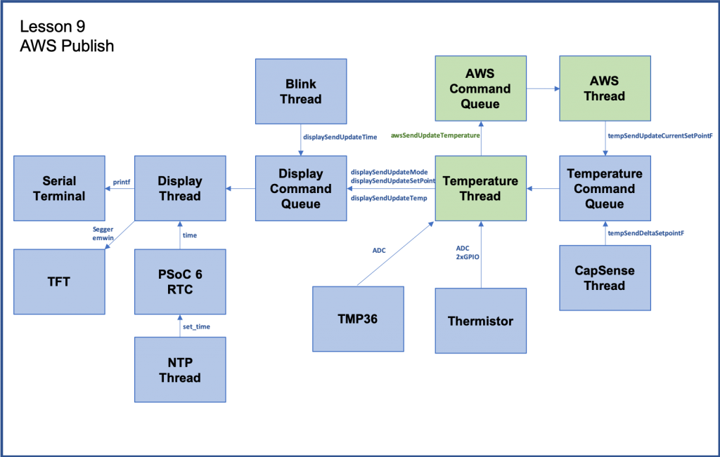
The final architecture of the thermostat looks like this.


Summary

This is an index of links to all of the PSoC 6 MCU, CYW4343W & Mbed OS learning resources.  You can click the links to go the website or see screen captures of the resources.

  1. Mbed OS Overview (screen capture only)
  2. Mbed OS Landing Page
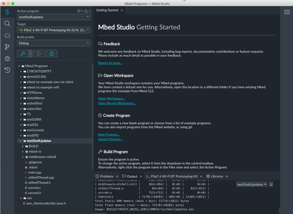
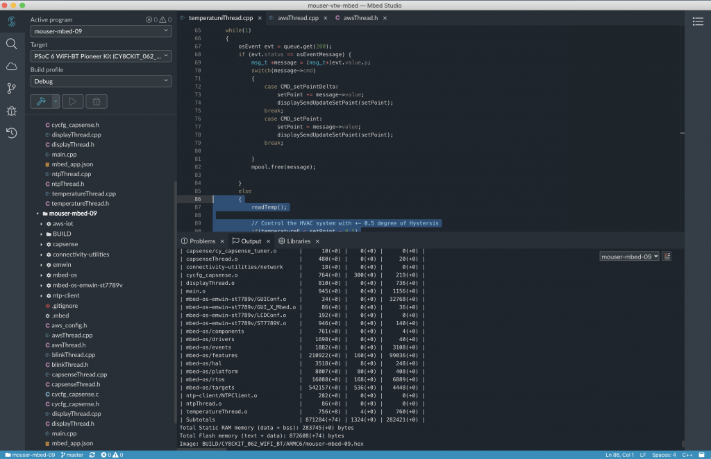
  3. Mbed Studio
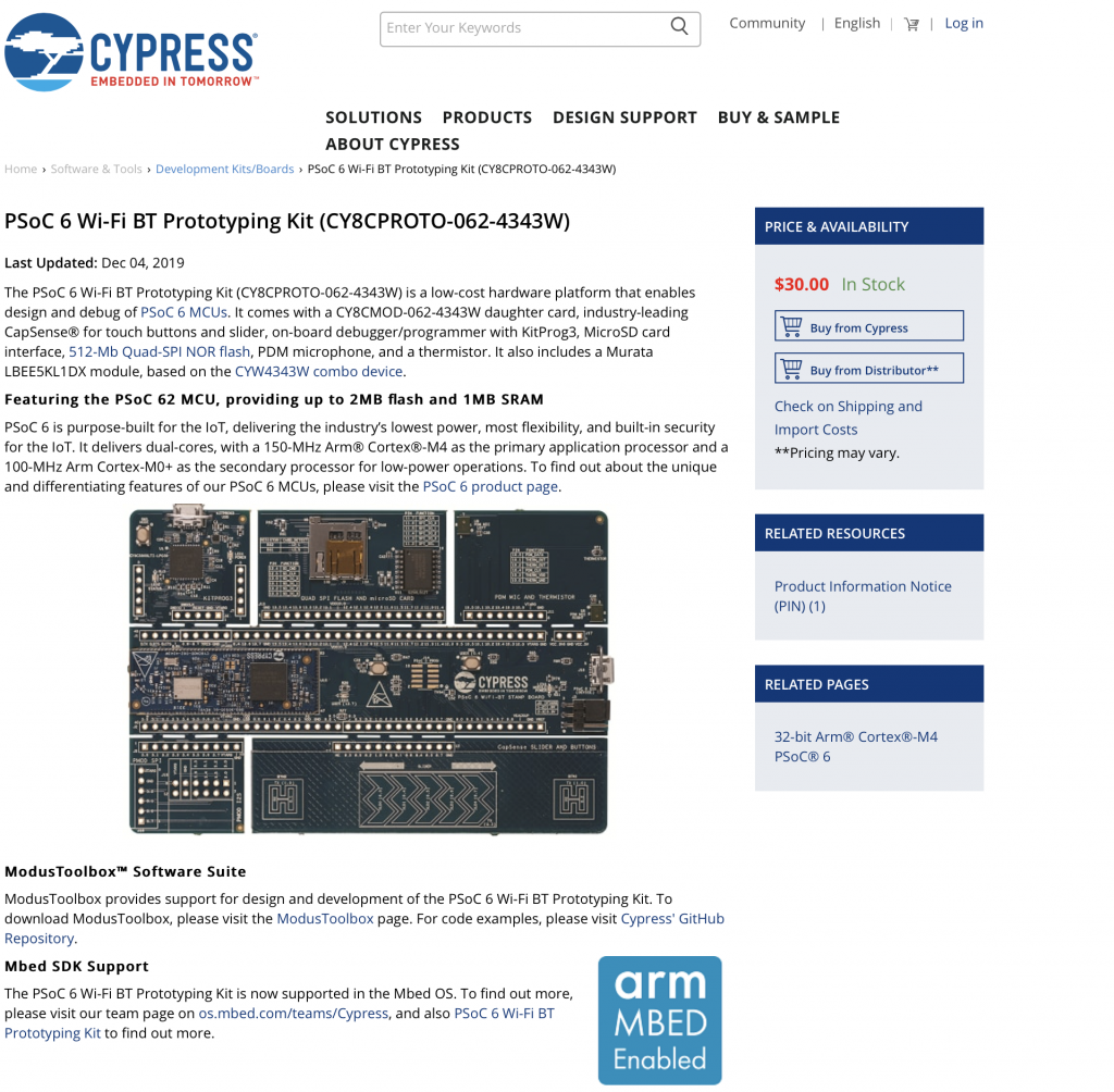
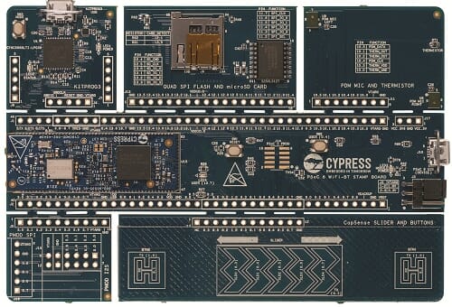
  4. CY8CPROTO-062-4343W
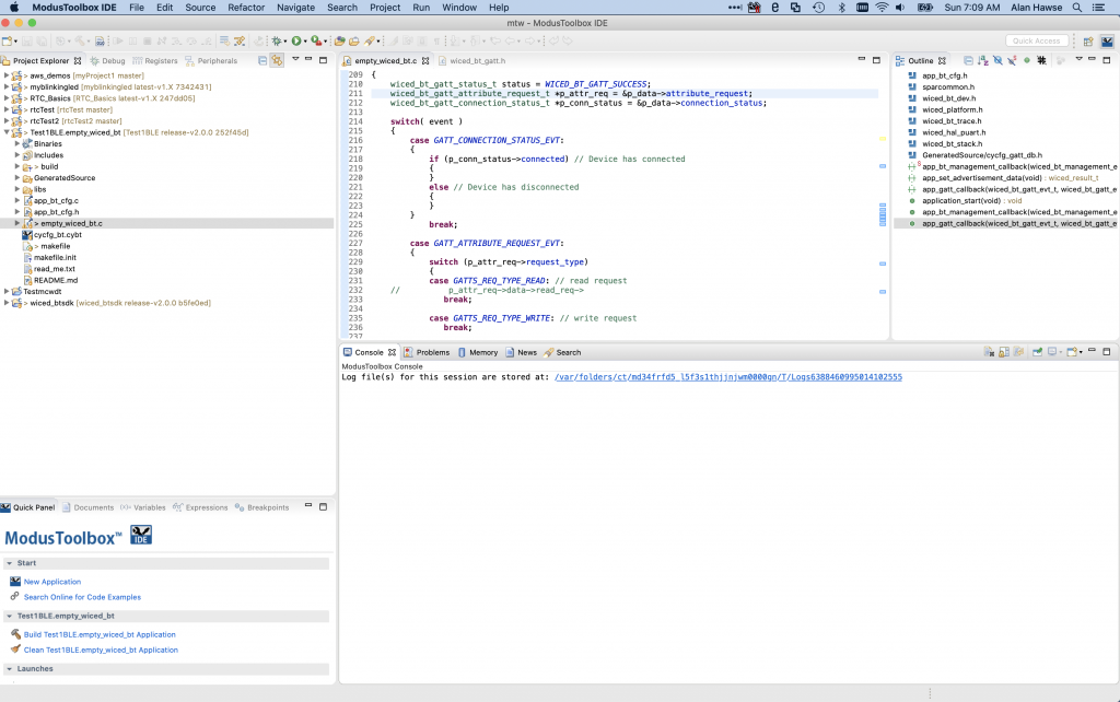
  5. ModusToolbox Software Environment
  6. PSoC 6 Product Page
  7. WiFi + Bluetooth Combo Product Page
  8. PSoC 6 Documentation
  9. PSoC 6 Community
  10. Wireless Combo Community
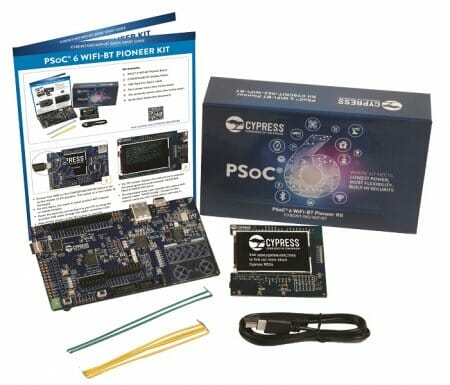
  11. CY8CKIT-062-BT-WiFi Development Kit Product Page
  12. CY8CKIT-062-BT-WiFi Development Kit Guide
  13. PSoC 6 Datasheet
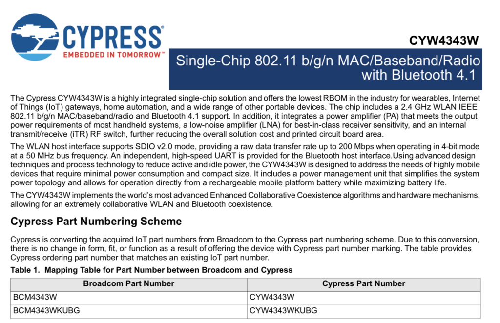
  14. CYW4343W Datasheet
  15. PSoC 6 Technical Reference Manuals
  16. PSoC 6 Application Notes
  17. WiFi + Bluetooth Combo Application Notes
  18. PSoC 6 Code Examples
  19. Video Tutorials
  20. PSoC 6 Knowledge Base
  21. Peripheral Driver Library Documentation (Doxygen – screen capture only)
  22. IoT Expert Website

Mbed OS Overview

Mbed OS Landing Page

The link to the Arm Mbed landing page can be found here.

Mbed Studio

The link to Mbed Studio can be found here.

CY8CPROTO-062-4343W Landing Page

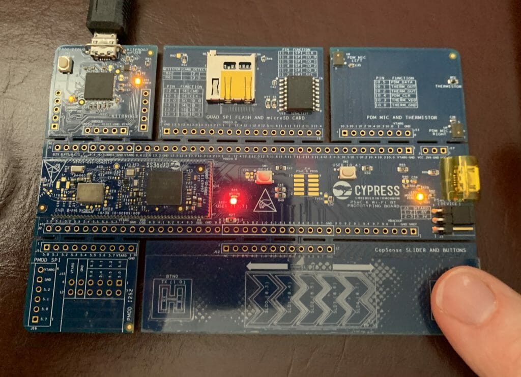
The link to the PSoC 6 WiFi-BT Prototyping Kit (CY8CPROTO-062-4343W) can be found here.

ModusToolbox Software Environment

The link to the ModusToolbox Software Environment landing page can be found here.

PSoC 6 Product Page

You can find the PSoC 6 Product landing page for PSoC 6 here

WiFi + Bluetooth Combo Page

You can find the landing page for all Cypress WiFi + Bluetooth combo radios here.

PSoC 6 Documentation

On the PSoC 6 Product Landing page there is a documentation tab that has links to all of the current documentation.

PSoC 6 Community

Cypress has an active development community and forum.  It can be found here.

Wireless WiFi + Bluetooth Combo Community

The forum on the Cypress Developer Community for WiFi + Bluetooth combo radios can be found here.

CY8CKIT-062-WiFi-BT Development Kit Web Page

Every Cypress development kit has a web page that contains all of the information about it, including links to the documentation and store.  The CY8CKIT-062-WiFi-BT kit page is here.

CY8CKIT-062-WiFi-BT Development Kit Guide

You can find the development kit guide here.

PSoC 6 Datasheet

The PSoC 6 Datasheet is available on Cypress.com here.

CYW4343W Datasheet

The CYW4343W datasheet can be found here.

PSoC 6 Technical Reference Manual

Each of the PSoC 6 devices has a lengthy discussion of the Technical Resources.  These documents can be found here

PSoC 6 Application Notes

You can get them all on our website. Here is a link to the filtered list of PSoC 6 Application Notes.

The best application note is always the “Getting Started”.  In this case it is AN210781 “Getting Started with PSoC 6 MCU with Bluetooth Low Energy (BLE) Connectivity”

WiFi + Bluetooth Combo Application Notes

Here is a link to all of the WiFI Bluetooth Combo Application Notes.

Video Tutorials

Cypress has made a bunch of videos that take you step by step through an introduction to PSoC 6.  You can find them on the Cypress training website.

PSoC 6 Knowledge Base

The Cypress technical support team writes “Knowledge Base” articles when there are repeated issues reported by customers.  You can find them here.

Peripheral Driver Library Documentation (Doxygen)

All of the APIs in the PDL are documented in a Doxygen generated HTML document.  You can get there from

  • Help -> Peripheral Driver Library (this link is live only when you have a PSoC 6 project open)
  • Right click on a component -> Open PDL Documentation

Mouser PSoC 6 WiFi/BT MBED: L2 The Blinking Thread

IoT Design with Cypress PSoC® 6 MCUs and Wi-Fi/Bluetooth using Arm® Mbed™

# Lesson GitHub Project
0 Introduction
1 Developer Resources
2 Your First Project & The Blinking Thread https://github.com/iotexpert/mouser-mbed-02.git
3 Display Thread https://github.com/iotexpert/mouser-mbed-03.git
4 Temperature Thread https://github.com/iotexpert/mouser-mbed-04.git
5 CapSense Thread https://github.com/iotexpert/mouser-mbed-05.git
6 WiFi & NTP Thread https://github.com/iotexpert/mouser-mbed-06.git
7 The CY8CKIT-062-WiFi-BT https://github.com/iotexpert/mouser-mbed-07.git 
8 Amazon AWS MQTT Thread - Part1 https://github.com/iotexpert/mouser-mbed-08.git
9 Amazon AWS MQTT Thread - Part2 https://github.com/iotexpert/mouser-mbed-09.git

You can “mbed import https://github.com/iotexpert/mouser-mbed-09.git“ to make a copy of the project in your workspace.

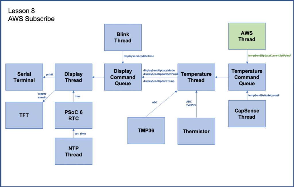
The final architecture of the thermostat looks like this.


Summary

Here we are again. The blinking LED.  I always start with a basic Blinking LED project just to make sure that everything is working.  What is everything?  The whole tool flow, from the editor, to the programmer, to the chip to the SDK.  The only thing that will be a little different than usual is that I will run the blinking LED in a thread by itself. This is useful for looking at the development kit and knowing that the RTOS is still running and the blinking LED thread is at least OK even if the rest of your program is trashed.

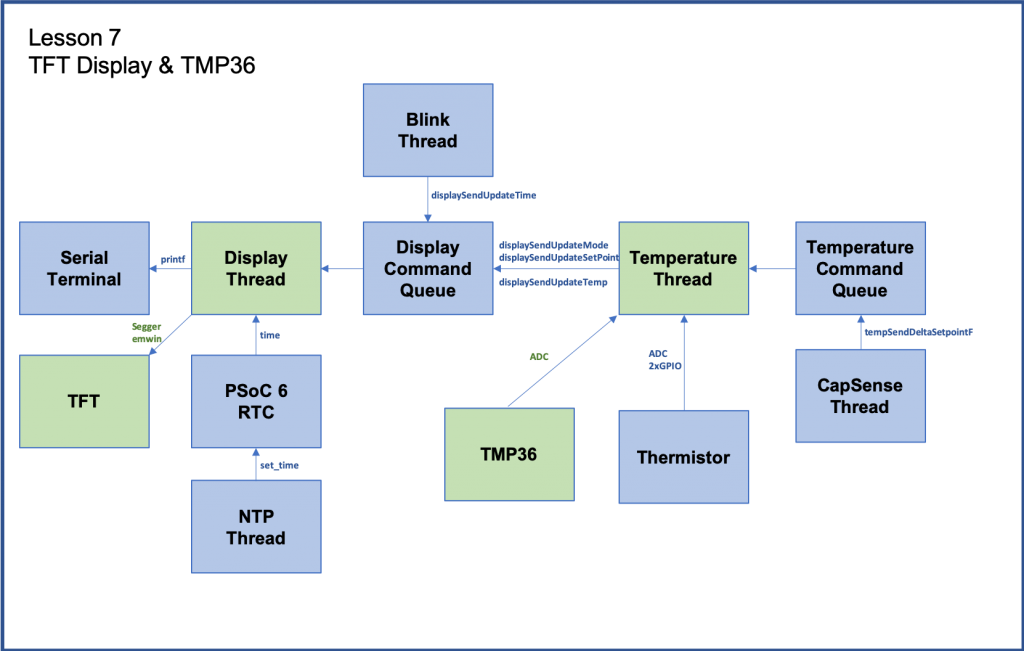
In each of the following lessons I will add on a new block (or two) into the architecture.  The blocks colored “green” will be the ones that are done in that lesson.  In future lessons the blocks that are blue will be from the previous lessons.

For all of these projects I will be using the Mbed Studio program to create, edit, build and program the development board.

To implement the blinking LED thread I will:

  1. Make a new Mbed OS Program from the blank template
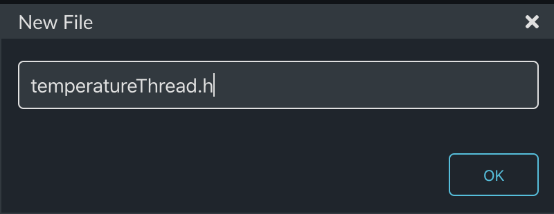
  2. Create & code “blinkThread.h”
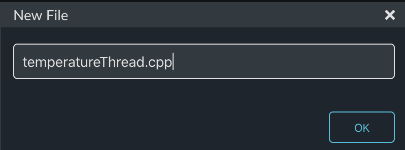
  3. Create & code “blinkThread.cpp”
  4. Update main.cpp
  5. Give a Tour of Targets
  6. Compile and Program

Make a new Mbed OS Program from the blank template

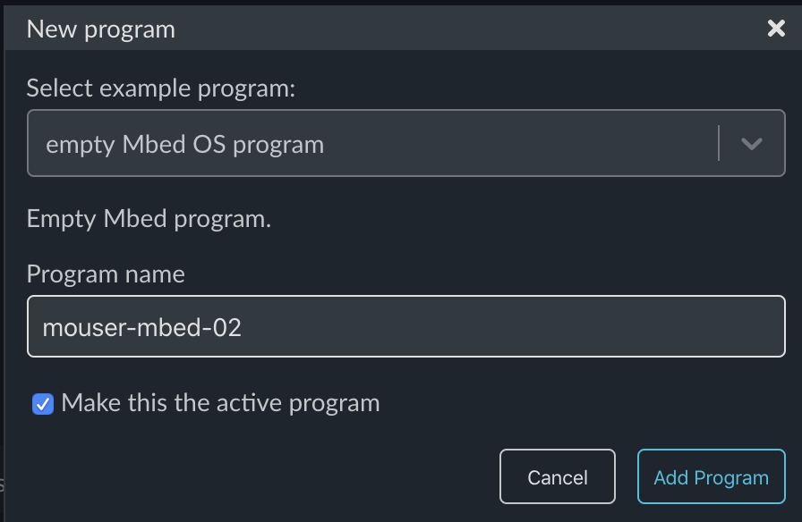
Start Mbed Studio.  Then run “File->New Program…”

Mbed Studio will then give you the ability to start with a template project.  To get started use “empty Mbed OS program”.  For each of the projects I will give it a name that corresponds to the lesson number, in this case “mouser-mbed-02”.  When you have all that selected click “Add Program”.

This will create a brand new project for you with Mbed OS setup and a blank main.cpp.

Create & code “blinkThread.h”

In each of the following lessons I will be creating different threads to perform the different pieces of system functionality.  I will put each thread in a separate set of files with the name “functionThread.h” and “functionThread.cpp”.  As I am sure everyone knows, the “dot h” file is supposed to be the public interface to the “dot cpp” file.  In other words that file has all of the functions, objects and variables that other files are allowed to access.

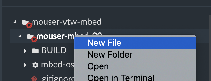
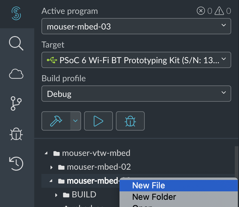
To create a file you “right click” on the project and select “New File”

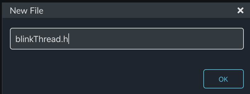
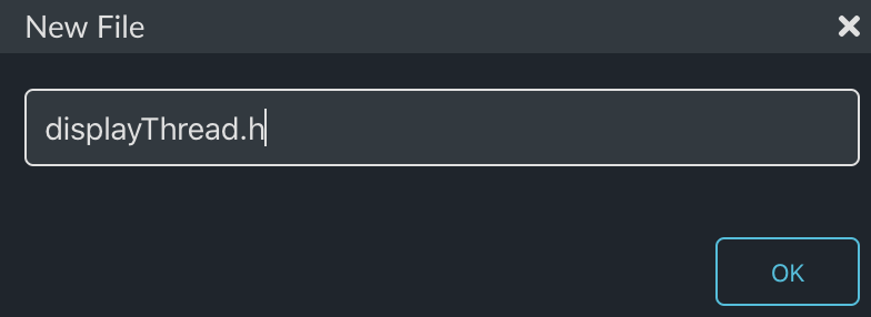
And then give the file a name.  In this case it will be “blinkThread.h”.

This file will have the guards, to keep it from being included more than once, and just the function prototype for the thread.  In all of the coming lessons I will name the thread “functionThread”.  In this case the function is “blink” so the thread is called “blinkThread”

#ifndef BLINK_THREAD_H
#define BLINK_THREAD_H

void blinkThread();

#endif

Create & code “blinkThread.cpp”

Now I am ready to write the actual function which acts as the blinking LED thread.  Right click on the project and select “New File”

Then give it the name “blinkThread.cpp”.  Just like the “dot h” files, the “dot cpp” files will be named “functionThread.cpp”.  In this case the function is blink so the file will be called “blinkThread.cpp”.

This is a really simple thread.  It wants to talk to the LED on the board.  All Mbed OS development boards are required to have at least one LED and that LED must be named “LED1”.  In reality the LED1 is just a map to the PSoC pin name of “P1_1” (this happens in the BSP/Target – more on this later).

By creating an object of type “DigitalOut” with an initializer argument of “LED1” I will have access to writing 1’s and 0’s to that pin.  Notice that I give the object definition the keyword “static” to limits its scope to this file.

The next thing that I need is the actual function which serves as the thread.  Notice that it is an infinite loop, which just does the following:

1. Inverts led1 by reading the pin, inverting it with the “!”, and then writing it back to the pin.

2. Doing a delay of 500 ms using the Mbed OS library function “sleep_for”.  For those of you who aren’t CPP people the “ThisThread::” just tells the compiler that the sleep_for function is in the namespace “ThisThread”.

#include "mbed.h"
#include "blinkThread.h"


static DigitalOut led1(LED1);

void blinkThread()
{
 
    while (true) 
    {
        led1 = !led1;
        ThisThread::sleep_for(500);
    }
}

Update main.cpp

In each of the following lessons, each time I create a new file, I will be making the same basic change to main.cpp.  Specifically I will startup the thread when the main function starts.  To do this:

  1. Include the new “functionThread.h” (in this case “blinkThread.h”).
  2. Declare an object to hold the new thread (in this case “blinkThreadHandle”).
  3. Start the thread by calling the start method with a function pointer to the actual thread function (in this case “blinkThread”).
#include "mbed.h"
#include "blinkThread.h"

Thread blinkThreadHandle;

int main()
{

    printf("Started System\n");

    blinkThreadHandle.start(blinkThread);
}

Targets Tour

Mbed OS abstracts all information about a development board into a set of files called the Target. These files reside in the mbed-os/targets directory.  This files are classically called the board support package (BSP).  This including information about which chip, startup code, libraries, and peripherals exist on the board.

In order to build a project you need to tell Mbed OS which target you are using.  This can be done in the Mbed CLI with  “mbed config target CY8CPROTO_062_4343W” or by selecting the correct target in the Mbed Studio IDE.

You should look in the following directories/files:

  1. mbed-os
  2. targets directory
  3. targets.json
  4. TARGET_Cypress directory
  5. One directory per Target

Compile and Program

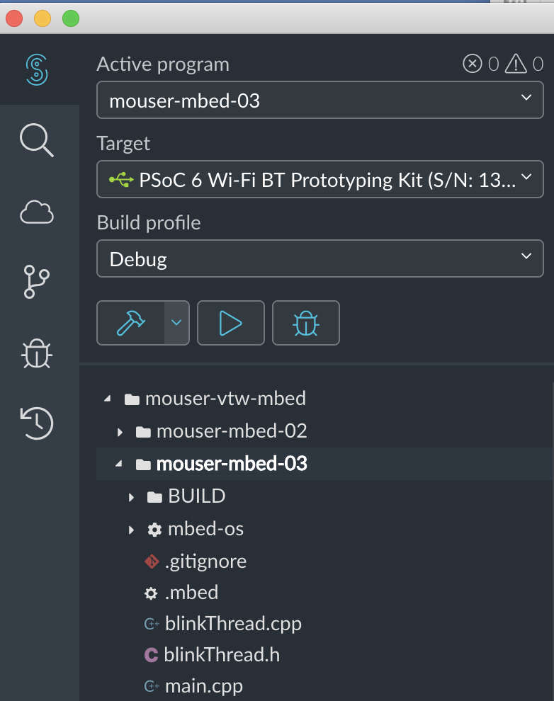
There are several things that you should notice on the panel to the left of your code.

  1. The active program (this is a drop down menu with each project in your workspace).
  2. Which “target”.  When you plug in the development kit, Mbed Studio will recognize that you have attached a target that it recognizes.
  3. The “hammer” button runs the Build process.
  4. The “play” button runs a “Build” then programs the development kit.

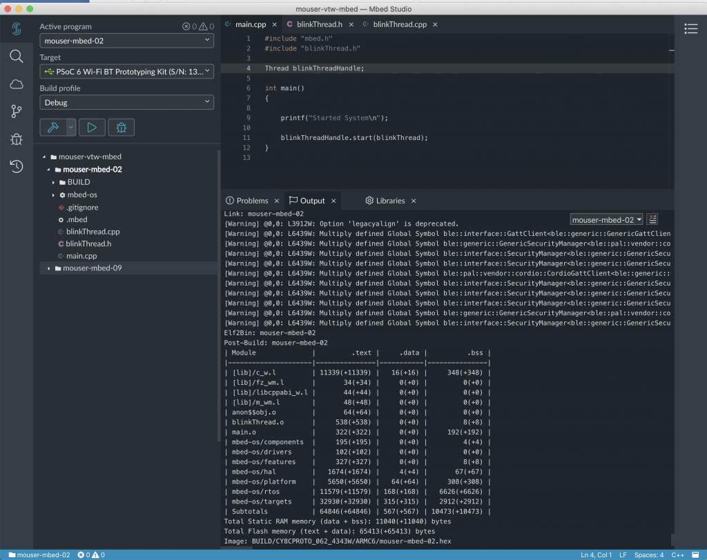
Press the “Play” button to Compile and Program.  And with any luck you should have a blinking LED.

Notice that it compiles a bunch of different files… actually all of the files in mbed-os.  This will take a while on a PC, but is much faster on a Mac or Linux.  This full compile step only needs to happen the first time for a project – each subsequent time will only compile your changes.

Mouser PSoC 6 WiFi/BT MBED: L3 Display Thread

IoT Design with Cypress PSoC® 6 MCUs and Wi-Fi/Bluetooth using Arm® Mbed™

# Lesson GitHub Project
0 Introduction
1 Developer Resources
2 Your First Project & The Blinking Thread https://github.com/iotexpert/mouser-mbed-02.git
3 Display Thread https://github.com/iotexpert/mouser-mbed-03.git
4 Temperature Thread https://github.com/iotexpert/mouser-mbed-04.git
5 CapSense Thread https://github.com/iotexpert/mouser-mbed-05.git
6 WiFi & NTP Thread https://github.com/iotexpert/mouser-mbed-06.git
7 The CY8CKIT-062-WiFi-BT https://github.com/iotexpert/mouser-mbed-07.git 
8 Amazon AWS MQTT Thread - Part1 https://github.com/iotexpert/mouser-mbed-08.git
9 Amazon AWS MQTT Thread - Part2 https://github.com/iotexpert/mouser-mbed-09.git

You can “mbed import https://github.com/iotexpert/mouser-mbed-09.git“ to make a copy of the project in your workspace.

The final architecture of the thermostat looks like this.


Summary

In this lesson we will add an output capability to our project.  But what output device?  I am going old school with a serial terminal using VT100 graphics commands.

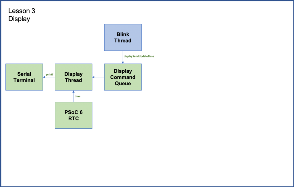
Here is the update to the architecture.  Notice the new green boxes.

  1. A new thread (called Display Thread)
  2. The Serial terminal
  3. An RTC (the one built into the PSoC 6)
  4. An RTOS Queue called “Display Command Queue”
  5. A function called displaySendUpdateTime (to tell the display to show the time)

The way this will work is a new thread called “displayThread” will be created.  I will have an RTOS queue associated with it.  Tasks that want to display something will push a message into the queue.  The display thread will wait around until some other task pushes a message into the queue.  When another task pushes a message, the displayThread will process the message and “do the needful”.

To implement this I will:

  1. Import from GitHub lesson02
  2. Discuss VT100 Commands
  3. Create & code displayThread.h
  4. Create & code displayThread.cpp
  5. Create & code mbed_app.json
  6. Update blinkThread.cpp
  7. Update main.cpp
  8. Build, Program and Test

Import from GitHub Lesson 02

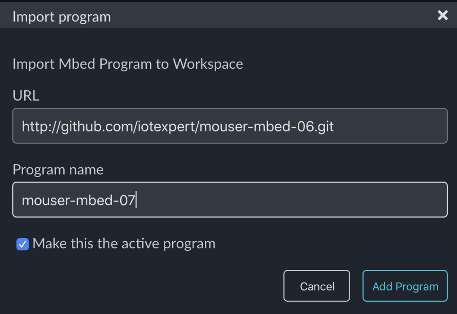
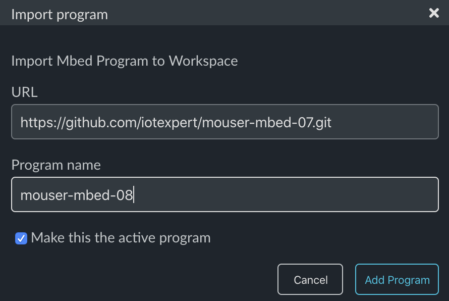
Mbed Studio can start a new project by “importing” an old project and giving it a new name.  This is a super convenient way for me to build each project for this class on the base of the previous one.  To make this easier for you I save each of these lesson projects on GitHub so you can start from there.

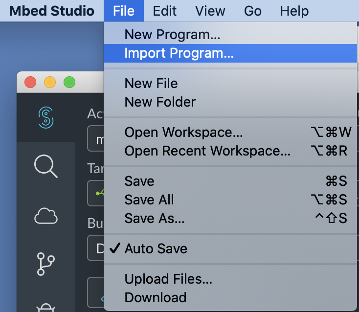
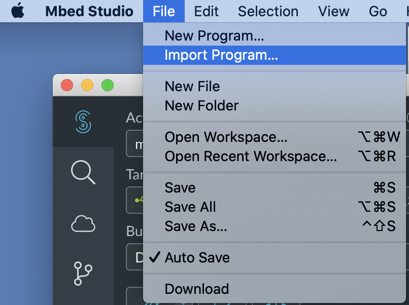
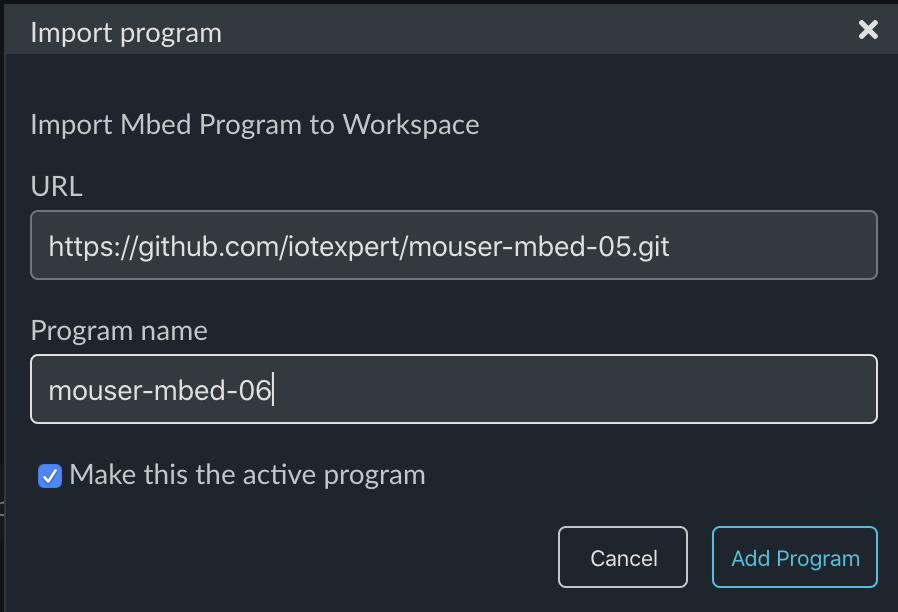
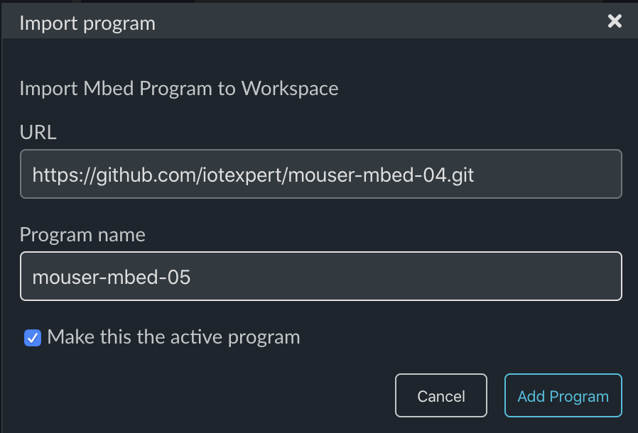
In Mbed Studio use “File->Import Program…”

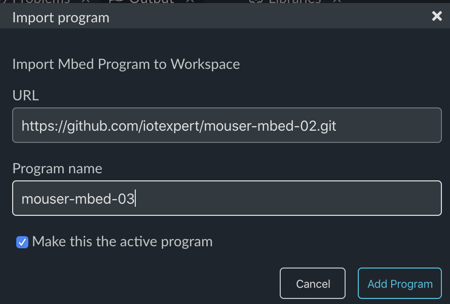
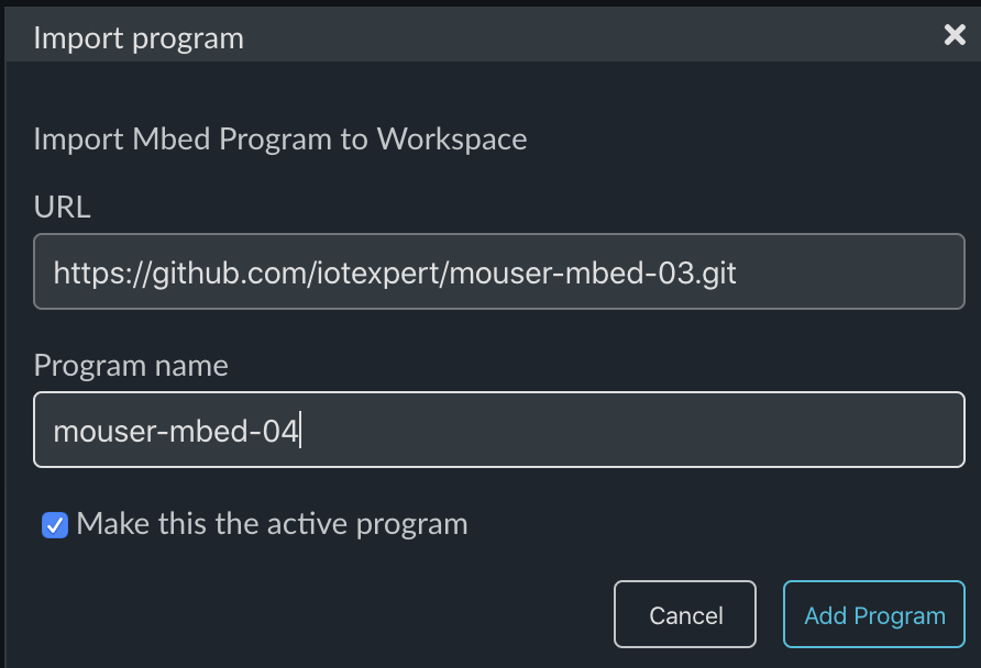
Give it the path to my github site for the project you want to start from:

https://github.com/iotexpert/mouser-mbed-02.git

And then give it the new name you want for the new project – in this case mouser-mbed-03

After clicking “Add program” you should have a new program called “mouser-mbed-03” and it should be set as the active program.

At this point you could press the play button and get exactly the same behavior as the previous lesson 02.

VT100 Commands

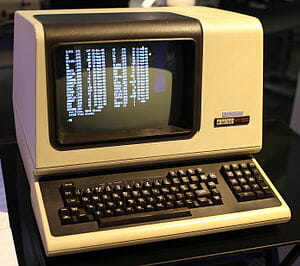
Back in the dark ages when I started programming, most work was done on a “main frame” of some kind or the other.  The two that I used were the PDP-11 and the Prime.  To access these systems you typically used a “Dumb Terminal” attached to the mainframe via a long serial cable.  One of the most used terminals was the VT100 made by Digital Equipment Corporation (DEC).

These terminals could output a fixed width font in about 80 columns and 24 rows.  Basically, the mainframe sent ASCII characters and the terminal would display them.

An interesting feature that was put into these terminals was the ability to take commands and move the cursor around to screen, or clear it, or draw a line or ….

What does that have to do with today?  Simple, the VT100 command set is still used by almost all serial programs on your PC (Putty, etc).  And I am going to use these commands to create a graphical user interface for the thermostat that looks like this:

  • Line 1 will be the current temperature
  • Line 2 will be the setPoint of the thermostat
  • Line 3 will be the time
  • Line 4 will be the status of the system (Heat, Cool or Off)

To use the VT100 commands you just use printf to send them to the serial terminal.  The commands I will use are:

Command ESC Sequence printf
Home ESC [ H printf("\033[H");
Clear Screen ESC [ J printf("\033[2J");
Turn Cursor Off ESC [ ? 25l printf("\033[?25l");
Goto column & row ESC [ column ; row H printf("\033[%d;%dH%s",y,x,buffer);

Add displayThread.h

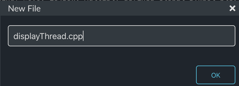
As in lesson 02 I will create a new thread.  This time the header file will be called “displayThread.h”  Right click and select “New File”

Give it the name “displayThread.h”

This file will:

  1. Guard against multiple include
  2. Provide the function prototype of the thread
  3. Provide four functions to tell the displayThread to write onto the four different lines of the GUI
#ifndef DISPLAY_THREAD_H
#define DISPLAY_THREAD_H

void displayThread();


void displaySendUpdateTemp(float temperature);
void displaySendUpdateTime();
void displaySendUpdateSetPoint(float setPoint);
void displaySendUpdateMode(float mode);

#endif

Add displayThread.cpp

From now on I will just show the file creation.  In this case “displayThread.cpp”

The first part of the file is to specify the queue.  To do this I create a new type called msg_t which will be inserted into the queue (actually a pointer to the msg_t).  The message structure will have two members the “command_t” and a generic floating point variable called “value”.

The Queue and Memory pool will only be accessible inside of this file.  The queue will hold up to 16 “msg_t”.  The MemoryPool is just an easy  way to do memory allocation.

#include "mbed.h"
#include "displayThread.h"

typedef enum {
    CMD_temperature,
    CMD_setPoint,
    CMD_time,
    CMD_mode,
} command_t;


typedef struct {
    command_t cmd;
    float    value;
} msg_t;


static Queue<msg_t, 16> queue;
static MemoryPool<msg_t, 16> mpool;

In order to insert msg_t into the queue I create one function per msg_t that:

  • allocates a new message
  • sets the command
  • sets the value
  • puts the message in the queue

Notice if something goes wrong, I just ignore the problem.  In a real system you would probably want to do something else.

These four functions will actually run inside of the thread that calls them, but they will insert messages into the queue that the displayThread is processing.  This queue mechanism is a safe way for processes to talk to each other.

// Function called by other threads to queue a temperature change onto the display
void displaySendUpdateTemp(float temperature)
{
    msg_t *message = mpool.alloc();
    if(message)
    {
        message->cmd = CMD_temperature;
        message->value = temperature;
        queue.put(message);
    }
}

// Function called by other threads to queue display to update time
void displaySendUpdateTime()
{
    msg_t *message = mpool.alloc();
    if(message)
    {
        message->cmd = CMD_time;
        message->value = 0;
        queue.put(message);
    }
}

// Function called by other threads to queue a setPoint change onto the display
void displaySendUpdateSetPoint(float setPoint)
{
    msg_t *message = mpool.alloc();
    if(message)
    {
        message->cmd = CMD_setPoint;
        message->value = setPoint;
        queue.put(message);
    }
}

// Function called by other threads to queue a setPoint change onto the display
void displaySendUpdateMode(float mode)
{
    msg_t *message = mpool.alloc();
    if(message)
    {
        message->cmd = CMD_mode;
        message->value = mode;
        queue.put(message);
    }
}

The function displayAtXY creates a string with the VT100 Goto command plus the string that was send.

static void displayAtXY(int x, int y,char *buffer)
{
    // row column
    printf("3[%d;%dH%s",y,x,buffer);
    fflush(stdout);
}

The actual display thread:

  • Clears the screen and turns the cursor off
  • Goes into an infinite loop waiting for messages to be put into the queue
  • When a new message comes in, look at the command
  • sprintf to create the display message
  • print it using the displayAtXY function
void displayThread()
{
    char buffer[128];

    printf("3[2J3[H"); // Clear Screen and go Home
    printf("3[?25l"); // Turn the cursor off
    fflush(stdout);

    while(1)
    {
        osEvent evt = queue.get();
        if (evt.status == osEventMessage) {
            msg_t *message = (msg_t*)evt.value.p;
            switch(message->cmd)
            {
                case CMD_temperature:
                    sprintf(buffer,"Temperature = %2.1fF",message->value);
                    displayAtXY(1, 1, buffer);
                break;
                case CMD_setPoint:
                    sprintf(buffer,"Set Point = %2.1fF",message->value);
                    displayAtXY(1, 2, buffer);
                break;
                case CMD_time:
                    time_t rawtime;
                    struct tm * timeinfo;
                    time (&rawtime);
                    rawtime = rawtime - (5*60*60); // UTC - 4hours ... serious hack which only works in winter
                    timeinfo = localtime (&rawtime);
                    strftime (buffer,sizeof(buffer),"%r",timeinfo);
                    displayAtXY(1,3, buffer);
                break;
                case CMD_mode:
                    if(message->value == 0.0)
                        sprintf(buffer,"Mode = Off ");
                    else if (message->value < 0.0)
                        sprintf(buffer,"Mode = Heat");
                    else
                        sprintf(buffer,"Mode = Cool");
                    displayAtXY(1, 4, buffer);
                break;

            }
            mpool.free(message);

        }
    }
}

Here is the whole file displayThread.cpp (to make a copy/paste easier):

#include "mbed.h"
#include "displayThread.h"

typedef enum {
    CMD_temperature,
    CMD_setPoint,
    CMD_time,
    CMD_mode,
} command_t;


typedef struct {
    command_t cmd;
    float    value;
} msg_t;


static Queue<msg_t, 32> queue;
static MemoryPool<msg_t, 16> mpool;

// Function called by other threads to queue a temperature change onto the display
void displaySendUpdateTemp(float temperature)
{
    msg_t *message = mpool.alloc();
    if(message)
    {
        message->cmd = CMD_temperature;
        message->value = temperature;
        queue.put(message);
    }
}

// Function called by other threads to queue display to update time
void displaySendUpdateTime()
{
    msg_t *message = mpool.alloc();
    if(message)
    {
        message->cmd = CMD_time;
        message->value = 0;
        queue.put(message);
    }
}

// Function called by other threads to queue a setPoint change onto the display
void displaySendUpdateSetPoint(float setPoint)
{
    msg_t *message = mpool.alloc();
    if(message)
    {
        message->cmd = CMD_setPoint;
        message->value = setPoint;
        queue.put(message);
    }
}

// Function called by other threads to queue a setPoint change onto the display
void displaySendUpdateMode(float mode)
{
    msg_t *message = mpool.alloc();
    if(message)
    {
        message->cmd = CMD_mode;
        message->value = mode;
        queue.put(message);
    }
}

static void displayAtXY(int x, int y,char *buffer)
{
    // row column
    printf("3[%d;%dH%s",y,x,buffer);
    fflush(stdout);
}


///////////////////////////////////////////////////////////////////////////////////////////////////////////

void displayThread()
{
    char buffer[128];

    printf("3[2J3[H"); // Clear Screen and go Home
    printf("3[?25l"); // Turn the cursor off
    fflush(stdout);

    while(1)
    {
        osEvent evt = queue.get();
        if (evt.status == osEventMessage) {
            msg_t *message = (msg_t*)evt.value.p;
            switch(message->cmd)
            {
                case CMD_temperature:
                    sprintf(buffer,"Temperature = %2.1fF",message->value);
                    displayAtXY(1, 1, buffer);
                break;
                case CMD_setPoint:
                    sprintf(buffer,"Set Point = %2.1fF",message->value);
                    displayAtXY(1, 2, buffer);
                break;
                case CMD_time:
                    time_t rawtime;
                    struct tm * timeinfo;
                    time (&rawtime);
                    rawtime = rawtime - (5*60*60); // UTC - 4hours ... serious hack which only works in winter
                    timeinfo = localtime (&rawtime);
                    strftime (buffer,sizeof(buffer),"%r",timeinfo);
                    displayAtXY(1,3, buffer);
                break;
                case CMD_mode:
                    if(message->value == 0.0)
                        sprintf(buffer,"Mode = Off ");
                    else if (message->value < 0.0)
                        sprintf(buffer,"Mode = Heat");
                    else
                        sprintf(buffer,"Mode = Cool");
                    displayAtXY(1, 4, buffer);
                break;

            }
            mpool.free(message);

        }
    }
}

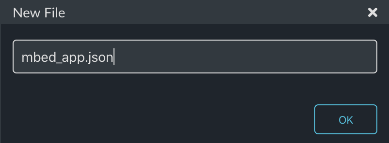
Create mbed_app.json

By default the serial terminal on Mbed OS is 9600 baud or approximately the same speed as back in VT100 days.  Fortunately you can change that by setting up a global configuration.  To do this you need to create a file called “mbed_app.json”.

In that file, I tell the system that I want 115200 baud for all targets.

{
    "target_overrides": {
        "*": {
            "platform.stdio-baud-rate": 115200
        }
    }
}

Update blinkThread.cpp

In order to test the new displayThread, I will fix up the blinkThread to temporarily send the four messages.

#include "mbed.h"
#include "blinkThread.h"
#include "displayThread.h"

static DigitalOut led1(LED1);

void blinkThread()
{
 
    while (true) 
    {
        led1 = !led1;
        displaySendUpdateTime();
        displaySendUpdateTemp(69.2);
        displaySendUpdateSetPoint(23.5);
        displaySendUpdateMode(-1.0);
        ThisThread::sleep_for(500);
    }
}

Update main.cpp

The last step is to update main to start the new displayThread.

#include "mbed.h"
#include "blinkThread.h"
#include "displayThread.h"

Thread blinkThreadHandle;
Thread displayThreadHandle;

int main()
{

    printf("Started System\n");

    blinkThreadHandle.start(blinkThread);
    displayThreadHandle.start(displayThread);

}

Build, Program and Test

Now press the play button.

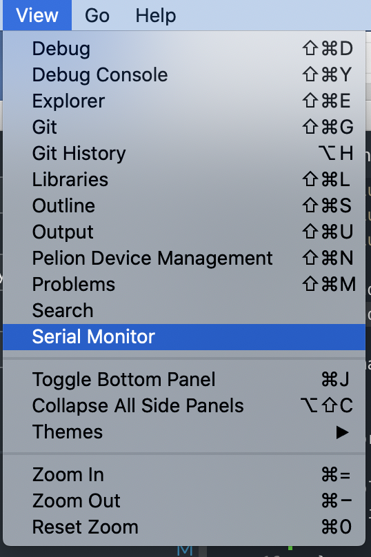
One nice thing in Mbed Studio is a built-in serial port viewer.  You can use it by clicking “View -> Serial Monitor”

Change the baud rate to 115200 and you should see something like this:

Mouser PSoC 6 WiFi/BT MBED: L4 Temperature Thread

IoT Design with Cypress PSoC® 6 MCUs and Wi-Fi/Bluetooth using Arm® Mbed™

# Lesson GitHub Project
0 Introduction
1 Developer Resources
2 Your First Project & The Blinking Thread https://github.com/iotexpert/mouser-mbed-02.git
3 Display Thread https://github.com/iotexpert/mouser-mbed-03.git
4 Temperature Thread https://github.com/iotexpert/mouser-mbed-04.git
5 CapSense Thread https://github.com/iotexpert/mouser-mbed-05.git
6 WiFi & NTP Thread https://github.com/iotexpert/mouser-mbed-06.git
7 The CY8CKIT-062-WiFi-BT https://github.com/iotexpert/mouser-mbed-07.git 
8 Amazon AWS MQTT Thread - Part1 https://github.com/iotexpert/mouser-mbed-08.git
9 Amazon AWS MQTT Thread - Part2 https://github.com/iotexpert/mouser-mbed-09.git

You can “mbed import https://github.com/iotexpert/mouser-mbed-09.git“ to make a copy of the project in your workspace.

The final architecture of the thermostat looks like this.


Summary

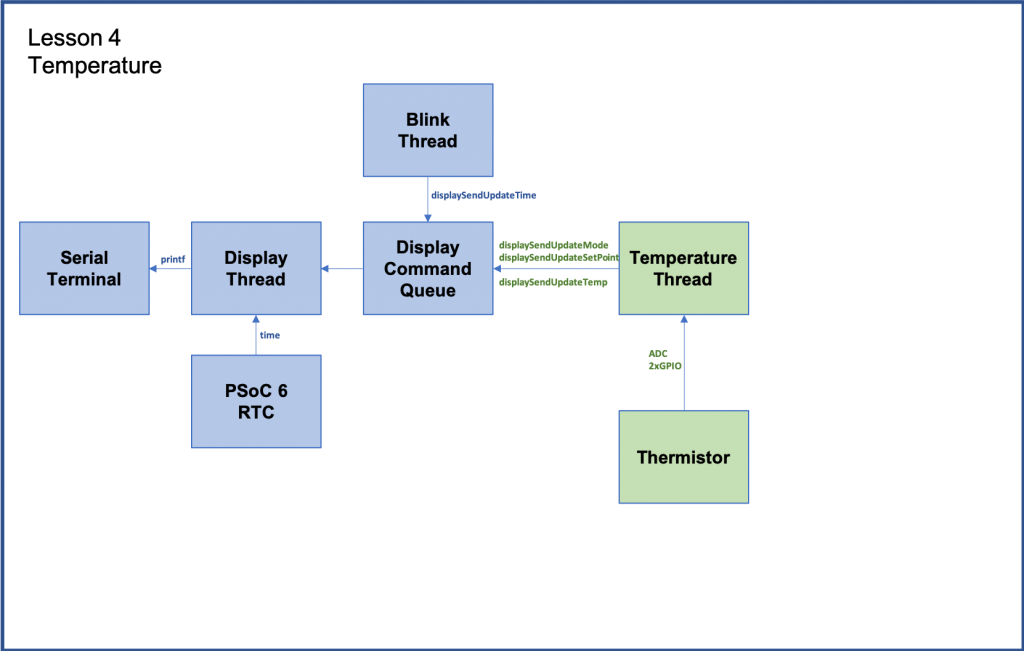
In Lesson 04 I will add temperature sensing to the system.

The new thread called “temperatureThread” acts as the actual guts of the thermostat.  It reads the temperature sensor, keeps track of the setPoint of the system and turns on and off Heat and Cooling.  Notice that it doesn’t know anything about displaying information,  it just uses the functions calls we created for the displayThread.

To implement this I will:

  1. Explain Thermistors
  2. Import lesson03
  3. Create and code temperatureThread.h
  4. Create and code temperatureThread.cpp
  5. Fix blinkThread.cpp
  6. Update main.cpp
  7. Build, Program and Test

Thermistor

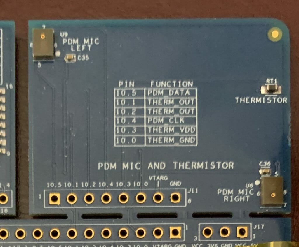
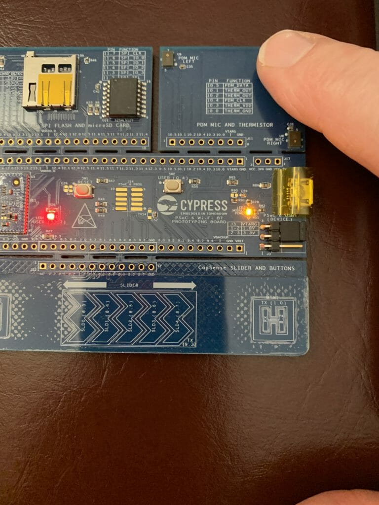
On the wing of the CY8CPROTO-062-4343W there is a thermistor that you can use to measure temperature.   What is a thermistor?  It is simply a resistor that changes resistance in a known way based on temperature.

If you know the resistance you can calculate the temperature using the Steinhart-Hart equation.  Here is the Thermistor Wikipedia article.

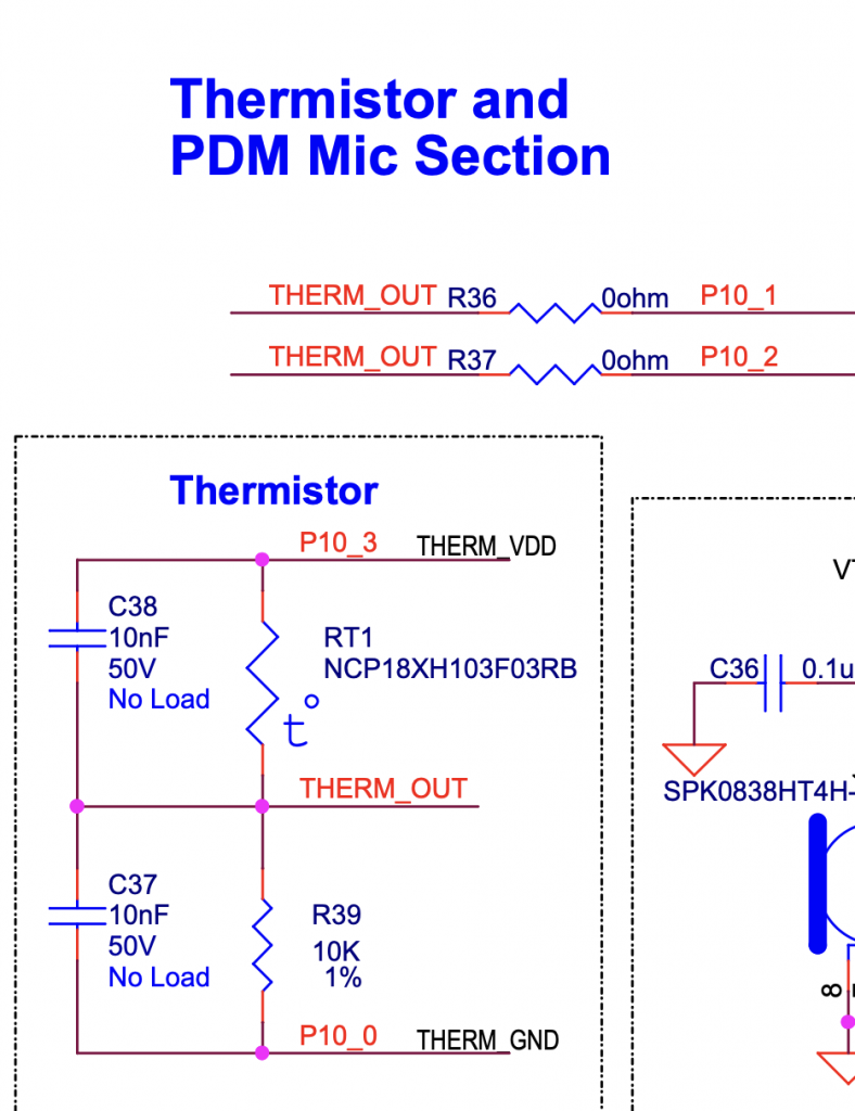
When you look at the schematic for the development kit you can see how the circuit is attached to the PSoC.

Basically, a known 10K resistor in series with the thermistor with a measurement point between them.  To calculate the resistance of the thermistor you use Ohms low, V=IR.  Or even better R=V/I.

To use this circuit you need to assign a voltage to the THERM_VDD, use a DigialOut to drive 3.3v to that signal and a DigialOut to drive ground to the THERM_GND.

Then use the ADC to find the voltage for THERM_OUT

To do the calculation, first the Thermistor voltage is THERM_VDD-THERM_OUT.

Then you need to get the current.  To do this you calculate the current through the reference resistor I=V/R or I=(THERM_OUT/10K).  This will be the same current as the Thermistor.

Now you can calculate the thermistor resistance.

Here is a picture of the thermistor on the board.

Here is the code that implements the thermistor measurement.

static DigitalOut thermVDD(P10_3,1);
static DigitalOut thermGND(P10_0,0);
static AnalogIn thermOut(P10_1);

static void readTemp()
{
    float refVoltage = thermOut.read() * 2.4; // Range of ADC 0->2*Vref
    float refCurrent = refVoltage  / 10000.0; // 10k Reference Resistor
    float thermVoltage = 3.3 - refVoltage;    // Assume supply voltage is 3.3v
    float thermResistance = thermVoltage / refCurrent; 
    float logrT = (float32_t)log((float64_t)thermResistance);

    /* Calculate temperature from the resistance of thermistor using Steinhart-Hart Equation */
    float stEqn = (float32_t)((0.0009032679) + ((0.000248772) * logrT) + 
                             ((2.041094E-07) * pow((float64)logrT, (float32)3)));

    float temperatureC = (float32_t)(((1.0 / stEqn) - 273.15)  + 0.5);
    temperatureF = (temperatureC * 9.0/5.0) + 32;
}

Import Lesson 03

To build the project, start by importing Lesson 03:

https://github.com/iotexpert/mouser-mbed-03.git

Give it a new name of “mouser-mbed-04”:

Create and code temperatureThread.h

As before we want a thread for the temperature system called “temperatureThread.h”.  Create the “dot h”:

This file will just declare the thread and interface functions.

#ifndef TEMPERATURE_H
#define TEMPERATURE_H

void temperatureThread();

void tempSendUpdateSetpointF(float setPoint);
void tempSendDeltaSetpointF(float delta);


#endif

Create and code temperatureThread.cpp

Now we need the actual thread.  Make the new file “temperatureThread.cpp”

This thread will have two state variables.  One for temperatureF and one for the setPoint of the thermostat.

This thread will also have a queue just like the displayThread.  This queue will be used to let other parts of the system change the setPoint. One command to make a “delta” change  e.g. “go up 1 degree” and one command to make an absolute change e.g “set to 78 degrees”

#include "mbed.h"
#include "temperatureThread.h"
#include "displayThread.h"

static float temperatureF;
static float setPoint = 75.0;

static void readTemp();

typedef enum {
    CMD_setPointDelta,
    CMD_setPoint,

} command_t;


typedef struct {
    command_t cmd;
    float    value;   /* AD result of measured voltage */
} msg_t;

As before to make things easier for the other parts of the system to send messages to the queue, I create functions to send the two commands.

void tempSendDeltaSetpointF(float delta)
{
    msg_t *message = mpool.alloc();
    if(message)
    {
        message->cmd = CMD_setPointDelta;
        message->value = delta;
        queue.put(message);
    }
}

void tempSendUpdateSetpointF(float setPoint)
{
    msg_t *message = mpool.alloc();
    if(message)
    {
        message->cmd = CMD_setPoint;
        message->value = setPoint;
        queue.put(message);
    }
}

Now you need the function to read the temperature and update the state variable temperatureF

static DigitalOut thermVDD(P10_3,1);
static DigitalOut thermGND(P10_0,0);
static AnalogIn thermOut(P10_1);

static void readTemp()
{
    float refVoltage = thermOut.read() * 2.4; // Range of ADC 0->2*Vref
    float refCurrent = refVoltage  / 10000.0; // 10k Reference Resistor
    float thermVoltage = 3.3 - refVoltage;    // Assume supply voltage is 3.3v
    float thermResistance = thermVoltage / refCurrent; 
    float logrT = (float32_t)log((float64_t)thermResistance);

    /* Calculate temperature from the resistance of thermistor using Steinhart-Hart Equation */
    float stEqn = (float32_t)((0.0009032679) + ((0.000248772) * logrT) + 
                             ((2.041094E-07) * pow((float64)logrT, (float32)3)));

    float temperatureC = (float32_t)(((1.0 / stEqn) - 273.15)  + 0.5);
    temperatureF = (temperatureC * 9.0/5.0) + 32;
}

The temperatureThread listens for messages to be put into the queue.  It then processes them by either increment/decrement of the setPoint or by setting an absolute setPoint.

Also, the queue wait will timeout every 200ms and when that happens it will read the temperature and update the display.

It will also send the cool, heat or off based on a +- 0.5 degree difference from the setPoint.  In other words:

  • temperatureF > setPoint + 0.5 = cool
  • temperatureF < setPoint -0.5 = heat
  • Otherwise OFF
void temperatureThread()
{

    char buffer[128];
    displaySendUpdateTemp(temperatureF);
    displaySendUpdateSetPoint(setPoint);
    
    while(1)
    {
        osEvent evt = queue.get(200);
        if (evt.status == osEventMessage) {
            msg_t *message = (msg_t*)evt.value.p;
            switch(message->cmd)
            {
                case CMD_setPointDelta:
                    setPoint += message->value;
                    displaySendSetPoint(setPoint);
                break;
                case CMD_setPoint:
                    setPoint = message->value;
                    displaySendUpdateSetPoint(setPoint);
                break;

            }
            mpool.free(message);

        }
        else
        {
            readTemp();

            // Control the HVAC system with +- 0.5 degree of Hystersis
            if(temperatureF < setPoint - 0.5)
                displaySendUpdateMode(-1.0);
            else if (temperatureF > setPoint + 0.5)
                displaySendUpdateMode(1.0);
            else
                displaySendUpdateMode(0.0);

            displaySendUpdateTemp(temperatureF); 
        }
    }

}

The whole file (to make the copy/paste easier):

#include "mbed.h"
#include "temperatureThread.h"
#include "displayThread.h"

static float temperatureF;
static float setPoint = 75.0;

static void readTemp();

typedef enum {
    CMD_setPointDelta,
    CMD_setPoint,

} command_t;


typedef struct {
    command_t cmd;
    float    value;   /* AD result of measured voltage */
} msg_t;


static Queue<msg_t, 32> queue;
static MemoryPool<msg_t, 16> mpool;

void tempSendDeltaSetpointF(float delta)
{
    msg_t *message = mpool.alloc();
    if(message)
    {
        message->cmd = CMD_setPointDelta;
        message->value = delta;
        queue.put(message);
    }
}

void tempSendUpdateSetpointF(float setPoint)
{
    msg_t *message = mpool.alloc();
    if(message)
    {
        message->cmd = CMD_setPoint;
        message->value = setPoint;
        queue.put(message);
    }
}

void temperatureThread()
{

    char buffer[128];
    displaySendUpdateTemp(temperatureF);
    displaySendUpdateSetPoint(setPoint);
    
    while(1)
    {
        osEvent evt = queue.get(200);
        if (evt.status == osEventMessage) {
            msg_t *message = (msg_t*)evt.value.p;
            switch(message->cmd)
            {
                case CMD_setPointDelta:
                    setPoint += message->value;
                    displaySendUpdateSetPoint(setPoint);
                break;
                case CMD_setPoint:
                    setPoint = message->value;
                    displaySendUpdateSetPoint(setPoint);
                break;

            }
            mpool.free(message);

        }
        else
        {
            readTemp();

            // Control the HVAC system with +- 0.5 degree of Hystersis
            if(temperatureF < setPoint - 0.5)
                displaySendUpdateMode(-1.0);
            else if (temperatureF > setPoint + 0.5)
                displaySendUpdateMode(1.0);
            else
                displaySendUpdateMode(0.0);

            displaySendUpdateTemp(temperatureF); 
        }
    }

}


static DigitalOut thermVDD(P10_3,1);
static DigitalOut thermGND(P10_0,0);
static AnalogIn thermOut(P10_1);

static void readTemp()
{
    float refVoltage = thermOut.read() * 2.4; // Range of ADC 0->2*Vref
    float refCurrent = refVoltage  / 10000.0; // 10k Reference Resistor
    float thermVoltage = 3.3 - refVoltage;    // Assume supply voltage is 3.3v
    float thermResistance = thermVoltage / refCurrent; 
    float logrT = (float32_t)log((float64_t)thermResistance);

    /* Calculate temperature from the resistance of thermistor using Steinhart-Hart Equation */
    float stEqn = (float32_t)((0.0009032679) + ((0.000248772) * logrT) + 
                             ((2.041094E-07) * pow((float64)logrT, (float32)3)));

    float temperatureC = (float32_t)(((1.0 / stEqn) - 273.15)  + 0.5);
    temperatureF = (temperatureC * 9.0/5.0) + 32;
}

Fix blinkThread.cpp

Now edit the blinkThread.cpp to remove the test code from Lesson 03:

#include "mbed.h"
#include "blinkThread.h"
#include "displayThread.h"

static DigitalOut led1(LED1);

void blinkThread()
{
 
    while (true) 
    {
        led1 = !led1;
        displaySendUpdateTime();
        ThisThread::sleep_for(500);

    }
}

Update main.cpp

Then update main.cpp to start the new temperatureThread:

#include "mbed.h"
#include "blinkThread.h"
#include "displayThread.h"
#include "temperatureThread.h"

Thread blinkThreadHandle;
Thread displayThreadHandle;
Thread temperatureThreadHandle;

int main()
{

    printf("Started System\n");

    blinkThreadHandle.start(blinkThread);
    displayThreadHandle.start(displayThread);
    temperatureThreadHandle.start(temperatureThread);

}

Build, Program and Test

When you program the development kit you should be able to change the temperature by putting your finger on the thermistor:

And your terminal should look something like this:

Mouser PSoC 6 WiFi/BT MBED: L6 WiFi & NTP Thread

IoT Design with Cypress PSoC® 6 MCUs and Wi-Fi/Bluetooth using Arm® Mbed™

# Lesson GitHub Project
0 Introduction
1 Developer Resources
2 Your First Project & The Blinking Thread https://github.com/iotexpert/mouser-mbed-02.git
3 Display Thread https://github.com/iotexpert/mouser-mbed-03.git
4 Temperature Thread https://github.com/iotexpert/mouser-mbed-04.git
5 CapSense Thread https://github.com/iotexpert/mouser-mbed-05.git
6 WiFi & NTP Thread https://github.com/iotexpert/mouser-mbed-06.git
7 The CY8CKIT-062-WiFi-BT https://github.com/iotexpert/mouser-mbed-07.git 
8 Amazon AWS MQTT Thread - Part1 https://github.com/iotexpert/mouser-mbed-08.git
9 Amazon AWS MQTT Thread - Part2 https://github.com/iotexpert/mouser-mbed-09.git

You can “mbed import https://github.com/iotexpert/mouser-mbed-09.git“ to make a copy of the project in your workspace.

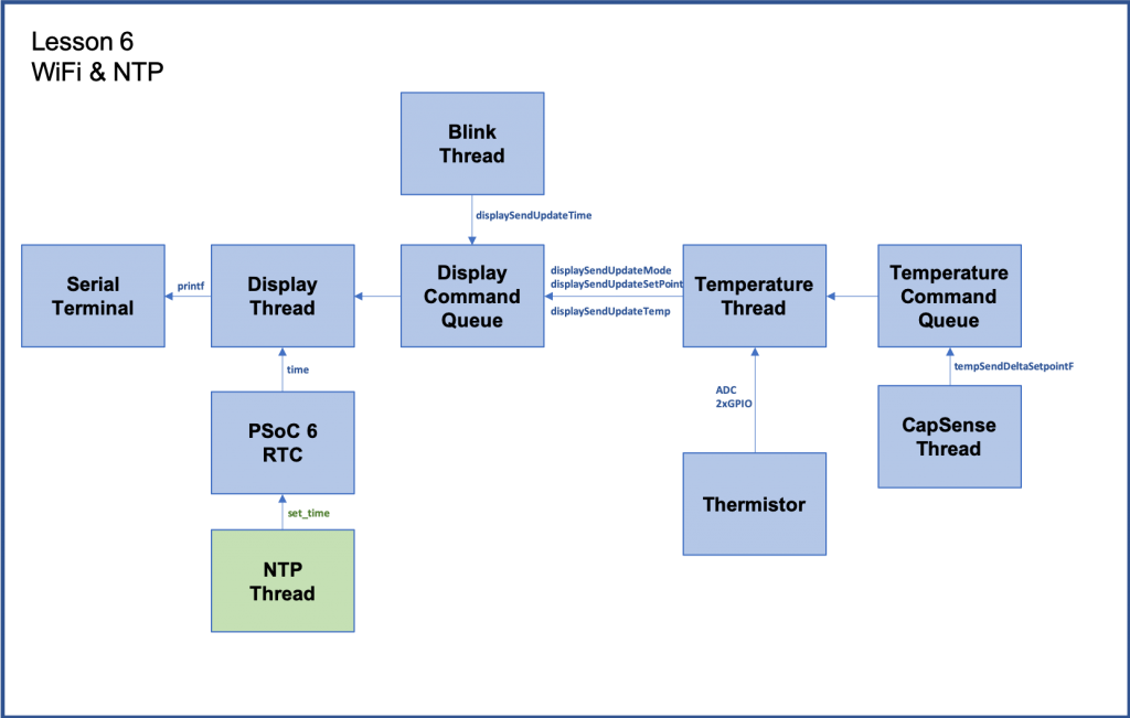
The final architecture of the thermostat looks like this.


Summary

I don’t know about you guys, but it annoys me every time I see that the clock isn’t set.  In this lesson we will start the IoT-ifying of this system by attaching it to WiFi and getting the network time.

Inside of the PSoC is a RealTime clock that is driven by the crystal oscillator on the board.  However, “What time is it?”  turns out to be a pretty simple question to answer if you are attached to the network.  You find out using an NTP server.  This lesson will attach to WiFi, and then every 5 minutes go get the UTC time from an NTP server.

To implement this I will

  1. Import lesson05
  2. Add the NTP Server Library
  3. Create & Code ntpThread.h
  4. Create & Code ntpThread.cpp
  5. Update main.cpp
  6. Build, Program and Test

Import lesson05

First import the Lesson 05 to create a new project.

https://github.com/iotexpert/mouser-mbed-05.git

Add the NTP Server Library

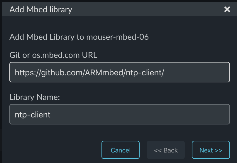
For this lesson I will use a library that knows how to talk to an NTP server using a TCP socket.  To get this library click on the libraries tab and press “+”

Now provide the path to the library.

https://github.com/ARMmbed/ntp-client

Use the master branch:

Create & Code ntpThread.h

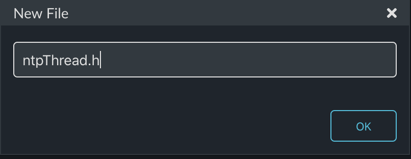
As always I am going to run the NTP Client in a thread.  This thread will be called “ntpThread”:

There is nothing to this but the function definition:

#ifndef NTP_THREAD_H
#define NTP_THREAD_H
void ntpThread();

#endif

Create & Code ntpThread.cpp

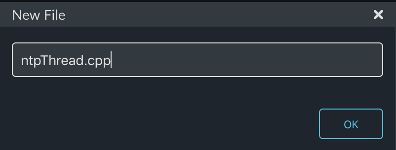
Next create the actual thread code:

This code will need to include the ntp-client library.  Then I do something semi-evil by making an external reference to the WiFiInterface which will be declared in main.cpp.

Finally I will poll the NTP server every 5 minutes.  Notice that if the thing fails it tries again in 10 seconds.  When I get the time I write it into the RTC using the standard-C set_time function.  This function was connected by Cypress to the RTC hardware in the PSoC 6.

#include "mbed.h"
#include "ntp-client/NTPClient.h"

extern WiFiInterface *wifi;


void ntpThread()
{
    NTPClient ntpclient(wifi);
 
    uint32_t sleepTime = 1000 * 60 * 5 ; // 5 minutes
    while(1)
    {

        if(wifi->get_connection_status() == NSAPI_STATUS_GLOBAL_UP)
        {
            time_t timestamp = ntpclient.get_timestamp();
            if (timestamp < 0) {
                sleepTime = 1000 * 10 ; // 10 seconds
            } 
            else 
            {
                set_time(timestamp);
                sleepTime = 1000 * 60 * 5 ; // 5 minutes

            }
        }
        ThisThread::sleep_for(sleepTime); // Goto the NTP server every 5 minutes
    }
}

Update main.cpp

Now I need to update main.cpp.  This time is a little bit different since I need to setup a connection to the WiFi network.  I start by getting a pointer to the WiFi in the system and then connecting before I start all of the threads.

Notice that I hard-coded the SSID and Password.  I also try again until I have a WiFi connection.

The rest of main.cpp is normal.

#include "mbed.h"
#include "blinkThread.h"
#include "displayThread.h"
#include "temperatureThread.h"
#include "capsenseThread.h"
#include "ntpThread.h"

Thread blinkThreadHandle;
Thread displayThreadHandle;
Thread temperatureThreadHandle;
Thread capsenseThreadHandle;
Thread ntpThreadHandle;

WiFiInterface *wifi;

int main()
{

    printf("Started System\n");

    int ret;
    wifi = WiFiInterface::get_default_instance();

    do {
            ret = wifi->connect("CYFI_IOT_EXT", "cypresswicedwifi101", NSAPI_SECURITY_WPA_WPA2);
            if (ret != 0) {
            ThisThread::sleep_for(2000); // If for some reason it doesnt work wait 2s and try again
            }
    } while(ret !=0);


    ntpThreadHandle.start(ntpThread);
    blinkThreadHandle.start(blinkThread);
    displayThreadHandle.start(displayThread);
    temperatureThreadHandle.start(temperatureThread);
    capsenseThreadHandle.start(capsenseThread);
    
}

Build, Program and Test

Now when I program this version, after 10 seconds or so, my time is updated… how cool is that?

Mouser PSoC 6 WiFi/BT MBED: L5 CapSense Thread

IoT Design with Cypress PSoC® 6 MCUs and Wi-Fi/Bluetooth using Arm® Mbed™

# Lesson GitHub Project
0 Introduction
1 Developer Resources
2 Your First Project & The Blinking Thread https://github.com/iotexpert/mouser-mbed-02.git
3 Display Thread https://github.com/iotexpert/mouser-mbed-03.git
4 Temperature Thread https://github.com/iotexpert/mouser-mbed-04.git
5 CapSense Thread https://github.com/iotexpert/mouser-mbed-05.git
6 WiFi & NTP Thread https://github.com/iotexpert/mouser-mbed-06.git
7 The CY8CKIT-062-WiFi-BT https://github.com/iotexpert/mouser-mbed-07.git 
8 Amazon AWS MQTT Thread - Part1 https://github.com/iotexpert/mouser-mbed-08.git
9 Amazon AWS MQTT Thread - Part2 https://github.com/iotexpert/mouser-mbed-09.git

You can “mbed import https://github.com/iotexpert/mouser-mbed-09.git“ to make a copy of the project in your workspace.

The final architecture of the thermostat looks like this.


Summary

In Lesson 05 we will add a CapSense GUI to enable the user to change the setPoint of the thermostat.

Specifically I will create a new Thread called “CapSense Thread” which will read the state of the CapSense Buttons and send messages to the temperatureThread.

To implement this I will:

  1. Import Lesson 04
  2. Add the Cypress CapSense library
  3. Run the CapsSense configurator
  4. Create and code capsenseThread.h
  5. Create and code capsenseThread.cpp
  6. Update main.cpp
  7. Build, Program and Test

Import Lesson 04

First import Lesson 04 and call your new project “mouser-mbed-05”

https://github.com/iotexpert/mouser-mbed-04.git

Add the Cypress CapSense library

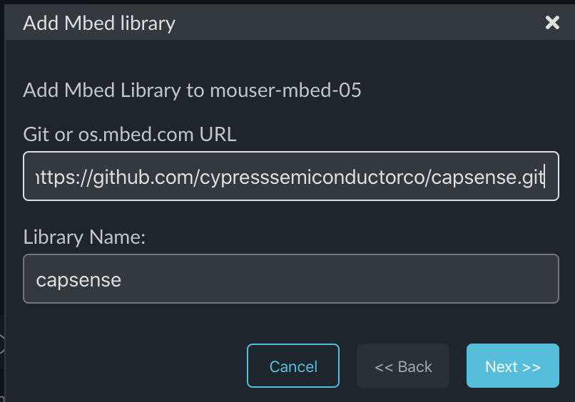
In order to use the CapSense library you will need to import it from the Cypress GitHub site.  To do this we will use the Mbed Studio Library manager.  Click on the “Libraries” tab. Then press the “+” button to add a new library.

Give the Library manager the URL to the Cypress CapSense library:

https://github.com/cypresssemiconductorco/capsense.git

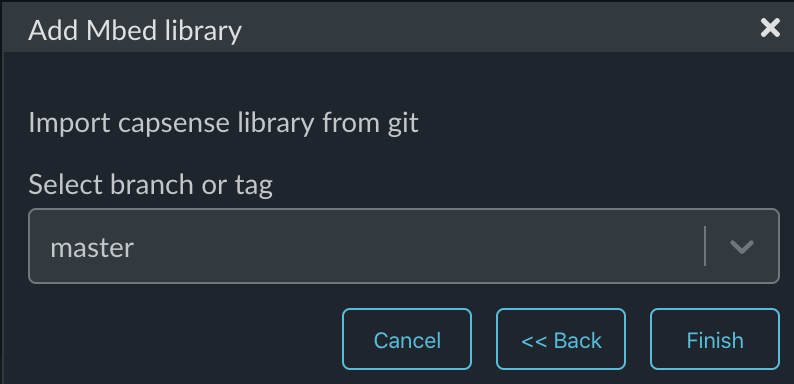
Specify that you want your library to point to the master branch.

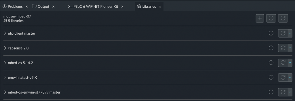
Once that is done your library screen should look something like this.  When I took this screen shot I noticed that I was on the old version of mbed-os so I pressed the update button.

Now both libraries are at the latest version.

Run the CapSense Configurator

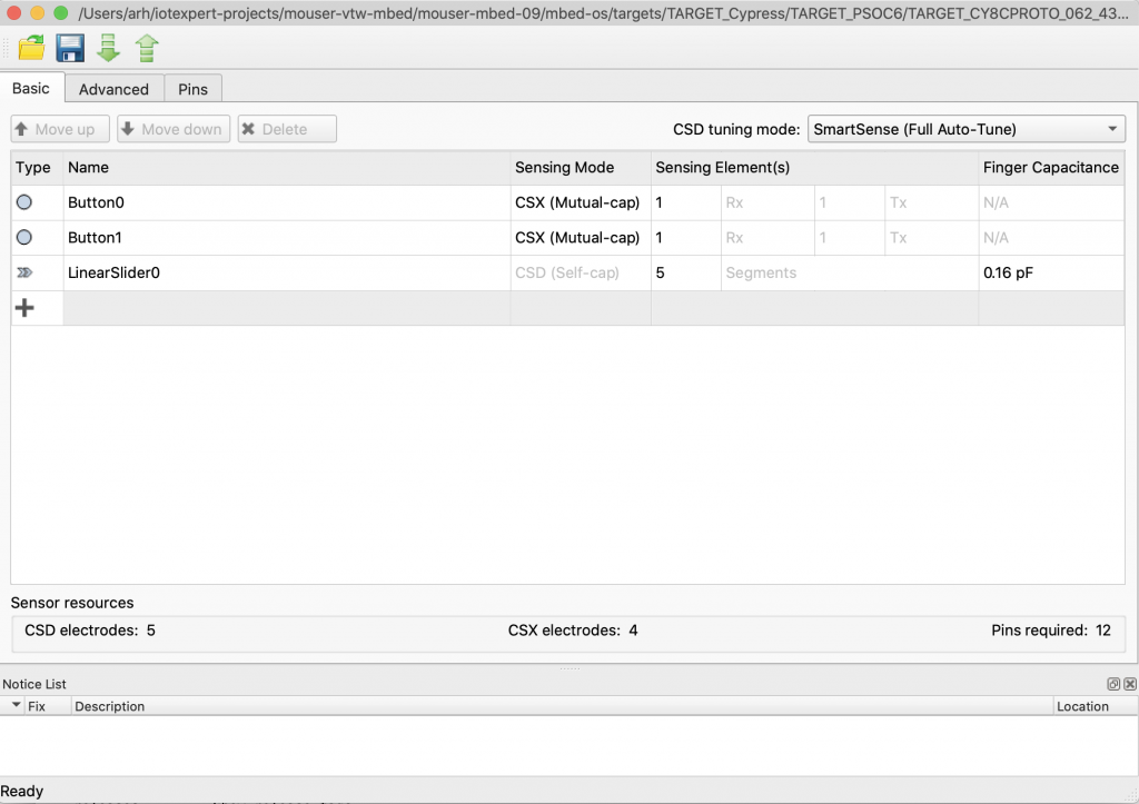
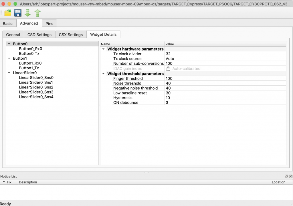
First, lets run the CapSense configurator to look at the CapSense configuration.  You can find it in ModusToolbox/tools_2.0/capsense_configurator. Then use file>open to open the Target’s CapSense configuration file from targets/TARGET_Cypress/TARGET_PSOC6/TARGET_CY8PROTO_062_4343w/COMPONENT_BSP_DESIGN_MODUS/design.cycapsense.

Here is the advanced tab:

The BSP/Target as delivered inside of Mbed OS does not have the generated source code required to run CapSense.  I could press save in the CapSense configurator GUI, but this would modify my version of Mbed OS.  I would rather add these files to the make project.  In order to get this code into my project I run the CapSense Configurator from the command line and tell to save the files locally.

  • /Applications/ModusToolbox/tools_2.0/capsense-configurator/capsense-configurator-cli -c mbed-os/targets/TARGET_Cypress/TARGET_PSOC6/TARGET_CY8CKIT_062_WIFI_BT/COMPONENT_BSP_DESIGN_MODUS/design.cycapsense -o `pwd` -g

Here is what the output looks like:

Create and Code capsenseThread.h

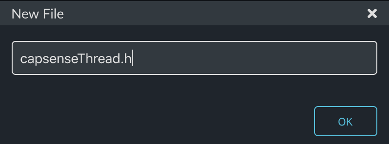
As with all of the other lessons, I want a new thread called “capsenseThread”  Start by making the “dot h”

This will only have the capsenseThread function.

#ifndef CAPSENSE_THREAD_H
#define CAPSENSE_THREAD_H

void capsenseThread(void);

#endif

Create and code capsenseThread.cpp

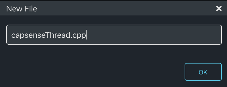
Now make the cpp file.

The Cypress CapSense system is a combination of hardware and firmware.  It works by:

  1. Initializing the Hardware
  2. Initializing the Interrupt
  3. Initializing the callback
  4. Starting a scan (run the hardware block)
  5. Processing the raw data when the scan is done and send a message
  6. Starting another Scan

I got the basis for this code by using the CapSense example project that Cypress has posted on GitHub. You can find that code example at:

github.com/cypresssemiconductorco/mtb-example-psoc6-capsense-buttons-slider

Initializing the Hardware

    /* Configure AMUX bus for CapSense */
    init_cycfg_routing();
    /* Configure PERI clocks for CapSense */
    Cy_SysClk_PeriphAssignDivider(PCLK_CSD_CLOCK, CYBSP_CSD_CLK_DIV_HW, CYBSP_CSD_CLK_DIV_NUM);
    Cy_SysClk_PeriphDisableDivider(CYBSP_CSD_CLK_DIV_HW, CYBSP_CSD_CLK_DIV_NUM);
    Cy_SysClk_PeriphSetDivider(CYBSP_CSD_CLK_DIV_HW, CYBSP_CSD_CLK_DIV_NUM, 0u);
    Cy_SysClk_PeriphEnableDivider(CYBSP_CSD_CLK_DIV_HW, CYBSP_CSD_CLK_DIV_NUM);
    

    /* Initialize the CSD HW block to the default state. */
    Cy_CapSense_Init(&cy_capsense_context);

Initializing the Interrupt

This sets up the CapSense interrupt to work with the hardware block

    const cy_stc_sysint_t CapSense_ISR_cfg =
    {
        .intrSrc = CYBSP_CSD_IRQ,
        .intrPriority = 4u
    };
    /* Initialize CapSense interrupt */
    Cy_SysInt_Init(&CapSense_ISR_cfg, &CapSense_InterruptHandler);
    NVIC_ClearPendingIRQ(CapSense_ISR_cfg.intrSrc);
    NVIC_EnableIRQ(CapSense_ISR_cfg.intrSrc);

Initializing the callback

The callback is used to set the semaphore when the scan is done.

    /* Initialize the CapSense firmware modules. */
    Cy_CapSense_Enable(&cy_capsense_context);
    Cy_CapSense_RegisterCallback(CY_CAPSENSE_END_OF_SCAN_E, CapSenseEndOfScanCallback, &cy_capsense_context);

Starting a scan (run the hardware block)

    Cy_CapSense_ScanAllWidgets(&cy_capsense_context);  // Launch the initial scan   

Processing Raw Data when the scan completes, and Send Message

        if (CY_CAPSENSE_NOT_BUSY == Cy_CapSense_IsBusy(&cy_capsense_context))
        {
            Cy_CapSense_ProcessAllWidgets(&cy_capsense_context);
            uint32_t currBtn0Status = Cy_CapSense_IsSensorActive(CY_CAPSENSE_BUTTON0_WDGT_ID, CY_CAPSENSE_BUTTON0_SNS0_ID, &cy_capsense_context);        
            uint32_t currBtn1Status = Cy_CapSense_IsSensorActive(CY_CAPSENSE_BUTTON1_WDGT_ID, CY_CAPSENSE_BUTTON1_SNS0_ID, &cy_capsense_context);       

            if(currBtn0Status != prevBtn0Status && currBtn0Status==1 )
            {
                tempSendDeltaSetpointF(-0.1);
            }
            prevBtn0Status = currBtn0Status;
    
            if(currBtn1Status != prevBtn1Status && currBtn1Status == 1)
            {
                tempSendDeltaSetpointF(0.1);
            } 
            prevBtn1Status = currBtn1Status;

             
        } 

Starting another Scan

Cy_CapSense_ScanAllWidgets(&cy_capsense_context);

Here is the whole file:

#include "mbed.h"
#include "cy_pdl.h"
#include "cycfg_capsense.h"
#include "cycfg.h"
#include "temperatureThread.h"

static Semaphore capsense_sem;


/*****************************************************************************
* Function Name: CapSense_InterruptHandler()
******************************************************************************
* Summary:
*  Wrapper function for handling interrupts from CSD block.
*
*****************************************************************************/
static void CapSense_InterruptHandler(void)
{
    Cy_CapSense_InterruptHandler(CYBSP_CSD_HW, &cy_capsense_context);
}


/*****************************************************************************
* Function Name: CapSenseEndOfScanCallback()
******************************************************************************
* Summary:
*  This function releases a semaphore to indicate end of a CapSense scan.
*
* Parameters:
*  cy_stc_active_scan_sns_t* : pointer to active sensor details.
*
*****************************************************************************/
static void CapSenseEndOfScanCallback(cy_stc_active_scan_sns_t * ptrActiveScan)
{
    capsense_sem.release();
}


void capsenseThread(void)
{

    /* Configure AMUX bus for CapSense */
    init_cycfg_routing();
    /* Configure PERI clocks for CapSense */
    Cy_SysClk_PeriphAssignDivider(PCLK_CSD_CLOCK, CYBSP_CSD_CLK_DIV_HW, CYBSP_CSD_CLK_DIV_NUM);
    Cy_SysClk_PeriphDisableDivider(CYBSP_CSD_CLK_DIV_HW, CYBSP_CSD_CLK_DIV_NUM);
    Cy_SysClk_PeriphSetDivider(CYBSP_CSD_CLK_DIV_HW, CYBSP_CSD_CLK_DIV_NUM, 0u);
    Cy_SysClk_PeriphEnableDivider(CYBSP_CSD_CLK_DIV_HW, CYBSP_CSD_CLK_DIV_NUM);
    

    /* Initialize the CSD HW block to the default state. */
    Cy_CapSense_Init(&cy_capsense_context);

    const cy_stc_sysint_t CapSense_ISR_cfg =
    {
        .intrSrc = CYBSP_CSD_IRQ,
        .intrPriority = 4u
    };
    /* Initialize CapSense interrupt */
    Cy_SysInt_Init(&CapSense_ISR_cfg, &CapSense_InterruptHandler);
    NVIC_ClearPendingIRQ(CapSense_ISR_cfg.intrSrc);
    NVIC_EnableIRQ(CapSense_ISR_cfg.intrSrc);

    /* Initialize the CapSense firmware modules. */
    Cy_CapSense_Enable(&cy_capsense_context);
    Cy_CapSense_RegisterCallback(CY_CAPSENSE_END_OF_SCAN_E, CapSenseEndOfScanCallback, &cy_capsense_context);

    Cy_CapSense_ScanAllWidgets(&cy_capsense_context);  // Launch the initial scan   
    
    uint32_t prevBtn0Status = 0u; 
    uint32_t prevBtn1Status = 0u;
     
    while(1)
    {

        capsense_sem.acquire();
        if (CY_CAPSENSE_NOT_BUSY == Cy_CapSense_IsBusy(&cy_capsense_context))
        {
            Cy_CapSense_ProcessAllWidgets(&cy_capsense_context);
            uint32_t currBtn0Status = Cy_CapSense_IsSensorActive(CY_CAPSENSE_BUTTON0_WDGT_ID, CY_CAPSENSE_BUTTON0_SNS0_ID, &cy_capsense_context);        
            uint32_t currBtn1Status = Cy_CapSense_IsSensorActive(CY_CAPSENSE_BUTTON1_WDGT_ID, CY_CAPSENSE_BUTTON1_SNS0_ID, &cy_capsense_context);       

            if(currBtn0Status != prevBtn0Status && currBtn0Status==1 )
            {
                tempSendDeltaSetpointF(-0.1);
            }
            prevBtn0Status = currBtn0Status;
    
            if(currBtn1Status != prevBtn1Status && currBtn1Status == 1)
            {
                tempSendDeltaSetpointF(0.1);
            } 
            prevBtn1Status = currBtn1Status;

            Cy_CapSense_ScanAllWidgets(&cy_capsense_context);  
        } 

    }
}

Update main.cpp

Inside of the main.cpp I will make the usual changes to turn on the CapSense thread.

#include "mbed.h"
#include "blinkThread.h"
#include "displayThread.h"
#include "temperatureThread.h"
#include "capsenseThread.h"

Thread blinkThreadHandle;
Thread displayThreadHandle;
Thread temperatureThreadHandle;
Thread capsenseThreadHandle;

int main()
{

    printf("Started System\n");

    blinkThreadHandle.start(blinkThread);
    displayThreadHandle.start(displayThread);
    temperatureThreadHandle.start(temperatureThread);
    capsenseThreadHandle.start(capsenseThread);

}

Build, Program and Test

When I build, program and test I can see that by pressing the two CapSense Buttons I can raise and lower the setPoint.

Mouser PSoC 6 WiFi/BT MBED: L7 The CY8CKIT-062-WiFi-BT

IoT Design with Cypress PSoC® 6 MCUs and Wi-Fi/Bluetooth using Arm® Mbed™

# Lesson GitHub Project
0 Introduction
1 Developer Resources
2 Your First Project & The Blinking Thread https://github.com/iotexpert/mouser-mbed-02.git
3 Display Thread https://github.com/iotexpert/mouser-mbed-03.git
4 Temperature Thread https://github.com/iotexpert/mouser-mbed-04.git
5 CapSense Thread https://github.com/iotexpert/mouser-mbed-05.git
6 WiFi & NTP Thread https://github.com/iotexpert/mouser-mbed-06.git
7 The CY8CKIT-062-WiFi-BT https://github.com/iotexpert/mouser-mbed-07.git 
8 Amazon AWS MQTT Thread - Part1 https://github.com/iotexpert/mouser-mbed-08.git
9 Amazon AWS MQTT Thread - Part2 https://github.com/iotexpert/mouser-mbed-09.git

You can “mbed import https://github.com/iotexpert/mouser-mbed-09.git“ to make a copy of the project in your workspace.

The final architecture of the thermostat looks like this.


Summary

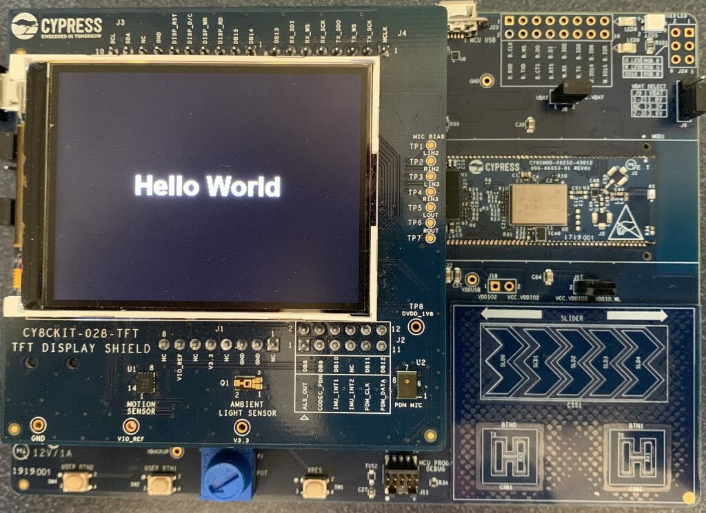
This weekend as I was getting ready for the workshop, my son, Nicholas, was making fun of me for my user interface.  To fix this I decided to show how you could move platforms.  Specifically to the CY8CKIT-062-WiFi-BT which you can buy from mouser.com

You could literally just change the target and things would work… almost.  The one exception is that this development kit doesn’t have a thermistor.  So, I soldered a different kind of temperature sensor, called a TMP36, onto the kit which means I have to make a few small code updates to the temperatureThread.

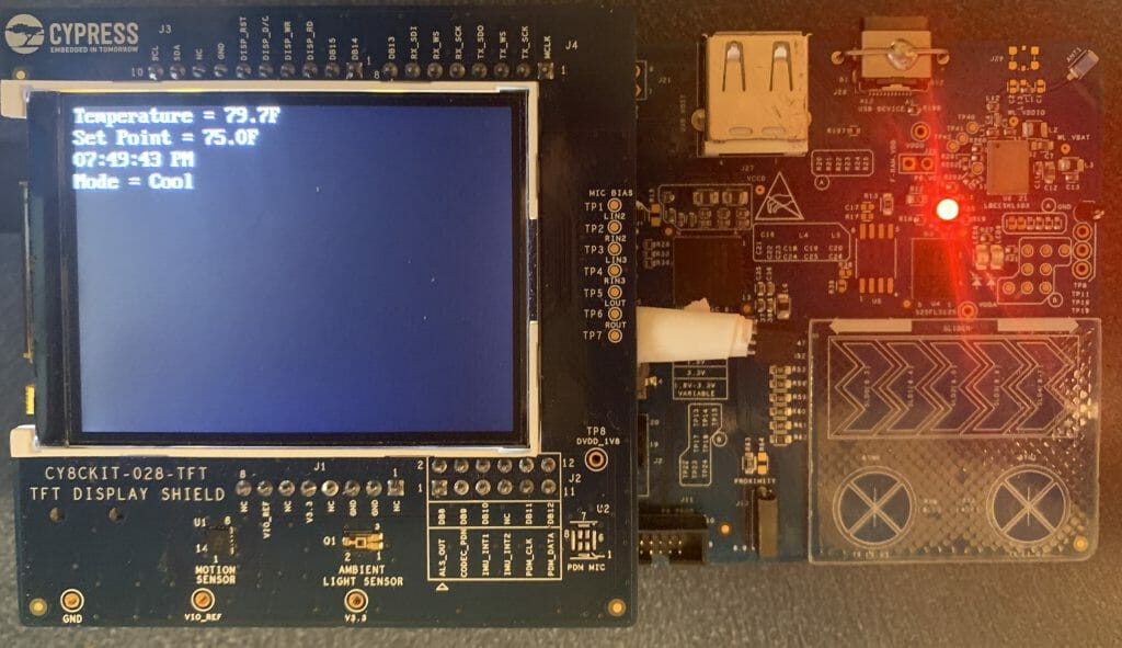
In addition to changing to the TMP36 I will also use the TFT as a display for the system, so I need to modify the displayThread.

One of the major points that I wanted to make with this lesson is that if you design your code correctly, a change like this isn’t very hard.

To implement this I will:

  1. Provide a TMP36 Temperature Sensor Tutorial
  2. Modify the CY8CKIT-028-TFT
  3. Import Lesson06
  4. Update temperatureThread.cpp
  5. Build, Program and Test
  6. Add Segger emWin Library
  7. Add IoTExpert CY8CKIT-028-TFT configuration
  8. Update mbed_app.json to include driver
  9. Update displayThread.cpp
  10. Build, Program and Test

TMP36 Temperature Sensor

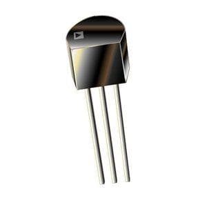
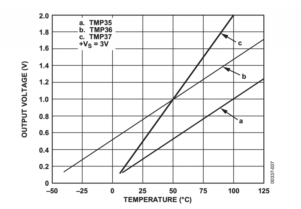
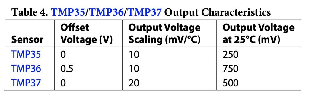
The TMP36 is a single wire temperature sensor that gives you a voltage that is directly proportional to the temperature.  Specifically, it is 10mV per degree C.

The Analog Devices TMP36 that I am using I bought here from mouser.com.  It looks like a little 3-wire transistor looking thing.

Here is a snapshot from the data sheet of the temperature voltage response

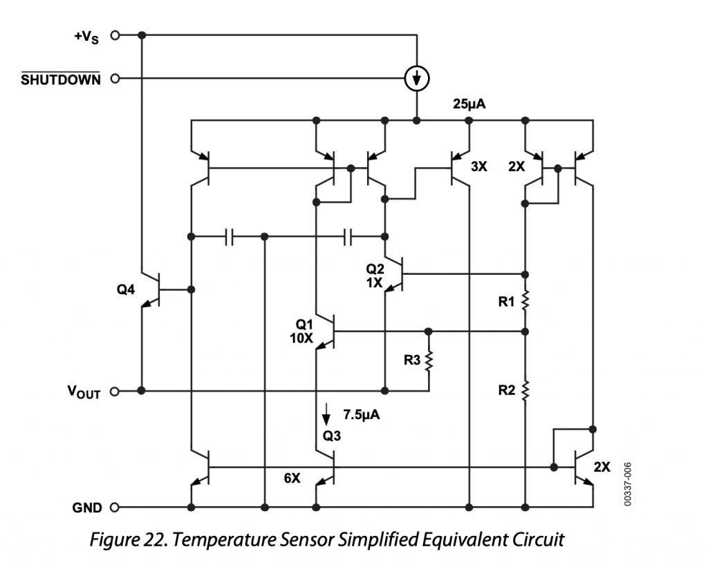
Yes I know that I am a digital guy, but for just three wires, signal, ground and power, it sure looks like there is a lot going on in the package.

The data sheet (which is actually really interesting)  gives you the parameters to make the linear equation for temperature

To calculate the temperature you just calculate:

T = (degree C/10mV) * V – 50 degree C

Here is the function to read the temperature:

static AnalogIn tmp36(A5);
static void readTemp()
{
    float volts;
    
    volts = tmp36.read() * 2.4;
    float temperatureC = 1/.01 * volts - 50.0;
    temperatureF = (temperatureC * 9.0/5.0) + 32;
}

Modify the CY8CKIT-028-TFT

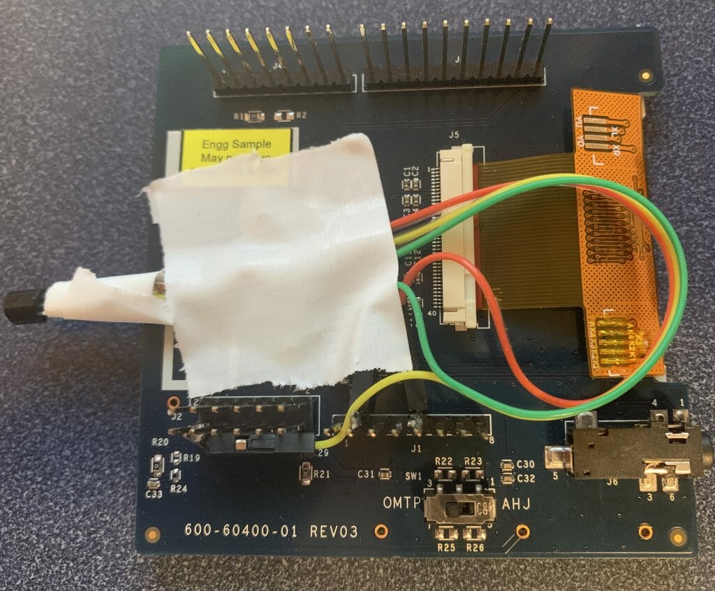
Start this process by attaching the TMP36.  On the back of the CY8CKIT-028-TFT I solder three wires onto the temperature sensor.  One to 3.3v, one to ground and one to A5.  Here is the picture of my ugly ugly solder job.  Yes, that is duct-tape holding it onto the back of the shield.  And yes that is a prototype sticker.

I also remove the PDM microphone which is also attached to A5 (I’m not sure that it would cause a problem… but better safe than sorry)

Import Lesson06

Now, fix the code.  As always, start by importing the previous lesson.

https://github.com/iotexpert/mouser-mbed-06.git

Update temperatureThread.cpp

In order to switch between the thermistor and the TMP36 I create two #defines based on the target that is currently active.  This is cool because the Mbed OS creates these #defines automatically.

#ifdef TARGET_CY8CPROTO_062_4343W
#define THERMISTOR
#endif

#ifdef TARGET_CY8CKIT_062_WIFI_BT
#define TMP36
#endif

There are a bunch of ways that could have been done, including with the Mbed configuration system which you control with the mbed_app.json.  But this was expedient.

Next, I create the code to measure the temperature using the AnalogIn object. Notice that it is connected to the Arduino A5 pin. Also notice that when the TMP36 is active I have a different readTemp function so I don’t need to change anything else to get the temperature.

#ifdef TMP36
static AnalogIn tmp36(A5);
static void readTemp()
{
    float volts;
    
    volts = tmp36.read() * 2.4;
    float temperatureC = 1/.01 * volts - 50.0; // from the data sheet
    temperatureF = (temperatureC * 9.0/5.0) + 32; // conver to F
}
#endif

Then I update the thermistor readTemp function with the THERMISTOR #define

#ifdef THERMISTOR
static DigitalOut thermVDD(P10_3,1);
static DigitalOut thermGND(P10_0,0);
static AnalogIn thermOut(P10_1);

static void readTemp()
{
    float refVoltage = thermOut.read() * 2.4; // Range of ADC 0->2*Vref
    float refCurrent = refVoltage  / 10000.0; // 10k Reference Resistor
    float thermVoltage = 3.3 - refVoltage;    // Assume supply voltage is 3.3v
    float thermResistance = thermVoltage / refCurrent; 
    float logrT = (float32_t)log((float64_t)thermResistance);

    /* Calculate temperature from the resistance of thermistor using Steinhart-Hart Equation */
    float stEqn = (float32_t)((0.0009032679) + ((0.000248772) * logrT) + 
                             ((2.041094E-07) * pow((float64)logrT, (float32)3)));

    float temperatureC = (float32_t)(((1.0 / stEqn) - 273.15)  + 0.5);
    temperatureF = (temperatureC * 9.0/5.0) + 32;
}
#endif

Here is the whole file:

#include "mbed.h"
#include "temperatureThread.h"
#include "displayThread.h"


#ifdef TARGET_CY8CPROTO_062_4343W
#define THERMISTOR
#endif

#ifdef TARGET_CY8CKIT_062_WIFI_BT
#define TMP36
#endif


static float temperatureF;
static float setPoint = 75.0;

static void readTemp();

typedef enum {
    CMD_setPointDelta,
    CMD_setPoint,

} command_t;


typedef struct {
    command_t cmd;
    float    value;   /* AD result of measured voltage */
} msg_t;


static Queue<msg_t, 32> queue;
static MemoryPool<msg_t, 16> mpool;

void tempSendDeltaSetpointF(float delta)
{
    msg_t *message = mpool.alloc();
    if(message)
    {
        message->cmd = CMD_setPointDelta;
        message->value = delta;
        queue.put(message);
    }
}

void tempSendUpdateCurrentSetPointF(float setPoint)
{
    msg_t *message = mpool.alloc();
    if(message)
    {
        message->cmd = CMD_setPoint;
        message->value = setPoint;
        queue.put(message);
    }
}

void temperatureThread()
{

    char buffer[128];
    displaySendUpdateTemp(temperatureF);
    displaySendUpdateSetPoint(setPoint);
    
    while(1)
    {
        osEvent evt = queue.get(200);
        if (evt.status == osEventMessage) {
            msg_t *message = (msg_t*)evt.value.p;
            switch(message->cmd)
            {
                case CMD_setPointDelta:
                    setPoint += message->value;
                    displaySendUpdateSetPoint(setPoint);
                break;
                case CMD_setPoint:
                    setPoint = message->value;
                    displaySendUpdateSetPoint(setPoint);
                break;

            }
            mpool.free(message);

        }
        else
        {
            readTemp();

            // Control the HVAC system with +- 0.5 degree of Hystersis
            if(temperatureF < setPoint - 0.5)
                displaySendUpdateMode(-1.0);
            else if (temperatureF > setPoint + 0.5)
                displaySendUpdateMode(1.0);
            else
                displaySendUpdateMode(0.0);

            displaySendUpdateTemp(temperatureF);
        
        }
    }

}


#ifdef THERMISTOR
static DigitalOut thermVDD(P10_3,1);
static DigitalOut thermGND(P10_0,0);
static AnalogIn thermOut(P10_1);

static void readTemp()
{
    float refVoltage = thermOut.read() * 2.4; // Range of ADC 0->2*Vref
    float refCurrent = refVoltage  / 10000.0; // 10k Reference Resistor
    float thermVoltage = 3.3 - refVoltage;    // Assume supply voltage is 3.3v
    float thermResistance = thermVoltage / refCurrent; 
    float logrT = (float32_t)log((float64_t)thermResistance);

    /* Calculate temperature from the resistance of thermistor using Steinhart-Hart Equation */
    float stEqn = (float32_t)((0.0009032679) + ((0.000248772) * logrT) + 
                             ((2.041094E-07) * pow((float64)logrT, (float32)3)));

    float temperatureC = (float32_t)(((1.0 / stEqn) - 273.15)  + 0.5);
    temperatureF = (temperatureC * 9.0/5.0) + 32;
}
#endif

#ifdef TMP36
static AnalogIn tmp36(A5);
static void readTemp()
{
    float volts;
    
    volts = tmp36.read() * 2.4;
    float temperatureC = 1/.01 * volts - 50.0;
    temperatureF = (temperatureC * 9.0/5.0) + 32;
}
#endif

Build, Program and Test

With that little update I can now build, program and test. Notice that my display is still working… and I can change the temperature by holding the TMP36 between my fingers.

Add Segger emWin Library

But, I haven’t really addressed Nicholas’ complaint, the GUI.  To do this I am going to use the Segger emWin library to control the TFT display.  Go to the library manager and add the library.

https://github.com/cypresssemiconductorco/emwin.git

Use the master branch:

Add IoTExpert CY8CKIT-028-TFT configuration

The emWin library doesn’t know anything about how the TFT is attached.  So, I created a driver library which you can use for all of the Cypress development kits.

https://github.com/iotexpert/mbed-os-emwin-st7789v.git

Use the master branch:

Now your libraries should look like this.

Update mbed_app.json to include emWin Driver

In order to use this driver you need to tell Mbed OS to add the correct archive file.  To do this update mbed_app.json

{
    "target_overrides": {
        "*": {
            "target.components_add": ["EMWIN_OSNTS"],
            "platform.stdio-baud-rate": 115200
        }
    }
}

Update displayThread.cpp

Finally update the displayThread.  Start by adding the include for the Segger library.

#ifdef TARGET_CY8CKIT_062_WIFI_BT
#include "GUI.h"
#endif

Then update the displayAtXY function to also print on the display.  By doing it here I don’t have to change anything else in the code because this is the only function that draws on the screen.

static void displayAtXY(int x, int y,char *buffer)
{
    #ifdef TARGET_CY8CKIT_062_WIFI_BT
    GUI_SetTextAlign(GUI_TA_LEFT);
    GUI_DispStringAt(buffer,(x-1)*8,(y-1)*16); // 8x16 font
    #endif
    // row column
    printf("3[%d;%dH%s",y,x,buffer);
    fflush(stdout);
}

Update the main thread to initialize the display when the thread starts.

void displayThread()
{
    char buffer[128];

    printf("3[2J3[H"); // Clear Screen and go Home
    printf("3[?25l"); // Turn the cursor off
    fflush(stdout);

    #ifdef TARGET_CY8CKIT_062_WIFI_BT
        GUI_Init();
        GUI_SetColor(GUI_WHITE);
        GUI_SetBkColor(GUI_BLACK);
        GUI_SetFont(GUI_FONT_8X16_1);
    #endif

Build, Program and Test

When you program, now you should have a TFT display.  Happy Nicholas?

Mouser PSoC 6 WiFi/BT MBED: L8 Amazon AWS MQTT Thread – Part1

IoT Design with Cypress PSoC® 6 MCUs and Wi-Fi/Bluetooth using Arm® Mbed™

# Lesson GitHub Project
0 Introduction
1 Developer Resources
2 Your First Project & The Blinking Thread https://github.com/iotexpert/mouser-mbed-02.git
3 Display Thread https://github.com/iotexpert/mouser-mbed-03.git
4 Temperature Thread https://github.com/iotexpert/mouser-mbed-04.git
5 CapSense Thread https://github.com/iotexpert/mouser-mbed-05.git
6 WiFi & NTP Thread https://github.com/iotexpert/mouser-mbed-06.git
7 The CY8CKIT-062-WiFi-BT https://github.com/iotexpert/mouser-mbed-07.git 
8 Amazon AWS MQTT Thread - Part1 https://github.com/iotexpert/mouser-mbed-08.git
9 Amazon AWS MQTT Thread - Part2 https://github.com/iotexpert/mouser-mbed-09.git

You can “mbed import https://github.com/iotexpert/mouser-mbed-09.git“ to make a copy of the project in your workspace.

The final architecture of the thermostat looks like this.


Summary

In this lesson we will plumb in the ability to talk to the Amazon Web Services MQTT broker.  Specifically to publish messages from the broker to change the setPoint of the thermostat.

To implement this I will:

  1. Discuss MQTT
  2. Import Lesson 07
  3. Add the Cypress AWS IoT Middleware
  4. Add the Cypress Connectivity Utilities Library
  5. Create an AWS Policy, Thing, and Certificate
  6. Modify the keys to “C” format
  7. Create and Code awsThread.h
  8. Create and Code awsThread.cpp
  9. Update main.cpp
  10. Build, Program and Test

MQTT

There are five basic ideas that you need to understand when using MQTT.

  • (Message) Broker
  • Topic
  • Subscriber
  • Publisher
  • Messages

The Broker is a TCP/IP server sitting at the middle of an MQTT network.  It is responsible for receiving Messages from Publishers and forwarding them on to Subscribers.  A broker can run multiple simultaneous communication channels called Topics.

Topics are ad-hoc (application semantics) and are just a string of characters … like “setPoint” or “thing/setPoint”

Messages are just a string of bytes.  Typically formatted as JSON.  This is by convention and is not a requirement.

MQTT clients can be Publishers or Subscribers or both.

Import Lesson 07

Start by importing Lesson 07.

https://github.com/iotexpert/mouser-mbed-07.git


Add the Cypress AWS IoT Middleware

Cypress has built a library which will help you manage connections to AWS.  We call it the aws IoT middleware library.  Go to the library manager and add it:

  • https://github.com/cypresssemiconductorco/aws-iot.git

Use the master branch:

Add the Cypress Connectivity Utilities Library

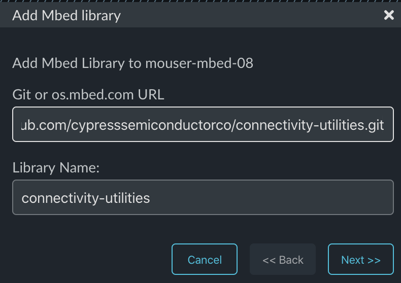
The AWS IoT library needs to use another library of connectivity functions.  Add it:

  • https://github.com/cypresssemiconductorco/connectivity-utilities.git

Select the master branch:

Create an AWS Policy, Thing, and Certificate

In order to make a connection to AWS you need to have a policy attached to a certificate.  In addition it makes sense to have an AWS “Thing” to represent your system.

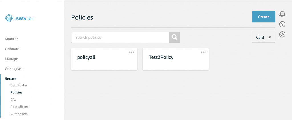
Start from the AWS Console and press “Secure->Policies”.  Then press “Create”

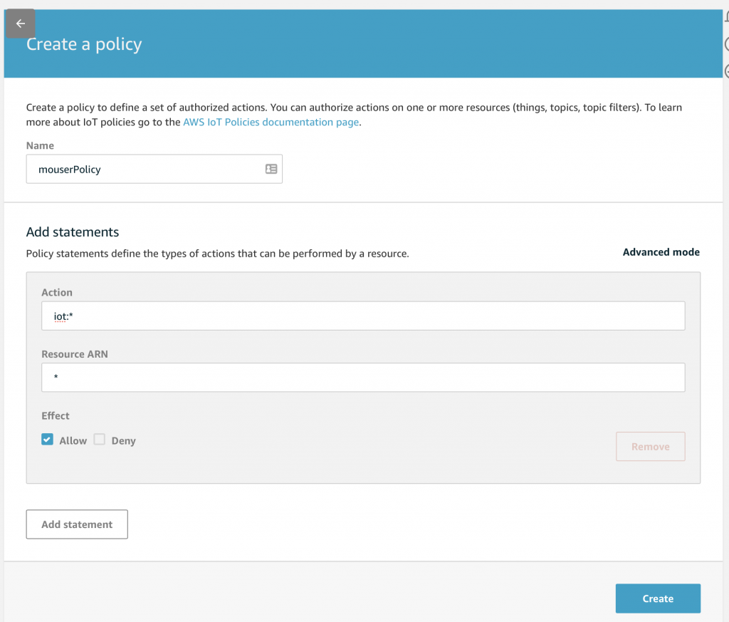
Give your policy a name.  Add all “iot:*” and all resource and “allow”.  Then press “Create”:

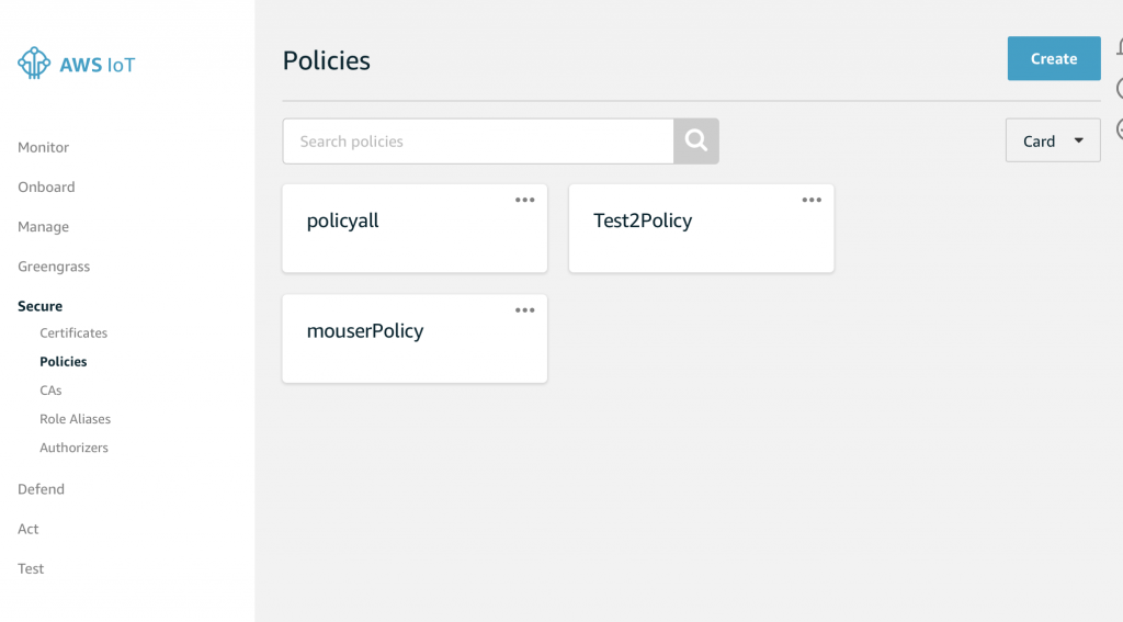
Once the policy is created you will see it in the catalog:

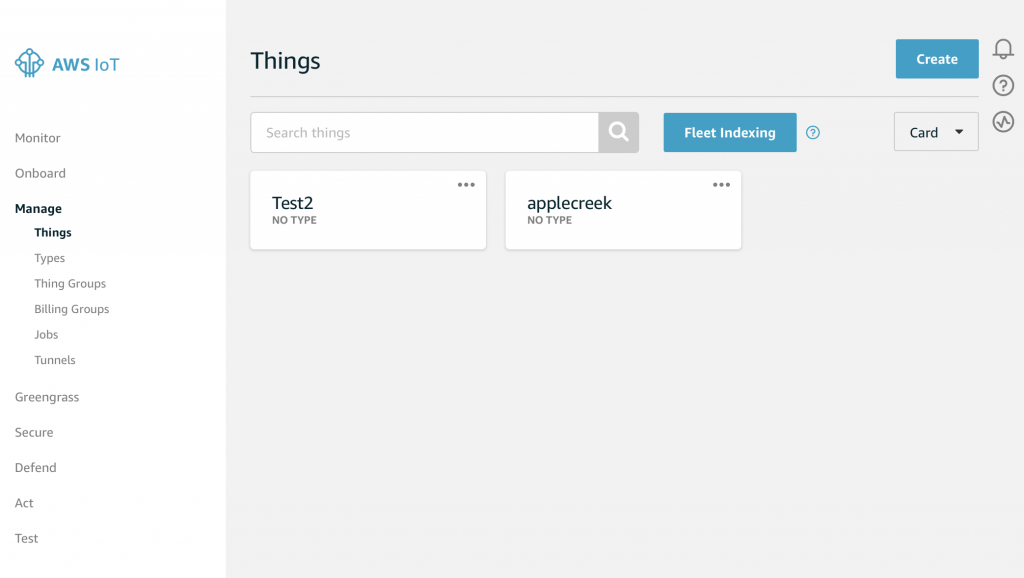
Create a new Thing by clicking “Manage -> Things”.  Then click “Create””

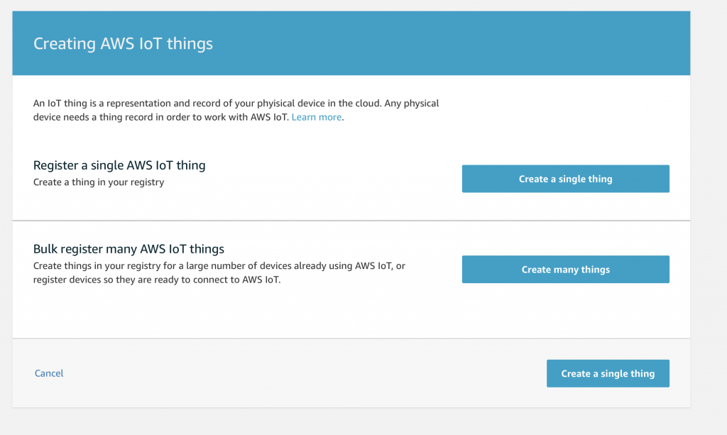
Press “Create a single thing”:

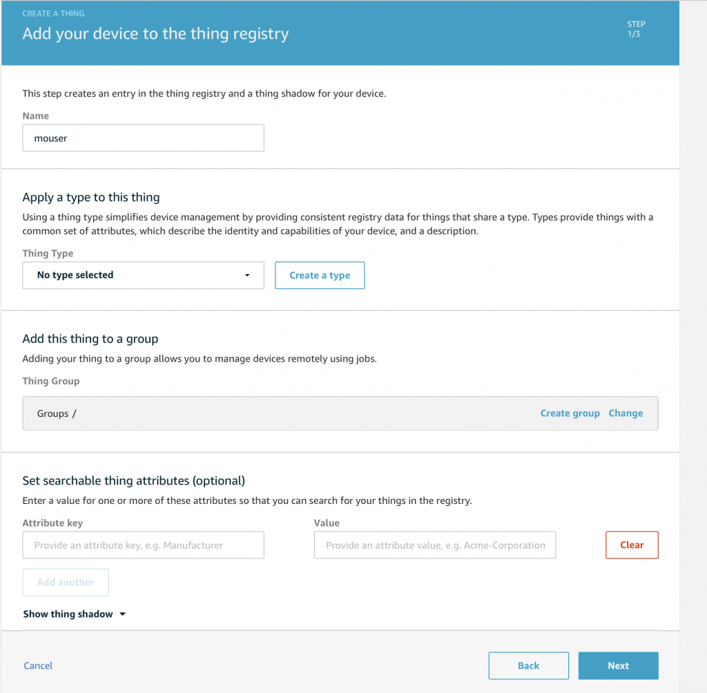
First give your thing a name (in this case mouser) then click “Next”:

Click “Create certificate”

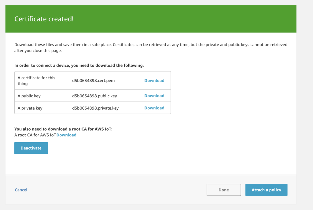
You MUST DOWNLOAD these files now.  You will not be given another chance. Press activate:

Which will show the certificate as active.  Next press “attach a policy”:

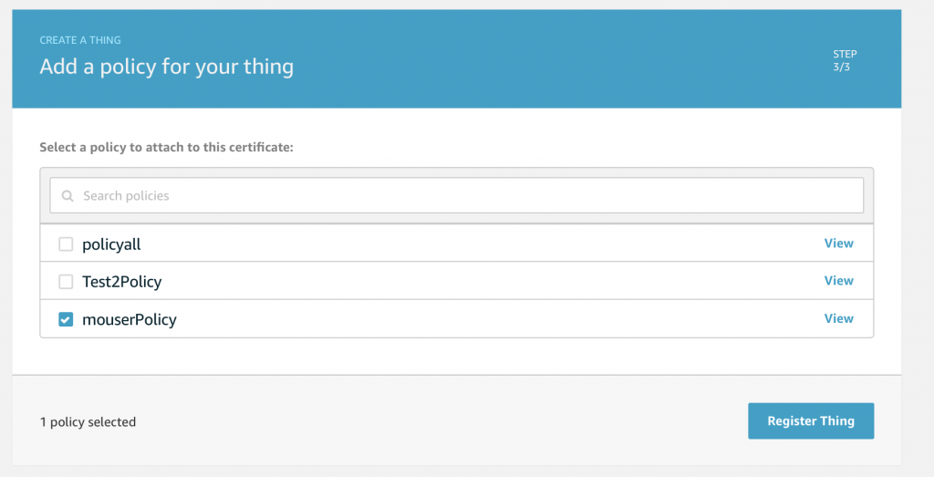
Then pick the Mouser policy:

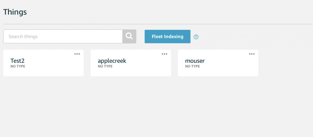
Now you have your new “Thing”.

Modify the keys to “C” Format

In order to make a connection to AWS you need a valid certificate, the private key that goes with the certificate and the CA certificate of AWS.    You just created these files in the previous step.

These keys come looking like this:

-----BEGIN RSA PRIVATE KEY-----
MIIEpQIBAAKCAQEAsRLypD2uhZNZgtfPAuX8M3ZFNYcBU/BHulG9CJrETKwmjXOV
j1l9U/Tlu3p/hGIFEhrkbqt1SGvPEj8x7U5kyCpJde1JojObW4m2S5T7WuXxd5JQ
Y+rqWkyrvwp/1HPFLRB3n3OopGaUcnEZwegsMznUcsi+kZwrUDkqBWFIQbEEKjW8
UzZxqmbmNSCsJQXHCv9OPrKdeisBnkQrpRkTz4uSG3yZI6jG7acx3UZkMcc6DvDo
bbz8PoBisZq4JcKthwpQdiV1RdS4aqCc0wq5Jv7DvhifqNcrOK3PT+zkck82jqIC
VDd58NkY6Y0URIyqjPCPPIltCbrAB/+u41rrtQIDAQABAoIBAQCQAhvprOxpX+u1
OLP35HjWlYI1xSU0Ub7T7bPx8oRg4sS711uz6JC/nfTUIwzf6iO7lLlgs/q/OkZ+
zXxaRZ47GAEEckWnL5dSu83Q7En7o/RcTVcp25xace5fgTdy3fBm9PSEbjih83cZ
F5heFecUhhyceVxa6YpkRQlCtNph6SwFfsY1BmfhHISHh4U7XYityUatdalQfOtL
Vf79TRIE/X1aX/H/xXYsqNQPCSGUzNj1BU5aHOM93B+hNg8q1t+Ze5w6Q/HkMBTb
5VPI8fabvaAV6WUrrWtEl8ErcokutYWNRadXH0ieCGiuI2uoK0qqgrBb2MwZwv81
ZtzCm3QlAoGBAOj5zlZtcWN5Mfb9PHonPSwFPE4pud2fZCJjO9btQWb6ELYwp9qW
2aRaoaQm9bA7pTwMaSRQYGC9eKPu8hu+cqPXJZ1gg1GrYP+IfJMChDAM0x7Faks4
B7ZDjfQlRGUJGAkqLQ4/4+k2y75KtZdnri5Z40myh4f0+PuiDDRwPcGjAoGBAMKS
2VuNefMvzqKW7g/drRLzChudUL96r2BWI8nkl7S9UChtKVgdqJcrNSiKXbTv0wLn
pWsnlOIxPVJAi1u5we045U+ZQadgIg4UqeIBVfRVKm4ZKrInSCT4uMriGDDJuvQl
NXBv9PIX8WCaPWpG2rcsOFsi0mNBcImVHMAhc2LHAoGBAIk6k8Ku5opMWhT9J0Fg
mZSzZMk5pMSZXXcv8pBv4gVRKMTYNhb4oixAQlQZqsBq8bJEMS51tb9l+4i8d5nF
/WrqkLp5ngBeLV13PMGvSsOu2jCW4jx6PXirpBL6XKYSzDihwjZRheLaJvrosLwF
E0E0K0A+y7xWnM5DrmK49nd3AoGAQdp70F24yZMDp8nXdu07F6/EWwZKfxQh6UQe
RsWkhtqQF66ikJ0xI0DPdBIolwWYcGJAfVzfKhMqQv1vbTMYrJZWHjOrod+KhyN9
P+3dzp1IiAzig3uCEmlP+fK95z1PljRFuvFZgNqTqnNpl9+1RMulo0rM1CUg1p/u
JCTuLZ8CgYEAwUsBplIARj4i+hhyVWC1WOR+I4AqgRAauCwliO9gvToJzjkQsc5q
RZxPbXLbm907wy6/7P/tKT20WhZ0b7szZsXchdeX20xSfAa4N0bJTZy3OiS0CYtF
3+Xw1Mlu3Gihr89X9QeSot0tH9m6QZky032aLW/8jbNT3Eb49niqQZA=
-----END RSA PRIVATE KEY-----

But you need them to look like this so that they can be read in by the Mbed TLS library.

// Private key
const char SSL_CLIENTKEY_PEM[] = \
"-----BEGIN RSA PRIVATE KEY-----\n"\
"MIIEpQIBAAKCAQEAsRLypD2uhZNZgtfPAuX8M3ZFNYcBU/BHulG9CJrETKwmjXOV\n"\
"j1l9U/Tlu3p/hGIFEhrkbqt1SGvPEj8x7U5kyCpJde1JojObW4m2S5T7WuXxd5JQ\n"\
"Y+rqWkyrvwp/1HPFLRB3n3OopGaUcnEZwegsMznUcsi+kZwrUDkqBWFIQbEEKjW8\n"\
"UzZxqmbmNSCsJQXHCv9OPrKdeisBnkQrpRkTz4uSG3yZI6jG7acx3UZkMcc6DvDo\n"\
"bbz8PoBisZq4JcKthwpQdiV1RdS4aqCc0wq5Jv7DvhifqNcrOK3PT+zkck82jqIC\n"\
"VDd58NkY6Y0URIyqjPCPPIltCbrAB/+u41rrtQIDAQABAoIBAQCQAhvprOxpX+u1\n"\
"OLP35HjWlYI1xSU0Ub7T7bPx8oRg4sS711uz6JC/nfTUIwzf6iO7lLlgs/q/OkZ+\n"\
"zXxaRZ47GAEEckWnL5dSu83Q7En7o/RcTVcp25xace5fgTdy3fBm9PSEbjih83cZ\n"\
"F5heFecUhhyceVxa6YpkRQlCtNph6SwFfsY1BmfhHISHh4U7XYityUatdalQfOtL\n"\
"Vf79TRIE/X1aX/H/xXYsqNQPCSGUzNj1BU5aHOM93B+hNg8q1t+Ze5w6Q/HkMBTb\n"\
"5VPI8fabvaAV6WUrrWtEl8ErcokutYWNRadXH0ieCGiuI2uoK0qqgrBb2MwZwv81\n"\
"ZtzCm3QlAoGBAOj5zlZtcWN5Mfb9PHonPSwFPE4pud2fZCJjO9btQWb6ELYwp9qW\n"\
"2aRaoaQm9bA7pTwMaSRQYGC9eKPu8hu+cqPXJZ1gg1GrYP+IfJMChDAM0x7Faks4\n"\
"B7ZDjfQlRGUJGAkqLQ4/4+k2y75KtZdnri5Z40myh4f0+PuiDDRwPcGjAoGBAMKS\n"\
"2VuNefMvzqKW7g/drRLzChudUL96r2BWI8nkl7S9UChtKVgdqJcrNSiKXbTv0wLn\n"\
"pWsnlOIxPVJAi1u5we045U+ZQadgIg4UqeIBVfRVKm4ZKrInSCT4uMriGDDJuvQl\n"\
"NXBv9PIX8WCaPWpG2rcsOFsi0mNBcImVHMAhc2LHAoGBAIk6k8Ku5opMWhT9J0Fg\n"\
"mZSzZMk5pMSZXXcv8pBv4gVRKMTYNhb4oixAQlQZqsBq8bJEMS51tb9l+4i8d5nF\n"\
"/WrqkLp5ngBeLV13PMGvSsOu2jCW4jx6PXirpBL6XKYSzDihwjZRheLaJvrosLwF\n"\
"E0E0K0A+y7xWnM5DrmK49nd3AoGAQdp70F24yZMDp8nXdu07F6/EWwZKfxQh6UQe\n"\
"RsWkhtqQF66ikJ0xI0DPdBIolwWYcGJAfVzfKhMqQv1vbTMYrJZWHjOrod+KhyN9\n"\
"P+3dzp1IiAzig3uCEmlP+fK95z1PljRFuvFZgNqTqnNpl9+1RMulo0rM1CUg1p/u\n"\
"JCTuLZ8CgYEAwUsBplIARj4i+hhyVWC1WOR+I4AqgRAauCwliO9gvToJzjkQsc5q\n"\
"RZxPbXLbm907wy6/7P/tKT20WhZ0b7szZsXchdeX20xSfAa4N0bJTZy3OiS0CYtF\n"\
"3+Xw1Mlu3Gihr89X9QeSot0tH9m6QZky032aLW/8jbNT3Eb49niqQZA=\n"\
"-----END RSA PRIVATE KEY-----";

There are a number of ways to change the format including manual editing.

For this lesson I put the keys into a file called “aws_config.h”  There are bunches of bad stories out there about people finding encryption keys on the internet (like these).  I am going to disable the keys as soon as this workshop is over, but you should be careful with yours.

Here is my aws_config.h

/* Change device certificate and device private key based on your account */
// certificate
const char SSL_CLIENTCERT_PEM[] =  \
"-----BEGIN CERTIFICATE-----\n\
MIIDWjCCAkKgAwIBAgIVAJ4u/gU7NxWiV2NwBRTFJk/mPPkvMA0GCSqGSIb3DQEB\n\
CwUAME0xSzBJBgNVBAsMQkFtYXpvbiBXZWIgU2VydmljZXMgTz1BbWF6b24uY29t\n\
IEluYy4gTD1TZWF0dGxlIFNUPVdhc2hpbmd0b24gQz1VUzAeFw0xOTA3MDMxMTM5\n\
MTZaFw00OTEyMzEyMzU5NTlaMB4xHDAaBgNVBAMME0FXUyBJb1QgQ2VydGlmaWNh\n\
dGUwggEiMA0GCSqGSIb3DQEBAQUAA4IBDwAwggEKAoIBAQCxEvKkPa6Fk1mC188C\n\
5fwzdkU1hwFT8Ee6Ub0ImsRMrCaNc5WPWX1T9OW7en+EYgUSGuRuq3VIa88SPzHt\n\
TmTIKkl17UmiM5tbibZLlPta5fF3klBj6upaTKu/Cn/Uc8UtEHefc6ikZpRycRnB\n\
6CwzOdRyyL6RnCtQOSoFYUhBsQQqNbxTNnGqZuY1IKwlBccK/04+sp16KwGeRCul\n\
GRPPi5IbfJkjqMbtpzHdRmQxxzoO8OhtvPw+gGKxmrglwq2HClB2JXVF1LhqoJzT\n\
Crkm/sO+GJ+o1ys4rc9P7ORyTzaOogJUN3nw2RjpjRREjKqM8I88iW0JusAH/67j\n\
Wuu1AgMBAAGjYDBeMB8GA1UdIwQYMBaAFIJyQZprW3SRNIXe+X22/uZ6sdO9MB0G\n\
A1UdDgQWBBT+al32O2+dH5qoClpyEWRRoMk6oTAMBgNVHRMBAf8EAjAAMA4GA1Ud\n\
DwEB/wQEAwIHgDANBgkqhkiG9w0BAQsFAAOCAQEAoRg4QETRC1rMKJytxthLuGDj\n\
WtB9Zow3TONnq1HZ4yMUQFQeflYCZ96khBuWu91cj2iZengikEJkl+6HGCL+9ZKA\n\
ybWPRyQNvJQ13ju/iQyl89ZIbYh5UGmGrk6G8ryyvPezVP8AxpB5usz9YxTTz/m6\n\
eQMs38zUK5Dv4297NBJ6Xxwoqb8ivJkHEmnkDxKeErd4Qb7Q9ukWYlo5ksjqib8F\n\
NYTv8fhcx4S3UFhbNB+z/iaGtJXk7WIzgGpSX/CiRtGcV776c94LdgIfIZ9DpLgi\n\
GWSrCjsCr6yNtc708vwC+0jKoBcrk3HdVII2N4ciNuzJaoGyuHi+YuiXnO8kbg==\n\
-----END CERTIFICATE-----";

// Private key
const char SSL_CLIENTKEY_PEM[] = \
"-----BEGIN RSA PRIVATE KEY-----\n"\
"MIIEpQIBAAKCAQEAsRLypD2uhZNZgtfPAuX8M3ZFNYcBU/BHulG9CJrETKwmjXOV\n"\
"j1l9U/Tlu3p/hGIFEhrkbqt1SGvPEj8x7U5kyCpJde1JojObW4m2S5T7WuXxd5JQ\n"\
"Y+rqWkyrvwp/1HPFLRB3n3OopGaUcnEZwegsMznUcsi+kZwrUDkqBWFIQbEEKjW8\n"\
"UzZxqmbmNSCsJQXHCv9OPrKdeisBnkQrpRkTz4uSG3yZI6jG7acx3UZkMcc6DvDo\n"\
"bbz8PoBisZq4JcKthwpQdiV1RdS4aqCc0wq5Jv7DvhifqNcrOK3PT+zkck82jqIC\n"\
"VDd58NkY6Y0URIyqjPCPPIltCbrAB/+u41rrtQIDAQABAoIBAQCQAhvprOxpX+u1\n"\
"OLP35HjWlYI1xSU0Ub7T7bPx8oRg4sS711uz6JC/nfTUIwzf6iO7lLlgs/q/OkZ+\n"\
"zXxaRZ47GAEEckWnL5dSu83Q7En7o/RcTVcp25xace5fgTdy3fBm9PSEbjih83cZ\n"\
"F5heFecUhhyceVxa6YpkRQlCtNph6SwFfsY1BmfhHISHh4U7XYityUatdalQfOtL\n"\
"Vf79TRIE/X1aX/H/xXYsqNQPCSGUzNj1BU5aHOM93B+hNg8q1t+Ze5w6Q/HkMBTb\n"\
"5VPI8fabvaAV6WUrrWtEl8ErcokutYWNRadXH0ieCGiuI2uoK0qqgrBb2MwZwv81\n"\
"ZtzCm3QlAoGBAOj5zlZtcWN5Mfb9PHonPSwFPE4pud2fZCJjO9btQWb6ELYwp9qW\n"\
"2aRaoaQm9bA7pTwMaSRQYGC9eKPu8hu+cqPXJZ1gg1GrYP+IfJMChDAM0x7Faks4\n"\
"B7ZDjfQlRGUJGAkqLQ4/4+k2y75KtZdnri5Z40myh4f0+PuiDDRwPcGjAoGBAMKS\n"\
"2VuNefMvzqKW7g/drRLzChudUL96r2BWI8nkl7S9UChtKVgdqJcrNSiKXbTv0wLn\n"\
"pWsnlOIxPVJAi1u5we045U+ZQadgIg4UqeIBVfRVKm4ZKrInSCT4uMriGDDJuvQl\n"\
"NXBv9PIX8WCaPWpG2rcsOFsi0mNBcImVHMAhc2LHAoGBAIk6k8Ku5opMWhT9J0Fg\n"\
"mZSzZMk5pMSZXXcv8pBv4gVRKMTYNhb4oixAQlQZqsBq8bJEMS51tb9l+4i8d5nF\n"\
"/WrqkLp5ngBeLV13PMGvSsOu2jCW4jx6PXirpBL6XKYSzDihwjZRheLaJvrosLwF\n"\
"E0E0K0A+y7xWnM5DrmK49nd3AoGAQdp70F24yZMDp8nXdu07F6/EWwZKfxQh6UQe\n"\
"RsWkhtqQF66ikJ0xI0DPdBIolwWYcGJAfVzfKhMqQv1vbTMYrJZWHjOrod+KhyN9\n"\
"P+3dzp1IiAzig3uCEmlP+fK95z1PljRFuvFZgNqTqnNpl9+1RMulo0rM1CUg1p/u\n"\
"JCTuLZ8CgYEAwUsBplIARj4i+hhyVWC1WOR+I4AqgRAauCwliO9gvToJzjkQsc5q\n"\
"RZxPbXLbm907wy6/7P/tKT20WhZ0b7szZsXchdeX20xSfAa4N0bJTZy3OiS0CYtF\n"\
"3+Xw1Mlu3Gihr89X9QeSot0tH9m6QZky032aLW/8jbNT3Eb49niqQZA=\n"\
"-----END RSA PRIVATE KEY-----";


const char SSL_CA_PEM[] = \
"-----BEGIN CERTIFICATE-----\n"\
"MIIDQTCCAimgAwIBAgITBmyfz5m/jAo54vB4ikPmljZbyjANBgkqhkiG9w0BAQsF\n"\
"ADA5MQswCQYDVQQGEwJVUzEPMA0GA1UEChMGQW1hem9uMRkwFwYDVQQDExBBbWF6\n"\
"b24gUm9vdCBDQSAxMB4XDTE1MDUyNjAwMDAwMFoXDTM4MDExNzAwMDAwMFowOTEL\n"\
"MAkGA1UEBhMCVVMxDzANBgNVBAoTBkFtYXpvbjEZMBcGA1UEAxMQQW1hem9uIFJv\n"\
"b3QgQ0EgMTCCASIwDQYJKoZIhvcNAQEBBQADggEPADCCAQoCggEBALJ4gHHKeNXj\n"\
"ca9HgFB0fW7Y14h29Jlo91ghYPl0hAEvrAIthtOgQ3pOsqTQNroBvo3bSMgHFzZM\n"\
"9O6II8c+6zf1tRn4SWiw3te5djgdYZ6k/oI2peVKVuRF4fn9tBb6dNqcmzU5L/qw\n"\
"IFAGbHrQgLKm+a/sRxmPUDgH3KKHOVj4utWp+UhnMJbulHheb4mjUcAwhmahRWa6\n"\
"VOujw5H5SNz/0egwLX0tdHA114gk957EWW67c4cX8jJGKLhD+rcdqsq08p8kDi1L\n"\
"93FcXmn/6pUCyziKrlA4b9v7LWIbxcceVOF34GfID5yHI9Y/QCB/IIDEgEw+OyQm\n"\
"jgSubJrIqg0CAwEAAaNCMEAwDwYDVR0TAQH/BAUwAwEB/zAOBgNVHQ8BAf8EBAMC\n"\
"AYYwHQYDVR0OBBYEFIQYzIU07LwMlJQuCFmcx7IQTgoIMA0GCSqGSIb3DQEBCwUA\n"\
"A4IBAQCY8jdaQZChGsV2USggNiMOruYou6r4lK5IpDB/G/wkjUu0yKGX9rbxenDI\n"\
"U5PMCCjjmCXPI6T53iHTfIUJrU6adTrCC2qJeHZERxhlbI1Bjjt/msv0tadQ1wUs\n"\
"N+gDS63pYaACbvXy8MWy7Vu33PqUXHeeE6V/Uq2V8viTO96LXFvKWlJbYK8U90vv\n"\
"o/ufQJVtMVT8QtPHRh8jrdkPSHCa2XV4cdFyQzR1bldZwgJcJmApzyMZFo6IQ6XU\n"\
"5MsI+yMRQ+hDKXJioaldXgjUkK642M4UwtBV8ob2xJNDd2ZhwLnoQdeXeGADbkpy\n"\
"rqXRfboQnoZsG4q5WTP468SQvvG5\n"\
"-----END CERTIFICATE-----";

Create and Code awsThread.h

Now create a new header file for the awsThread:

This file just contains the thread function prototype.

#ifndef AWS_THREAD_H
#define AWS_THREAD_H

void awsThread(void);


#endif

Create and Code awsThread.cpp

Now create the awsThread.cpp file for the aws implementation:

The basis for this code is again taken from a code example that is provided by Cypress on GitHub. You can find that code example here:

github.com/cypresssemiconductorco/aws-iot

The awsThread starts with my evil extern.

Then I declare a function which is called when a message comes in from the MQTT broker.  I ASSUME that the message is an ASCII message formatted as %2.1f and I use sscanf to convert it to a float.  Many bugs have been made with this EXACT scheme.  It is expedient way to show people but it is a horrible habit.  I then send it to the temperature controller.

The main awsThread starts by initializing the AWS Client library, then connecting to AWS.  Lastly it subscribes to the setPoint topic.  Then it goes into an infinite loop calling the yield function which is responsible to listening to the aws MQTT socket and doing something with the data… specifically calling the callback.

#include "mbed.h"
#include "aws_client.h"
#include "aws_config.h"
#include "temperatureThread.h"

#define AWSIOT_ENDPOINT_ADDRESS             "a1c0l0bpd6pon3-ats.iot.us-east-2.amazonaws.com"


extern WiFiInterface *wifi;

static void messageArrived(aws_iot_message_t& md)
{
    float setPoint; 
    aws_message_t &message = md.message;
    sscanf((char*)message.payload,"%f",&setPoint);
    tempSendUpdateSetpointF(setPoint);
}

void awsThread(void)
{
    AWSIoTClient client;
    AWSIoTEndpoint* ep = NULL;

    /* Initialize AWS Client library */
    AWSIoTClient AWSClient(wifi, "thermostat" , SSL_CLIENTKEY_PEM, strlen(SSL_CLIENTKEY_PEM), SSL_CLIENTCERT_PEM, strlen(SSL_CLIENTCERT_PEM));

    aws_connect_params conn_params = { 0,0,NULL,NULL,NULL,NULL,NULL };
    ep = AWSClient.create_endpoint(AWS_TRANSPORT_MQTT_NATIVE, AWSIOT_ENDPOINT_ADDRESS, 8883, SSL_CA_PEM, strlen(SSL_CA_PEM));

    /* set MQTT connection parameters */
    conn_params.username = NULL;
    conn_params.password = NULL;
    conn_params.keep_alive = 60;
    conn_params.peer_cn = (uint8_t*) AWSIOT_ENDPOINT_ADDRESS;
    conn_params.client_id = (uint8_t*)"thermostat";

    /* connect to an AWS endpoint */
    AWSClient.connect (ep, conn_params);
 
    AWSClient.subscribe(ep, "setPoint", AWS_QOS_ATMOST_ONCE, messageArrived);
    while(1)
    {
        AWSClient.yield(1000);
    }
}

Update main.cpp

The last step is to start up the awsThread in main:

#include "mbed.h"
#include "blinkThread.h"
#include "displayThread.h"
#include "temperatureThread.h"
#include "capsenseThread.h"
#include "ntpThread.h"
#include "awsThread.h"

Thread blinkThreadHandle;
Thread displayThreadHandle;
Thread temperatureThreadHandle;
Thread capsenseThreadHandle;
Thread ntpThreadHandle;
Thread awsThreadHandle;

WiFiInterface *wifi;

int main()
{

    printf("Started System\n");

    int ret;
    wifi = WiFiInterface::get_default_instance();

    do {
            ret = wifi->connect("CYFI_IOT_EXT", "cypresswicedwifi101", NSAPI_SECURITY_WPA_WPA2);
            if (ret != 0) {
            ThisThread::sleep_for(2000); // If for some reason it doesnt work wait 2s and try again
            }
    } while(ret !=0);


    ntpThreadHandle.start(ntpThread);
    blinkThreadHandle.start(blinkThread);
    displayThreadHandle.start(displayThread);
    temperatureThreadHandle.start(temperatureThread);
    capsenseThreadHandle.start(capsenseThread);
    awsThreadHandle.start(awsThread);
    
}

Build, Program and Test

When you build and program the development kit.  You will be able to publish messages to the “setPoint” topic which will then change the setPoint on your system.  Remember that my parser is really not safe so just send %2.1f.

In the case below you can see that I publish 51.1:

Which changes the setPoint on my board.


Mouser PSoC 6 WiFi/BT MBED: L9 Amazon AWS MQTT Thread – Part2

IoT Design with Cypress PSoC® 6 MCUs and Wi-Fi/Bluetooth using Arm® Mbed™

# Lesson GitHub Project
0 Introduction
1 Developer Resources
2 Your First Project & The Blinking Thread https://github.com/iotexpert/mouser-mbed-02.git
3 Display Thread https://github.com/iotexpert/mouser-mbed-03.git
4 Temperature Thread https://github.com/iotexpert/mouser-mbed-04.git
5 CapSense Thread https://github.com/iotexpert/mouser-mbed-05.git
6 WiFi & NTP Thread https://github.com/iotexpert/mouser-mbed-06.git
7 The CY8CKIT-062-WiFi-BT https://github.com/iotexpert/mouser-mbed-07.git 
8 Amazon AWS MQTT Thread - Part1 https://github.com/iotexpert/mouser-mbed-08.git
9 Amazon AWS MQTT Thread - Part2 https://github.com/iotexpert/mouser-mbed-09.git

You can “mbed import https://github.com/iotexpert/mouser-mbed-09.git“ to make a copy of the project in your workspace.

The final architecture of the thermostat looks like this.


Summary

In the last lesson we added an MQTT subscription that let’s the AWS servers control the setPoint.  In this lesson we will update the system to send out the current temperature every second – which I know is excessive.

To make the temperature publish changes I need to modify the awsThread to have a queue/command scheme just like the displayThread and the temperatureThread.  Then I will modify the temperatureThread to send out temperature changes to the awsThread which will take care of publishing changes.

To implement this I will:

  1. Import Lesson 08
  2. Modify awsThread.h
  3. Modify awsThread.cpp
  4. Modify temperatureThread.cpp
  5. Build, Program and Test

Import Lesson 09

Start by importing Lesson 08.

https://github.com/iotexpert/mouser-mbed-08.git

Modify awsThread.h

Add the function prototype for the other threads to queue temperature changes.

#ifndef AWS_THREAD_H
#define AWS_THREAD_H

void awsThread(void);
void awsSendUpdateTemperature(float temperature);

#endif

Modify awsThread.cpp

I will copy the scheme I built for the other threads.  There will be only one command, the one to send the temperature.

typedef enum {
    CMD_sendTemperature,
} command_t;

typedef struct {
    command_t cmd;
    float    value;   /* AD result of measured voltage */
} msg_t;


static Queue<msg_t, 32> queue;
static MemoryPool<msg_t, 16> mpool;

void awsSendUpdateTemperature(float temperature)
{
    msg_t *message = mpool.alloc();
    if(message)
    {
        message->cmd = CMD_sendTemperature;
        message->value = temperature;
        queue.put(message);
    }
}

Now I modify the main loop of the awsThread.  The AWSClient.yield function will time out every 1000ms which gives you the opportunity to do something.  That “something” is that I completely empty queue and then send the LAST update.

 bool doPublish=false;
    float currentTemp;
    while(1)
    {
        AWSClient.yield(1000);
        while(!queue.empty())
        {
            osEvent evt = queue.get(0);
            if (evt.status == osEventMessage) {
                msg_t *message = (msg_t*)evt.value.p;
                switch(message->cmd)
                {
                    case CMD_sendTemperature:
                        doPublish = true;
                        currentTemp = message->value;
                    break;

                }
                mpool.free(message);
            }
        }
        if(doPublish)
        {
            char buffer[128];
            sprintf(buffer,"%2.1f",currentTemp);
            AWSClient.publish(ep,"currentTemp", buffer, strlen(buffer),  publish_params);
        }
        doPublish = false;
    }

Here is the whole awsThread.cpp:

#include "mbed.h"
#include "aws_client.h"
#include "aws_config.h"
#include "temperatureThread.h"

#define AWSIOT_ENDPOINT_ADDRESS             "a1c0l0bpd6pon3-ats.iot.us-east-2.amazonaws.com"


extern WiFiInterface *wifi;

typedef enum {
    CMD_sendTemperature,
} command_t;

typedef struct {
    command_t cmd;
    float    value;   /* AD result of measured voltage */
} msg_t;


static Queue<msg_t, 32> queue;
static MemoryPool<msg_t, 16> mpool;

void awsSendUpdateTemperature(float temperature)
{
    msg_t *message = mpool.alloc();
    if(message)
    {
        message->cmd = CMD_sendTemperature;
        message->value = temperature;
        queue.put(message);
    }
}

void messageArrived(aws_iot_message_t& md)
{
    float setPoint; 
    aws_message_t &message = md.message;
    sscanf((char*)message.payload,"%f",&setPoint);
    tempSendUpdateSetpointF(setPoint);
}

void awsThread(void)
{
    AWSIoTClient client;
    AWSIoTEndpoint* ep = NULL;

    /* Initialize AWS Client library */
    AWSIoTClient AWSClient(wifi, "thermostat" , SSL_CLIENTKEY_PEM, strlen(SSL_CLIENTKEY_PEM), SSL_CLIENTCERT_PEM, strlen(SSL_CLIENTCERT_PEM));

    aws_connect_params conn_params = { 0,0,NULL,NULL,NULL,NULL,NULL };
    ep = AWSClient.create_endpoint(AWS_TRANSPORT_MQTT_NATIVE, AWSIOT_ENDPOINT_ADDRESS, 8883, SSL_CA_PEM, strlen(SSL_CA_PEM));

    /* set MQTT connection parameters */
    conn_params.username = NULL;
    conn_params.password = NULL;
    conn_params.keep_alive = 60;
    conn_params.peer_cn = (uint8_t*) AWSIOT_ENDPOINT_ADDRESS;
    conn_params.client_id = (uint8_t*)"thermostat";

    /* connect to an AWS endpoint */
    AWSClient.connect (ep, conn_params);
 
    AWSClient.subscribe(ep, "setPoint", AWS_QOS_ATMOST_ONCE, messageArrived);
    aws_publish_params publish_params = { AWS_QOS_ATMOST_ONCE };
    
    bool doPublish=false;
    float currentTemp;
    while(1)
    {
        AWSClient.yield(1000);
        while(!queue.empty())
        {
            osEvent evt = queue.get(0);
            if (evt.status == osEventMessage) {
                msg_t *message = (msg_t*)evt.value.p;
                switch(message->cmd)
                {
                    case CMD_sendTemperature:
                        doPublish = true;
                        currentTemp = message->value;
                    break;

                }
                mpool.free(message);
            }
        }
        if(doPublish)
        {
            char buffer[128];
            sprintf(buffer,"%2.1f",currentTemp);
            AWSClient.publish(ep,"currentTemp", buffer, strlen(buffer),  publish_params);
        }
        doPublish = false;
    }
}

Modify temperatureThread.cpp

In order to use the new functionality in the awsThread you need to modify the temperatureThread.

First add the #include “awsThread.h” (so that it has access to the awsThread public interface):

#include "mbed.h"
#include "temperatureThread.h"
#include "displayThread.h"
#include "awsThread.h"

Each time the temperature changes send the awsThread the update.

        {
            readTemp();

            // Control the HVAC system with +- 0.5 degree of Hystersis
            if(temperatureF < setPoint - 0.5)
                displaySendUpdateMode(-1.0);
            else if (temperatureF > setPoint + 0.5)
                displaySendUpdateMode(1.0);
            else
                displaySendUpdateMode(0.0);

            displaySendUpdateTemp(temperatureF);
            awsSendUpdateTemperature(temperatureF);
        }

Build, Program and Test

In order to test this I log into the AWS Test Console, and subscribe to the currentTemp topic.  Notice that temperatures keep coming!


Mouser PSoC 6 WiFi/BT MBED: L0 Introduction

Summary

Register for my Virtual Training Workshop – IoT Design with Cypress PSoC® 6 MCUs and Wi-Fi/Bluetooth using Arm® Mbed™ on December, 9 at 1:00PM Eastern Time!  I will be live-streaming a complete IoT Design using PSoC and WiFi – live for your entertainment … and hopefully education.

Hello everyone.  This is lesson 0 of a series of 10 lessons about creating an IoT application using the Cypress PSoC 6 MCU & WiFi radios.  For this class I will be building the solution using the Arm Mbed OS development platform.  This will include Mbed Studio and Mbed OS.  And I will be using the CY8CPROTO-062-4343W dev kit which you can purchase from Mouser.  As always I will be writing this code live … no powerpoint.  This is always an adventure and should make for good fun for everyone.

I am going to start by showing you the development kit and demonstrating how to use it.  Then we will build up a complete IoT application that acts like a IoT-ified thermostat by reading and controlling temperature, plus connecting to the internet.

I will attempt to go slowly enough for you to follow along, but if I go too fast, don’t worry you should be able to follow along with the instructions on this website.  I have attempted to put in screen shots and step-by-step instructions.

Today’s virtual workshop has this agenda table which will show also show up on every page.  The links will work to take you through the different lessons.

IoT Design with Cypress PSoC® 6 MCUs and Wi-Fi/Bluetooth using Arm® Mbed™

# Lesson GitHub Project
0 Introduction
1 Developer Resources
2 Your First Project & The Blinking Thread https://github.com/iotexpert/mouser-mbed-02.git
3 Display Thread https://github.com/iotexpert/mouser-mbed-03.git
4 Temperature Thread https://github.com/iotexpert/mouser-mbed-04.git
5 CapSense Thread https://github.com/iotexpert/mouser-mbed-05.git
6 WiFi & NTP Thread https://github.com/iotexpert/mouser-mbed-06.git
7 The CY8CKIT-062-WiFi-BT https://github.com/iotexpert/mouser-mbed-07.git 
8 Amazon AWS MQTT Thread - Part1 https://github.com/iotexpert/mouser-mbed-08.git
9 Amazon AWS MQTT Thread - Part2 https://github.com/iotexpert/mouser-mbed-09.git

You can “mbed import https://github.com/iotexpert/mouser-mbed-09.git“ to make a copy of the project in your workspace.

The final architecture of the thermostat looks like this.


You will need a few things for this class:

CY8CPROTO-062-4343W

This development kit (which you can buy from Mouser here) has a bunch of features which we will be using including:

  1. Programmer
  2. PSoC 6 MCU
  3. CYW4343W (WiFi Bluetooth combo chip)
  4. CapSense
  5. Thermistor
  6. LED

ModusToolbox 2.0

ModusToolbox 2.0 is the Cypress multi-platform development tool suite.  It includes several IDEs, Graphical Chip configurators, SDKs for Bluetooth, WiFi and PSoC 6 MCUs.

Mbed Studio

Arm Mbed Studio is an IDE for developing Mbed OS programs that target the Cypress PSoC 6 MCU.

Mbed Command Line Interface

The Mbed CLI is a command line interface for building and programming Mbed OS projects onto the PSoC 6 MCU.

NTShell for MBED OS

Summary

Sometimes when you are building an IoT system it is very convenient to have a command line interface.  This enables you to use the keyboard to run functions inside of your program.  I often implement a really simple command processor that looks like this:

while(1)
{
   c=getchar();
   switch(c)
   {
      case 'a':
         doSomeCommand();
      break;

      case 'b':
         doSomeOtherCommand();
      break;
   }
}

I generally do this because it is really simple and doesn’t require much work and is easily typed and doesn’t require a parser.  However, this implementation is not very rich as it doesn’t deal with more interesting commands, like ones with arguments.  This weekend while I was looking around I found the Natural Tiny Shell an open source project by Shinichiro Nakamura.  I thought that it was pretty cool, so I ported it to PSoC and MBED OS.  And, after using it a bit I decided to turn it into an MBED OS library so that it was easy to import into new projects.

This article has the following parts

  1. A Survey of the NT Shell Code
  2. Creating a MBED OS Library
  3. Using the Template Project to make an MBED OS Program
  4. Adding new commands to the shell

A Survey of the NT Shell Code

On the NTShell website there is a picture of the architecture of the code.   This picture is trying to show several things

  1. Your application code talks to:
    1. ntshell = the actual guts of the shell
    2. ntopt = a command line argument parser used by your program to figure out what commands arguments have been given to the shell
    3. ntstdio = a set of wrapper functions around stdio that allows for “multiple” standard I/Os
  2. vtsend and vtrecv a library of functions to control vt100 terminals
  3. ntlibc – a set of ntshell specific implementation of libc functions like strlen, strcmp, etc
  4. ntconf – #defines that setup the parameters for the system

He also provides a call graph of the functions.  You can see from this graph that you are responsible only for providing

  1. func_read – read 1 character from the input device, in my case the uart
  2. func_write – write 1 character to the output device
  3. func_callback – a function that will be called by the shell when a command is matched by the shell and you need to do something with it.

You call

  1. ntshell_init – to setup the shell
  2. ntshell_set_promopt – to setup the prompt (imagine that)
  3. ntshell_execute – to run the shell (it never returns from this function)


Creating a MBED OS Library

I wanted to create a github library that I could mbed add.  So, I started by downloading the source code from the CuBeatSystems ntshell download site. I ended up with a tar file which needed to be expanded. Once done you will have 3 basic directories:

  1. sample = two example implementations
  2. lib = the actual c-source code for the shell
  3. util = contains c-source files for managing stdio and parsing argument strings

To make this more usable for MBED OS I decided to do several things

  1. Create a github library that can put into your project with  “mbed add”
  2. Create the porting layer functions func_read and func_write and put them in an “mbed” directory in the library
  3. Create a template for the user command functions (usrcmd.h/c)
  4. Create a template with the ntshell in a thread
  5. Create a template main.cpp

Porting Layer

As I described earlier you need the porting function func_read, func_write and the nutshell callback  to make the shell work.  These function reside in mbed-os-ntshell/mbed/util/mbed_port.h/c  The read function just uses the mbed stdio command “getchar” to read the correct number of characters.  And the ntshell_write uses the “putchar” to go the other way.

#include "ntshell.h"
#include "ntlibc.h"
#include "usrcmd.h"
#include <stdio.h>

int ntshell_read(char *buf, int cnt, void *extobj)
{
  int i;
  (void)extobj;
  for (i = 0; i < cnt; i++) {
    buf[i] = getchar();
  }
  return cnt;
}

int ntshell_write(const char *buf, int cnt, void *extobj)
{
  int i;
  (void)extobj;
  for (i = 0; i < cnt; i++) {
    putchar(buf[i]);
  }
  return cnt;
}

The callback function simply called into the user command module (which I provided a template for) with the command that was run by the user.

int ntshell_callback(const char *text, void *extobj)
{
  ntshell_t *ntshell = (ntshell_t *)extobj;
  (void)ntshell;
  (void)extobj;
  if (ntlibc_strlen(text) > 0) {

      usrcmd_execute(text);
  }
  return 0;
}

After I took these step I created a github site to hold it all.  You can use:

or

Using the NT Shell Library and Template in your Project:

The steps to use the NT Shell Library are:

  1. Create a new MBED OS Project
  2. Add the library to your project
  3. Copy the template files into your project
  4. Modify your main.cpp to start the ntShellThread
  5. Add new commands to the shell

1. Create a new MBED OS project

  • mbed new testNTShell

2. Add the NT Shell Library to your project:

  • mbed add git@github.com:iotexpert/mbed-os-ntshell.git

or

  • mbed add https://github.com/iotexpert/mbed-os-ntshell.git

3. Copy the template files into your project

Inside of the library there is a directory called template.  This directory has the following files:

I want to use all of these files to kickstart my project.  So I run:

  • cp mbed-os-ntshell/template/* .

4. Use main.cpp to start the ntShellThread

One of the files in the template directory was a main.cpp.  This program does two things

  1. Starts up the NT Shell Thread
  2. Starts 1Hz blinking LED in the main thread
#include "mbed.h"
#include "ntShellThread.h"

Thread ntShellThreadHandle;

DigitalOut led1(LED1);

int main()
{
    printf("Started NTShellThread\n");
    ntShellThreadHandle.start(ntShellThread);
    while(1)
    {
        led1 = !led1;
        wait(0.5);
    }

}

Add new commands to the shell

I also provide you template files for the user commands in the directory mbed-os-ntshell/template/usrcmd.h&c.  To add your own commands you need to:

  1. A function prototype for your command
  2. Add your command to the command table
  3. Create the actual function for your command.

The function prototype must match and will look like this (notice there are four commands in my template)

typedef int (*USRCMDFUNC)(int argc, char **argv);

static int usrcmd_help(int argc, char **argv);
static int usrcmd_info(int argc, char **argv);
static int usrcmd_clear(int argc, char **argv);
static int usrcmd_printargs(int argc, char **argv);

And the command table looks like this:

typedef struct {
    char *cmd;
    char *desc;
    USRCMDFUNC func;
} cmd_table_t;

static const cmd_table_t cmdlist[] = {
    { "help", "This is a description text string for help command.", usrcmd_help },
    { "info", "This is a description text string for info command.", usrcmd_info },
    { "clear", "Clear the screen", usrcmd_clear },
    { "printargs","print the list of arguments", usrcmd_printargs},

};

Finally your command function will look like this command which just prints out the commands.

static int usrcmd_printargs(int argc, char **argv)
{
    printf("ARGC = %d\n",argc);

    for(int i =0;i<argc;i++)
    {
        printf("argv[%d] = %s\n",i,argv[i]);
    }
    return 0;

}

Live Like You Are Dying

Sunday is the memorial service for my friend, Jeff Wagner, who died last week from Pancreatic Cancer.  He is an electrical engineer who has a daughter that is the same age as mine.  We got to know each other as our kids “orbits” bounced together over the years.  I remember the first time that we met at the band concert at the high school a number of years ago.  He asked what I did … “engineer” I said… “Oh, so am I,” he said.  We then chatted a bit about our jobs… I said that I worked for chip company.  He told me he worked as a process engineer at a manufacturing company.  A few weeks later when I saw him again he said “Hey, you didn’t tell me that you were EVP of Software at Cypress!”… I then joked that I was embarrassed to spend more time writing powerpoint than doing any real engineering – like him.  Later I got into the habit of bringing him Cypress development kits to try.  He was very interested in embedded development and actively used PSoC Creator, PSoC, CapSense and Bluetooth.  Jeff was interested in machine learning and had bought a number of development kits to make ML systems to do different things both for his work and for his real life.  You see, Jeff was a real engineer.

Over the last several years, as our daughters went off to college, we didn’t see each other very much.  Occasionally we met for a meal to catch up… or I would send him a new development kit… or we would trade email about how things were going.  Earlier this year I sent him a note that I was teaching  a class for Mouser and invited him to join.  He responded that things had changed quite a lot since we had last talked and that he had pancreatic cancer.  What is crazy is that the focus of the email was more about a project that he was working on and hardly at all about the diagnosis.

From the beginning of May – the date of the email – until his death last week, he was a constant source of inspiration for me.  How you can be struck down in the prime of life and still keep an awesome attitude, I just don’t know.  He said “Fuck cancer.”  Over the last months, we saw each other quite a few times … unfortunately, mostly in the hospital.  Although he was weak and in pain I would bring a computer and we would write or talk about software together.  I showed him beta software, he tried MBED OS on PSoC, we talked about machine learning, we talked about bikes, our kids and all manner of other stuff.

Jeff WAS STILL ACTIVELY LEARNING DAYS BEFORE HIS FREAKING DEATH.  He still cared and it was awesome to behold for me.  He was a model for what an engineer should be and I will always be inspired by that.

One of the last times that I saw him, we talked about the choices we make in life.  He still thought that things were going to work out.  He talked about the things he would do after he got clear of the cancer.  I’m sure that he was talking to me as much to himself, because I always seem to make the most self destructive choices.  In fact, I was sleeping in a hotel the night he died.

I have to assume he was a good father and husband.  All the evidence suggests that to be true as he has great kids and a cool wife.  But, I know he was a great engineer; he loved to learn and build.

He was often one of the first people to read this website.  And I am sad for that to no longer be the case.

I am sad for Sandy, Anna and the rest of his family.  I can’t begin to imagine how hard that it will be.

And even though I know it is selfish, I am sad for myself.

Rest in peace, my friend.


MBED OS & CY8CKIT_062S2_43012 & Segger emWin & NTP

Summary

Have you ever wondered about the nature of time?  Given the demographics of my readers I am quite sure that all of you have pondered this topic.  In this article I will solve one of the great mysteries of human kind.  What time is it?  Well that may be a little bit over dramatic 🙂  Actually what I will show you is how to use the CY8CKIT-062S2-43012 development kit to get time from the internet using the Network Time Protocol (NTP), update the PSoC 6 RTC and display it on the CY8CKIT-028-TFT using MBED OS.

Unfortunately I will not show you a beautiful way to convert UTC to Eastern Time because I don’t actually know what that way would be which is very frustrating.  Every way that I know requires me to drag a lot of crap into my PSoC6 which I don’t really want to do.
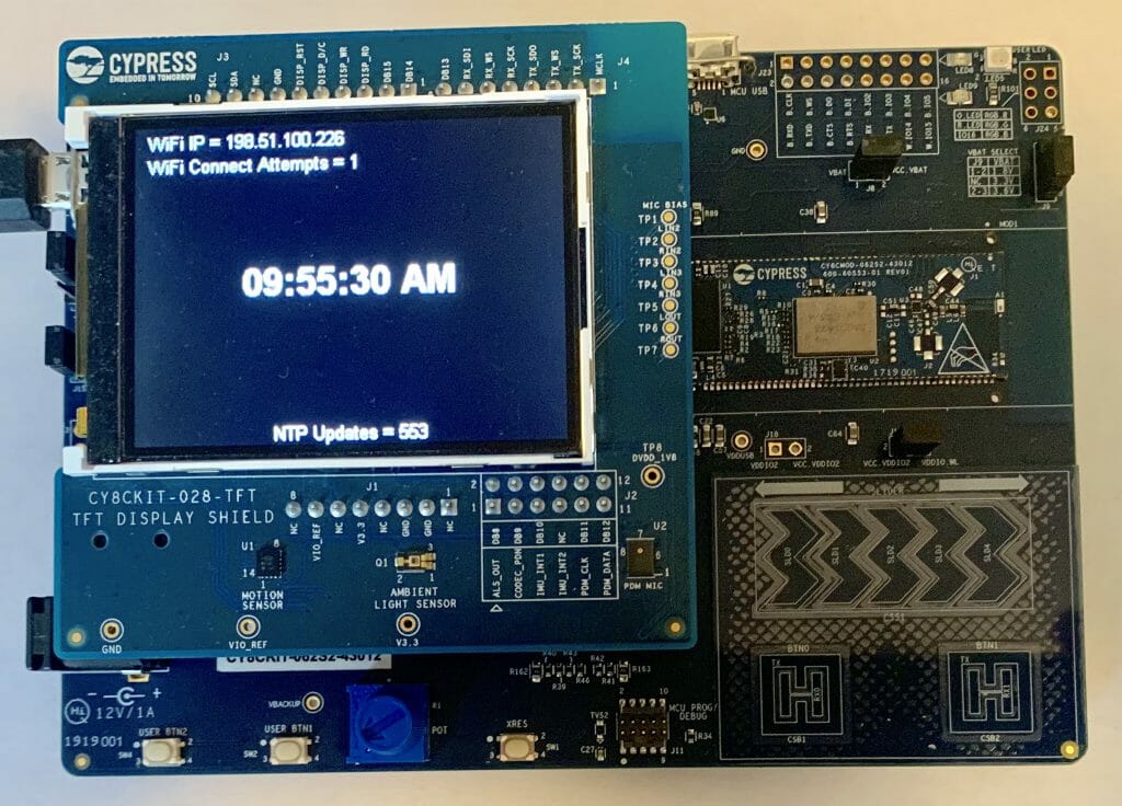
For this article I will discuss:

  1. MBED OS Project Setup
  2. MBED OS Event Queues
  3. The RTOS Architecture
  4. The Display Function(s)
  5. The NTP Thread
  6. The WiFI/Main Thread
  7. The Whole Program

Project Setup: Create and Configure Project + Add the Libraries

You should start this project by creating a project by running “mbed new NTPDemo” or by using mbed studio to create a new project.  To run this project requires at least mbed-os-5.13.3.  You have two basic choices to get the latest mbed.  For some reason which I don’t totally understand when you run mbed new it gives you a slightly older version of mbed-os.  To get a new version you can either “cd mbed-os ; mbed update mbed-os-5.13.3” or to get the latest “cd mbed-os ; mbed update master”.

In this project I use three libraries, emWin, the IoT Expert ST7789V library (for the display) and the ntp-client library.  To add them run

The emWin library requires that you tell emWin about which version of the library .a to link with.  You can do this by adding this to the mbed_app.json

{
    "target_overrides": {
        "*": {
            "target.components_add": ["EMWIN_OSNTS"]
        }
    }
}

MBED OS Event Queues

For this project I will use one of the cool RTOS mechanisms that is built into MBED OS,  the “EventQueue“.   There is a nice tutorial in the MBED OS documentation.  An EventQueue is a tool for running a function “later” and in a different thread context.  What does that mean?  It means that there is a thread that sits around waiting until you tell it to run a function.  You tell it to run the function by pushing a function pointer into it’s EventQueue.  In other words, an EventQueue is a thread that waits for functions to be pushed into queue.  When the function is pushed into the queue it runs it.

How is this helpful?  There are a several of reasons.

  • If you are in an ISR it allows you to defer execution of something to the main program.
  • It can be used to serialize access to some resource – in my case the display.
  • It allows you to schedule some event to happen regularly

When MBED OS starts it automatically creates two of these event queues one of the queue threads runs at “osPriorityNormal” and can be accessed via mbed_event_queue();  The other event queue runs at “osPriorityHigh” and can be accesed by mbed_highprio_event_queue();  For some reason (which I don’t understand) these queues are documented on a separate page.

The RTOS Architecture

Here is a picture of the architecture of my program.


The Main Thread

The main function which is also the main thread, which then becomes the WiFi Thread

  1. Initializes the GUI
  2. Starts up the Display Event Queue
  3. Turns on the WiFi and attaches a callback (to notify the program of WiFI Status Changes)
  4. Try’s to connect to the WiFi Network
  5. If it fails, it updates the display and try’s again after 2 seconds
  6. Once it is connected it starts up the NTP Server Thread
  7. And then waits for the WiFi semaphore to be set… which only happens if WiFi gets disconnected at which point it goes back to the start of the WiFI connection and try again.
int main()
{
    int wifiConnectionAttempts;
    int ret;

    GUI_Init();
    displayQueue = mbed_event_queue();
    displayQueue->call_every(1000, &updateDisplayTime);

    wifi = WiFiInterface::get_default_instance();
    wifi->attach(&wifiStatusCallback);

   while(1)
   {
       wifiConnectionAttempts = 1;
        do {

            ret = wifi->connect(MBED_CONF_APP_WIFI_SSID, MBED_CONF_APP_WIFI_PASSWORD, NSAPI_SECURITY_WPA_WPA2);
            displayQueue->call(updateDisplayWiFiConnectAttempts,wifiConnectionAttempts);

            if (ret != 0) {
                wifiConnectionAttempts += 1;
                wait(2.0); // If for some reason it doesnt work wait 2s and try again
            }
        } while(ret !=0);

        // If the NTPThread is not running... then start it up
        if(netTimeThreadHandle.get_state() == Thread::Deleted)
            netTimeThreadHandle.start(NTPTimeThread);
 
        WiFiSemaphore.acquire();
   }

Display Event Queue

Display EventQueue is used to run functions which update the display.  By using an EventQueue it ensure that the Display updates happen serially and there are no display resource conflicts.  The four functions are

  1. updateDisplayWiFiStatus
  2. updateDisplayWifiConnectAttempts
  3. updateDisplayNTPCount
  4. updateDisplayTime

I wanted a function which could display the state of the WiFi connection on the screen.  This is a string of text which is generated in the connection status function.  In order to send the message, the connection status function will “malloc” which then requires the updateDisplayWiFiStatus function to free the memory associated with the message.

#define DISP_LEFTMARGIN 10
#define DISP_TOPMARGIN 4
#define DISP_LINESPACE 2
// updateDisplayWiFiStatus
// Used to display the wifi status
void updateDisplayWiFiStatus(char *status)
{
    GUI_SetFont(GUI_FONT_16_1);
    GUI_DispStringAt(status,DISP_LEFTMARGIN, DISP_TOPMARGIN); 
    free(status);  
}

When I started working on this program I had a bug in my connections so I added the ability to tell how many WiFI connections attempts had happened.  I also wondered how many times there might be a disconnect if I ran this program a long time.  The answer is I ran it for two days and it didn’t disconnect a single time.  This function simply takes a number from the caller and displays it on the screen.  Notice that I use snprintf to make sure that I don’t overrun the buffer (which I doubt could happen because I made it 128 bytes).

// updateDisplayWiFiConnectAttempts
// This function displays the number of attempted connections
void updateDisplayWiFiConnectAttempts(int count)
{
    char buffer[128];
    snprintf(buffer,sizeof(buffer),"WiFi Connect Attempts = %d",count); 
    GUI_SetFont(GUI_FONT_16_1);
    GUI_DispStringAt(buffer,DISP_LEFTMARGIN, DISP_TOPMARGIN + (GUI_GetFontSizeY()+DISP_LINESPACE) ); 
}

I was curious how many times the NTP connection would happen.  So I added the ability to display a count.  Notice that I use a static variable to keep track of the number of times this function is called rather than pushing the number as an argument.  Perhaps this is a design flaw?

// updateDisplayNTPCount
// updates the display with the number of time the NTP Server has been called
void updateDisplayNTPCount(void)
{
    static int count=0;
    char buffer[128];
    count = count + 1;
    snprintf(buffer,sizeof(buffer),"NTP Updates = %d\n",count);
    GUI_SetFont(GUI_FONT_16_1);
    GUI_DispStringHCenterAt(buffer,LCD_GetXSize()/2,LCD_GetYSize() - GUI_GetFontSizeY()); // near the bottom
}

The main display function is the seconds which is displayed in the middle of the screen.  I get the time from the RTC in the PSoC and is set by the NTP Server.  Notice my rather serious hack to handle the Eastern time difference to UTC… which unfortunately only works in the Summer.

// updateDisplayTime
// This function updates the time on the screen
void updateDisplayTime()
{
  time_t rawtime;
  struct tm * timeinfo;
  char buffer [128];

  time (&rawtime);
  rawtime = rawtime - (4*60*60); // UTC - 4hours ... serious hack which only works in summer

  timeinfo = localtime (&rawtime);
  strftime (buffer,sizeof(buffer),"%r",timeinfo);
  GUI_SetFont(GUI_FONT_32B_1);
  GUI_DispStringHCenterAt(buffer,LCD_GetXSize()/2,LCD_GetYSize()/2 - GUI_GetFontSizeY()/2);
}

NTP Time Thread

The Network Time Protocol was invented in 1981 by Dr. David Mills for use in getting Internet connected computers to have the right time.  Since then it has been expanded a bunch of times to include Cellular, GPS and other networks.  The scheme includes methods for dealing with propogation delay etc.  However, for our purposes we will just ask one of the NIST computers, what time is it?

The way it works is that you setup a structure with 48 bytes in it.  Then you open a UDP connection to an NTP server (which NIST runs for you) then it will fill out the same structure with some time data and send it back to you.  Here is the packet:

typedef struct
{

  uint8_t li_vn_mode;      // Eight bits. li, vn, and mode.
                           // li.   Two bits.   Leap indicator.
                           // vn.   Three bits. Version number of the protocol.
                           // mode. Three bits. Client will pick mode 3 for client.

  uint8_t stratum;         // Eight bits. Stratum level of the local clock.
  uint8_t poll;            // Eight bits. Maximum interval between successive messages.
  uint8_t precision;       // Eight bits. Precision of the local clock.

  uint32_t rootDelay;      // 32 bits. Total round trip delay time.
  uint32_t rootDispersion; // 32 bits. Max error aloud from primary clock source.
  uint32_t refId;          // 32 bits. Reference clock identifier.

  uint32_t refTm_s;        // 32 bits. Reference time-stamp seconds.
  uint32_t refTm_f;        // 32 bits. Reference time-stamp fraction of a second.

  uint32_t origTm_s;       // 32 bits. Originate time-stamp seconds.
  uint32_t origTm_f;       // 32 bits. Originate time-stamp fraction of a second.

  uint32_t rxTm_s;         // 32 bits. Received time-stamp seconds.
  uint32_t rxTm_f;         // 32 bits. Received time-stamp fraction of a second.

  uint32_t txTm_s;         // 32 bits and the most important field the client cares about. Transmit time-stamp seconds.
  uint32_t txTm_f;         // 32 bits. Transmit time-stamp fraction of a second.

} __PACKED ntp_packet_t;              // Total: 384 bits or 48 bytes.

The code to send the packet is really simple.  The only trick is that when you send data on the network you almost always use big endian, so you need to use the function nthol to convert.

void NTPClient::set_server(char* server, int port) {
    nist_server_address = server;
    nist_server_port = port;
}

time_t NTPClient::get_timestamp(int timeout) {
    const time_t TIME1970 = (time_t)2208988800UL;
    int ntp_send_values[12] = {0};
    int ntp_recv_values[12] = {0};

    SocketAddress nist;

    if (iface) {
        int ret_gethostbyname = iface->gethostbyname(nist_server_address, &nist);

        if (ret_gethostbyname < 0) {
            // Network error on DNS lookup
            return ret_gethostbyname;
        }

        nist.set_port(nist_server_port);

        memset(ntp_send_values, 0x00, sizeof(ntp_send_values));
        ntp_send_values[0] = '\x1b';

        memset(ntp_recv_values, 0x00, sizeof(ntp_recv_values));

        UDPSocket sock;
        sock.open(iface);
        sock.set_timeout(timeout);

        sock.sendto(nist, (void*)ntp_send_values, sizeof(ntp_send_values));

        SocketAddress source;
        const int n = sock.recvfrom(&source, (void*)ntp_recv_values, sizeof(ntp_recv_values));

        if (n > 10) {
            return ntohl(ntp_recv_values[10]) - TIME1970;

The times in the structure are represented with two 32-bit numbers

  • # of seconds since 1/1/1900 (notice this is not 1970)
  • # of fractional seconds in 1/2^32 chunks (that ain’t a whole lotta time)

The four numbers are

  • Reference Time – when you last sent a packet
  • Origin Time – when you sent the packet (from your clock)
  • Receive Time – when the NTP server received your packet
  • Transmit Time – when your NTP server sent the packet back to you

You know when you send the packet – called T1.  You know when you received the packet – called T4.  You know when the other side received your packet – called T2 and you know when the other side sent the packet called T3.  With this information you can calculate the network delay, stability of the clocks etc.  However, the simplest thing to do is to take the transit time, which is in UTC, and set your clock assuming 0 delay.

In MBEDOS to set the RTC clock in the PSoC you call the function with the number of seconds since 1/1/1970.  Don’t forget that the time that comes back from NTP is in seconds since 1/1/1900.

                set_time(timestamp);

Given that the PSoC 6 RTC counts in seconds you can just ignore the partial seconds.

WiFi Semaphore

At the top of main I registered to WiFi that I want a callback when the state of the WiFi changes.

    wifi->attach(&wifiStatusCallback);

This function does two things.

  • Updates the screen as the state goes from unconnected to connected
  • Unlocks a semaphore to tell the main thread to reconnect.
// wifiStatusCallback
// Changes the display when the wifi status is changed
void wifiStatusCallback(nsapi_event_t status, intptr_t param)
{
    const int buffSize=40;
    char *statusText;
    statusText = (char *)malloc(buffSize);

    switch(param) {
        case NSAPI_STATUS_LOCAL_UP:
            snprintf(statusText,buffSize,"WiFi IP = %s",wifi->get_ip_address());
            break;
        case NSAPI_STATUS_GLOBAL_UP:
            snprintf(statusText,buffSize,"WiFi IP = %s",wifi->get_ip_address());
            break;
        case NSAPI_STATUS_DISCONNECTED:
            WiFiSemaphore.release();
            snprintf(statusText,buffSize,"WiFi Disconnected");
            break;
        case NSAPI_STATUS_CONNECTING:
            snprintf(statusText,buffSize,"WiFi Connecting");
            break;
        default:
            snprintf(statusText,buffSize,"Not Supported");
            break;
    }
    displayQueue->call(updateDisplayWiFiStatus,statusText);
}

The Whole Program

Here is the whole program.

#include "mbed.h"
#include "GUI.h"
#include "mbed_events.h"
#include "ntp-client/NTPClient.h"

Thread netTimeThreadHandle;

WiFiInterface *wifi;
EventQueue *displayQueue;
Semaphore WiFiSemaphore;

/******************************************************************************************
*
* Display Functions
*
********************************************************************************************/

#define DISP_LEFTMARGIN 10
#define DISP_TOPMARGIN 4
#define DISP_LINESPACE 2
// updateDisplayWiFiStatus
// Used to display the wifi status
void updateDisplayWiFiStatus(char *status)
{
    GUI_SetFont(GUI_FONT_16_1);
    GUI_DispStringAt(status,DISP_LEFTMARGIN, DISP_TOPMARGIN); 
    free(status);  
}

// updateDisplayWiFiConnectAttempts
// This function displays the number of attempted connections
void updateDisplayWiFiConnectAttempts(int count)
{
    char buffer[128];
    snprintf(buffer,sizeof(buffer),"WiFi Connect Attempts = %d",count); 
    GUI_SetFont(GUI_FONT_16_1);
    GUI_DispStringAt(buffer,DISP_LEFTMARGIN, DISP_TOPMARGIN + (GUI_GetFontSizeY()+DISP_LINESPACE) ); 
}

// updateDisplayNTPCount
// updates the display with the number of time the NTP Server has been called
void updateDisplayNTPCount(void)
{
    static int count=0;
    char buffer[128];
    count = count + 1;
    snprintf(buffer,sizeof(buffer),"NTP Updates = %d\n",count);
    GUI_SetFont(GUI_FONT_16_1);
    GUI_DispStringHCenterAt(buffer,LCD_GetXSize()/2,LCD_GetYSize() - GUI_GetFontSizeY()); // near the bottom
}

// updateDisplayTime
// This function updates the time on the screen
void updateDisplayTime()
{
  time_t rawtime;
  struct tm * timeinfo;
  char buffer [128];

  time (&rawtime);
  rawtime = rawtime - (4*60*60); // UTC - 4hours ... serious hack which only works in summer

  timeinfo = localtime (&rawtime);
  strftime (buffer,sizeof(buffer),"%r",timeinfo);
  GUI_SetFont(GUI_FONT_32B_1);
  GUI_DispStringHCenterAt(buffer,LCD_GetXSize()/2,LCD_GetYSize()/2 - GUI_GetFontSizeY()/2);
}

/******************************************************************************************
* NTPTimeThread
* This thread calls the NTP Timeserver to get the UTC time
* It then updates the time in the RTC
* And it updates the display by adding an event to the display queue
********************************************************************************************/
void NTPTimeThread()
{
    NTPClient ntpclient(wifi);

    while(1)
    {
        if(wifi->get_connection_status() == NSAPI_STATUS_GLOBAL_UP)
        {
            time_t timestamp = ntpclient.get_timestamp();
            if (timestamp < 0) {
                // probably need to do something different here
            } 
            else 
            {
                set_time(timestamp);
                displayQueue->call(updateDisplayNTPCount);
            }
        }
        wait(60.0*5); // Goto the NTP server every 5 minutes
    }
}

/******************************************************************************************
*
* Main & WiFi Thread
*
********************************************************************************************/

// wifiStatusCallback
// Changes the display when the wifi status is changed
void wifiStatusCallback(nsapi_event_t status, intptr_t param)
{
    const int buffSize=40;
    char *statusText;
    statusText = (char *)malloc(buffSize);

    switch(param) {
        case NSAPI_STATUS_LOCAL_UP:
            snprintf(statusText,buffSize,"WiFi IP = %s",wifi->get_ip_address());
            break;
        case NSAPI_STATUS_GLOBAL_UP:
            snprintf(statusText,buffSize,"WiFi IP = %s",wifi->get_ip_address());
            break;
        case NSAPI_STATUS_DISCONNECTED:
            WiFiSemaphore.release();
            snprintf(statusText,buffSize,"WiFi Disconnected");
            break;
        case NSAPI_STATUS_CONNECTING:
            snprintf(statusText,buffSize,"WiFi Connecting");
            break;
        default:
            snprintf(statusText,buffSize,"Not Supported");
            break;
    }
    displayQueue->call(updateDisplayWiFiStatus,statusText);
}


int main()
{
    int wifiConnectionAttempts;
    int ret;

    GUI_Init();
    displayQueue = mbed_event_queue();
    displayQueue->call_every(1000, &updateDisplayTime);

    wifi = WiFiInterface::get_default_instance();
    wifi->attach(&wifiStatusCallback);

   while(1)
   {
       wifiConnectionAttempts = 1;
        do {

            ret = wifi->connect(MBED_CONF_APP_WIFI_SSID, MBED_CONF_APP_WIFI_PASSWORD, NSAPI_SECURITY_WPA_WPA2);
            displayQueue->call(updateDisplayWiFiConnectAttempts,wifiConnectionAttempts);

            if (ret != 0) {
                wifiConnectionAttempts += 1;
                wait(2.0); // If for some reason it doesnt work wait 2s and try again
            }
        } while(ret !=0);

        // If the NTPThread is not running... then start it up
        if(netTimeThreadHandle.get_state() == Thread::Deleted)
            netTimeThreadHandle.start(NTPTimeThread);
 
        WiFiSemaphore.acquire();
   }
}


MBEDOS Libraries & emWin Configuration Files

Summary

I have written a fair amount about Graphics Displays, using the Segger emWin graphics library and MBED OS.  I have found it irritating to do all of the configuration stuff required to get these kinds of projects going.  I inevitably go back, look at my old articles, find the github repository of my example projects etc.  This week I wanted to write some programs for the new CY8CKIT-062S2-43012 development kit so I thought that I would try all of the Cypress displays using that development kit.  Rather than starting with example projects, this time I decided to build configurable mbedos libraries. In this article I will show you how to build configurable mbed os libraries which will allow you to use the emWin Graphics Library with all of the Cypress display shields.

In this article I will walk you through:

  • The CY8CKIT-032 & SSD1306 Display Driver & emWin
  • MBED OS Libraries
  • MBED OS Configuration
  • Configuration Overrides
  • The SSD1306 emWin Configuration
  • Using the SSD1306 Configuration Library
  • emWin Configuration Libraries

The CY8CKIT-032 & SSD1306 Display Driver & emWin

The CY8CKIT-032 has a little 0.96″ OLED display that is attached to the Salomon Systech SSD1306 Display Driver.  I have written quite a bit about this little screen as it is cheap and fairly easy to use.  It became even easier when we released the Segger emWin SPAGE display driver.  And with my new library it should be trivial to use and configure for your setup.

You can read in detail about the functionality here but in short:

  • The display driver chip is attached to the PSoC via I2C
  • You need to provide the Segger emWin driver
    • GUIConfig.h/cpp – Segger GUI configuration
    • LCDConf.h/cpp – Setup files for the LCD
    • GUI_X_Mbed.cpp – RTOS control functions for delays etc.
    • ssd1306.h/c – physical interface to the SSD1306 controller
  • You need to initialize the PSoC I2C before talking to the display
  • You need to initialize the display driver chip before drawing on the screen

In general all of this configuration will be the same from project to project to project.  However, you may very will find that you have the display connected to a different set of pins.  I suppose that would put all of these files into some directory.  Then you could copy that directory into your project every time.  Which would leave you with modifying the configuration to meet your specific board connection.  The problem with that is you have now deeply intertwined your project with those files.

MBED OS has given us a really cool alternative.  Specifically the Library and configuration systems.

MBED OS Libraries

An MBED OS library is simply a git repository.  Just a directory of source files.  When you run the command “mbed add repository” it does two basic things

  1. It does a “git clone” to make a copy of the repository inside of your project.
  2. It creates a file with the repository name.lib which contains the URL to the version of the repository

Here is a an MBED add of my graphics configuration library for the SSD1306

(mbed CLI) ~/Mbed Programs/test032 $ mbed add git@github.com:iotexpert/mbed-os-emwin-ssd1306.git
[mbed] Working path "/Users/arh/Mbed Programs/test032" (program)
[mbed] Adding library "mbed-os-emwin-ssd1306" from "ssh://git@github.com/iotexpert/mbed-os-emwin-ssd1306" at latest revision in the current branch
[mbed] Updating reference "mbed-os-emwin-ssd1306" -> "https://github.com/iotexpert/mbed-os-emwin-ssd1306/#7986006c17bd572da317257640f35ec3b232414e"
(mbed CLI) ~/Mbed Programs/test032 $ ls mbed-os-emwin-ssd1306
GUIConf.cpp    GUI_X_Mbed.cpp LCDConf.h      mbed_lib.json  ssd1306.h
GUIConf.h      LCDConf.cpp    README.md      ssd1306.cpp
(mbed CLI) ~/Mbed Programs/test032 $ more mbed-os-emwin-ssd1306.lib 
https://github.com/iotexpert/mbed-os-emwin-ssd1306/#7986006c17bd572da317257640f35ec3b232414e
(mbed CLI) ~/Mbed Programs/test032 $ 

Notice that when I “ls’d” the directory that all of file required to confiugure emWin for the SSD1306 became part of my project.  And the file mbed-os-emwin-ssd1306.lib was created with the URL of the github repository.

https://github.com/iotexpert/mbed-os-emwin-ssd1306/#7986006c17bd572da317257640f35ec3b232414e

When you run “mbed compile” the build system just searches that directory for cpp and h files turns them into .0’s and add them to the the BUILD directory.  However, before it compiles it run the configuration system.

MBED OS Configuration System

The configuration system takes the file “mbed_lib.json” parses it and turns it into a C-header file called mbed_config.h.  The format of this file is

  • The name of the component – in this case “SSD1306_OLED”
  • The parameters of the component SDA, SCL, I2CADDRESS and I2CFREQ
{
    "name" : "SSD1306_OLED",
    "config": {
        "SDA":"P6_1",
        "SCL":"P6_0",
        "I2CADDRESS":"0x78",
        "I2CFREQ":"400000"
    }
}

This header file is then placed into the BUILD directory of your project and is included as part of #include “mbed.h”

If you open mbed_config.h you will find that it creates #defines of the component parameters

#define MBED_CONF_SSD1306_OLED_I2CADDRESS                                     0x78                                                                                             // set by library:SSD1306_OLED
#define MBED_CONF_SSD1306_OLED_I2CFREQ                                        400000                                                                                           // set by library:SSD1306_OLED
#define MBED_CONF_SSD1306_OLED_SCL                                            P6_0                                                                                             // set by library:SSD1306_OLED
#define MBED_CONF_SSD1306_OLED_SDA                                            P6_1

This is really nice because I can then reference those #defines in my source code.

Configuration Overrides

When you are building the library you can create an arbitrary number of these parameters which are then applied to all of the uses of that library.  Or if there is some reason why one target is different you can specify the parameters for that specific target by changing the mbed_lib.json.  For instance if the CY8CKIT_062S2_43012 need a 100K I2C frequency instead of 400K (it doesn’t), you could do this:

{
    "name" : "SSD1306_OLED",
    "config": {
        "SDA":"P6_1",
        "SCL":"P6_0",
        "I2CADDRESS":"0x78",
        "I2CFREQ":"400000"
    },
    "target_overrides" : {
        "CY8CKIT_062S2_43012" : {
            "I2CFREQ":"100000"
        }
    }
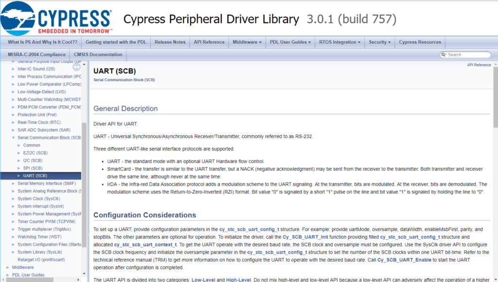
}

The application developer is also allowed to over-ride the parameter by providing the target overrides in the MBED OS file “mbed_app.json”.  Notice that the way you specify the parameter name is different in this file than the mbed_lib.json.  In this case you give it the name of the library.parametername.  Here is an example setting the I2CFrequency to 100K

{
	"target_overrides": {
        "*": {
            "target.components_add": ["EMWIN_OSNTS"]
        },
        "CY8CKIT_062S2_43012" : {
            "SSD1306_OLED.I2CFREQ": "1000000"
        }
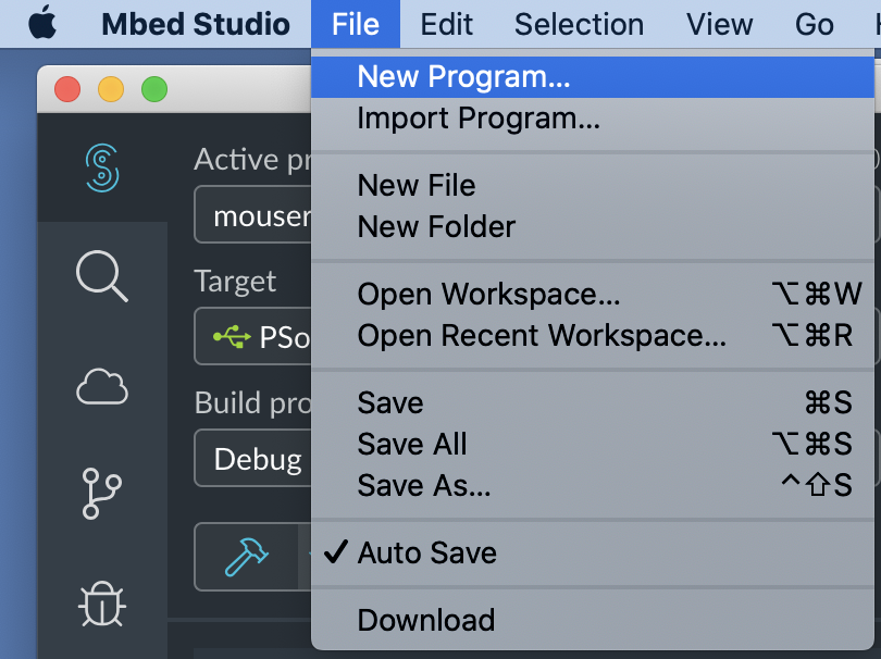
	}
}

Which would result in a change to the generated #define in mbed_config.h

#define MBED_CONF_SSD1306_OLED_I2CFREQ                                        1000000

Notice that you can specify a “*” to match all of the targets, or you can specify the exact target.

The SSD1306 emWin Configuration

I use the configuration system to generate #defines for the

  • SCL/SDA Pin Numbers
  • I2C Address
  • I2C Frequency

Which lets my use those #defines in ssd1306.cpp

I2C Display_I2C(MBED_CONF_SSD1306_OLED_SDA, MBED_CONF_SSD1306_OLED_SCL);

And

void ssd1306_Init(void) 
{
    Display_I2C.frequency(MBED_CONF_SSD1306_OLED_I2CFREQ);
}
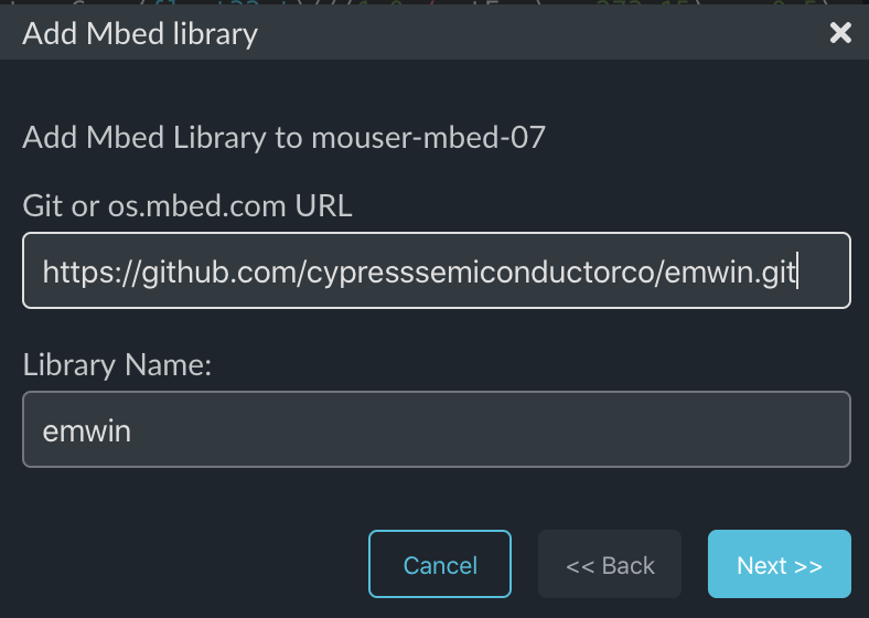
Using the SSD1306 Configuration Library

Lets make an example project that uses the CY8CKIT_062S2_43012 and the CY8CKIT032 using the Segger graphics library and my configuration library.

Start by make a new project, adding the emWin library and the configuration library.  It should look something like this

Now edit the mbed_app.json to add the emWin library

{
	"target_overrides": {
        "*": {
            "target.components_add": ["EMWIN_OSNTS"]
        }
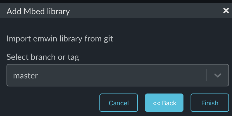
	}
}

Create the main.cpp which simply initializes the display and displays “hello world”

#include "mbed.h"
#include "GUI.h"

int main()
{
  GUI_Init();
  GUI_SetColor(GUI_WHITE);
  GUI_SetBkColor(GUI_BLACK);
  GUI_SetFont(GUI_FONT_13B_1);
  GUI_SetTextAlign(GUI_TA_CENTER);
  GUI_DispStringAt("Hello World", GUI_GetScreenSizeX()/2,GUI_GetScreenSizeY()/2 - GUI_GetFontSizeY()/2);
}

When you compile it with

  • mbed compile -t GCC_ARM -m CY8CKIT_062S2_43012 -f

You should get something like this:

And your screen should look like this (notice I made the font bigger than the original screen shot)

emWin Configuration Libraries

Finally I created libraries for all of the Cypress displays.  You can use these to make your project easier to get going.