In the previous four posts I talked about building an IOT device using the new CY8CKIT145. You might remember from the first post that my original objective in picking up the board was to try a new feature of PSoC Creator. Well, over the last few days I have been trying out that feature. Actually, it isn’t a feature of the software, it is a feature of some of the new chips called the Smart IO. The Smart IO is a programmable logic bock that sits between the High Speed IO Matrix (HSIOM) of the chip and the Input/Output Port. The HSIOM has all of the peripherals (SCB, TCPWM etc) of the chips attached to it. The Smart IO will allow you to take signals from inside or outside of the chip, perform logic functions on them, and then drive those signals into or out of the chip. Some of examples of why you might want to do this include:
- Combining several inputs (from the outside) to trigger an interrupt
- Inverting a signal entering the chip
- Inverting a signal exiting the chip
- Remapping an input from one pin to a different input (e.g. flipping Tx, Rx pins)
- Buffering one signal into multiple output pins (to increase the drive strength)
As usual with Cypress programmable logic, you can do a jaw dropping number of clever things. This block includes sequential logic as well as combinational logic, so it is possible to make state machines in the fabric. It also includes more surprises which have not been shown yet.
The Smart IO works the same as other peripheral blocks, you start by dragging the component onto the schematic and double clicking to start the customizer.
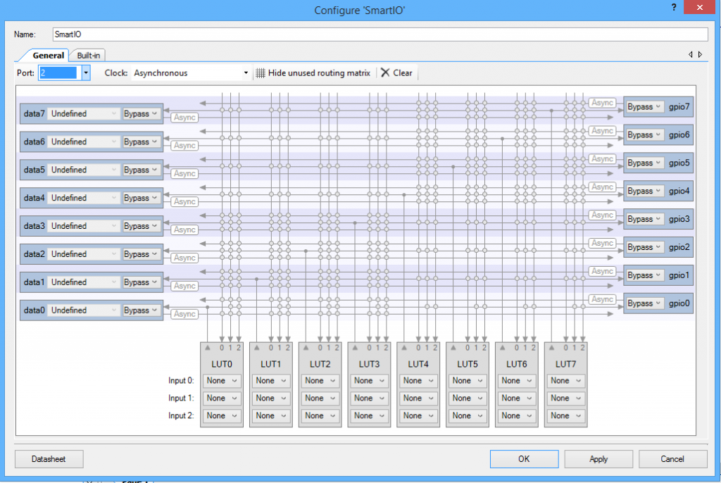
When you start the customizer you get the screen below. The first thing to decide is which Port is going to use the Smart IO. The Smart IO completely takes over an entire port. On this chip there are two Smart IOs, one on Port 2 and one on Port 3. When you look at the customizer there are some things to notice:
- On the right side of the customizer you can see the 8 GPIO pins. The dropdown menus that are currently labeled “Bypass” allow you to select the mode of the pin (Bypass, Input, Output, None).
- On the bottom of the customizer you can see the 8 LUTs and select their inputs.
- On the left side of the customizer you can see the the 8 connections to/from the HSIOM. The drop down menu that is currently labeled “Bypass” allows you to select the mode of that connection to the HSIOM (Bypass, Input, Output, None). I will talk about the “Undefined” menu in the with the next picture
- In the middle of the customizer is the routing matrix. Horizontally on the routing matrix there are 8 groups of three wires. The top wire in each group is a wire that originates with the GPIO. The middle wire originates from the corresponding LUT. The bottom wire originates from the HSIOM. For example the top three wires in the picture are
- Line 1: from GPIO7
- Line 2: from LUT 7
- Line 3: from Data7
- You can “make” the connection by either by clicking the solder dot or by choosing from the coresponding drop down menu (more on that below)
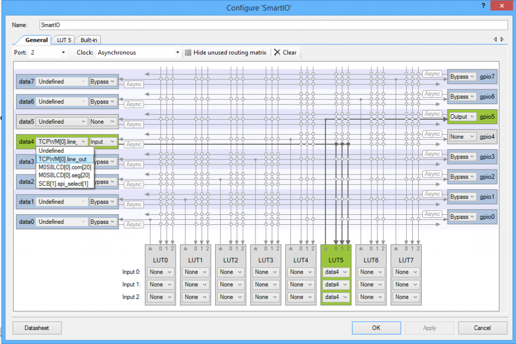
The other menu on the HSIOM side of the customizer says “Undefined”. This menu has a list of each fixed function device and the inputs/outputs of that device that can be connected to that input/output. This menu doesn’t actually change anything in your design, it is only for information. For example you can see in the screen shot below that data4 can connect to:
- TCPWM0: Line_Out
- LCD0: COM[20]
- LCD0: SEG[20]
- SCB1: Spi Select[1]
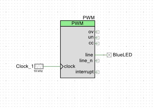
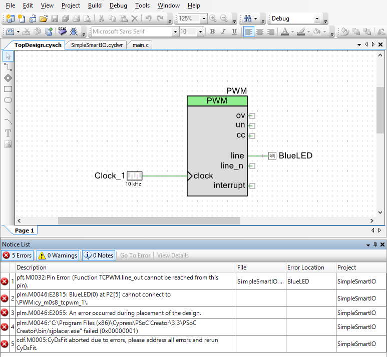
The best way to show you how all this works is with an example. One of the frustrating things for me in the PSoC 4 Family has always been that the fixed function blocks (TCPWM, SCB) are only allowed to connect to a few pins on the chip. This can be a bit of a pain if you have a board that is already wired and you need to remap a pin. Take for example, on the Cy8CKIT-145 the user LED on the main board is connected to P2[5]. If I want to drive that LED with the Line out (instead of the Line_Out_N) I would create a schematic like this:
When I go to the DWR to assign the pins I would see that the BlueLED cannot be attached to P2[5]. You can see all of the legal placements of that pin because they are highlighted in green.
If I try to do it anyway, I will get the following error when I build.
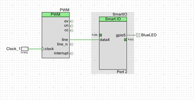
This error says that I cannot connect the “line” output of the TCPWM to P2[5] (the pin with the LED). That sucks. But, with the Smart IO, I can “remap” the TCPWM Line output to P2[5]. To do this, I will start with a by adding a SmartIO to my schematic and configuring it.
- Select Port 2
- Configure GPIO 5 to “Output”. This can be done by either clicking on the “solder dot” or by selecting output from the drop down menu
- Select data 4 as “Input”
- Select data 4 as “TCPWM[0].line. Remember that this is ONLY for your information and doesn’t actually change anything in the project.
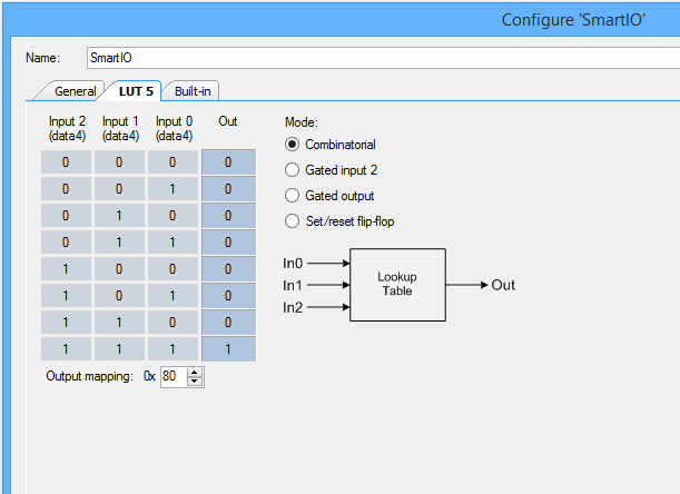
- Select the 3 inputs to LUT5 to be the data4 line which can be done from the three drop down menus or by clicking the three corresponding solder dots.
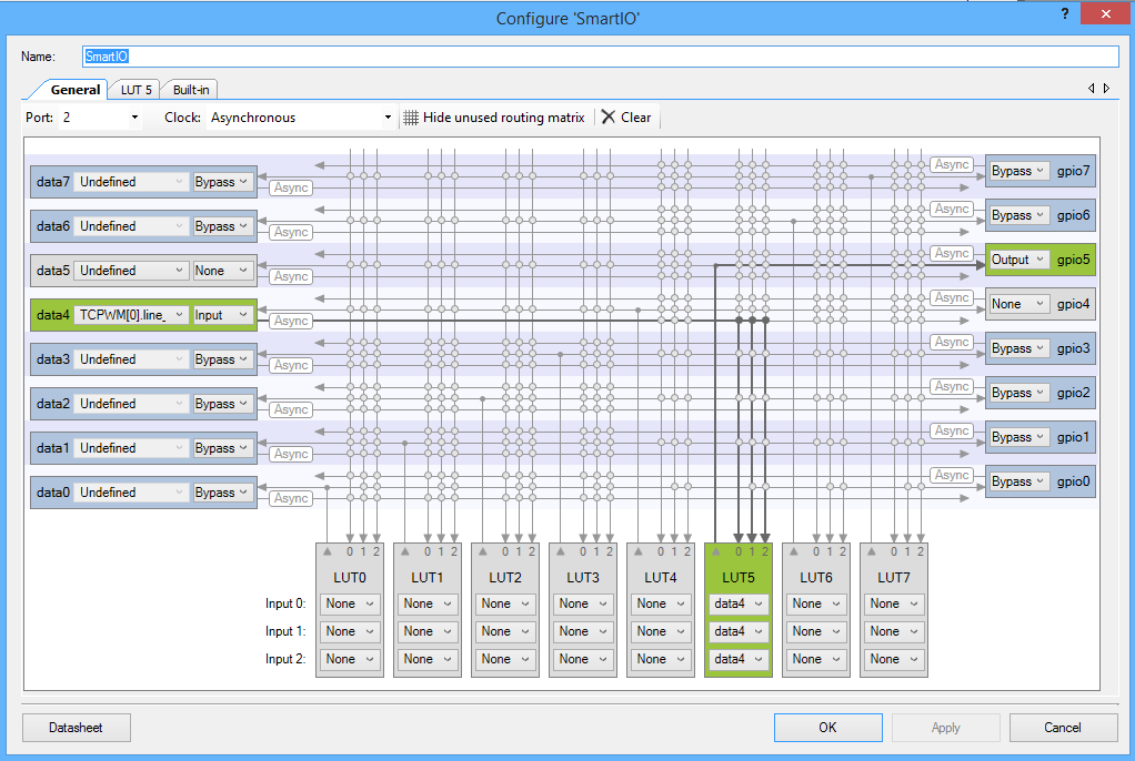 Next, I configure the LUT to “passthrough” by setting up 000 = 0 and 111=1 (which are the only two possible combinations as the three inputs are tied together). You change the “Out”s from 0->1 and 1->0 by clicking on it.
Then I will re-wire up the schematic to look like this:
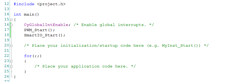
The firmware is trivial, just start the PWM and the SmartIO
When I program the kit the blue LED starts blinking. Cool.
In the next posts I will teach you how to use some other configurations of the Smart IO and how to use the CapSense block to create inputs for the Smart IO.
You can find this PSoC Creator workspace on github in the directory called “SmartIO”. This project is called “SimpleSmartIO”.
Index
Description
PSoC4000s & The SmartIO – Part 1
An introduction to the SmartIO and first project
PSoC4000s & CSX Mutual CapSense Buttons Part 1
Using mutual capacitance
PSoC4000s & CSX Mutual CapSense Buttons Part 2
Using the CapSense tuner
PSoC4000s & The SmartIO – Part 2
A 3 input XOR logic gate
PSoC4000s & The SmartIO – Part 3
A 3 bit up counter state machine
PSoC4000s & The SmartIO – Part 4
Using an external clock with the Smart IO
PSoC4000s & The SmartIO – Part 5
Triggering an interrupt

1 Comment
Thank you Alan! Your post help me tremendously.