Summary
In the previous PSoC FreeRTOS article I showed you a scheme for sharing the I2C between multiple tasks by sending “I2C Transactions” to a single I2C Master thread. In this article I will modify the Accelerometer task to use the hardware interrupt pin from the KXTJ2-1009 to only read data when there is new data to be read (i.e. stop polling). I will also modify the project to use “kxtj2.h” a header file which I downloaded from Rohm’s website with all of the register definitions.
Updates to the PSoC FreeRTOS Project Schematics
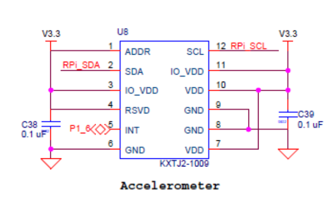
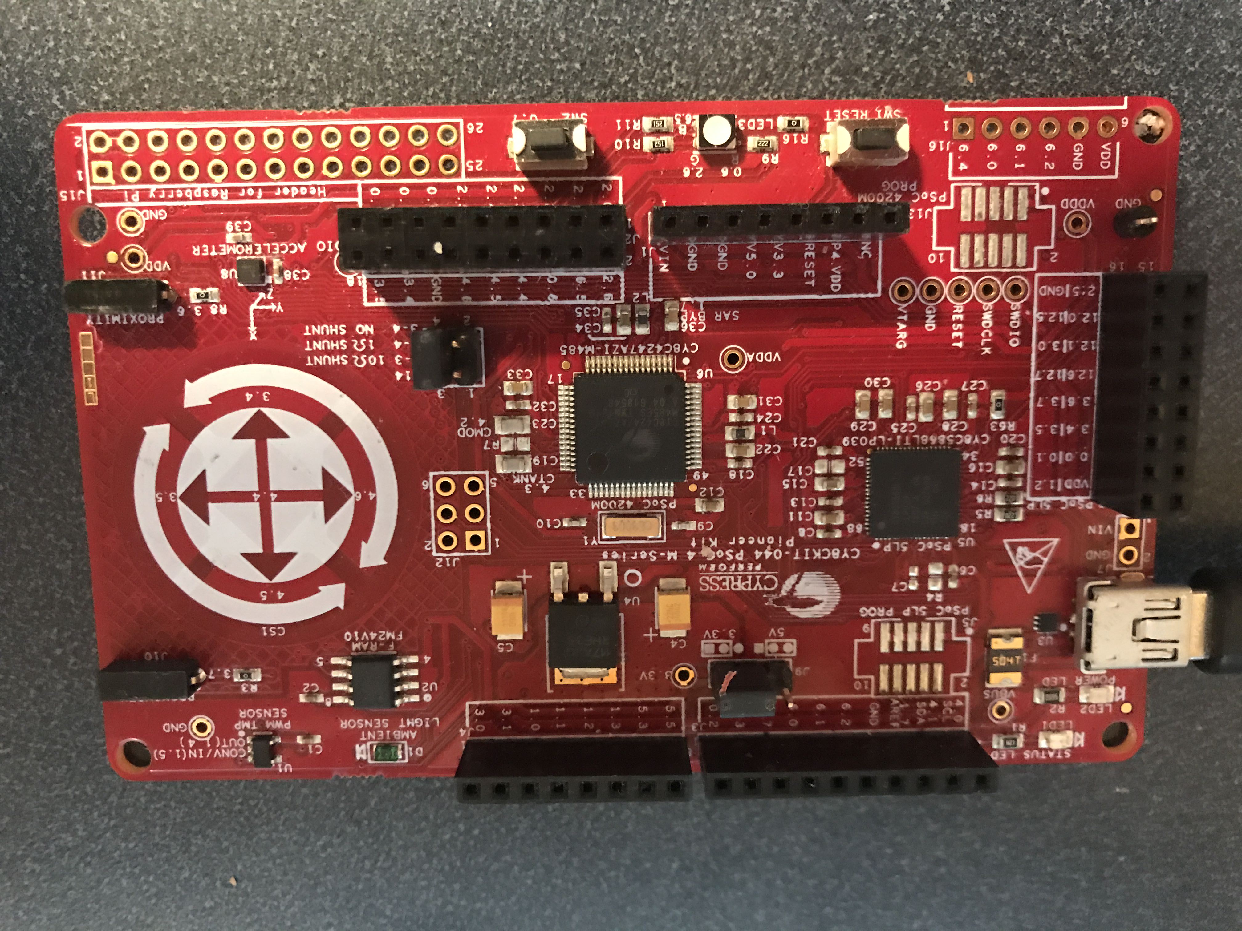
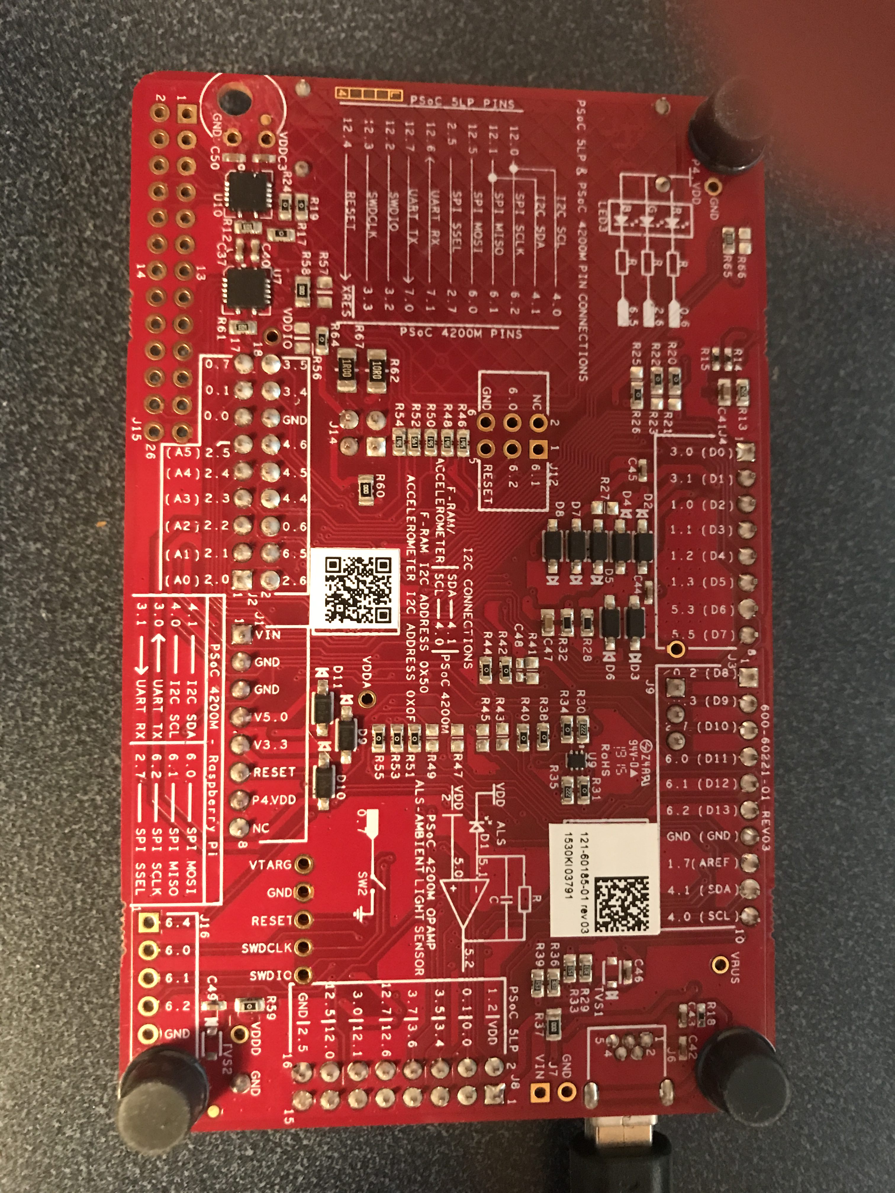
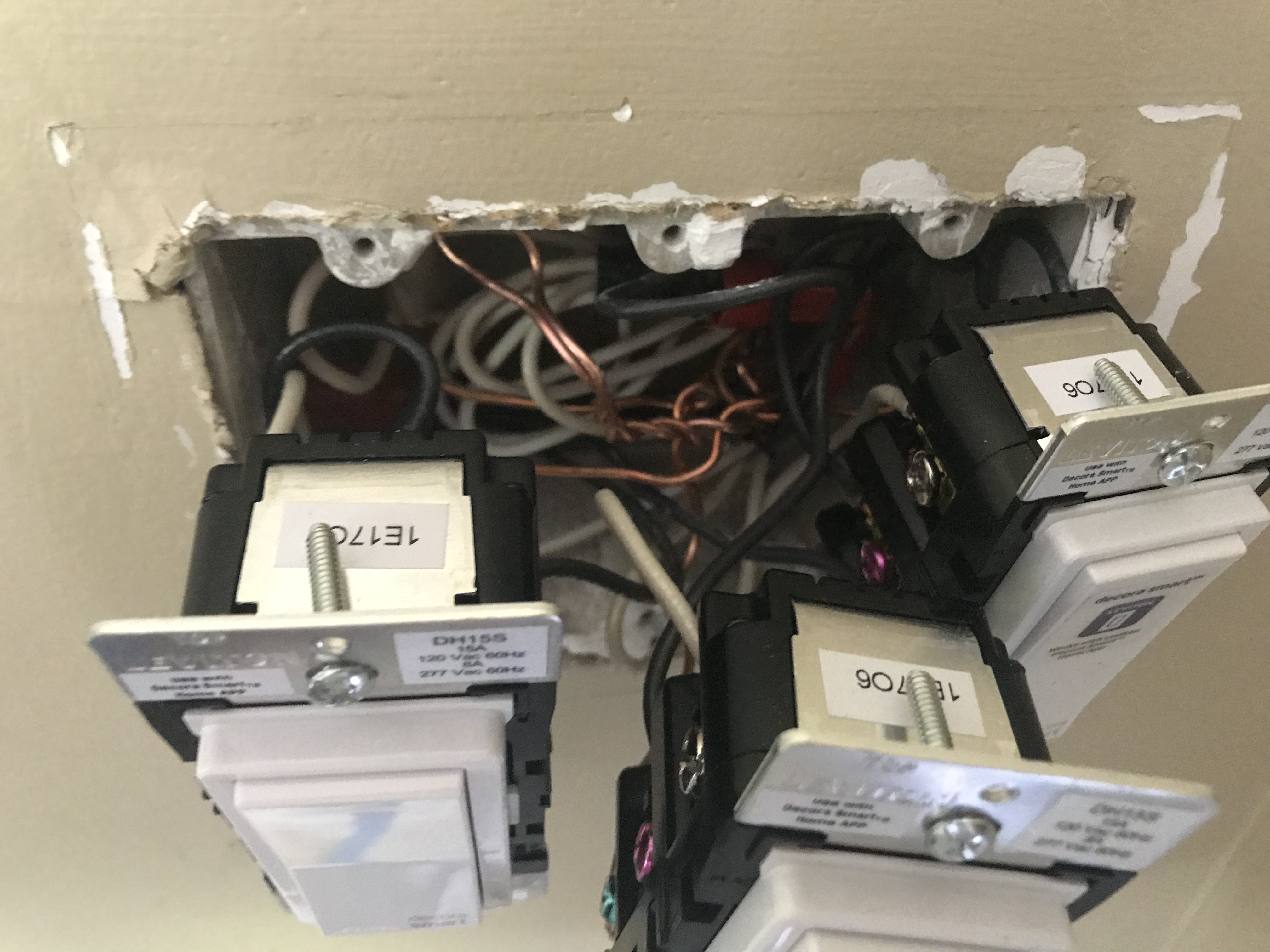
When I was looking at the schematics for the CY8CKIT-044 I noticed that the KXTJ2-1009 had one of the pins attached to the PSoC P1[6]. Even better that pin was labeled “INT”. In the original PSoC FreeRTOS project I polled the values from the accelerometer, which is almost always a bad idea.
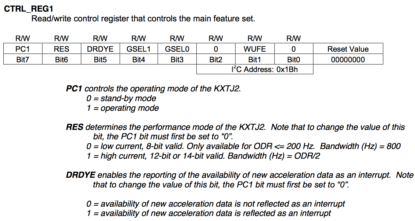
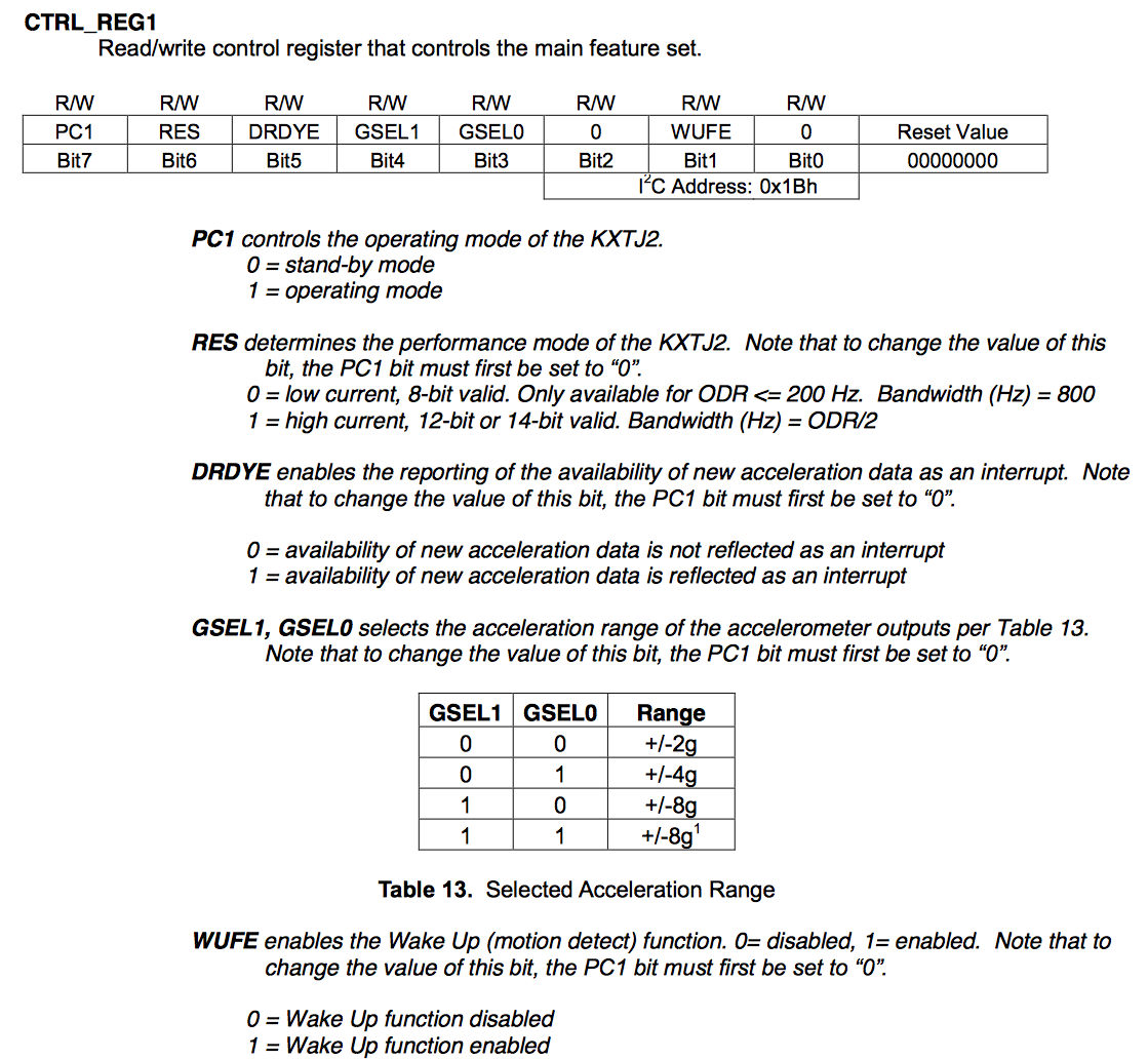
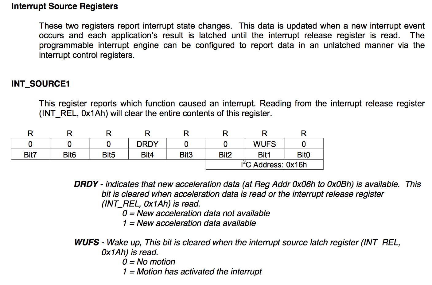
Then when you look in the data sheet you see that you ask for an interrupt when the data is ready “DRDYE”
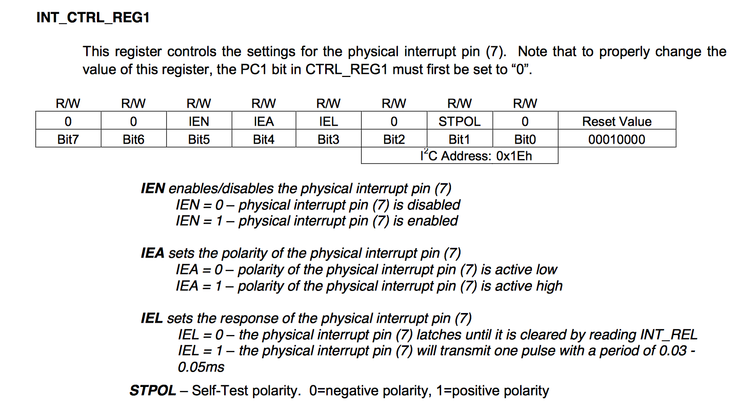
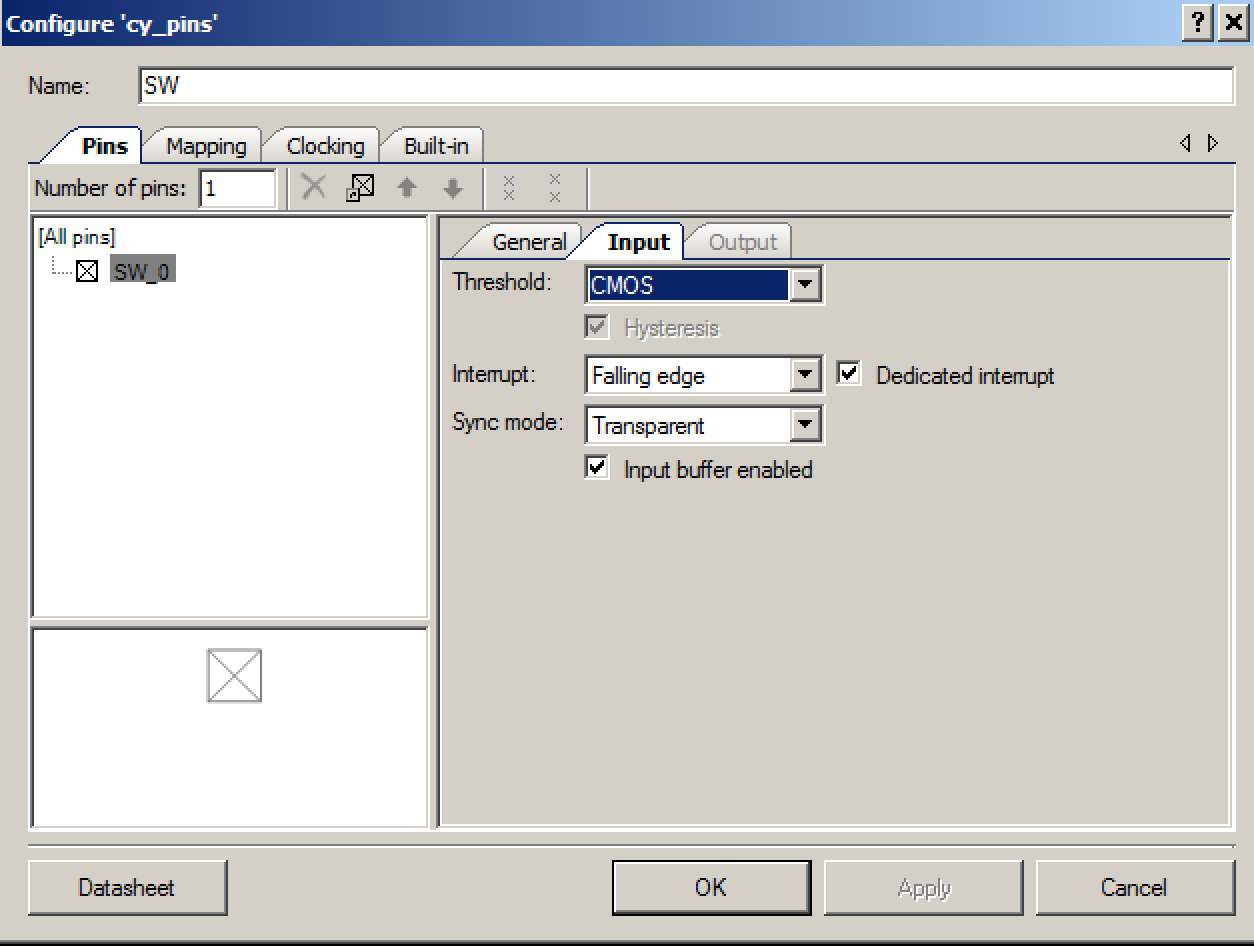
And you can program the INT pin to behave how you want. I chose:
- IEN=1 (Enable interrupts)
- IEA=1 (Make the interrupt active high)
- IEL=1 (Pulse the pin)
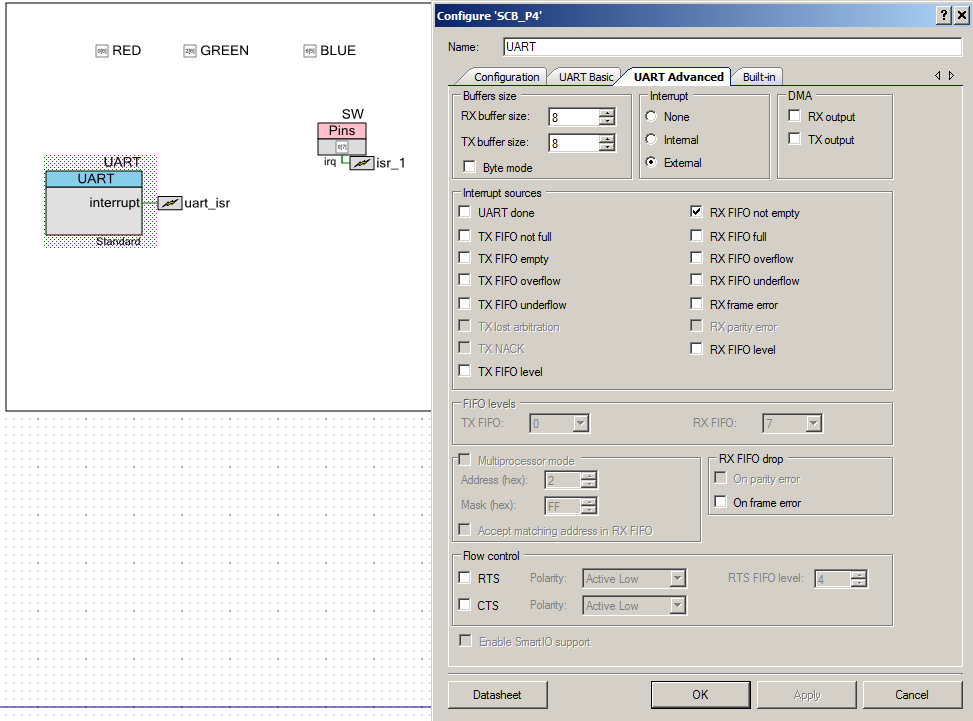
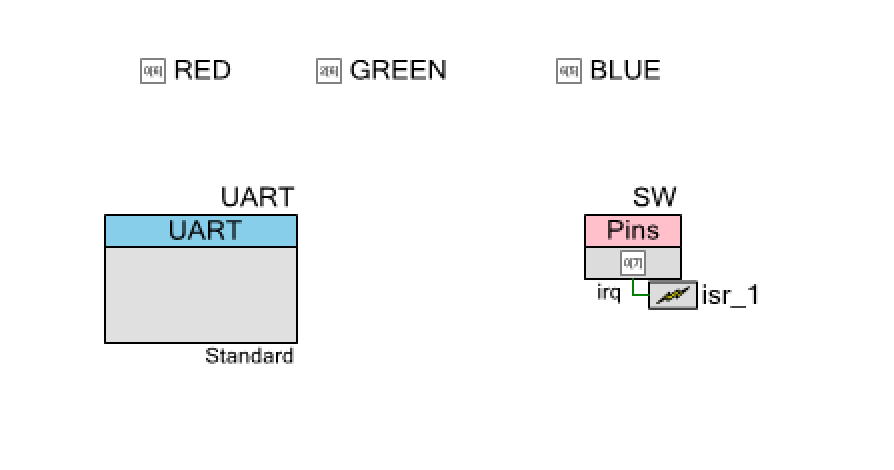
After I figured all of that out, I modify the PSoC FreeRTOS Creator schematic to have the accel_int_pin (aka P1[6]) attached to an interrupt.
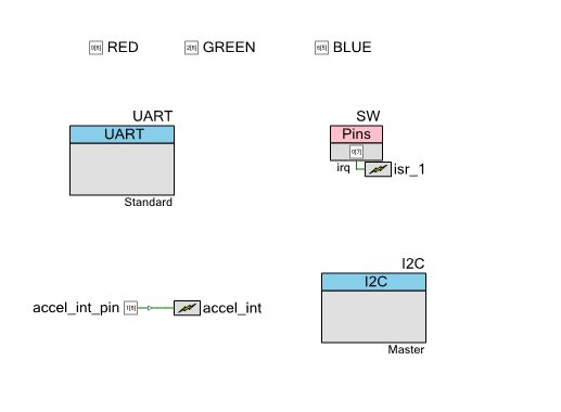
Then I write an ISR to handle the interrupt, which just resets the pin interrupt and sets a semaphore.
CY_ISR(accelIntHandler)
{
    accel_int_pin_ClearInterrupt();
    xSemaphoreGiveFromISR(accelIntSemaphore,NULL);
}
Finally register the interrupt and the start the semaphore
   accelIntSemaphore = xSemaphoreCreateBinary(); // Signal from the Accel that it is ready
   accel_int_StartEx(accelIntHandler);
Using the “kxtj2.h” Header File
When I looked on the Kionix website for the KXTJ2-1009 datasheet I noticed that there was a download link… which I assumed would take me to a place where I could download the datasheet.

But when I go to the download page I got the pleasant surprise of finding a bunch of driver files… but even better there was a “Register Definitions .h/.py”
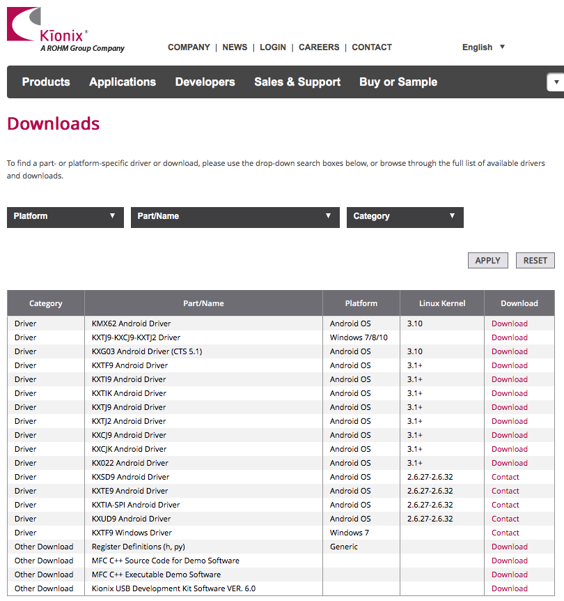
This file had a bunch of #defines for the registers in the chip.
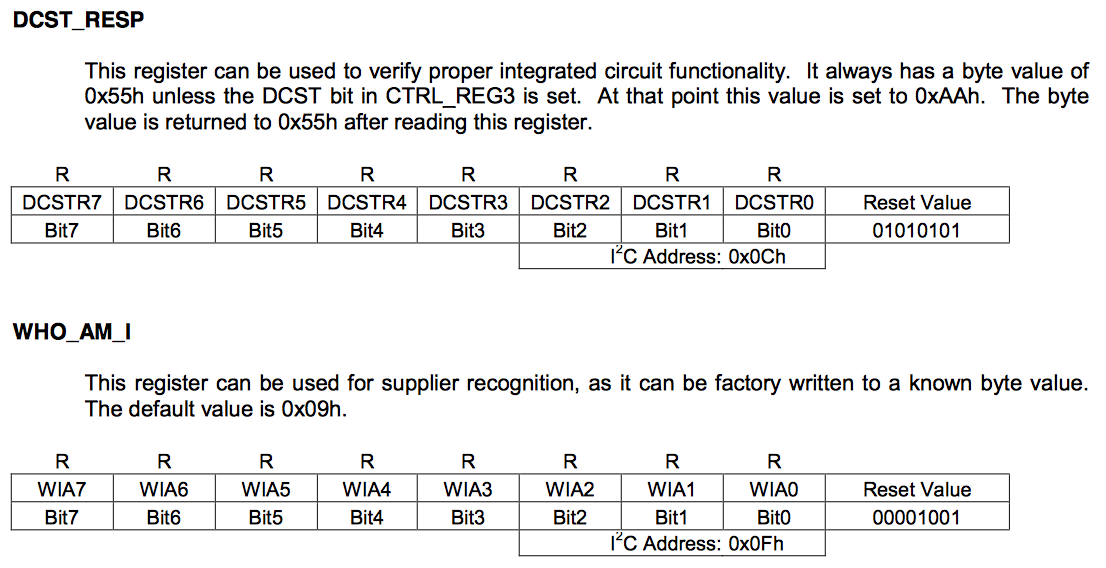
/* registers */
// output register x
#define KXTJ2_OUTX_L 0x06
#define KXTJ2_OUTX_H 0x07
// output register y
#define KXTJ2_OUTY_L 0x08
#define KXTJ2_OUTY_H 0x09
// output register z
#define KXTJ2_OUTZ_L 0x0A
#define KXTJ2_OUTZ_H 0x0B
// This register can be used to verify proper integrated circuit functionality
#define KXTJ2_DCST_RESP 0x0C
// This register can be used for supplier recognition, as it can be factory written to a known byte value.
#define KXTJ2_WHO_AM_I 0x0F
// This register reports which function caused an interrupt.
#define KXTJ2_INT_SOURCE1 0x16
// This register reports the axis and direction of detected motion
#define KXTJ2_INT_SOURCE2 0x17
// This register reports the status of the interrupt
In addition it has the the bit fields for the registers
// 12.5Hz
#define KXTJ2_DATA_CTRL_REG_OSA_12P5 (0x00 << 0)
// 25Hz
#define KXTJ2_DATA_CTRL_REG_OSA_25 (0x01 << 0)
// 50Hz
#define KXTJ2_DATA_CTRL_REG_OSA_50 (0x02 << 0)
// 100Hz
#define KXTJ2_DATA_CTRL_REG_OSA_100 (0x03 << 0)
// 200Hz
#define KXTJ2_DATA_CTRL_REG_OSA_200 (0x04 << 0)
// 400Hz
#define KXTJ2_DATA_CTRL_REG_OSA_400 (0x05 << 0)
// 800Hz
#define KXTJ2_DATA_CTRL_REG_OSA_800 (0x06 << 0)
// 1600Hz
#define KXTJ2_DATA_CTRL_REG_OSA_1600 (0x07 << 0)
// 0.78Hz
#define KXTJ2_DATA_CTRL_REG_OSA_0P781 (0x08 << 0)
// 1.563Hz
#define KXTJ2_DATA_CTRL_REG_OSA_1P563 (0x09 << 0)
// 3.125Hz
#define KXTJ2_DATA_CTRL_REG_OSA_3P125 (0x0A << 0)
// 6.25Hz
#define KXTJ2_DATA_CTRL_REG_OSA_6P25 (0x0B << 0)
To use it all I did was add it to my project by right clicking on Header Files and selecting “Add–>Existing Item”
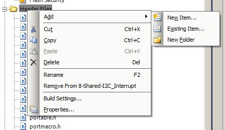
Then I add the include “ktxk2.h” to the includes
#include "kxtj2.h"
Finally I can use the #define names instead of the hardcoded values for example to reset the chip you can write to the KXTJ2_CTRL_REG with the value KXTJ2_CTRL_REG _SRST
    setupData[0] = KXTJ2_CTRL_REG2_SRST; // Software reset
    mytransaction.i2cm_register = KXTJ2_CTRL_REG2;
Updates to the Accelerometer Task
With all of the updates in place I can now make the modifications to the PSoC FreeRTOS accel_Task to use the new interrupt structure. The first thing to do is write into the reset register to force a software reboot. The datasheet says that you need to:
- Write 0x00 into the CTRL_REG1
- Write KXTJ2_CTRL_REG2_SRST into KXTJ2_CTRL_REG2
- Then WAIT until the value in KXTJ2_CTRL_REG2 is 0x0
// Setup for initialization
uint8_t setupData[1];
mytransaction.i2cm_method = I2CM_WRITE;
mytransaction.i2cm_byteNum = 1;
mytransaction.i2cm_doneSemaphore = mySemaphore;
mytransaction.i2cm_bytes = setupData;
// reset the accelerometer
setupData[0] = 0b00000000;
mytransaction.i2cm_register = KXTJ2_CTRL_REG1;
i2cm_runTransaction(&mytransaction);
setupData[0] = KXTJ2_CTRL_REG2_SRST; // Software reset
mytransaction.i2cm_register = KXTJ2_CTRL_REG2;
i2cm_runTransaction(&mytransaction);
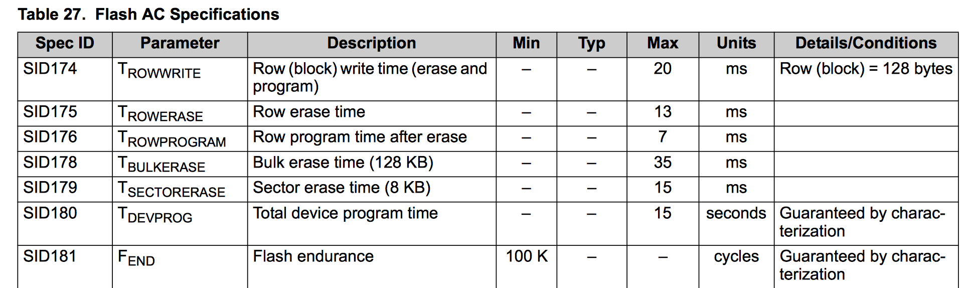
vTaskDelay(10); // From the datasheet power up time
while(1) // delay until the accelerometer is reset
{
mytransaction.i2cm_method = I2CM_READ;
mytransaction.i2cm_register = KXTJ2_CTRL_REG2;
i2cm_runTransaction(&mytransaction);
if(setupData[0] & KXTJ2_CTRL_REG2_SRST)
{
vTaskDelay(10); // backup 10 ms
}
else
break;
}
After the accelerometer chip is reset, then initialize the chip
    // initialize the interrupt
    setupData[0] = KXTJ2_INT_CTRL_REG1_IEN | KXTJ2_INT_CTRL_REG1_IEA | KXTJ2_INT_CTRL_REG1_IEL;
    mytransaction.i2cm_register = KXTJ2_INT_CTRL_REG1;
    i2cm_runTransaction(&mytransaction);

    // initialize the  DATA_CTRL_REG
    setupData[0] = KXTJ2_DATA_CTRL_REG_OSA_12P5;
    mytransaction.i2cm_register = KXTJ2_DATA_CTRL_REG;
    i2cm_runTransaction(&mytransaction);

    // Initalize the acceleromter CTRL_REG_1
    setupData[0] =   KXTJ2_CTRL_REG1_PC | KXTJ2_CTRL_REG1_RES | KXTJ2_CTRL_REG1_DRDYE | KXTJ2_CTRL_REG1_GSEL_2G  ;
    mytransaction.i2cm_register = KXTJ2_CTRL_REG1;
    i2cm_runTransaction(&mytransaction);

    // Setup for repeated reads
    mytransaction.i2cm_method = I2CM_READ;
    mytransaction.i2cm_register = 0x06;
    mytransaction.i2cm_byteNum = sizeof(myData);
    mytransaction.i2cm_doneSemaphore = mySemaphore;
    mytransaction.i2cm_bytes = (uint8_t *)&myData;
After that you can wait for the semaphore, then get the data
while(1) // Run the same transaction over and over
{
xSemaphoreTake(accelIntSemaphore,portMAX_DELAY);
i2cm_runTransaction(&mytransaction);
myData.x /= 16; // The KXTJ2 Datasheet say lower 4 bits are X
myData.y /= 16; // The KXTJ2 Datasheet say lower 4 bits are X
myData.z /= 16; // The KXTJ2 Datasheet say lower 4 bits are X
xs = (myData.x < 0? -1:1); // Find the XSign
ys = (myData.y < 0? -1:1); // Find the YSign
zs = (myData.z < 0? -1:1); // Find the ZSign
// The 1024 is a hardcode based on the range of the acceleromter
x = (int)((float)myData.x / 1024.0 * 10.0) * xs; // Turn it into integer G * 10
y = (int)((float)myData.y / 1024.0 * 10.0) * ys; // Turn it into integer G * 10
z = (int)((float)myData.z / 1024.0 * 10.0) * zs; // Turn it into integer G * 10
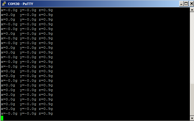
// Format data in x.x
sprintf(buff,"x=%s%d.%dg\ty=%s%d.%dg\tz=%s%d.%dg\n",(xs<0?"-":""),x/10,x%10,(ys<0?"-":""),y/10,y%10,(zs<0?"-":""),z/10,z%10);
UART_UartPutString(buff);
}
As always you can git this PSoC FreeRTOS project at the IoT Expert GitHub site or git@github.com:iotexpert/PSoC-FreeRTOS-Examples.git The project name is “8-Shared-I2C_Interrupt”
Topic
Description
FreeRTOS: A PSoC4 FreeRTOS Port
An introduction to making FreeRTOS work on PSoC 4
FreeRTOS PSoC Examples
Using multiple tasks in FreeRTOS
FreeRTOS Queue Example
Using a queue to communicate between tasks
PSoC 6 FreeRTOS - The First Example
Booting FreeRTOS on PSoC 6
FreeRTOS Binary Semaphore
An first example of a binary semaphore
FreeRTOS Binary Semaphore (Part 2)
Removing polling in the UART Task
FreeRTOS Counting Semaphore
An example using a counting semaphore
PSoC FreeRTOS
Reading I2C Sensors with a shared I2C Bus
PSoC FreeRTOS Task Notify
A light weight scheme to replace Semaphores
PSoC FreeRTOS Task Notification Values
A very light weight method to transfer one word of information into a task


