Particle Photon: Elkhorn Creek Depth

Summary

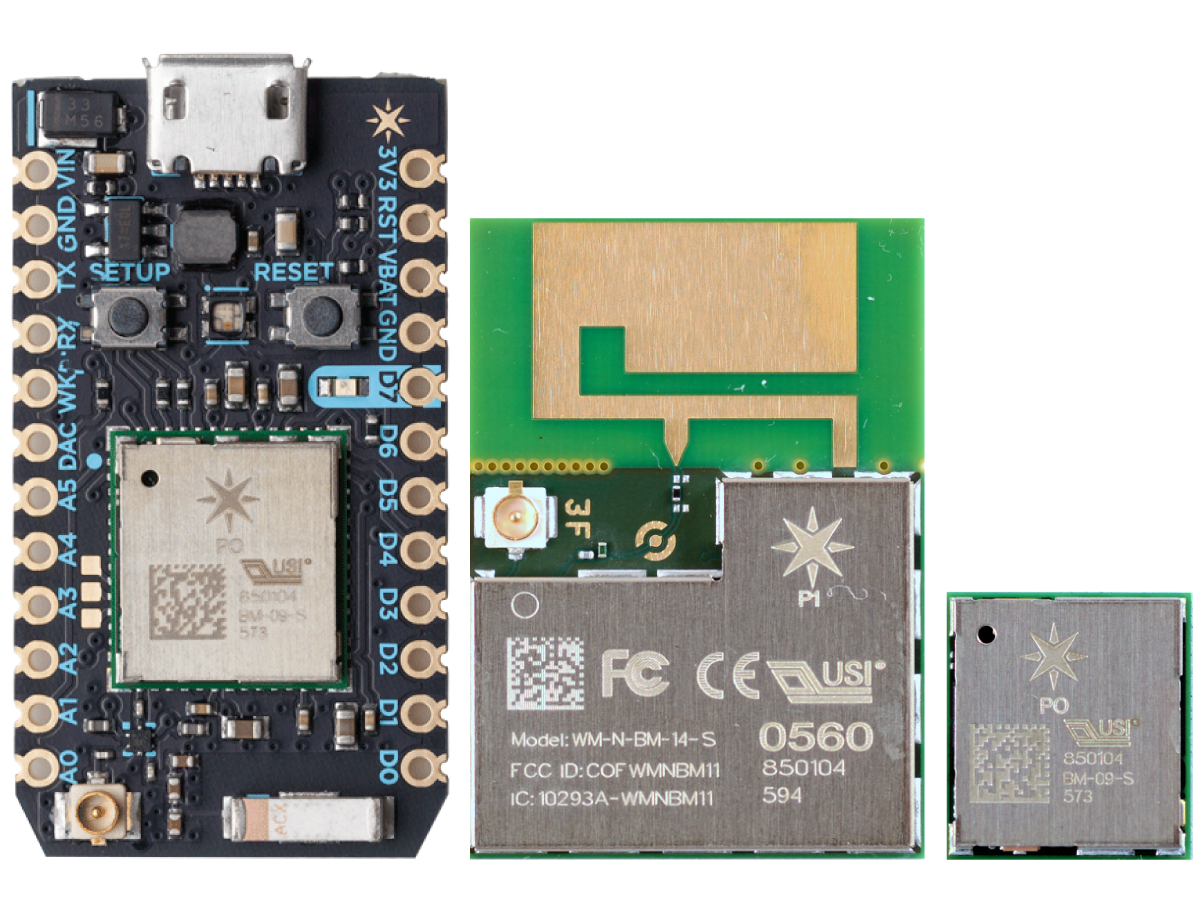
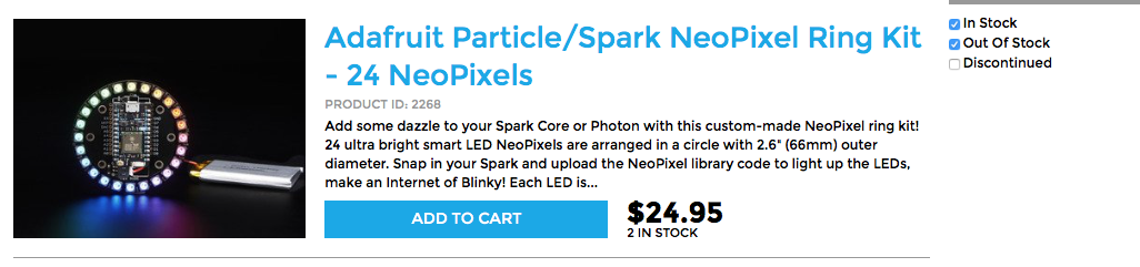
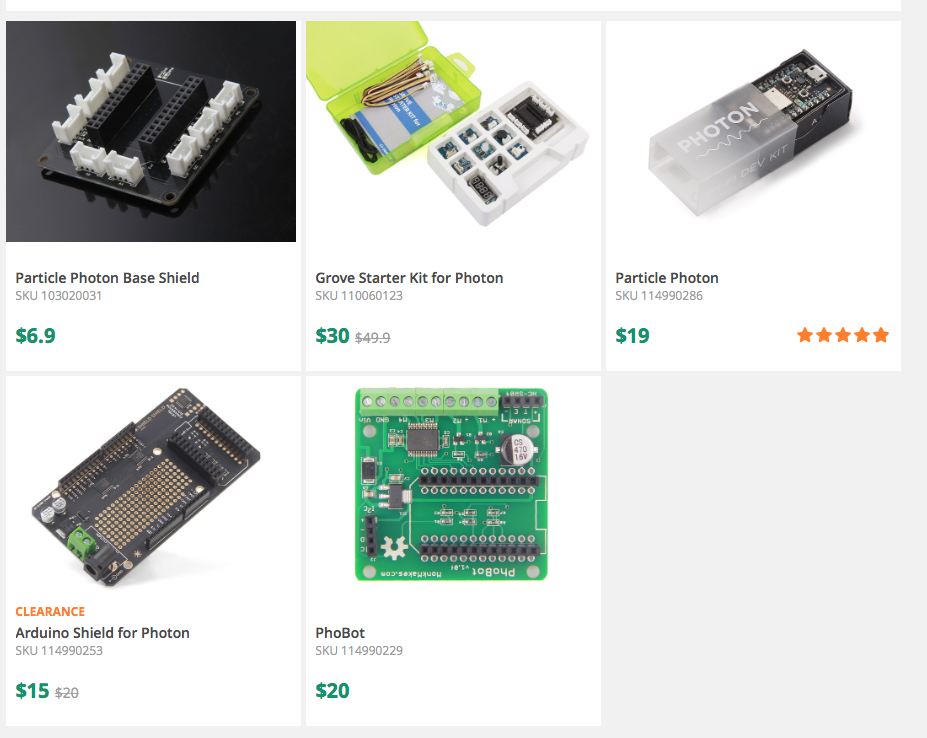
In the previous article I showed you all of the components of the Particle Photon Ecosystem.  All that is cool.  But what can you build?  I have written extensively about the Elkhorn Creek in my backyard, and the system that I built to monitor the water level.  As part of that series of articles I explained that I have a 4-20ma current loop that turns pressure into water level read here .  In this article I will:

  • Attach the Photon to my Creek System Current Loop
  • Write the Firmware in the Particle Cloud IDE to publish W
  • Send events to the Particle Cloud & monitor
  • Use Webhooks to send the data to ThingSpeak.com

Attach Particle Photon to Creek System

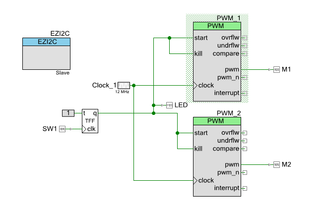
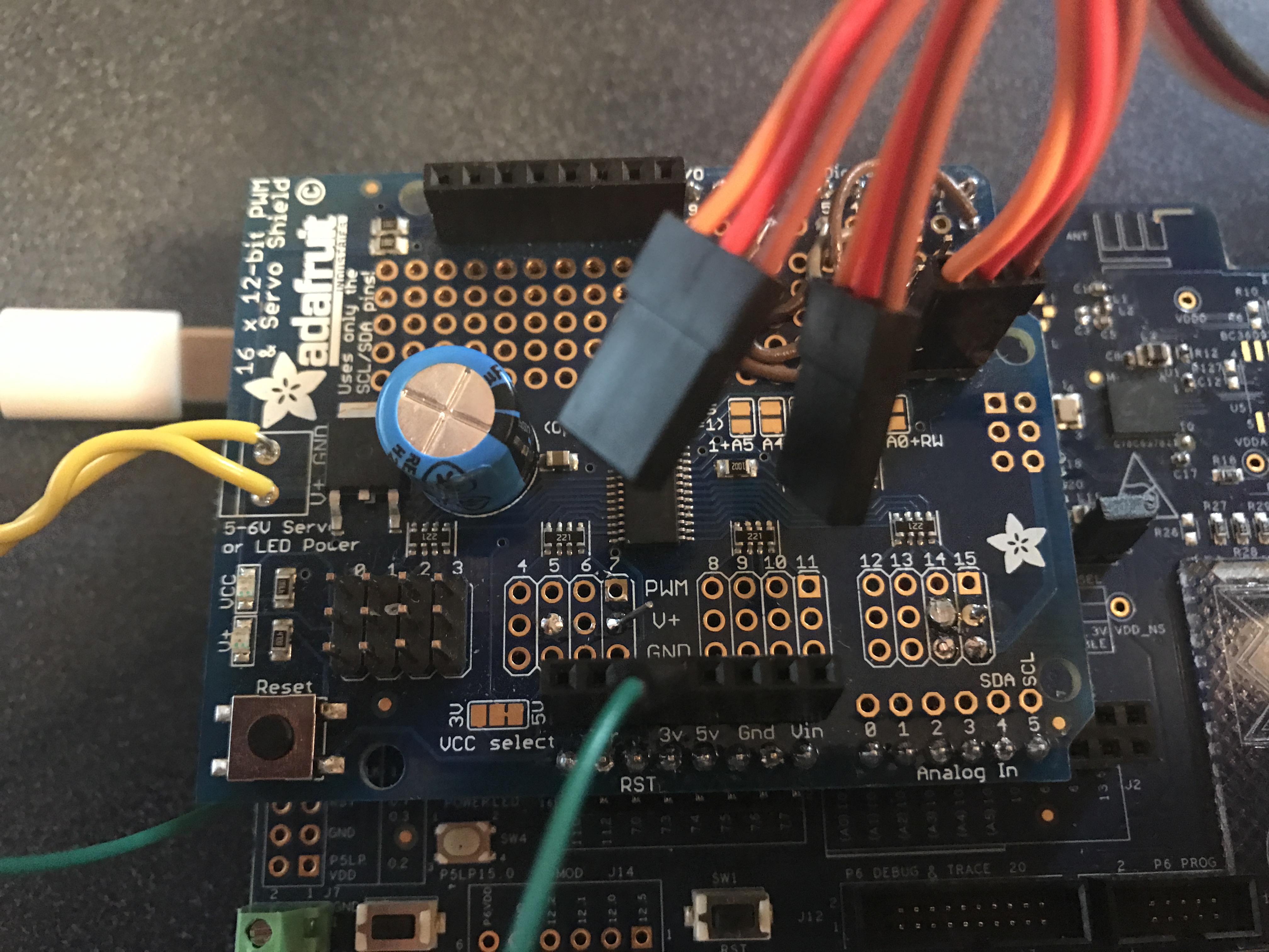
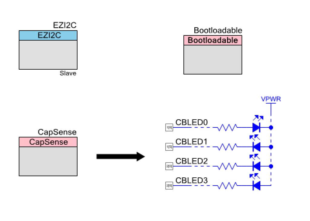
To interface to a 4-20mA current look you just attach it to a 51.1 ohm resistor to serve as a trans-impedence amplifier.  Here is the PSoC Creator schematic for the board:  Using this schematic, the system will generate a voltage between (51.1 Ohms * 4ma = 204.4mV) and (51.1Ohm * 20mA = 1022 mV).   This voltage can then be attached to an Analog To Digital Convertor, then converted digitally into a Pressure, then a water depth.

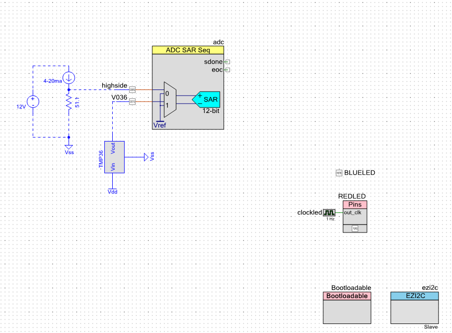
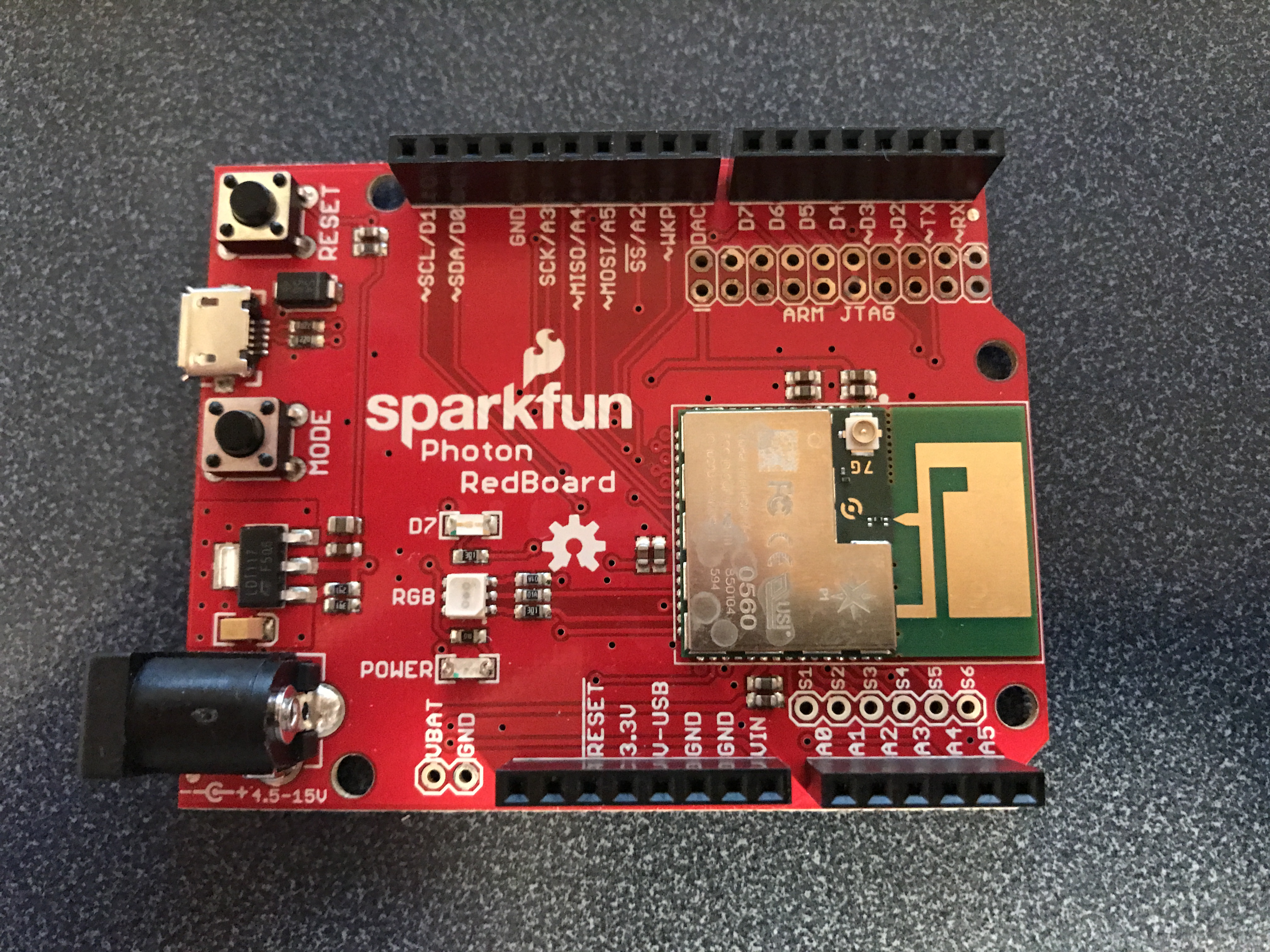
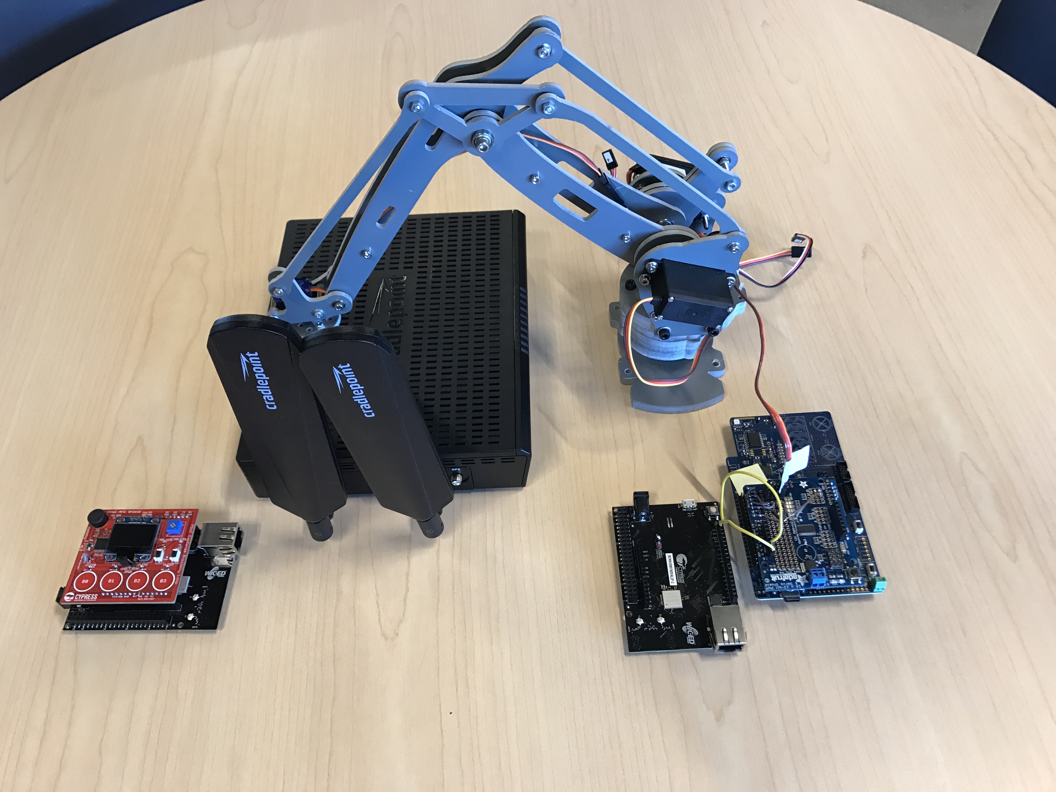
I decided that the easiest thing to do with the Particle Photon was to attach the pin A0 to the highside input.  This was easy as I put a loop on the Creek Board.  The loop is labeled “PRES”.  The picture is a bit ugly as I was standing in the dark in the rafters of my barn.  Sorry.

Particle Photon attached to Elkhorn Creek Water Level 1.1

Particle Photon Firmware

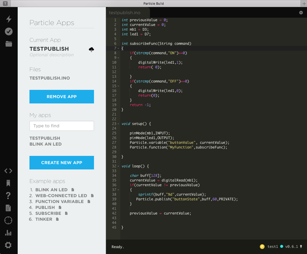
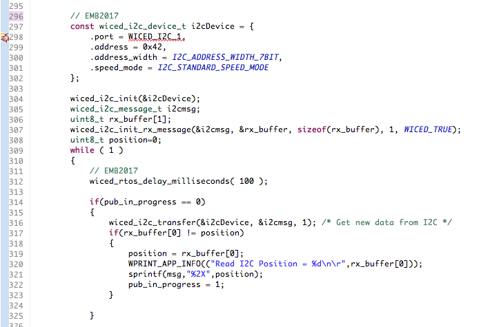
When you look at the main loop of the firmware, lines 23-40 it does three things

  • Reads the ADC voltage on Pin A0
  • Applies an Infinite Impulse Response Filter (IIR) with coefficients of 7/8 and 1/8.  This is low pass filter.
  • Turns the voltage into depth.  This is done by turning (4-20ma) into (0-15 psi) then PSI into Feet

Then, on lines 34-39, I use the system time to figure out if it is time to publish again.  I publish every “INTERVAL”.

In order to test the Particle Cloud interface to the Photon, I setup all of the intermediate calculation of depth as “Particle.variable”s which allows me to inspect them remotely.

uint32_t nextTime; // when do you want to publish the data again
const uint32_t INTERVAL = (5*60*1000); // every 5 minutes in milliseconds
const double  MVPERCOUNT = (3330.0/4096.0); // 3300mv and 2^12 counts
uint32_t current;
uint32_t filter=0;
double depth;
double percent;
double psi;
double voltage;
double percentTemp;

void setup() {
    nextTime =  millis() + INTERVAL;
    // setup variables so that they can be polled
    Particle.variable("filter",filter);
    Particle.variable("adc",current);
    Particle.variable("percent",percent);
    Particle.variable("voltage",voltage);
    Particle.variable("psi",psi);
    Particle.variable("depth",depth);
}

void loop() {
   
   char buff[128];
   
    current = analogRead(A0);
    filter = ((filter>>3) * 7) + (current>>3); // IIR Filter with 7/8 and 1/8 coeffecients
    voltage  = ((double)filter) * MVPERCOUNT; // Convert ADC to Milivolts
    percent = ( voltage - (51.1*4.0) ) / (51.1 * (20.0-4.0)); // 51.1 ohm resistor... 4-20ma 
    psi = percent * 15.0; // Range of pressure sensor
    depth = psi / 0.53; // Magic 0.53psi per foot

   if(millis() > nextTime)
   {
        sprintf(buff,"%.1f",depth);
        Particle.publish("CreekDepth",buff);
        nextTime = millis() + INTERVAL;
   }
}

Sending Events to the Particle Cloud & Monitor

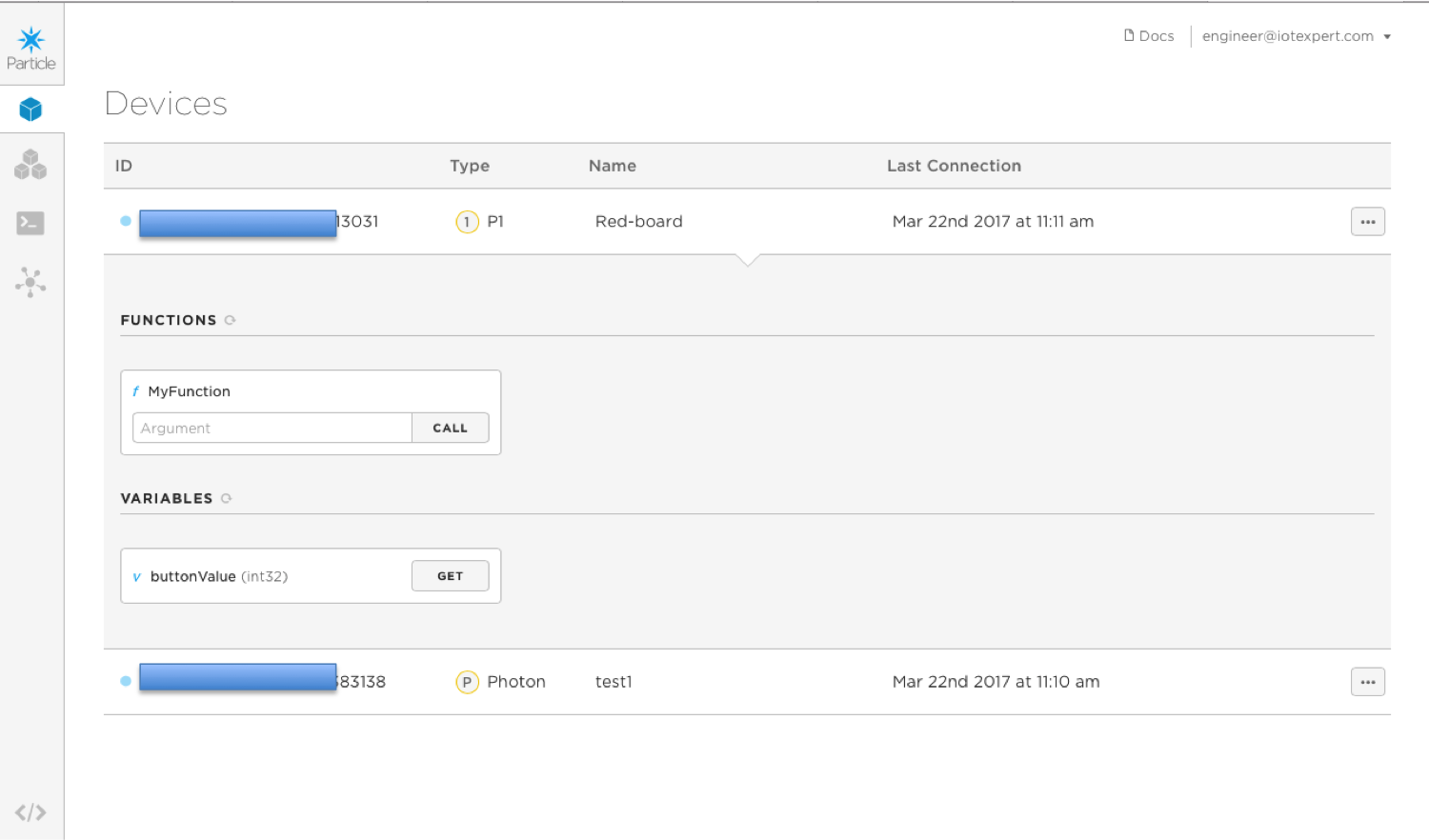
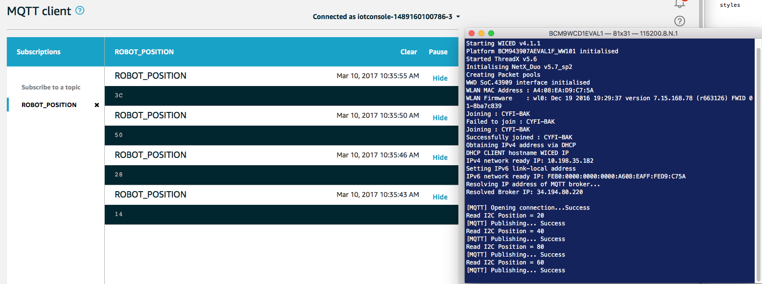
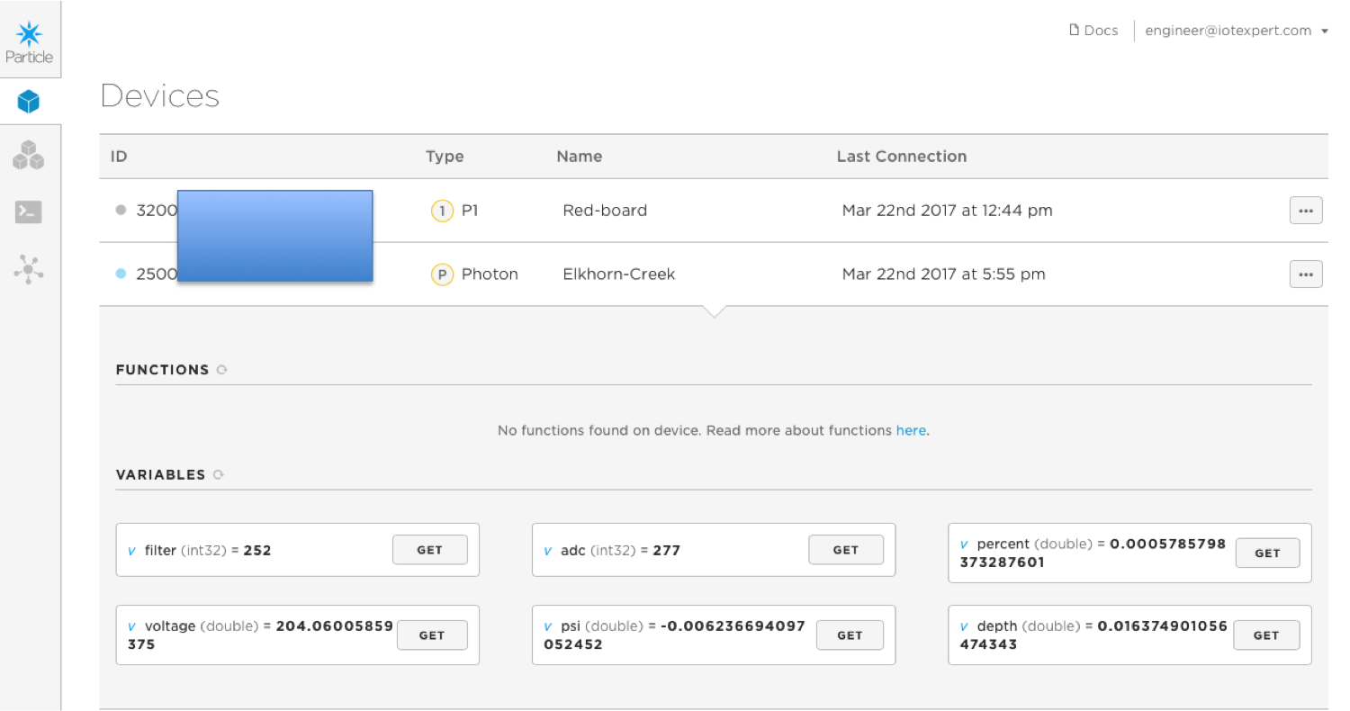
Once I flashed the firmware with the very cool Over-The-Air Bootloader, I go to the Particle Console and click on my device.  As soon as I do that I see the “Particle.variable”s that I defined in the firmware.  One by one I press “get” and after a second the data is displayed on the screen.  I am not exactly sure how the exactly works, but it is cool.

Particle Cloud Device Console

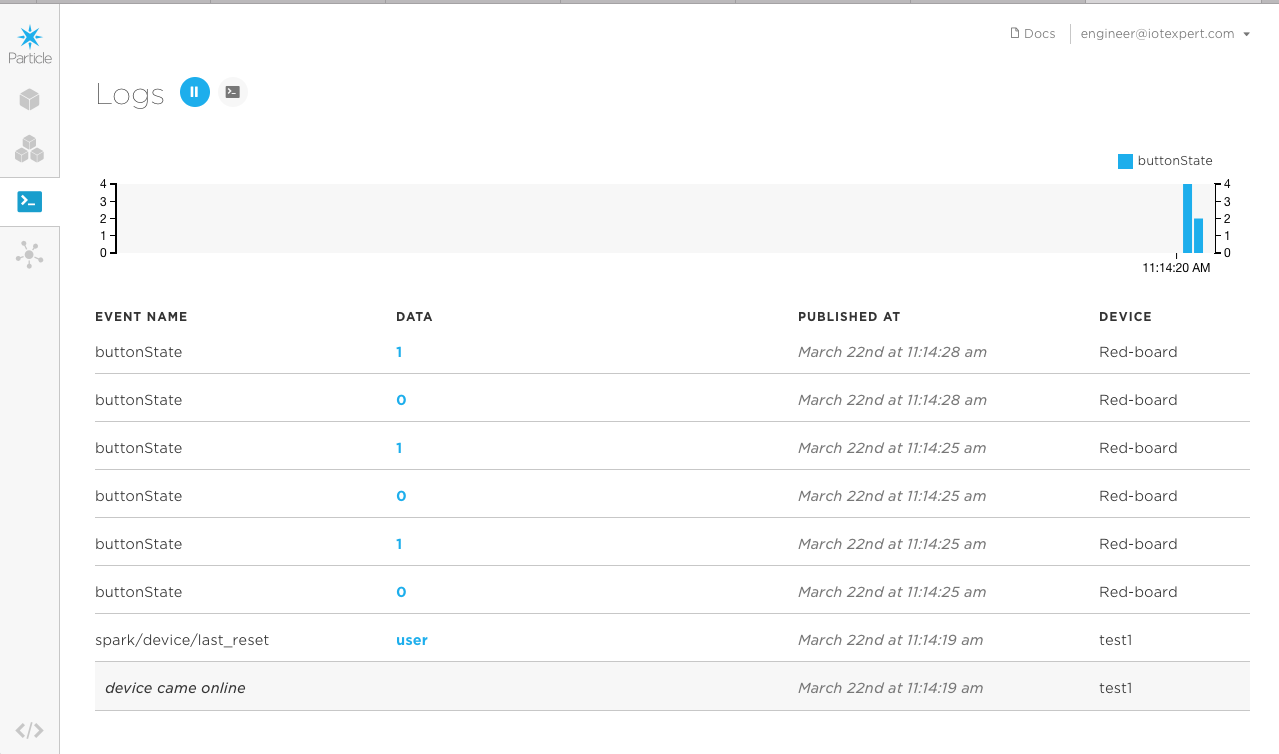
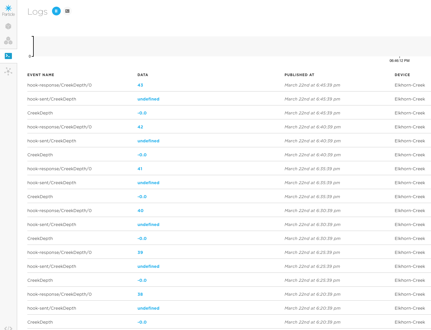
After inspecting the variables, I go the Logs page and look to see what the events are.  You can see that every 5 minutes (about) there is an event called “CreekDepth” with a -0.0 or so. That is good as it means that the Particle Photon is publishing regularly.  The answer is 0.0 (or about 0.0) as the Elkhorn Creek if not doing anything right now.  The other events are part of the web hook that I setup (and will talk about in the next section).

Particle Cloud Device Event Log

Using WebHooks to send data to ThingSpeak.com

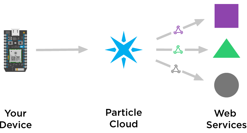
Unless I am missing something, the Particle Cloud does not store your actual data.  They do have a mechanism to take Events from your devices and trigger a “WebHook”.  This is basically a RESTFul API call to another cloud.

Particle Cloud Webhooks

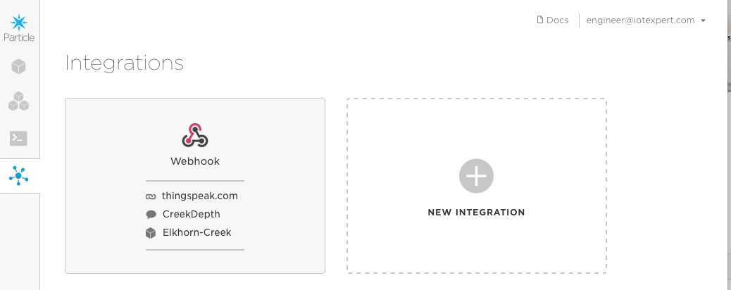
They call these “integrations” and you configure them on the Console.  When you press “Integrations” you end up with this screen which gives you the option of editing a current webhook or creating a new one.

Particle Cloud Integrations

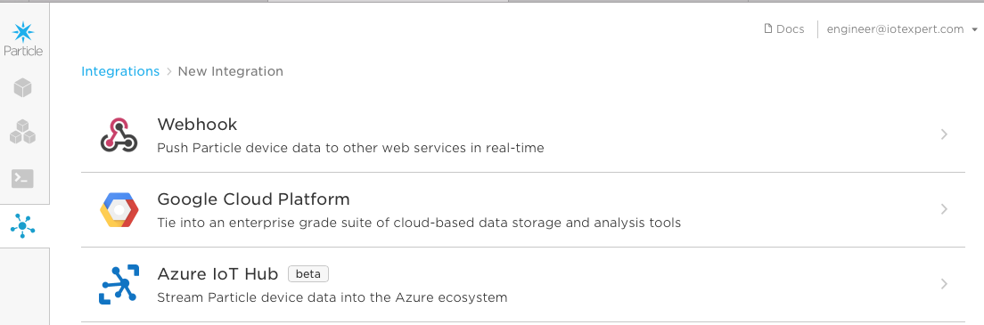
When you click on “new integration” it gives you the option of connecting to Google, Microsoft Azure or Webhook.  I havent tried Google or Azure so for this article Ill stick with a Webhook.

Particle Cloud New Integration

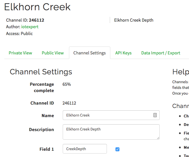
I started with a WebHook to the ThingSpeak Cloud (because they show a nice example in the documentation).  ThingSpeak is run by the MathWorks people (same as Matlab).  They call ThingSpeak “an open IoT with Matlab Analytics”.  OK sounds cool.  In order to use it to collect and display data I start by creating a new account.  Then I click on the “New Channel” button to create an “Elkhorn Creek Depth” channel.  On this screen I say that there will be only one field “CreekDepth”.

ThingSpeak Create New Channel

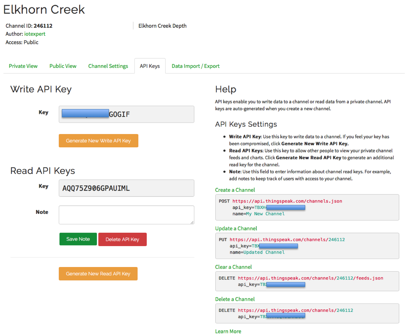
In order to write data into this channel you need to have the API keys which give your Restful API call the authority to write into the database.  Press “API Keys” and you will see this screen.

ThingSpeak Channel API Keys

Now that I have an active channel (and I know the channel number and API write key) I go back to the Particle Cloud Integrations tab and create a Webhook.

Particle Cloud Edit Integration

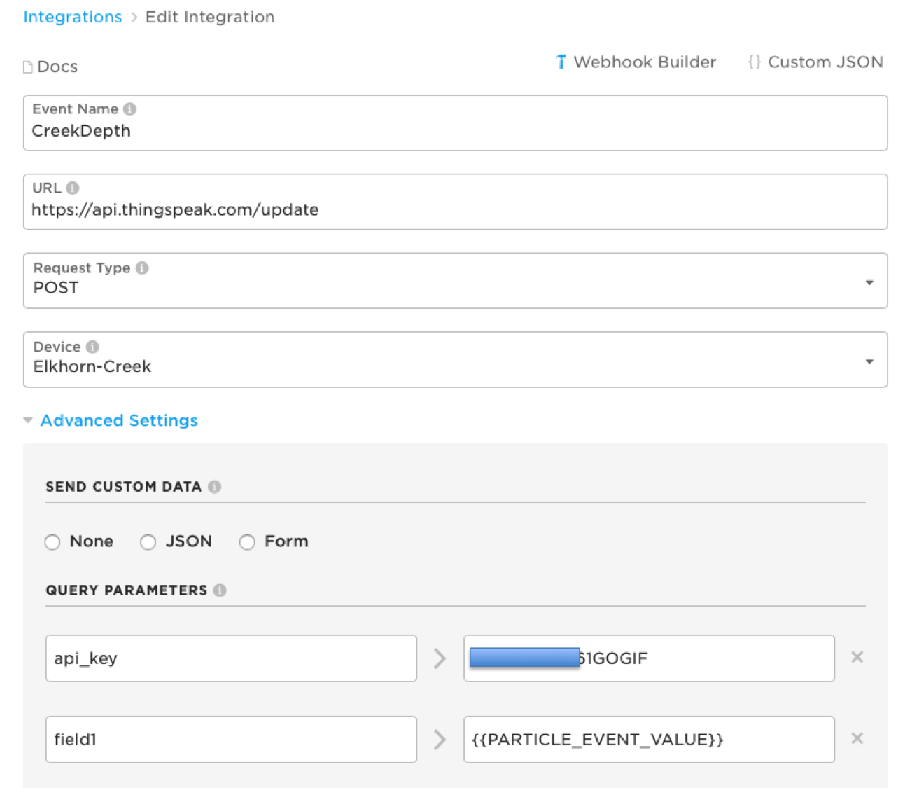
Each time the “CreekDepth” event occurs, the Particle Cloud will do an API call to the ThingSpeak cloud and insert the new data.  On the ThingSpeak Cloud there is a chart of the data, and a handy-dandy way to insert the chart into your webpage.  Here it is for the Elkhorn Creek showing the last 6 hours of data which is flat at the time of this writing, but maybe when you read this page it will be raining in Kentucky and you will see something interesting.

I guess at this point I have a number of questions which I will leave to the future:

  • Exactly what is the form of the request made to the ThingSpeak cloud?
  • What is the mapping between the event –> API Request
  • What is the protocol for Particle.variables?
  • How does the Microsoft integration work?
  • How does the Google integration work?
  • How do I save power on the Photon?

I suppose Ill leave these questions to future posts.  If you have other questions leave them as I comment and Ill take a crack at trying to figure them out.

Particle Photon: An Overview of the Particle Ecosystem

Summary

Over the last few days I have spent some time with the Particle Photon and looking around at the Particle Cloud, the Development Kits, the Documentation and Development Tools.  Fundamentally, Particle has built a very ambitious end-to-end cloud development platform.  I think that they have everything necessary to built a complete IoT solution into your system.  Obviously, I like them because they use a Cypress 43362 WICED WiFi chip as the core of their solution, but the rest is cool as well.  Particle also offers a cellular connectivity solution using uBlox, but I didn’t try that.  In this article I will give you a brief introduction to all of the components of their ecosystem including:

  • Particle Photon WiFi
  • Particle Photon Development Kits
  • Particle Photon Development Environment
  • Particle Photon Support Tools
  • Documentation
  • Particle Cloud Console

To develop with Particle you write your firmware in C++ with an Arduino library clone (many/most? of the APIs and libraries that you know and love are ported into the system).  The libraries also include a bunch of APIs for transferring actions and data to/from the cloud.  Once you have written the firmware you can flash you board either directly through the USB port or through the Cloud over-the-air bootloader (which works great)

Particle Photon WiFi

Particle makes two modules, called P0 ($10) and P1, ($12) which you can build into your system.  Both are FCC certified modules that use the Cypress 43362 WICED WiFi chip which is 2.4GHz 802.11a/b/g/n paired (unfortunately) with a STM MCU to run WICED & the Photon Environment.  Both of the modules are PCB circuit boards with QFN style pads on the bottom that let you solder them into your system.  The P0 is smaller (11mm x 12mm) but needs an antenna, and P1 is a bit bigger (28mm x 20mm) but has a PCB Antenna and SMA connector.  Here is a picture which I borrowed from the Particle Website.  The P0 is on the right, the P1 is in the middle, then on the left is a development kit with the P0 soldered into it.

Particle Photon WiFi

Particle Photon Development Kits

Photon makes essentially one basic development board (shown above on the left) as well as a bunch of different support boards and package deals.  The basic development kit is $19 and has a Photon P0, an antenna, an SMA connector for an external antenna, two buttons (reset and setup), one user LED, a USB programming/power connector and 100 mil center pins with the P0 pins broken out.  One very cool feature of the board is that the breakout pins are castellated on the side of the board so that you could solder it directly into your product.

One of the boards that I ended up using was a (now obsolete) SparkFun kit that has a Photon P1 soldered into an Arduino footprint board:

Particle Photon WiFi - SparkFun RedBoard

Here is a screenshot of many of the development kit packages you can buy directly from Photon:

Particle Photon WiFi Development Kits

In addition there are several other makers of support boards including SparkFun, Adafruit and SeeedStudio.

SparkFun Photon Kits

Adafruit:

AdaFruit Photon Kit

SeeedStudio:

SeeedStudio Photon Kits

Particle Photon Development Environment

Particle offers two integrated development environments, one web based and one computer client based on Atom.  Both are approximately Arduino clones… and both work very well.

The web based environment includes a code editor, compiler, over-the-air flash utility. and library utility.  Here is screenshot of one of the programs that I was working on.

Particle Photon Cloud IDEAnd the desktop environment, which works on Windows, Mac and Linux, is very well integrated and “feels” just like the web environment.  I was amazed that as soon as I installed the tool it was connected to the Particle Cloud and to my devices.  I created a very simple blink the led program.  After I pressed the lightning bolt… 15 seconds later my board was bootloaded over the air.  Here is a screenshot from my Mac.

Particle Photon Desktop Client IDE

Particle Photon Support Tools

There are two sets of command line tools that you can use to interact with the Photons, dfu-util and the Particle-cli.

The first is “dfu-util”  which I didn’t know anything about until I started using the Photons.  DFU-UTIL is a USB bootloader host that allows you to update sections of the Photons firmware.  When I took my boards out of the box they had very old system firmware and things were not connecting correctly.  I ended up having to download new system firmware and then install it on the boards.  The instructions were on this website.

The second tool, called the Particle Command Line Interface is also really cool.   Once you install it you can upgrade firmware, send commands, read and write data, call functions etc on your devices.

Particle Command Line Interface

Documentation

The bottom line is the documentation is outstanding, something that is a rare and wonderful thing in the business.  You can find it on their website.  Here is a screenshot of the first page.

Particle Photon Documentation

Particle Cloud

An IoT device isn’t worth much unless it is integrated with the cloud.  Particle provides a bunch of things in their cloud.  In addition they give you the ability to drive data and events into other clouds.  With the Particle Cloud you can

  1. From the cloud, read and write data from devices
  2. Push and retrieve data from your device to the cloud
  3. You can manage and provision devices
  4. You can flash new firmware OTA to your devices

There is a free tier for makers and experiments which includes up to about 25 devices and 250K transactions per month.  Beyond that they have several subscription levels.  In the screen shot below you can see my two devices (one called “Red-board” and one called “test1”).  With this interface I can query the device and run “functions” which are like remote procedure calls.

Particle Cloud

In the console log you can see all of the events pertaining to your device.  In the screenshot below you can see that I changed the state of the button a bunch of times on the “Red-board”.  You can also see where the “test1” board was reset and re-attached to the network.

Particle Cloud

In the next Particle post I will make something…. what?  Im not sure yet.  But Ill think of something.

Embedded World 2017: The Gospel of PSoC & WICED

I am back in Kentucky after an absolutely CRAZY week in Germany at Embedded World.  Looking back on the week I was extraordinarily proud of Cypress.  That was by far the best showing that we have ever had at a trade show.  And I really enjoy spreading the gospel of PSoC & WICED.  I thought that today I might post a few pictures from the week.

First, here is a picture of me delivering the benediction of PSoC & WICED at the end of my talk.

The benediction of PSoC & WICED

The day before setting up and testing the PSoC–>WICED–>Amazon–>WICED–>PSOC–>Robot ARM

Setting up the PSoC & WICED Demo

Some video from my talk… thank you RS Components

One of the Cypress 3.0 Videos

The Germans have a deep and philisophical understanding of the proper use of Pork.  Here is the meat plate at Barfüßer in Nuremberg.

Nuremberg Sausages & Pork in Nuremberg

The show was awesome… and Im glad Im home for a few days.

Embedded World 2017: WICED Controls the Secret New Chip

Summary

It is now Monday morning in Munich.  After flying all night I am here waiting for ride to the show in Nuremberg.  Saturday turned out to be a little bit stressful.  After getting the Servo Motors working correctly I tried to make the final connection between the WICED WiFI Board and the Secret New Chip board via I2C.   But that connection was not working.  Why?  I didn’t know, but all of my theories were bad e.g. does the new chip have a bug in the I2C (nope).  Finally after hours and hours of thinking about it, making logic analyzer traces, trying different boards, etc. I called my friend Greg who said “Oh, if the I2C slave stretches the clock on the 43907 I2C master, it doesn’t work. Don’t you remember that I told you that?”

Fixing the Secret Chip Firmware

The firmware fix was kind of a workaround rather than a permanent fix.  I did two things to try make sure that the new chip didnt stretch the clock.  (I am not sure that either is a guarantee).

First, I increased the speed of the I2C bus.  I doubt that this guarantees that the I2C clock is not stretched, but it seems to work.

Second, I increased the priority of the EZI2C interrupt (though I don’t think that in this case it actually mattered).  This picture shows something interesting about the new chip.  I called the BU manager and he told me that I could say that it is a multicore chip. 

Modifying the Subscriber Application

Now that I have the communication working between the WICED WiFi development kit and the secret new  chip development kit, I need to make a change or two to the Subscriber firmware to send updates to the Robot ARM controller.  One good thing about spending hours trying to figure out why the I2C was not working is that I greatly improved the Subscriber firmware.

In the modified firmware

  • Lines 330-338 setup the I2C bus interface
  • Line 337 defines a two byte buffer that will be sent each time a new message is published.  The first byte is the address in the I2C slave (in this case 0) and the 2nd byte is the value for the new position (in percent)
  • Lines 341-346 are the main loop for the new firmware.  It just waits for the semaphore in the MQTT code to be set, then it prints out the position (line 344), then sends it to the slave (line 345-346)

The last things that needs to be changed is to set the semaphore when a new message is received from the MQTT Message Broker:

  • When the message is received
  • Turn the ASCII hex value into a Integer (line 116)
  • Set the semaphore to tell the main loop to send the data (line 117)

Conclusion

Everything is done and working… and checked into GitHub.  You can find it at GitHub.com:iotexpert/emb2017.  Come see me talk at Embedded World… as always I am never sure what I will say next, which apparently makes for a good show.  Ill leave you with this image of my office, which is a total disaster area.


Embedded World 2017: The Top Secret New Chip as a Servo Motor Driver

Secret New Chip Driving Motor

Summary

In this article I will take you through the firmware that I will be using to control the Robot Arm Servo Motors.  The Business Unit Manager is being a total pain the neck about letting me tell too much about his new product before the announcement at Embedded World next week.  He is from Indiana, so that probably explains his dogged recalcitrance (just joking… Im from KY and there is a big rivalry).  Anyway.  You will be able to see some things about the new chip if you look closely what I am doing.  My design will have:

  • An EZI2C to support communication with the WICED I2C Master
  • Two PWMs to control two servo motors
  • A connection to the onboard switch and LED to turn the servo PWMs on/off

Building the Servo Firmware

To make the design I first create a new project and the edit the schematic.  In this new chip there is clearly some logic gates as you can see that I control the PWMs with a Toggle Flip Flop.  Basically every time I press the switch it toggles the flip flop and then either starts or kills the PWMs.  This is very handy when you are trying to figure out what is going on with the PWMs and the servos.

As in earlier Cypress chips you double click the component to configure it.  Ill start with the PWMs and observe that we have another new GUI for configuring PWMs.  The servo motors want a pulse that is between 1 and 2 ms wide at a frequency of 50hz.  My PWM has a 12 Mhz clock input, which is then divided by 4 with the prescaler, and finally by 60000 by the PWM itself.  That equation yields a period o.052 kHz which (also known as 52hz) as PSoC Creator helpfully tell us.  By setting the compare to 3000 I will end up with a pulse of 1MS (about).

Configure the TCPWM

In order to configure the PWM to have the start/kill inputs, I select the Advanced tab and setup the PWM to start when the toggle flip flop goes low.  And I get it to kill (stop) when the toggle flip flop goes high.  I choose active low because the LED that is attached to the circuit to indicate the state to the user is active low.

Advanced PWM Configuration

Next I configure the EZI2C by double clicking it.  It looks like there is a new interface for EZI2C as well… but under inspection there is nothing too tricky.

Configuring the EZI2C

Once I have the schematic built, I need to assign the Pins which is done using the DWR Pins Menu (as you did with earlier Cypress chips)

Pin Assignment

Hmmm it looks like the new chip comes in a BGA, and seems to have a bunch of pins.  For the purposes of this demo, I assign the two motor pins too two of the pins on the Arduino Adafruit Servo Shield that I am using to make the connectivity easier.  This was a neat way for me to be able to plug in servo motors and provide them with power from something other than the chip, but still drive them with the chip.  Here is a picture of my shield.

Adafruit Servo Motor Shield

Build the Firmware

The firmware is very simple.

  • Declare a structure to hold the data from the I2C master (lines 8-11)
  • Start & Configure the EZI2C (lines 21-23)
  • Start & the PWMs (lines 24-28)
  • In the main loop, when there is a complete write from the I2C Master, Update the PWM compare values
  • The function convertPercentToCompare calculates the compare value required based on a number 0-100 (aka percent)

Servo Motor Firmware

Testing the Firmware

To test the firmware I use the Bridge Control Panel to issue I2C Commands (as I did in the earlier post).  You can see that I did a list devices.  Then sent several different percents (they are in hex).

Using the Bridge Control Panel to control the Servo Motors

Here screenshot from my oscilloscope where you can see that I entered 0x32 (aka 50%) so the width of the pulse is 1.5ms @ 50Hz.

Servo Motor Pulses on Oscilliscope

And it seems to work pretty well at controlling my Servo Motor Robot ARM.  Nicholas looks a little bit crazy, probably the result of too much Solder smoke?

Nicholas and the Servo Motor Controller

In the next article I will make the final connection to the WICED WiFi kit which will give me end to end connectivity through the Amazon IoT Cloud.

Alan

p.s. I love this new chip, you guys are going to be blown away.

Embedded World 2017: PSoC CapSense –> WICED WiFi MQTT –> Amazon IoT

Summary

In a previous post I showed you how to build a CapSense GUI using the PSoC Analog CoProcessor.  And, in an earlier, post I showed you how to make a WICED WiFi MQTT Publisher App that can send data to the Amazon IoT Cloud.  Now I need to put it all together so that I can I2C read from the CapSense GUI and then publish that data to the Amazon Cloud.  In order to do that I will need to make a few modifications to the Publisher App:

  • Delay 100 ms (meaning the WICED WiFi board is I2C polling)
  • Read the I2C Register 0 on the PSoC Analog CoProcessor Board
  • If the position has changed, then Publish the new position to the Amazon MQTT Message Broker

Here is a picture of the two boards connected together.  If you have a sharp eye you probably noticed that the LED next to B0 is on.  I changed the PSoC Analog CoProcessor firmware to retain the state of the last button press.

PSoC Analog CoProcess and WICED WiFI

Modify the WICED WiFi MQTT Publisher Firmware

If you remember, the Publisher App was built to turn a light on and off when the user pressed the button on the board.  To do this, WICED MQTT Published an ASCII message of either “LIGHT ON” or “LIGHT OFF” that was stored in a char pointer called “msg”.  The original firmware also used the user button to trigger the publishing by setting a semaphore.  I want the board to poll every 100ms the current state of the button, then if it is changed from the last time, publish a message with the new position.  There are several things that need to happen to make this work

  1. Setup the I2C device: (lines 297 –> 307)
  2. Start the infinite loop (line 309)
  3. Delay 100 ms (line 312)
  4. Check to make sure that we are not in the middle of publishing.  The publishing is an asynchronous transaction. (line 314)
  5. Read the I2C register of the PSoC (line 316)
  6. If the position has changed, then setup the message and activate a publish (line 317-322)

WICED WiFi MQTT Firmware

Test the WICED and PSoC Firmware

To test the whole setup I program the board, then attach to the Amazon Cloud MQTT Test Client.  Then I use it to subscribe to the “ROBOT_POSITION” topic.  You can see in the picture below the transactions that I tested:

  • The WICED Development Kit booted
  • WICED I2C read initial position = 20 (0x14)
  • I pressed B2 and it read position =40 (ox28)
  • I pressed B2 and it read position =80 (ox50)
  • I pressed B2 and it read position =60 (ox3C)

Testing the WICED WiFi MQTT Firmware

In the next article I will modify the Subscriber application to take the published position and write it via I2C to the new super secret development kit that is controlling the Robot ARM.

Embedded World 2017: PSoC Analog CoProcessor CapSense GUI

Summary

I have been building up pieces of code that are going to allow me to show the PSoC Analog CoProcessor –> WICED WiFi –> Amazon IoT –> WICED WiFi –> Secret New Chip –> Robot Arm.   In the previous two articles (part1, part2) I have shown you how to build most of the WICED firmware.  In this article I am going to focus on the PSoC Analog CoProcessor firmware (but if you look real close you can see the secret new chip’s development kit).

In the picture below you can see the red shield board.  This is a shield with the PSoC Analog CoProcessor plus a bunch of sensors that show the power of that chip.  The shield also includes 4x CapSense Buttons which I am going to use to set the position of the Robot Arm.  The PSoC will serve as a front end companion to the WICED WiFi Development Kit.  They will communicate via I2C with the PSoC acting as an I2C Slave and the WICED WiFi as a master.  Here is a picture of the all of parts minus Amazon.com’s cloud.

Embedded World 2017 Components

PSoC Analog CoProcessor

The PSoC Analog CoProcessor has the new Cypress CapSense block that gives you a bunch of new features, including enough measurement range to measure a capacitative humidity sensor (which you can see in the upper left hand part of the board).  For this demonstration I am just going to use the 4 CapSense buttons.  They will serve as the user interface for the Robot Arm.  The 4 buttons will set 4 different positions, 20%,40%,60%,80%.  I will be talking in much more detail about this shield in coming posts (later next month)

PSoC Analog CoProcessor Schematic

The PSoC Creator schematic is pretty straight forward.  I use the EZI2C slave to provide communication for the WICED board.  There are 4x LEDs that sit right next to the CapSense buttons,  and there are the 4x CapSense buttons.  The only slightly odd duck is the Bootloadable component which I use because when I designed the shield I did not put a programmer on it.  The BootLoadable allows me to me to load new firmware into the PSoC via the I2C interface.  Here is the PSoC Creator Schematic:

PSoC Creator Schematic

The CapSense configuration just specifies the use of 4x CapSense buttons that are automatically tuned by the Cypress magic.

CapSense Configuration

The last step in configuring the schematic is to assign all of the pins to the correct locations.

Pin Assignment

PSoC Analog CoProcessor Firmware

One of the great things about all of this process is how easy the firmware is to write.

  • Line 3 declares a buffer that will be used to relay the position information to the WICED board.  I start the position at 50%
  • Lines 8-9 start the EZI2C which starts up the EZI2C protocol and tells it to read from the “position” variable
  • Lines 10-11 gets the CapSense going

Inside of the infinite while(1) loop, I read from the CapSense and do the right thing

  • Lines 17-22 reads the CapSense status
  • Lines 24-27 set the correct position based on which buttons are pressed (notice that if no button is pressed then the position stays the same)
  • Line 29 turns on the Bootloader if B0 & B3 are pressed

PSoC Analog CoProcessor Main.c

Testing the PSoC Analog CoProcessor System

The easiest way to test the system is to use the Bridge Control Panel which comes as part of the PSoC Creator installation.  It lets me read the value from the EZ2IC buffer to make sure that the CapSense buttons are doing the right thing.  The command language is pretty simple.  You can see in the editor window that I typed “W42 0 R 42 X p;”  Everytime I press “enter” it sends the I2C commands:

  • Send an I2C start
  • write the 7-bit I2C address 0x42
  • write a 0
  • send a restart
  • read from address 0x42
  • read one byte
  • send a stop

You can see that I pressed each button and indeed got 20,40,60,80 (assuming you can convert hex to decimal… but trust me)

Bridge Control Panel

In the next article I will modify the WICED Publisher to poll the PSoC Analog CoProcessor and then publish the current state.

Embedded World 2017: WICED WiFi, MQTT and the Amazon IoT Cloud (Part 2)

Summary

As I explained in yesterday’s article, I was unhappy about not connecting to Amazon AWS IoT cloud for my presentation at Electronica 2016.  In the last post I showed you how to build an Amazon AWS IoT MQTT Client in the WICED WiFi SDK that can Publish to the Amazon Message Broker.  Now I need to build a WICED App that can Subscribe to the ROBOT_POSITION topic and receive messages from the MQTT broker.  This series of articles is broken up like this:

  1. Amazon IoT & MQTT (Part 1)
  2. Modify & Test the WICED Publisher App (Part 1)
  3. Modify & Test the WICED Subscriber App (Part 2)
  4. Modify the Application to talk I2C to the PSoCs (Part 3)

Modify the WICED Subscriber App

As with the previous article, start by copying the App from the apps–>demo–>aws_iot–>pub_sub–>subscriber into your directory.  In my case that will be apps–>emb2017–>subscriber.  Then update the application “Name:” and “VALID_PLATFORMS” in the Makefile.  Remember that the App name must be unique.

WICED WiFi SDK

Then modify the DCT to have your networking information.  Don’t forget that the DCT is the device configuration table for WICED WiFi and is used to store the mostly static information (like network, passwords etc).

WICED WiFi Subscriber DCT

The next step is to make a few modifications to the actual firmware.  Specifically,

  • (line 60) Change the MQTT Broker IP address to the one assigned by Amazon
  • (line 61) Change the TOPIC to “ROBOT_POSITION”
  • (line 103) Print the message to the console

subscriber.c

In the last article I copied the Transport Layer Security (TLS) keys from Amazon into the resources–>apps–>aws_iot directory.  For this application I will use exactly the same keys.  Then, create a new make target for the App and program the board.

WICED WiFi Make Targets

Test the WICED WiFi Subscriber App

To test the application I will, once again, use the Amazon AWS IoT web MQTT Client to send messages to my board.  In the screen shot below you can see the console window of the 943907AEVAL1F board.  After programming it:

  • starts up
  • gets WICED and ThreadX going
  • connects to my network (WW101WPA, gets a DHCP address: 198.51.100.16)
  • Find the IP address of the MQTT broker (34.194.80.220)
  • Opens an MQTT connection to Amazon.

When I publish the message “20304050” using the MQTT Client to the “ROBOT_POSITION” topic,  you can see that it comes out on the console of the WICED WiFi development kit.

Amazon IoT MQTT Test Client

That proves that we have end-to-end communication.  In the last article, I will fix up the Publisher and Subscriber application to read and write the I2C connection so that it can actually do the Robot ARM control.

Embedded World 2017: WICED WiFi, MQTT and the Amazon IoT Cloud (Part 1)

Summary

As I explained in yesterday’s article I was unhappy about not connecting to Amazon AWS IoT cloud for my presentation at Electronica 2016.  In this article I will start this process of repairing the my brain damage by taking you through the steps I am following to create an MQTT connection to Amazons cloud using WICED WiFi.  I will post 3 articles on this topic:

  1. Amazon IoT & MQTT (Part 1)
  2. Modify & Test the WICED Publisher App (Part 1)
  3. Modify & Test the WICED Subscriber App (Part 2)
  4. Modify the Application to talk I2C to the PSoCs (Part 3)

PSoC AFE & WICED WiFi

Amazon IoT & MQTT

The Amazon IoT Cloud can do an amazing, frightening, crazy overwhelming amount of different things.  Here is a picture of their architecture.Amazon IoT Architecture

Above, you can see that Amazon has decided to follow on the language of IoT by actually calling the devices that attach to their cloud “Thing”.  This makes for some rather awkward English sentences, but I suppose they are not going to change it, so I will go with their language.  For the purposes of this demonstration I am going to create two “things”.  One will be “Publisher” and one will be the “Subscriber”.  The “Things” will attach and communicate to each other via the Message Broker in the Amazon Cloud.  The connection will be built in the WICED SDK using MQTT and run on the Cypress CYW943907AEVAL1F development kit.

MQTT stands for Message Queuing Telemetry Transport, which, in simplest terms is a lightweight TCP/IP based protocol that can run over secure sockets.  The good news is the Cypress WICED SDK has MQTT built in and provides a clean interface for you to develop firmware to create and use MQTT connections.  MQTT is pretty simple and has only four important concepts.

  • Message Broker – A server that supports MQTT connections and hosts Topics
  • Topic – The name for a queue of Messages (the Topic name can essentially be anything that you want in your system)
  • Message – A string of bytes in any format you desire for your system
  • Publisher – A device that sends a Message to a specific Topic on a specific MQTT Message Broker
  • Subscriber – A device that has asked to receive Messages sent to a specific Topic

For the purposes of this demonstration I will create a Publisher (running on the 943907AEVAL1F board) that will publish a message with the desired position of the servo motors on the robot ARM to a Topic (named ROBOT_POSITION) on the Amazon Message Broker.  The Subscriber (running on a different 943907AEVAL) will subscribe to the Topic and will then send an I2C command to the PSoC controlling the Robot ARM.  For example if the 4 CapSense buttons B0-B3 represent 10%, 30%, 50%, 70%, 90% then when the users presses B0, WICED will publish a message of “10” to the Topic “ROBOT_POSITION”.  Then, that message will go to the Subscriber, who will send that message to the PSoC Servo Motor controller.

In order to make the connection to the Amazon IoT Cloud you need to use Transport Layer Security which is also built into the WICED SDK.  Good security is one of the best reasons to use Cypress WICED as we are taking that very seriously.

The AWS IoT Cloud supports a bunch of other functionality including:

  • Connections to the Dynamo DB
  • Simple Notifications (Text message, Email)
  • Running Lambda Functions
  • Plus a bunch more

However, all of that is outside of the scope of what I have time to show live.

WICED WiFI: Modify & Test the Publisher App

To build the application, I will copy and modify, then test the Publisher Demo App.  In order to simplify things I will use the pre-exising App that already has all of the MQTT stuff in it.   Cypress provide a bunch of example applications which all reside in the “apps” folder of the Project Explorer.  So, I will start by creating a directory called “emb2017”.  Then I will copy/paste the apps–>demo–>aws_ios–>pub_sub–>* into my emb2017 directory.

WICED WiFI Project Explorer

The next step is to modify publisher.mk file:

  • Make the “Name” unique.  Each application name must have its own unique name or your firmware will not build correctly.  In this case I name it  “App_emb2017_Publisher”
  • Add BCM943907AEVAL1_WW101 to the valid platforms list.  A platform is the WICED name for the Board Support Package.  In this case we create a BSP for the PSoC Analog AFE Shield.

WICED WiFI Makefile

After the Makefile is fixed up, I will need to modify the Device Configuration Table (aka wifi_config_dct.h) so that it knows about the network at my house.  The DCT is an area of flash that is used to hold security credentials, network SSIDs etc.  This place can be configured either statically at build time or programmatically at run time.  In this case, I will just set the SSID/Password at build time.   For this example I will use the WW101WPA” network which is a pre-shared key WPA2 network with a password of “kywpa123” (Yes, if you come to my house in KY you will be able to attach with that password.  If you do, please knock on the door and we can have some Bourbon together).

WICED WiFI DCT Configuration File

In order to make a TLS connection you will need to have three files:

  • rootca.cer – Amazon’s Root Certificate
  • privkey.cer – A private key (paired with a public key) that will allow you to establish a secure connection
  • client.cer – A certificate that identifies your AWS “Thing”

Amazon IoT Security

All of these files come from the Amazon IoT website and need to be copied into the “…/resources/apps/aws_iot” directory.  They will be compiled along with your application and placed into the DCT of your WICED device by the Makefile.  This happens as a result of this section of the Makefile:

WICED WiFI Configuring Security in the DCT

The next step in the process is to modify the publisher.c program.  When you setup an Amazon IoT account, it will create a virtual machine with the Message Broker running on it.  That VM will be given a unique name which you will need to hard code into your application.  In addition you need to change the topic and message sent.  Here are the changes that I made to publisher.c:

WICED WiFI modify MQTT publisher.c

Now that all of the Firmware is setup, I need to program the board.  To do that I create a new “Make Target” in the WICED Make Target window. The make target tells the makefile system:

  • Which app to build, in this case “emb2017/publisher”
  • Which platform to use.  Platform == Board Support Package.  In this case “bcm943907EVAL1F”
  • Lastly what to do, in this case build, download and run

WICED WiFI Create the Make Target

The last thing to do is program the board and then test using the Amazon IoT MQTT WebClient.  This client can subscribe and publish to your Message Broker.  Our application is configured to Publish to the “ROBOT_POSITION” topic.  So, I will subscribe to that Topic, which will cause all messages that are published to that topic to be displayed.  This happens when I push the Mechanical Button 0  the PSoC AFE Shield

Amazon IoT MQTT Client Test Console

In the screen shot below you can see the console of my 943907AEVAL1F board as well as the MQTT Test Console.  The board starts by turning on WICED, starting the RTOS, turning up the TCP/IP stack, then attaching to the network etc.  After all of that is done it starts an MQTT connection to the Amazon IoT MQTT broker.

On the AWS MQTT client, you can see that I pressed the button three times which published three messages.

WICED WiFI MQTT Publisher Test

In the next Article I will take you through the creation of the Subscriber side of this application.

Embedded World 2017: Uh oh I Only Have 4 Days to Get Ready

Embedded World 2017: Summary

I will be at Embedded World 2017 in Nuremberg, Germany next week.  For some crazy reason the powers that be at Cypress seem to think that it is a good idea to hand me a microphone.  For the last several trade shows I have done live demonstrations of Cypress chips, which seem to get a pretty good crowd.  Here is a video of me talking at Electronica 2016:

https://www.youtube.com/watch?v=bXCnE4wLl_Q

Here I am two years ago at Embedded World 2015.  Unfortunately there were more people there watching me talk than have viewed this video!

Over the next couple of days I will post the pictures, schematics and source code for the projects that I will be showing.  If you are there you should definitely come see me as I give a good Ginsu Knife show… and I will be giving away development kits.  Best of all there is a new chip coming that I am going to get to show off … a very remarkable IoT offering that will put us in the lead (and if you are reading this you will get some early insight into).

At Electronica last fall I showed I showed Cypress PSoCs doing CapSense and Servo Motor Control over a WICED WiFi link.  You can read about that stuff here.  It was a really good demonstration, and everyone thought that was fun, but I always regretted that I didn’t send the data to the cloud.  Here is a picture of the architecture  that I was planning to build for that show, but I cut out the trip to Amazon AWS and replaced it with a TCP/IP Server running on the WICED chips:

Embedded World 2017: Demo Architecture

This time I am going to go all the way.  In addition there will be a Development Kit for a new product that we are announcing at the show.

The bottom line… for this live demonstration of Cypress awesomeness I am going to use

  1. The CYW943907AEVAL1F WiFi board as connectivity to the Amazon Cloud.WICED 943907AEVAL1F
  2. The Top Secret new development kit with a really fun new chip that we have all been waiting for  (notice the Type-C connector, Mutal Cap Capsense Sensors, that might be an antenna at the top and for sure there is something cool under that post-it-note)A amazing new Cypress Development Kit
  3. The Cypress Analog CoProcessor AFE Shield Board… which I will be talking more about in future posts, but is built with the PSoC Analog CoProcessorCypress PSoC Analog CoProcessor
  4. The CY8CKIT-145: As a CapSense User Interface Cypress CY8CKIT-145

Over the next 3 days Ill post the intermediate steps of building the project.  I am flying to Embedded World 2017 on Sunday so I am going to need to get rolling.