Summary
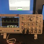
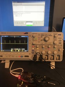
It is now Monday morning in Munich. After flying all night I am here waiting for ride to the show in Nuremberg. Saturday turned out to be a little bit stressful. After getting the Servo Motors working correctly I tried to make the final connection between the WICED WiFI Board and the Secret New Chip board via I2C. But that connection was not working. Why? I didn’t know, but all of my theories were bad e.g. does the new chip have a bug in the I2C (nope). Finally after hours and hours of thinking about it, making logic analyzer traces, trying different boards, etc. I called my friend Greg who said “Oh, if the I2C slave stretches the clock on the 43907 I2C master, it doesn’t work. Don’t you remember that I told you that?”
Fixing the Secret Chip Firmware
The firmware fix was kind of a workaround rather than a permanent fix. I did two things to try make sure that the new chip didnt stretch the clock. (I am not sure that either is a guarantee).
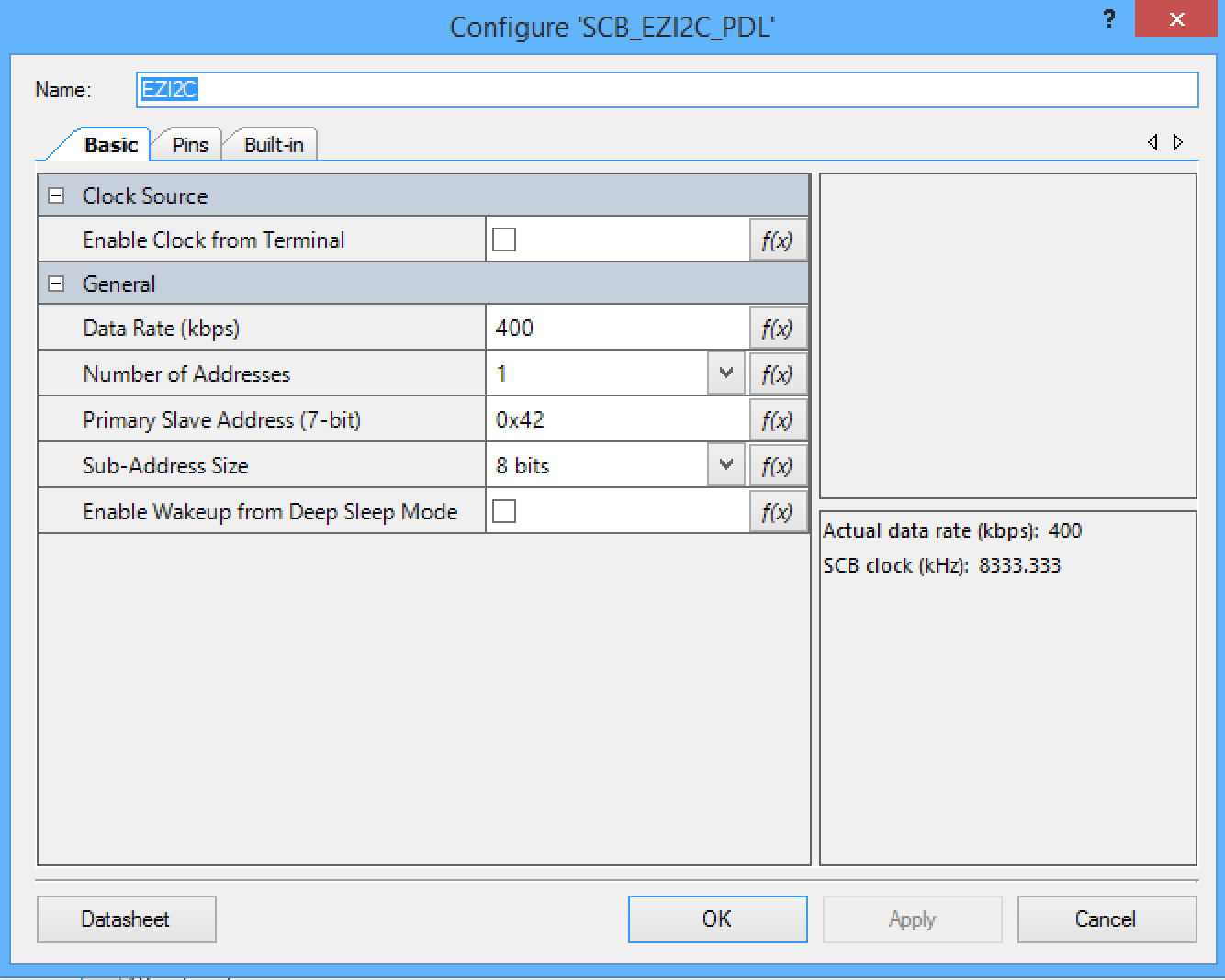
First, I increased the speed of the I2C bus. I doubt that this guarantees that the I2C clock is not stretched, but it seems to work.
Second, I increased the priority of the EZI2C interrupt (though I don’t think that in this case it actually mattered). This picture shows something interesting about the new chip. I called the BU manager and he told me that I could say that it is a multicore chip. 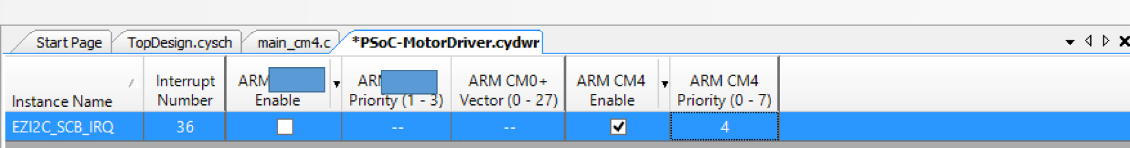
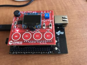
Modifying the Subscriber Application
Now that I have the communication working between the WICED WiFi development kit and the secret new chip development kit, I need to make a change or two to the Subscriber firmware to send updates to the Robot ARM controller. One good thing about spending hours trying to figure out why the I2C was not working is that I greatly improved the Subscriber firmware.
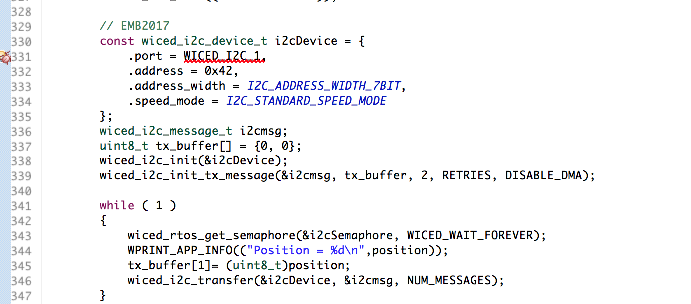
In the modified firmware
- Lines 330-338 setup the I2C bus interface
- Line 337 defines a two byte buffer that will be sent each time a new message is published. The first byte is the address in the I2C slave (in this case 0) and the 2nd byte is the value for the new position (in percent)
- Lines 341-346 are the main loop for the new firmware. It just waits for the semaphore in the MQTT code to be set, then it prints out the position (line 344), then sends it to the slave (line 345-346)
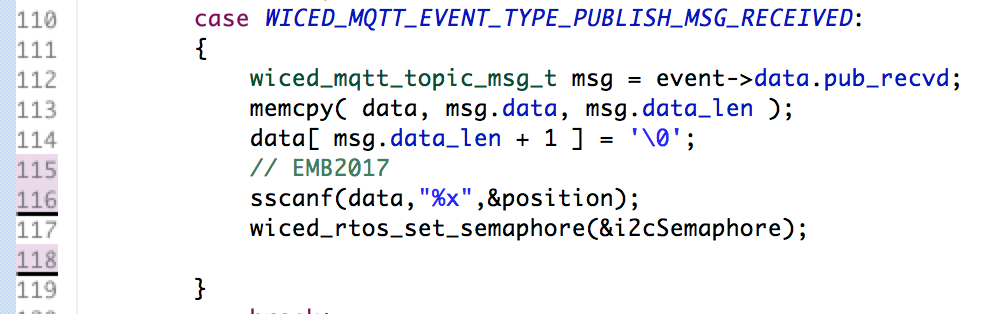
The last things that needs to be changed is to set the semaphore when a new message is received from the MQTT Message Broker:
- When the message is received
- Turn the ASCII hex value into a Integer (line 116)
- Set the semaphore to tell the main loop to send the data (line 117)
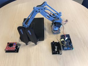
Conclusion
Everything is done and working… and checked into GitHub. You can find it at GitHub.com:iotexpert/emb2017. Come see me talk at Embedded World… as always I am never sure what I will say next, which apparently makes for a good show. Ill leave you with this image of my office, which is a total disaster area.


No comment yet, add your voice below!